EP4102694A1 - Inverter for an electric motor - Google Patents
Inverter for an electric motor Download PDFInfo
- Publication number
- EP4102694A1 EP4102694A1 EP21178428.5A EP21178428A EP4102694A1 EP 4102694 A1 EP4102694 A1 EP 4102694A1 EP 21178428 A EP21178428 A EP 21178428A EP 4102694 A1 EP4102694 A1 EP 4102694A1
- Authority
- EP
- European Patent Office
- Prior art keywords
- inverter
- board
- transistor
- capacitor
- cooling element
- Prior art date
- Legal status (The legal status is an assumption and is not a legal conclusion. Google has not performed a legal analysis and makes no representation as to the accuracy of the status listed.)
- Pending
Links
Images


Classifications
-
- H—ELECTRICITY
- H02—GENERATION; CONVERSION OR DISTRIBUTION OF ELECTRIC POWER
- H02K—DYNAMO-ELECTRIC MACHINES
- H02K9/00—Arrangements for cooling or ventilating
- H02K9/19—Arrangements for cooling or ventilating for machines with closed casing and closed-circuit cooling using a liquid cooling medium, e.g. oil
-
- H—ELECTRICITY
- H02—GENERATION; CONVERSION OR DISTRIBUTION OF ELECTRIC POWER
- H02K—DYNAMO-ELECTRIC MACHINES
- H02K11/00—Structural association of dynamo-electric machines with electric components or with devices for shielding, monitoring or protection
- H02K11/30—Structural association with control circuits or drive circuits
- H02K11/33—Drive circuits, e.g. power electronics
-
- H—ELECTRICITY
- H02—GENERATION; CONVERSION OR DISTRIBUTION OF ELECTRIC POWER
- H02K—DYNAMO-ELECTRIC MACHINES
- H02K11/00—Structural association of dynamo-electric machines with electric components or with devices for shielding, monitoring or protection
- H02K11/0094—Structural association with other electrical or electronic devices
-
- H—ELECTRICITY
- H02—GENERATION; CONVERSION OR DISTRIBUTION OF ELECTRIC POWER
- H02K—DYNAMO-ELECTRIC MACHINES
- H02K11/00—Structural association of dynamo-electric machines with electric components or with devices for shielding, monitoring or protection
- H02K11/02—Structural association of dynamo-electric machines with electric components or with devices for shielding, monitoring or protection for suppression of electromagnetic interference
-
- H—ELECTRICITY
- H02—GENERATION; CONVERSION OR DISTRIBUTION OF ELECTRIC POWER
- H02K—DYNAMO-ELECTRIC MACHINES
- H02K11/00—Structural association of dynamo-electric machines with electric components or with devices for shielding, monitoring or protection
- H02K11/30—Structural association with control circuits or drive circuits
-
- H—ELECTRICITY
- H02—GENERATION; CONVERSION OR DISTRIBUTION OF ELECTRIC POWER
- H02K—DYNAMO-ELECTRIC MACHINES
- H02K5/00—Casings; Enclosures; Supports
- H02K5/04—Casings or enclosures characterised by the shape, form or construction thereof
- H02K5/20—Casings or enclosures characterised by the shape, form or construction thereof with channels or ducts for flow of cooling medium
- H02K5/203—Casings or enclosures characterised by the shape, form or construction thereof with channels or ducts for flow of cooling medium specially adapted for liquids, e.g. cooling jackets
-
- H—ELECTRICITY
- H02—GENERATION; CONVERSION OR DISTRIBUTION OF ELECTRIC POWER
- H02M—APPARATUS FOR CONVERSION BETWEEN AC AND AC, BETWEEN AC AND DC, OR BETWEEN DC AND DC, AND FOR USE WITH MAINS OR SIMILAR POWER SUPPLY SYSTEMS; CONVERSION OF DC OR AC INPUT POWER INTO SURGE OUTPUT POWER; CONTROL OR REGULATION THEREOF
- H02M1/00—Details of apparatus for conversion
- H02M1/44—Circuits or arrangements for compensating for electromagnetic interference in converters or inverters
-
- H—ELECTRICITY
- H02—GENERATION; CONVERSION OR DISTRIBUTION OF ELECTRIC POWER
- H02M—APPARATUS FOR CONVERSION BETWEEN AC AND AC, BETWEEN AC AND DC, OR BETWEEN DC AND DC, AND FOR USE WITH MAINS OR SIMILAR POWER SUPPLY SYSTEMS; CONVERSION OF DC OR AC INPUT POWER INTO SURGE OUTPUT POWER; CONTROL OR REGULATION THEREOF
- H02M7/00—Conversion of ac power input into dc power output; Conversion of dc power input into ac power output
- H02M7/42—Conversion of dc power input into ac power output without possibility of reversal
- H02M7/44—Conversion of dc power input into ac power output without possibility of reversal by static converters
- H02M7/48—Conversion of dc power input into ac power output without possibility of reversal by static converters using discharge tubes with control electrode or semiconductor devices with control electrode
- H02M7/53—Conversion of dc power input into ac power output without possibility of reversal by static converters using discharge tubes with control electrode or semiconductor devices with control electrode using devices of a triode or transistor type requiring continuous application of a control signal
- H02M7/537—Conversion of dc power input into ac power output without possibility of reversal by static converters using discharge tubes with control electrode or semiconductor devices with control electrode using devices of a triode or transistor type requiring continuous application of a control signal using semiconductor devices only, e.g. single switched pulse inverters
-
- H—ELECTRICITY
- H02—GENERATION; CONVERSION OR DISTRIBUTION OF ELECTRIC POWER
- H02P—CONTROL OR REGULATION OF ELECTRIC MOTORS, ELECTRIC GENERATORS OR DYNAMO-ELECTRIC CONVERTERS; CONTROLLING TRANSFORMERS, REACTORS OR CHOKE COILS
- H02P27/00—Arrangements or methods for the control of AC motors characterised by the kind of supply voltage
- H02P27/04—Arrangements or methods for the control of AC motors characterised by the kind of supply voltage using variable-frequency supply voltage, e.g. inverter or converter supply voltage
- H02P27/06—Arrangements or methods for the control of AC motors characterised by the kind of supply voltage using variable-frequency supply voltage, e.g. inverter or converter supply voltage using dc to ac converters or inverters
-
- H—ELECTRICITY
- H05—ELECTRIC TECHNIQUES NOT OTHERWISE PROVIDED FOR
- H05K—PRINTED CIRCUITS; CASINGS OR CONSTRUCTIONAL DETAILS OF ELECTRIC APPARATUS; MANUFACTURE OF ASSEMBLAGES OF ELECTRICAL COMPONENTS
- H05K7/00—Constructional details common to different types of electric apparatus
- H05K7/20—Modifications to facilitate cooling, ventilating, or heating
- H05K7/2089—Modifications to facilitate cooling, ventilating, or heating for power electronics, e.g. for inverters for controlling motor
- H05K7/20927—Liquid coolant without phase change
-
- H—ELECTRICITY
- H02—GENERATION; CONVERSION OR DISTRIBUTION OF ELECTRIC POWER
- H02K—DYNAMO-ELECTRIC MACHINES
- H02K2203/00—Specific aspects not provided for in the other groups of this subclass relating to the windings
- H02K2203/03—Machines characterised by the wiring boards, i.e. printed circuit boards or similar structures for connecting the winding terminations
-
- H—ELECTRICITY
- H02—GENERATION; CONVERSION OR DISTRIBUTION OF ELECTRIC POWER
- H02K—DYNAMO-ELECTRIC MACHINES
- H02K5/00—Casings; Enclosures; Supports
- H02K5/04—Casings or enclosures characterised by the shape, form or construction thereof
- H02K5/22—Auxiliary parts of casings not covered by groups H02K5/06-H02K5/20, e.g. shaped to form connection boxes or terminal boxes
- H02K5/225—Terminal boxes or connection arrangements
-
- H—ELECTRICITY
- H02—GENERATION; CONVERSION OR DISTRIBUTION OF ELECTRIC POWER
- H02M—APPARATUS FOR CONVERSION BETWEEN AC AND AC, BETWEEN AC AND DC, OR BETWEEN DC AND DC, AND FOR USE WITH MAINS OR SIMILAR POWER SUPPLY SYSTEMS; CONVERSION OF DC OR AC INPUT POWER INTO SURGE OUTPUT POWER; CONTROL OR REGULATION THEREOF
- H02M7/00—Conversion of ac power input into dc power output; Conversion of dc power input into ac power output
- H02M7/003—Constructional details, e.g. physical layout, assembly, wiring or busbar connections
Definitions
- the invention relates to an inverter for electric motor.
- the invention also relates to an electric motor comprising such an inverter.
- An electric motor usually comprises a rotor and a stator, which cooperate electromagnetically with one another.
- An inverter usually comprises a capacitor board comprising capacitors, a transistor board, and a control board, and converts the direct current into the phase current for the stator.
- the heat generated during the conversion of the direct current into the phase current has to be discharged to the outside thereof.
- compromises have to be made from time to time due to a small available installation space in the inverter. This can result in that the components of the inverter are not cooled sufficiently and/or the assembly of the inverter is made more difficult.
- An inverter for an electric motor.
- the inverter thereby comprises a capacitor board comprising at least one capacitor, at least one transistor board, and a cooling element.
- the capacitor board and the at least one transistor board are each aligned transversely to a longitudinal central axis of the inverter and are electrically interconnected.
- the cooling element is pot-shaped and forms a housing, which receives the capacitor board and the at least one transistor board.
- the capacitor board and the at least one transistor board are received in the housing or the cooling element, respectively.
- the capacitor board and the at least one transistor board, as well as optionally further components of the inverter are thereby supported by the housing or the cooling element, respectively.
- the capacitor board and the at least one transistor board, as well as optionally further components of the inverter can thus be arranged in a space-saving manner in the housing or the cooling element, respectively, and can be cooled effectively by means of the housing or the cooling element, respectively.
- Further components of the inverter can be, for example, a control board, which is then received in the same way in the housing or in the cooling element, respectively.
- the inverter according to the invention thereby has the longitudinal central axis and, with respect to its longitudinal central axis, a longitudinal end facing the motor, and a longitudinal end facing away from the motor.
- the two longitudinal ends are thereby arranged so as to be located opposite one another with respect to the longitudinal central axis.
- the pot-shaped cooling element is open towards the longitudinal end of the inverter, which faces the motor.
- the cooling element can be cast from aluminum.
- the inverter can have six transistor boards and can be provided for a six-phase motor.
- the capacitor board can have several capacitors.
- the respective capacitor can be material bonded, preferably welded, to the capacitor board at four negative pole contact points and at a positive pole contact point, and can thus be contacted in an electrically conductive manner.
- the cooling element has at least one cooling duct, through which a cooling liquid can flow.
- the cooling element has a bottom, which is aligned transversely to the longitudinal central axis, and a wall, which extends from the perimeter of the bottom and parallel to the longitudinal central axis.
- a passage opening for contact lines of the inverter can be formed centrally in the bottom. The bottom of the cooling element can thereby be arranged with the passage opening at the end of the inverter facing away from the motor.
- the cooling element has at least one cooling duct, through which a cooling liquid can flow.
- the at least one cooling duct can thereby be formed in the bottom of the cooling element so as to surround the passage opening.
- the capacitor board and the at least one transistor board, as well as optionally further components of the inverter, can thus be cooled effectively and actively.
- the cooling element has a pot element produced by means of die casting, and a cover plate aligned transversely to the longitudinal central axis.
- at least one cooling duct which is open on one side and which is aligned transversely to the longitudinal central axis, is formed in the pot element on the outer side.
- the cover plate then axially and sealingly closes the at least one cooling duct, which is formed in the pot element and is open on one side, and the cover plate is material bonded, preferably soldered, or firmly attached, preferably via a gasket, to the pot element.
- the cooling element can have an inlet nozzle and/or an outlet nozzle.
- the inlet nozzle and/or the outlet nozzle can be material bonded, preferably soldered, to the pot element.
- the inlet nozzle and/or the outlet nozzle can be fluidically connected to the at least one cooling duct.
- the inverter contains a single transistor board, which is annular and is arranged so as to surround the longitudinal central axis.
- the inverter contains at least two transistor boards, which are arranged so as to surround and so as to be distributed evenly around the longitudinal central axis of the inverter.
- the transistor board can thereby be pressed against the cooling element from the inside so as to transfer heat and can thus be cooled particularly effectively.
- the capacitor board can contain at least two capacitors and the capacitors can be arranged so as to surround at least in some regions and so as to be distributed at least in some regions evenly around the longitudinal central axis.
- the transistor boards can be arranged so as to surround and so as to be distributed at least in some regions evenly around the longitudinal central axis and around the capacitors.
- the cooling element can surround the at least one capacitor of the capacitor board on several sides, so that the at least one capacitor is stabilized against vibration and is cooled.
- the at least one transistor board and the capacitor board can be material bonded to one another, preferably welded, and can thus be contacted in an electrically conductive manner.
- the respective transistor board and the capacitor board can be connected to one another on one side so as to allow relative movement between the respective transistor board and the capacitor board. This can be critical during assembling and beneficial for compensating of a thermal expansion and contraction during operation of the inverter.
- the inverter in each case has a spring element and an electrically conductive contact plate for each of the at least one transistor board.
- the respective spring element can thereby be arranged axially between the respective contact plate and the respective transistor board, and can resiliently connect the respective transistor board and the respective contact plate to one another.
- the respective transistor board can then be pressed via the respective spring element against the cooling element so as to transfer heat.
- the respective transistor board can be arranged axially adjacent to the cooling element.
- the respective contact plate and the respective spring element can be arranged at the respective transistor board so as to face axially away from the cooling element.
- the respective transistor board and the respective contact plate can be material bonded to one another, preferably welded, and can thus be contacted in an electrically conductive manner.
- the respective transistor board and the respective contact plate can be connected to one another on one side.
- the respective transistor board and the respective contact plate can be connected to one another so as to allow relative movement between the transistor board and the respective contact plate.
- the respective spring element can be material bonded, preferably welded, to the respective contact plate.
- the respective spring element can advantageously be formed of steel.
- the inverter has an electrically insulating spacer.
- the spacer thereby receives the at least one capacitor of the capacitor board at least in some regions, and positions the at least one capacitor in the cooling element spaced apart from the cooling element and in an electrically insulating manner.
- a heat-conducting curing casting compound can be arranged between the cooling element and the at least one capacitor of the capacitor board.
- the casting compound can cure only when the capacitor board is arranged in the cooling element with the at least one capacitor and the spacer. The at least one capacitor of the capacitor board can thus be stabilized against vibration and can be cooled.
- the at least one capacitor of the capacitor board can be received in the cooling element so as to face the longitudinal end of the inverter, which faces away from the motor.
- a receiving recess can be formed in the cooling element for the at least one capacitor of the capacitor board and for the spacer.
- the at least one capacitor of the capacitor board can then be received in the receiving recess of the cooling element.
- the at least one capacitor can thereby be surrounded by the cooling element transversely to the longitudinal central axis and laterally around the longitudinal central axis.
- the at least one capacitor of the capacitor board can thus be cooled effectively, inter alia by external air by means of a heat exchange via the cooling element and the heat-conducting casting compound.
- the capacitor board can contain several capacitors. In this case, the capacitors can surround or encircle the longitudinal central axis.
- the inverter has an electrically insulating carrier, preferably made of plastic.
- the capacitor board can then be arranged on the carrier together with the at least one transistor board, which is firmly connected to the capacitor board, and the capacitor board can be firmly connected, preferably screwed, to the carrier.
- the inverter can have further components, which are firmly connected, preferably screwed, to the carrier.
- the inverter can have a control board, which is firmly connected, preferably screwed, to the carrier. Signal contacts for controlling the control board can thereby be material bonded, preferably soldered, to the control board, and can thus be contacted in an electrically conductive manner.
- the inverter contains at least one positioning unit for the at least one transistor board.
- the at least one positioning unit can contain at least one positioning projection and at least one positioning opening, which axially engage in each other.
- the positioning projection is thereby formed on the carrier and the positioning opening is formed in the at least one transistor board and/or in at least one contact plate which is arranged on the at least one transistor board and/or in at least one spring element which is arranged on the at least one transistor board.
- the inverter has an EMI filter (EMI: ElectroMagnetic Interference). At a longitudinal end of the inverter, which faces away from the motor, the EMI filter can thereby be fastened to the cooling element externally and so as to transfer heat.
- EMI filter ElectroMagnetic Interference
- the EMI filter can thereby be electrically contacted between the capacitor board of the inverter and direct current battery terminals of the inverter.
- the EMI filter can be contacted with the capacitor board in an electrically conductive manner.
- the EMI filter can be material bonded, preferably welded, to the capacitor board, and can thus be contacted in an electrically conductive manner.
- the EMI filter can have three positive pole contacts and three negative pole contacts, which are material bonded, preferably welded, to corresponding copper plates of the capacitor board, and which are thus contacted in an electrically conductive manner.
- the EMI filter can be material bonded, preferably welded, to the capacitor board from longitudinal end of the inverter, which faces the motor, and can thus be electrically contacted.
- the invention also relates to an electric motor comprising an inverter.
- the inverter is thereby axially attached to the motor with a longitudinal end, which faces the motor.
- the motor is contacted with the inverter in an electrically conductive manner via at least one phase terminal, which extends axially to the inverter.
- the inverter is formed as described above.
- the inverter With reference to its longitudinal central axis, the inverter thereby has the above-mentioned longitudinal end, which faces the motor, and a longitudinal end, which faces away from the motor.
- the pot-shaped cooling element is thereby open at the longitudinal end of the inverter, which faces the motor.
- the pot-shaped cooling element externally surrounds the capacitor board and the at least one transistor board, as well as optionally further components of the inverter, on all sides towards the motor.
- the capacitor board and the at least one transistor board, as well as optionally further components of the inverter can thus be protected externally and can be cooled efficiently.
- the inverter and the motor can be firmly connected to one another, preferably screwed.
- the phase terminal can be formed in the form of a cylindrical connecting piece at least in some regions.
- the respective phase terminal of the motor can be electrically conductive.
- the respective phase terminal of the motor can be contacted in an electrically conductive manner with the respective contact plate of the inverter.
- the respective phase terminal of the motor can generate an axial pressing force on the respective contact plate.
- the respective contact plate can then press the respective transistor board via the respective spring element against the cooling element in an axial manner and so as to transfer heat by means of the axial pressing force of the phase terminal.
- at least one cooling duct can be formed in the cooling element.
- At least one motor cooling duct can be formed in the motor.
- the cooling duct in the cooling element of the inverter can directly engage with the motor cooling duct in the motor.
- the cooling element can have an inlet nozzle and an outlet nozzle which are fluidly connected with the at least one cooling duct in the cooling element.
- the motor can have a motor inlet nozzle and a motor outlet nozzle which are fluidly connected with the at least one motor cooling duct in the motor.
- the cooling element can have a pot element and a cover plate aligned transversely to the longitudinal central axis.
- the inlet or outlet nozzle can be integrally formed with the pot element and can directly engage with the motor inlet or outlet nozzle in the motor. Directly engaging means that when the inverter and the motor are rigidly connected to one another, the cooling duct in the cooling element is in communication with the motor cooling duct in the motor, without the need to connect additional tubing.
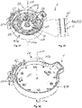
- Fig. 1 shows an exploded view of an inverter 1 according to the invention.
- the inverter 1 thereby has a longitudinal central axis LA. With respect to the longitudinal central axis LA, a longitudinal end 2a facing away from the motor and a longitudinal end 2b facing the motor are specified in the inverter 1.
- the inverter 1 thereby has an EMI filter 3, a cooling element 4, a spacer 5, a capacitor board 6, six transistor boards 7, six contacting units 8, a carrier 9, and a control board 10.
- the EMI filter 3 is electrically connected between the capacitor board 6 and direct current battery terminals 39 of the inverter.
- the EMI filter 3 thereby has an electric filter circuit of several capacitors, not shown here, and a choke 11.
- the capacitors and the choke 11 of the EMI filter are received in an EMI housing 38 of the EMI filter 3.
- the EMI filter 3 is material bonded, preferably welded, to the capacitor board 6 via the throttle 11, and is thus contacted in an electrically conductive manner.
- the EMI filter 3 is screwed to the cooling element 3 by means of a screw group 3a comprising several screws.
- the cooling element 4 is pot-shaped and forms a housing 12 of the inverter.
- the cooling element 4 thereby receives the other components of the inverter 1 and surrounds them externally.
- the cooling element 4 thereby has a pot-shaped pot element 13, a cover plate 14, a separate inlet nozzle 15a, and an outlet nozzle 15b, which is integrated in the pot element 13.
- the pot element 13 is thereby produced of aluminum by means of a die casting process, and the cover plate 14 as well as the inlet nozzle 15a are material bonded, preferably soldered, to the pot element.
- the cooling element 4 thereby has a bottom 16 and a wall 17.
- the bottom 16 is thereby aligned transversely to the longitudinal central axis LA, and the wall 17 is aligned parallel to the longitudinal central axis LA, and surrounds the longitudinal central axis LA.
- the cooling element 4 has a cooling duct 18, through which a cooling liquid can flow, and a passage opening 19 for the EMI filter 3.
- the passage opening 19 is thereby formed centrally in the bottom 16, and the cooling duct 18 is formed in the bottom 16 so as to surround the passage opening 19.
- the cooling duct 18 is thereby formed to be open on one side in the pot element 13 and is fluidically closed externally by means of the cover plate 14.
- the capacitor board 6 has several capacitors 20, which are arranged symmetrically around the longitudinal central axis LA on the capacitor board 6.
- the capacitors 20 are thereby material bonded, preferably welded, to the capacitor board 6, and are thus contacted in an electrically conductive manner.
- the transistor boards 7 are arranged so as to surround the longitudinal central axis LA and so as to be distributed evenly around the capacitors 20 of the capacitor board 6.
- the transistor boards 7 are thereby material bonded, preferably welded, to the capacitor board 6 at contact points 21, and are thus contacted in an electrically conductive manner.
- the spacer 5 is electrically insulating and is arranged axially between the capacitor board 6 and the bottom 16 of the cooling element 4. The spacer 5 thereby receives the capacitors 20 of the capacitor board 6 and insulates them electrically from the cooling element 4.
- a curing heat-transferring casting compound can be arranged between the capacitors 20 and the cooling element 4.
- the contacting units 8 each have an electrically conductive contact plate 22 and a spring element 23.
- the respective contact plate 22 is thereby material bonded, preferably welded, to the respective transistor board 7, and is thus contacted in an electrically conductive manner.
- the contact plate 22 is material bonded, preferably welded, to the respective spring element 23.
- the contact plates 22 are provided for contacting with phase terminals of the motor, as will be described in more detail below on the basis of Fig. 24 and Fig. 25 .
- the carrier 9 is formed of plastic and carries the capacitor board 6 comprising the transistor boards 7.
- the contacting units 8 are thereby arranged between the carrier 9 and the transistor boards 7.
- the contact plates 22 are thereby arranged so as to face the carrier 9.
- the capacitor board 6 is screwed to the carrier 9 by means of a screw group comprising several screws, not shown here.
- contact elements 24 are received in the carrier 9.
- the control board 10 is screwed to the carrier 9 by means of a screw group 10a comprising several screws.
- a screw group 10a comprising several screws.
- six ring-shaped cores 25 are arranged between the control board 10 and the carrier 9. If the inverter 1 is contacted with the motor, as will be described in more detail below on the basis of Fig. 24 and Fig. 25 , the respective cores 25 are located around the respective phase terminals of the motor.
- Fig. 2 shows a view of the inverter 1 according to the invention.
- the inverter 1 is shown in the assembled state from the longitudinal end 2a, which faces away from the motor.
- Fig. 3 shows a sectional view
- Fig. 4 shows a view of one of the transistor boards 7 comprising the contacting unit 8.
- the respective contact plate 22 of the contacting unit 8 is thereby material bonded, preferably welded, to the respective transistor board 7 at a first point 26a, and is thus contacted in an electrically conductive manner.
- the contact plate 22 is material bonded, preferably welded, to the respective spring element 23 at a second point 26b.
- the spring element 23 is thereby resiliently arranged between the contact plate 22 and the transistor board 7.
- a contact opening 27 for inserting and for contacting the respective phase terminal of the motor, is thereby formed centrally in the contact plate 22, as will be described in more detail below on the basis of Fig. 24 and Fig. 25 .
- six contact pins 28, which are aligned to the inside into the contact opening 27 and from the spring element 23 axially to the outside, are formed at the contact opening 27.
- signal pins 29 can be seen at the respective transistor board 7.
- Fig. 5 shows a view of the capacitor board 6 from the longitudinal end 2b, which faces the motor.
- Fig. 6 shows a view of the capacitor board 6 from the longitudinal end 2a, which faces away from the motor.
- the capacitor board 6 thereby has an electrically conductive negative pole plate 30a and an electrically conductive positive pole plate 30b.
- a dielectric intermediate plate 30c is arranged between the negative pole plate 30a and the positive pole plate 30b.
- the negative pole plate 30a is arranged so as to face the longitudinal end 2a, which faces away from the motor
- the positive pole plate 30b is arranged so as to face the longitudinal end 2b, which faces the motor.
- the respective capacitor 20 is thereby connected to the negative pole plate 30a at four negative pole contact points 31a and to the positive pole plate 30b at a positive pole contact point 21b, and material bonded, preferably welded, and is thus contacted in an electrically conductive manner.
- six contact points 32 can be seen in the center, which are provided for contacting the capacitor board 6 with the power supply bus bars of the EMI filter 3.
- Fig. 7 shows a sectional view
- Fig. 8 shows an enlarged sectional view of the capacitor board 6.
- Two of the four negative pole contact points 31a and the positive pole contact point 31b can be seen particularly well in Fig. 7 and in Fig. 8 .
- Fig. 9 shows a view of the capacitor board 6 comprising the transistor boards 7 from the longitudinal end 2a, which faces away from the motor.
- Fig. 10 shows a view of the capacitor board 6 comprising the transistor boards 7 from the longitudinal end 2b, which faces the motor.
- the respective transistor boards 7 are thereby material bonded, preferably welded, to the capacitor board 6 at three respective contact points 21, and are thus contacted in an electrically conductive manner.
- the respective transistor board 7 is thereby contacted in an electrically conductive manner with two contact points 21 with the positive pole plate 30b and with one contact point 21 with the negative pole plate 30a.
- Fig. 11 shows a view of the carrier 9 from the longitudinal end 2b, which faces the motor.
- Fig. 12 shows a view of the carrier 9 from the longitudinal end 2a, which faces away from the motor.
- the ring-shaped cores 25 are already arranged at the carrier 9 in Fig. 11 .
- the carrier 9 is thereby dielectric or electrically non-conductive and is formed of plastic.
- Fig. 13 shows a view of the carrier 9 comprising the capacitor board 6 and comprising the transistor boards 7, which are arranged on a side of the carrier 9 facing the longitudinal end 2a, which faces away from the motor.
- the arrangement shown in Fig. 9-10 is thus arranged in the carrier 9.
- the capacitor board 6 is thereby screwed to the carrier 9 by means of a screw group 6a comprising several screws.
- Fig. 14 shows a view of the cooling element 4 from the longitudinal end 2a, which faces away from the motor.
- Fig. 15 shows an exploded view of the cooling element 4 from the longitudinal end 2a, which faces away from the motor.
- a solder ring 33 can be seen here, by means of which the inlet nozzle 15a is soldered to the pot element 13 and/or the cover plate 14.
- Fig. 16 shows a view of the spacer 5 from the longitudinal end 2b, which faces the motor.
- the spacer 5 is dielectric or electrically non-conductive, respectively.
- Fig. 17 shows a view of the cooling element 4 comprising the spacer 5 from the longitudinal end 2b, which faces the motor.
- the spacer 5 is thereby arranged in a receiving recess 34 of the cooling element 4.
- Fig. 18 shows a view of the cooling element 4 comprising the spacer 5 and comprising the arrangement from Fig. 9-10 from the longitudinal end 2b, which faces the motor.
- the capacitors 20 are already received in the spacer 5.
- the capacitors 20 are thereby received in the receiving recess 34 and are surrounded by the cooling element 4 transversely to the central longitudinal axis LA and so as to surround the longitudinal central axis LA.
- the capacitors 20 can thus be cooled effectively.
- a heat-conductive curable casting compound is arranged between the cooling element 4 and the capacitors 20, and can support the heat exchange between the capacitors 20 and the cooling element 4.
- Fig. 19 shows a view of the EMI filter 3 from the longitudinal end 2a, which faces away from the motor. In particular some of three flat negative pole contacts 35a and three flat positive pole contacts 35b of the choke 11 can be seen here.
- the EMI filter 3 has several capacitors, which are switched to form a filter circuit. The filter circuit is thereby arranged in the electrically insulating EMI housing 38.
- Fig. 20 shows a view of the arrangement from Fig. 18 comprising the EMI filter 3 from the longitudinal end 2a, which faces away from the motor.
- Fig. 21 shows a view of the arrangement from Fig. 18 comprising the EMI filter 3 from the longitudinal end 2b, which faces away from the motor.
- the EMI filter 3 is thereby material bonded, preferably welded, to the capacitor board 6 at contact points 32, and is thus contacted in an electrically conductive manner.
- the negative pole contacts 35a of the choke 11 are thereby electrically contacted with the negative pole plate 30a of the capacitor board 6, and the positive pole contacts 35b of the choke 11 are electrically contacted with the positive pole plate 30b of the capacitor board 6.
- FIG. 22 An enlarged view of the contact points 32 of the capacitor board 6 is shown in Fig. 22 .
- the respective contact point 32 is thereby formed by two longer seams on both sides of the negative pole contact 35a or at the positive pole contact 35b of the power supply bus bars, respectively.
- Fig. 23 shows a view of the arrangement from Fig. 18 comprising the control board 10 from the longitudinal end 2b, which faces the motor.
- the control board 10 is thereby screwed to the carrier 9 by means of the screw group 10a comprising several screws.
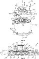
- Fig. 24 shows an exploded view of a motor 36 according to the invention comprising the inverter 1 according to the invention.
- the inverter 1 is thereby axially attached to the motor 36 with the longitudinal end 2b, which faces the motor.
- the motor 36 is electrically contacted with the inverter 1 via six phase terminals 37.
- the phase terminals 37 are thereby formed at least in some regions in the form of a cylindrical connecting piece, which extends axially towards the inverter 1.
- the inverter 1 and the motor 36 are screwed to one another by means of a screw group 1a comprising several screws.
- Fig. 25 shows a sectional view of the motor 36 comprising the inverter 1.
- the respective phase terminal 37 protrudes axially into the inverter 1 and is electrically contacted with the respective contact plate 22.
- the respective phase terminal 37 is thereby received in the contact opening 27 of the contact plate 22 and is thus connected to the contact plate 22 in an electrically conductive manner.
- the phase terminal 37 is thereby formed in such a way that an axial pressing force acts on the contact plate 22.
- the respective contact plate 22 therefore presses the respective transistor board 7 via the respective spring element 23 against the cooling element 4 so as to transfer heat.
- the inverter 1 contains six positioning units 40 for each of the transistor boards 7.
- the respective positioning unit 40 contains two positioning projections 40a and six positioning openings 41b.
- the positioning projections 41a are formed on the carrier 9 and projects axially to the respective transistor board 7. Two of the positioning openings 41b are formed in the respective transistor board 7, two of the position openings 41 b are formed in the respective contact plate 22, and two of the position openings 41b are formed in the respective spring element 23.
- the respective positioning projection 41a axially engages with the respective position opening 41b in the respective transistor board 7, with the respective position opening 41b in the respective contact plate 22, and with the respective position opening 41b in the respective spring element 23.
- the positioning unit 40 allows an axially compression of the assembly and prevents a side to side movement between the respective transistor plate 7, the respective contact plate 22, the respective spring element 23 and the carrier 9.
- the design of the inverter 1 can be adapted to different diameters of the motor 36.
Abstract
Description
- The invention relates to an inverter for electric motor. The invention also relates to an electric motor comprising such an inverter.
- An electric motor usually comprises a rotor and a stator, which cooperate electromagnetically with one another. An inverter usually comprises a capacitor board comprising capacitors, a transistor board, and a control board, and converts the direct current into the phase current for the stator. The heat generated during the conversion of the direct current into the phase current has to be discharged to the outside thereof. However, compromises have to be made from time to time due to a small available installation space in the inverter. This can result in that the components of the inverter are not cooled sufficiently and/or the assembly of the inverter is made more difficult.
- It is thus the object of the invention to provide an improved or at least alternative embodiment for an inverter of the generic type, which overcomes the described disadvantages. It is also the object of the invention to provide an electric motor comprising the inverter.
- According to the invention, these objects are solved by means of the subject matter of the independent claims. Advantageous embodiments are subject matter of the dependent claims.
- An inverter is provided for an electric motor. The inverter thereby comprises a capacitor board comprising at least one capacitor, at least one transistor board, and a cooling element. The capacitor board and the at least one transistor board are each aligned transversely to a longitudinal central axis of the inverter and are electrically interconnected. According to the invention, the cooling element is pot-shaped and forms a housing, which receives the capacitor board and the at least one transistor board.
- In the inverter according to the invention, the capacitor board and the at least one transistor board are received in the housing or the cooling element, respectively. The capacitor board and the at least one transistor board, as well as optionally further components of the inverter, are thereby supported by the housing or the cooling element, respectively. The capacitor board and the at least one transistor board, as well as optionally further components of the inverter, can thus be arranged in a space-saving manner in the housing or the cooling element, respectively, and can be cooled effectively by means of the housing or the cooling element, respectively. Further components of the inverter can be, for example, a control board, which is then received in the same way in the housing or in the cooling element, respectively.
- The inverter according to the invention thereby has the longitudinal central axis and, with respect to its longitudinal central axis, a longitudinal end facing the motor, and a longitudinal end facing away from the motor. The two longitudinal ends are thereby arranged so as to be located opposite one another with respect to the longitudinal central axis. According to the intended purpose, the pot-shaped cooling element is open towards the longitudinal end of the inverter, which faces the motor. The terms "axially" and "radially" thereby always refer to the longitudinal central axis of the inverter.
- Advantageously, the cooling element can be cast from aluminum. Advantageously, the inverter can have six transistor boards and can be provided for a six-phase motor. Advantageously, the capacitor board can have several capacitors. Advantageously, the respective capacitor can be material bonded, preferably welded, to the capacitor board at four negative pole contact points and at a positive pole contact point, and can thus be contacted in an electrically conductive manner. Advantageously, it can be provided that the cooling element has at least one cooling duct, through which a cooling liquid can flow.
- Advantageously, it can be provided that the cooling element has a bottom, which is aligned transversely to the longitudinal central axis, and a wall, which extends from the perimeter of the bottom and parallel to the longitudinal central axis. In addition, a passage opening for contact lines of the inverter can be formed centrally in the bottom. The bottom of the cooling element can thereby be arranged with the passage opening at the end of the inverter facing away from the motor.
- Advantageously, it can be provided that the cooling element has at least one cooling duct, through which a cooling liquid can flow. The at least one cooling duct can thereby be formed in the bottom of the cooling element so as to surround the passage opening. The capacitor board and the at least one transistor board, as well as optionally further components of the inverter, can thus be cooled effectively and actively.
- Advantageously, it can be provided that the cooling element has a pot element produced by means of die casting, and a cover plate aligned transversely to the longitudinal central axis. In addition, at least one cooling duct, which is open on one side and which is aligned transversely to the longitudinal central axis, is formed in the pot element on the outer side. The cover plate then axially and sealingly closes the at least one cooling duct, which is formed in the pot element and is open on one side, and the cover plate is material bonded, preferably soldered, or firmly attached, preferably via a gasket, to the pot element. Advantageously, the cooling element can have an inlet nozzle and/or an outlet nozzle. The inlet nozzle and/or the outlet nozzle can be material bonded, preferably soldered, to the pot element. Advantageously, the inlet nozzle and/or the outlet nozzle can be fluidically connected to the at least one cooling duct.
- Advantageously, it can be provided that the inverter contains a single transistor board, which is annular and is arranged so as to surround the longitudinal central axis. Advantageously, it can be provided that the inverter contains at least two transistor boards, which are arranged so as to surround and so as to be distributed evenly around the longitudinal central axis of the inverter. The transistor board can thereby be pressed against the cooling element from the inside so as to transfer heat and can thus be cooled particularly effectively. Advantageously, the capacitor board can contain at least two capacitors and the capacitors can be arranged so as to surround at least in some regions and so as to be distributed at least in some regions evenly around the longitudinal central axis. Advantageously, the transistor boards can be arranged so as to surround and so as to be distributed at least in some regions evenly around the longitudinal central axis and around the capacitors.
- Advantageously, the cooling element can surround the at least one capacitor of the capacitor board on several sides, so that the at least one capacitor is stabilized against vibration and is cooled. Advantageously, the at least one transistor board and the capacitor board can be material bonded to one another, preferably welded, and can thus be contacted in an electrically conductive manner. Advantageously, the respective transistor board and the capacitor board can be connected to one another on one side so as to allow relative movement between the respective transistor board and the capacitor board. This can be critical during assembling and beneficial for compensating of a thermal expansion and contraction during operation of the inverter.
- Advantageously, it can be provided that the inverter in each case has a spring element and an electrically conductive contact plate for each of the at least one transistor board. The respective spring element can thereby be arranged axially between the respective contact plate and the respective transistor board, and can resiliently connect the respective transistor board and the respective contact plate to one another. In response to the axial pressing force on the respective contact plate, the respective transistor board can then be pressed via the respective spring element against the cooling element so as to transfer heat. Advantageously, the respective transistor board can be arranged axially adjacent to the cooling element. Advantageously, the respective contact plate and the respective spring element can be arranged at the respective transistor board so as to face axially away from the cooling element.
- Advantageously, the respective transistor board and the respective contact plate can be material bonded to one another, preferably welded, and can thus be contacted in an electrically conductive manner. Advantageously, the respective transistor board and the respective contact plate can be connected to one another on one side. Advantageously, the respective transistor board and the respective contact plate can be connected to one another so as to allow relative movement between the transistor board and the respective contact plate. Advantageously, the respective spring element can be material bonded, preferably welded, to the respective contact plate. However, a different securing of the respective contact plate, of the respective spring element, and of the respective transistor board to one another is generally also conceivable. The respective spring element can advantageously be formed of steel.
- Advantageously, it can be provided that the inverter has an electrically insulating spacer. The spacer thereby receives the at least one capacitor of the capacitor board at least in some regions, and positions the at least one capacitor in the cooling element spaced apart from the cooling element and in an electrically insulating manner. In addition, a heat-conducting curing casting compound can be arranged between the cooling element and the at least one capacitor of the capacitor board. Advantageously, the casting compound can cure only when the capacitor board is arranged in the cooling element with the at least one capacitor and the spacer. The at least one capacitor of the capacitor board can thus be stabilized against vibration and can be cooled.
- Advantageously, the at least one capacitor of the capacitor board can be received in the cooling element so as to face the longitudinal end of the inverter, which faces away from the motor. Advantageously, a receiving recess can be formed in the cooling element for the at least one capacitor of the capacitor board and for the spacer. The at least one capacitor of the capacitor board can then be received in the receiving recess of the cooling element. The at least one capacitor can thereby be surrounded by the cooling element transversely to the longitudinal central axis and laterally around the longitudinal central axis. The at least one capacitor of the capacitor board can thus be cooled effectively, inter alia by external air by means of a heat exchange via the cooling element and the heat-conducting casting compound. Advantageously, the capacitor board can contain several capacitors. In this case, the capacitors can surround or encircle the longitudinal central axis.
- Advantageously, it can be provided that the inverter has an electrically insulating carrier, preferably made of plastic. The capacitor board can then be arranged on the carrier together with the at least one transistor board, which is firmly connected to the capacitor board, and the capacitor board can be firmly connected, preferably screwed, to the carrier. Advantageously, the inverter can have further components, which are firmly connected, preferably screwed, to the carrier. For instance, the inverter can have a control board, which is firmly connected, preferably screwed, to the carrier. Signal contacts for controlling the control board can thereby be material bonded, preferably soldered, to the control board, and can thus be contacted in an electrically conductive manner.
- Advantageously, it can be provided that the inverter contains at least one positioning unit for the at least one transistor board. The at least one positioning unit can contain at least one positioning projection and at least one positioning opening, which axially engage in each other. The positioning projection is thereby formed on the carrier and the positioning opening is formed in the at least one transistor board and/or in at least one contact plate which is arranged on the at least one transistor board and/or in at least one spring element which is arranged on the at least one transistor board.
Advantageously, it can be provided that the inverter has an EMI filter (EMI: ElectroMagnetic Interference). At a longitudinal end of the inverter, which faces away from the motor, the EMI filter can thereby be fastened to the cooling element externally and so as to transfer heat. The EMI filter can thereby be electrically contacted between the capacitor board of the inverter and direct current battery terminals of the inverter. Advantageously, the EMI filter can be contacted with the capacitor board in an electrically conductive manner. Advantageously, the EMI filter can be material bonded, preferably welded, to the capacitor board, and can thus be contacted in an electrically conductive manner. Advantageously, the EMI filter can have three positive pole contacts and three negative pole contacts, which are material bonded, preferably welded, to corresponding copper plates of the capacitor board, and which are thus contacted in an electrically conductive manner. Advantageously, the EMI filter can be material bonded, preferably welded, to the capacitor board from longitudinal end of the inverter, which faces the motor, and can thus be electrically contacted. - The invention also relates to an electric motor comprising an inverter. The inverter is thereby axially attached to the motor with a longitudinal end, which faces the motor. The motor is contacted with the inverter in an electrically conductive manner via at least one phase terminal, which extends axially to the inverter. According to the invention, the inverter is formed as described above.
- With reference to its longitudinal central axis, the inverter thereby has the above-mentioned longitudinal end, which faces the motor, and a longitudinal end, which faces away from the motor. According to the intended purpose, the pot-shaped cooling element is thereby open at the longitudinal end of the inverter, which faces the motor. Advantageously, the pot-shaped cooling element externally surrounds the capacitor board and the at least one transistor board, as well as optionally further components of the inverter, on all sides towards the motor. The capacitor board and the at least one transistor board, as well as optionally further components of the inverter, can thus be protected externally and can be cooled efficiently.
- Advantageously, the inverter and the motor can be firmly connected to one another, preferably screwed. Advantageously, the phase terminal can be formed in the form of a cylindrical connecting piece at least in some regions. Advantageously, the respective phase terminal of the motor can be electrically conductive. Advantageously, the respective phase terminal of the motor can be contacted in an electrically conductive manner with the respective contact plate of the inverter. Advantageously, the respective phase terminal of the motor can generate an axial pressing force on the respective contact plate. Advantageously, the respective contact plate can then press the respective transistor board via the respective spring element against the cooling element in an axial manner and so as to transfer heat by means of the axial pressing force of the phase terminal. Advantageously, at least one cooling duct can be formed in the cooling element. Advantageously, at least one motor cooling duct can be formed in the motor. Advantageously, the cooling duct in the cooling element of the inverter can directly engage with the motor cooling duct in the motor. Advantageously, the cooling element can have an inlet nozzle and an outlet nozzle which are fluidly connected with the at least one cooling duct in the cooling element. Advantageously, the motor can have a motor inlet nozzle and a motor outlet nozzle which are fluidly connected with the at least one motor cooling duct in the motor. Advantageously, the cooling element can have a pot element and a cover plate aligned transversely to the longitudinal central axis. Advantageously, the inlet or outlet nozzle can be integrally formed with the pot element and can directly engage with the motor inlet or outlet nozzle in the motor. Directly engaging means that when the inverter and the motor are rigidly connected to one another, the cooling duct in the cooling element is in communication with the motor cooling duct in the motor, without the need to connect additional tubing.
- Further important features and advantages of the invention follow from the subclaims, from the drawings, and from the corresponding figure description on the basis of the drawings.
- It goes without saying that the above-mentioned features and the features, which will be described below, cannot only be used in the respective specified combination, but also in other combinations or alone, without leaving the scope of the present invention.
- Preferred exemplary embodiments of the invention are illustrated in the drawings and will be described in more detail in the following description, whereby identical reference numerals refer to identical or similar or functionally identical components.
- In each case schematically,
- Fig. 1
- shows an exploded view of an inverter according to the invention;
- Fig. 2
- shows a view and a sectional view of the inverter according to the invention;
- Fig. 3 and 4
- show a sectional view and a view of a transistor board comprising a contacting unit in the inverter according to the invention;
- Fig. 5 and 6
- show views of a capacitor board of the inverter according to the invention;
- Fig. 7 and 8
- show sectional views of the capacitor board of the inverter according to the invention;
- Fig. 9 and 10
- show views of the capacitor board comprising transistor boards in the inverter according to the invention;
- Fig. 11 and 12
- show views of a carrier of the inverter according to the invention;
- Fig. 13
- shows a view of the carrier comprising the capacitor board and comprising the transistor boards in the inverter according to the invention;
- Fig. 14 and 15
- show a view and an exploded view of a cooling element in the inverter according to the invention;
- Fig. 16
- shows a view of a spacer of the inverter according to the invention;
- Fig. 17
- shows a view of the cooling element comprising the spacer in the inverter according to the invention;
- Fig. 18
- shows a view of the cooling element comprising the spacer and comprising the arrangement from
Fig. 9 and 10 in the inverter according to the invention; - Fig. 19
- shows a view of an EMI filter of the inverter according to the invention;
- Fig. 20 and 21
- show views of the arrangement from
Fig. 18 comprising the EMI filter in the inverter according to the invention; - Fig. 22
- shows an enlarged view of battery contact points between the EMI filter and the capacitor board in the inverter according to the invention;
- Fig. 23
- shows a view of the arrangement from
Fig. 18 comprising a control board in the inverter according to the invention; - Fig. 24
- shows an exploded view of a motor according to the invention comprising the inverter according to the invention;
- Fig. 25
- shows a sectional view of the motor according to the invention comprising the inverter according to the invention.
-
Fig. 1 shows an exploded view of aninverter 1 according to the invention. Theinverter 1 thereby has a longitudinal central axis LA. With respect to the longitudinal central axis LA, alongitudinal end 2a facing away from the motor and a longitudinal end 2b facing the motor are specified in theinverter 1. Theinverter 1 thereby has anEMI filter 3, acooling element 4, aspacer 5, acapacitor board 6, sixtransistor boards 7, six contactingunits 8, acarrier 9, and acontrol board 10. - The
EMI filter 3 is electrically connected between thecapacitor board 6 and directcurrent battery terminals 39 of the inverter. TheEMI filter 3 thereby has an electric filter circuit of several capacitors, not shown here, and achoke 11. The capacitors and thechoke 11 of the EMI filter are received in anEMI housing 38 of theEMI filter 3. TheEMI filter 3 is material bonded, preferably welded, to thecapacitor board 6 via thethrottle 11, and is thus contacted in an electrically conductive manner. TheEMI filter 3 is screwed to thecooling element 3 by means of ascrew group 3a comprising several screws. - The
cooling element 4 is pot-shaped and forms a housing 12 of the inverter. Thecooling element 4 thereby receives the other components of theinverter 1 and surrounds them externally. Thecooling element 4 thereby has a pot-shapedpot element 13, acover plate 14, aseparate inlet nozzle 15a, and an outlet nozzle 15b, which is integrated in thepot element 13. Thepot element 13 is thereby produced of aluminum by means of a die casting process, and thecover plate 14 as well as theinlet nozzle 15a are material bonded, preferably soldered, to the pot element. Thecooling element 4 thereby has a bottom 16 and awall 17. The bottom 16 is thereby aligned transversely to the longitudinal central axis LA, and thewall 17 is aligned parallel to the longitudinal central axis LA, and surrounds the longitudinal central axis LA. In addition, thecooling element 4 has a coolingduct 18, through which a cooling liquid can flow, and apassage opening 19 for theEMI filter 3. Thepassage opening 19 is thereby formed centrally in the bottom 16, and the coolingduct 18 is formed in the bottom 16 so as to surround thepassage opening 19. The coolingduct 18 is thereby formed to be open on one side in thepot element 13 and is fluidically closed externally by means of thecover plate 14. - The
capacitor board 6 hasseveral capacitors 20, which are arranged symmetrically around the longitudinal central axis LA on thecapacitor board 6. Thecapacitors 20 are thereby material bonded, preferably welded, to thecapacitor board 6, and are thus contacted in an electrically conductive manner. - The
transistor boards 7 are arranged so as to surround the longitudinal central axis LA and so as to be distributed evenly around thecapacitors 20 of thecapacitor board 6. Thetransistor boards 7 are thereby material bonded, preferably welded, to thecapacitor board 6 at contact points 21, and are thus contacted in an electrically conductive manner. - The
spacer 5 is electrically insulating and is arranged axially between thecapacitor board 6 and the bottom 16 of thecooling element 4. Thespacer 5 thereby receives thecapacitors 20 of thecapacitor board 6 and insulates them electrically from thecooling element 4. In addition, a curing heat-transferring casting compound can be arranged between thecapacitors 20 and thecooling element 4. - The contacting
units 8 each have an electricallyconductive contact plate 22 and aspring element 23. Therespective contact plate 22 is thereby material bonded, preferably welded, to therespective transistor board 7, and is thus contacted in an electrically conductive manner. In addition, thecontact plate 22 is material bonded, preferably welded, to therespective spring element 23. Thecontact plates 22 are provided for contacting with phase terminals of the motor, as will be described in more detail below on the basis ofFig. 24 and Fig. 25 . - The
carrier 9 is formed of plastic and carries thecapacitor board 6 comprising thetransistor boards 7. The contactingunits 8 are thereby arranged between thecarrier 9 and thetransistor boards 7. Thecontact plates 22 are thereby arranged so as to face thecarrier 9. Thecapacitor board 6 is screwed to thecarrier 9 by means of a screw group comprising several screws, not shown here. In addition,contact elements 24 are received in thecarrier 9. - The
control board 10 is screwed to thecarrier 9 by means of a screw group 10a comprising several screws. In addition, six ring-shapedcores 25 are arranged between thecontrol board 10 and thecarrier 9. If theinverter 1 is contacted with the motor, as will be described in more detail below on the basis ofFig. 24 and Fig. 25 , therespective cores 25 are located around the respective phase terminals of the motor. -
Fig. 2 shows a view of theinverter 1 according to the invention. Here, theinverter 1 is shown in the assembled state from thelongitudinal end 2a, which faces away from the motor. -
Fig. 3 shows a sectional view, andFig. 4 shows a view of one of thetransistor boards 7 comprising the contactingunit 8. Therespective contact plate 22 of the contactingunit 8 is thereby material bonded, preferably welded, to therespective transistor board 7 at afirst point 26a, and is thus contacted in an electrically conductive manner. In addition, thecontact plate 22 is material bonded, preferably welded, to therespective spring element 23 at asecond point 26b. Thespring element 23 is thereby resiliently arranged between thecontact plate 22 and thetransistor board 7. Acontact opening 27 for inserting and for contacting the respective phase terminal of the motor, is thereby formed centrally in thecontact plate 22, as will be described in more detail below on the basis ofFig. 24 and Fig. 25 . In addition, sixcontact pins 28, which are aligned to the inside into thecontact opening 27 and from thespring element 23 axially to the outside, are formed at thecontact opening 27. In addition, signal pins 29 can be seen at therespective transistor board 7. -
Fig. 5 shows a view of thecapacitor board 6 from the longitudinal end 2b, which faces the motor.Fig. 6 shows a view of thecapacitor board 6 from thelongitudinal end 2a, which faces away from the motor. Thecapacitor board 6 thereby has an electrically conductivenegative pole plate 30a and an electrically conductive positive pole plate 30b. A dielectricintermediate plate 30c is arranged between thenegative pole plate 30a and the positive pole plate 30b. In theinverter 1, thenegative pole plate 30a is arranged so as to face thelongitudinal end 2a, which faces away from the motor, and the positive pole plate 30b is arranged so as to face the longitudinal end 2b, which faces the motor. Therespective capacitor 20 is thereby connected to thenegative pole plate 30a at four negativepole contact points 31a and to the positive pole plate 30b at a positive pole contact point 21b, and material bonded, preferably welded, and is thus contacted in an electrically conductive manner. In addition, sixcontact points 32 can be seen in the center, which are provided for contacting thecapacitor board 6 with the power supply bus bars of theEMI filter 3. -
Fig. 7 shows a sectional view, andFig. 8 shows an enlarged sectional view of thecapacitor board 6. Two of the four negativepole contact points 31a and the positivepole contact point 31b can be seen particularly well inFig. 7 and inFig. 8 . -
Fig. 9 shows a view of thecapacitor board 6 comprising thetransistor boards 7 from thelongitudinal end 2a, which faces away from the motor.Fig. 10 shows a view of thecapacitor board 6 comprising thetransistor boards 7 from the longitudinal end 2b, which faces the motor. Therespective transistor boards 7 are thereby material bonded, preferably welded, to thecapacitor board 6 at three respective contact points 21, and are thus contacted in an electrically conductive manner. Therespective transistor board 7 is thereby contacted in an electrically conductive manner with twocontact points 21 with the positive pole plate 30b and with onecontact point 21 with thenegative pole plate 30a. -
Fig. 11 shows a view of thecarrier 9 from the longitudinal end 2b, which faces the motor.Fig. 12 shows a view of thecarrier 9 from thelongitudinal end 2a, which faces away from the motor. The ring-shapedcores 25 are already arranged at thecarrier 9 inFig. 11 . Thecarrier 9 is thereby dielectric or electrically non-conductive and is formed of plastic. -
Fig. 13 shows a view of thecarrier 9 comprising thecapacitor board 6 and comprising thetransistor boards 7, which are arranged on a side of thecarrier 9 facing thelongitudinal end 2a, which faces away from the motor. The arrangement shown inFig. 9-10 is thus arranged in thecarrier 9. Thecapacitor board 6 is thereby screwed to thecarrier 9 by means of a screw group 6a comprising several screws. -
Fig. 14 shows a view of thecooling element 4 from thelongitudinal end 2a, which faces away from the motor.Fig. 15 shows an exploded view of thecooling element 4 from thelongitudinal end 2a, which faces away from the motor. Asolder ring 33 can be seen here, by means of which theinlet nozzle 15a is soldered to thepot element 13 and/or thecover plate 14. -
Fig. 16 shows a view of thespacer 5 from the longitudinal end 2b, which faces the motor. Thespacer 5 is dielectric or electrically non-conductive, respectively. -
Fig. 17 shows a view of thecooling element 4 comprising thespacer 5 from the longitudinal end 2b, which faces the motor. Thespacer 5 is thereby arranged in a receivingrecess 34 of thecooling element 4. -
Fig. 18 shows a view of thecooling element 4 comprising thespacer 5 and comprising the arrangement fromFig. 9-10 from the longitudinal end 2b, which faces the motor. Here, thecapacitors 20 are already received in thespacer 5. Thecapacitors 20 are thereby received in the receivingrecess 34 and are surrounded by thecooling element 4 transversely to the central longitudinal axis LA and so as to surround the longitudinal central axis LA. Thecapacitors 20 can thus be cooled effectively. In addition, a heat-conductive curable casting compound, not visible here, is arranged between the coolingelement 4 and thecapacitors 20, and can support the heat exchange between thecapacitors 20 and thecooling element 4. -
Fig. 19 shows a view of theEMI filter 3 from thelongitudinal end 2a, which faces away from the motor. In particular some of three flatnegative pole contacts 35a and three flat positive pole contacts 35b of thechoke 11 can be seen here. TheEMI filter 3 has several capacitors, which are switched to form a filter circuit. The filter circuit is thereby arranged in the electrically insulatingEMI housing 38. -
Fig. 20 shows a view of the arrangement fromFig. 18 comprising theEMI filter 3 from thelongitudinal end 2a, which faces away from the motor.Fig. 21 shows a view of the arrangement fromFig. 18 comprising theEMI filter 3 from the longitudinal end 2b, which faces away from the motor. TheEMI filter 3 is thereby material bonded, preferably welded, to thecapacitor board 6 at contact points 32, and is thus contacted in an electrically conductive manner. Thenegative pole contacts 35a of thechoke 11 are thereby electrically contacted with thenegative pole plate 30a of thecapacitor board 6, and the positive pole contacts 35b of thechoke 11 are electrically contacted with the positive pole plate 30b of thecapacitor board 6. - An enlarged view of the contact points 32 of the
capacitor board 6 is shown inFig. 22 . Therespective contact point 32 is thereby formed by two longer seams on both sides of thenegative pole contact 35a or at the positive pole contact 35b of the power supply bus bars, respectively. -
Fig. 23 shows a view of the arrangement fromFig. 18 comprising thecontrol board 10 from the longitudinal end 2b, which faces the motor. Thecontrol board 10 is thereby screwed to thecarrier 9 by means of the screw group 10a comprising several screws. -
Fig. 24 shows an exploded view of amotor 36 according to the invention comprising theinverter 1 according to the invention. Theinverter 1 is thereby axially attached to themotor 36 with the longitudinal end 2b, which faces the motor. Themotor 36 is electrically contacted with theinverter 1 via sixphase terminals 37. Thephase terminals 37 are thereby formed at least in some regions in the form of a cylindrical connecting piece, which extends axially towards theinverter 1. Theinverter 1 and themotor 36 are screwed to one another by means of ascrew group 1a comprising several screws. -
Fig. 25 shows a sectional view of themotor 36 comprising theinverter 1. As can be seen particularly well inFig. 25 , therespective phase terminal 37 protrudes axially into theinverter 1 and is electrically contacted with therespective contact plate 22. Therespective phase terminal 37 is thereby received in thecontact opening 27 of thecontact plate 22 and is thus connected to thecontact plate 22 in an electrically conductive manner. - The
phase terminal 37 is thereby formed in such a way that an axial pressing force acts on thecontact plate 22. Therespective contact plate 22 therefore presses therespective transistor board 7 via therespective spring element 23 against thecooling element 4 so as to transfer heat. - As can be seen in
Fig. 4 andFig. 12 , theinverter 1 contains six positioning units 40 for each of thetransistor boards 7. The respective positioning unit 40 contains two positioning projections 40a and six positioning openings 41b. The positioning projections 41a are formed on thecarrier 9 and projects axially to therespective transistor board 7. Two of the positioning openings 41b are formed in therespective transistor board 7, two of the position openings 41 b are formed in therespective contact plate 22, and two of the position openings 41b are formed in therespective spring element 23. The respective positioning projection 41a axially engages with the respective position opening 41b in therespective transistor board 7, with the respective position opening 41b in therespective contact plate 22, and with the respective position opening 41b in therespective spring element 23. The positioning unit 40 allows an axially compression of the assembly and prevents a side to side movement between therespective transistor plate 7, therespective contact plate 22, therespective spring element 23 and thecarrier 9.
Advantageously, the design of theinverter 1 can be adapted to different diameters of themotor 36. In addition, it is possible to provide or not to provide theEMI filter 3 for the respectiveother motor 36, as needed.
Claims (11)
- An inverter (1) for an electric motor (36),- wherein the inverter (1) comprises a capacitor board (6) comprising at least one capacitor (20), at least one transistor board (7), and a cooling element (4),- wherein the capacitor board (6) and the at least one transistor board (7) are electrically interconnected,- wherein the capacitor board (6) and the at least one transistor board (7) are each aligned transversely to a longitudinal central axis (LA) of the inverter (1),characterized in
that the cooling element (4) is pot-shaped and forms a housing (12) of the inverter (1), which receives the capacitor board (6) and the at least one transistor board (7). - The inverter according to claim 1,
characterized in- that the cooling element (4) has a bottom (16), which is aligned transversely to the longitudinal central axis (LA), and a wall (17), which extends from the perimeter of the bottom (16) and parallel to the longitudinal central axis (LA), and- that a passage opening (19) for contact lines of the inverter (1) is formed centrally in the bottom (16). - The inverter according to claim 2,
characterized in- that the cooling element (4) has at least one cooling duct (18), through which a cooling liquid can flow, and- that the at least one cooling duct (18) is formed in the bottom (16) so as to surround the passage opening (19). - The inverter according to one of the preceding claims,
characterized in- that the cooling element (4) has a pot element (13) produced in a die casting process and a cover plate (14) aligned transversely to the longitudinal central axis (LA), and- that at least one cooling duct (18), which is open on one side and which is aligned transversely to the longitudinal central axis (LA), is formed in the pot element (13) on the outer side, and- that the cover plate (14) axially and sealingly closes the at least one cooling duct (18), which is formed in the pot element (13) and is open on one side, and is material bonded, preferably soldered, or firmly bonded to the pot element (13). - The inverter according to one of the preceding claims,
characterized in- that the inverter (1) contains a single transistor board (7), which is annular and is arranged so as to surround the longitudinal central axis (LA), and/or- that the inverter (1) contains at least two transistor boards (7), which are arranged so as to surround and so as to be distributed evenly around the longitudinal central axis (LA), and/or- that the at least one transistor board (7) is pressed against the cooling element (4) from the inside so as to transfer heat. - The inverter according to one of the preceding claims,
characterized in- that the inverter (1) in each case has a spring element (23) and an electrically conductive contact plate (22) for each of the at least one transistor board (7),- that the respective spring element (23) is arranged axially between the respective contact plate (22) and the respective transistor board (7), and resiliently connects the respective transistor board (7) and the respective contact plate (22) to one another, and- that in response to the axial pressing force on the respective contact plate (22), the respective transistor board (7) is pressed via the respective spring element (23) against the cooling element (4) so as to transfer heat. - The inverter according to one of the preceding claims,
characterized in- that the inverter (1) has an electrically insulating spacer (5), wherein the spacer (5) receives the at least one capacitor (20) of the capacitor board (6) at least in some regions, and arranges it in the cooling element (4) spaced apart from the cooling element (4) and in an electrically insulating manner, and- that a heat-conducting curing casting compound is arranged between the cooling element (4) and the at least one capacitor (20) of the capacitor board (6). - The inverter according to one of the preceding claims,
characterized in- that the inverter (1) has an electrically insulating carrier (9), preferably made of plastic, and- that the capacitor board (6) is arranged at the carrier (9) with the at least one transistor board (7), which is fastened to the capacitor board (6), and is firmly connected, preferably screwed, to the carrier (9). - The inverter according to claim 8,
characterized in- that the inverter (1) contains at least one positioning unit (40) for the at least one transistor plate (7),- that the at least one positioning unit (40) contains at least one positioning projection (40a) and at least one positioning opening (40b), which axially engage in each other, and- that the positioning projection (40a) is formed on the carrier (9) and the at least one positioning opening (40b) is formed in the at least one transistor board (7) and/or in at least one contact plate (22) which is arranged on the at least one transistor board (7) and/or in at least one spring element (23) which is arranged on the at least one transistor board (7). - The inverter according to one of the preceding claims,
characterized in- that the inverter (1) has an EMI filter (3), wherein at a longitudinal end (2a) of the inverter (1), which faces away from the motor, the EMI filter (3) is fastened to the cooling element (4) externally and so as to transfer heat, and- that the EMI filter (3) is electrically contacted between the capacitor board (6) and direct current battery terminals (39) of the inverter (1). - An electric motor (36) comprising an inverter (1),- wherein the inverter (1) is axially attached to the motor (36) with a longitudinal end (2b), which faces the motor, and- wherein the motor (36) is electrically contacted with the inverter (1) via at least one phase terminal (37), which extends axially to the inverter (1),characterized in
that the inverter (1) is formed according to one of the preceding claims.
Priority Applications (3)
| Application Number | Priority Date | Filing Date | Title |
|---|---|---|---|
| EP21178428.5A EP4102694A1 (en) | 2021-06-09 | 2021-06-09 | Inverter for an electric motor |
| CN202210599432.3A CN115528924A (en) | 2021-06-09 | 2022-05-30 | Inverter for electric motor |
| US17/835,944 US20220399785A1 (en) | 2021-06-09 | 2022-06-08 | Inverter for an electric motor |
Applications Claiming Priority (1)
| Application Number | Priority Date | Filing Date | Title |
|---|---|---|---|
| EP21178428.5A EP4102694A1 (en) | 2021-06-09 | 2021-06-09 | Inverter for an electric motor |
Publications (1)
| Publication Number | Publication Date |
|---|---|
| EP4102694A1 true EP4102694A1 (en) | 2022-12-14 |
Family
ID=76355339
Family Applications (1)
| Application Number | Title | Priority Date | Filing Date |
|---|---|---|---|
| EP21178428.5A Pending EP4102694A1 (en) | 2021-06-09 | 2021-06-09 | Inverter for an electric motor |
Country Status (3)
| Country | Link |
|---|---|
| US (1) | US20220399785A1 (en) |
| EP (1) | EP4102694A1 (en) |
| CN (1) | CN115528924A (en) |
Citations (6)
| Publication number | Priority date | Publication date | Assignee | Title |
|---|---|---|---|---|
| JP2014204554A (en) * | 2013-04-04 | 2014-10-27 | 株式会社デンソー | Electric power conversion apparatus and driving device using the same |
| JP2015082951A (en) * | 2013-10-24 | 2015-04-27 | トヨタ自動車株式会社 | Electric power conversion system |
| EP2482428B1 (en) * | 2011-01-27 | 2017-12-13 | Hitachi Industrial Equipment Systems Co., Ltd. | Electric rotary machine assembly |
| US20190089228A1 (en) * | 2016-02-24 | 2019-03-21 | Denso Corporation | Electric compressor for vehicle, and method for manufacturing electric compressor for vehicle |
| JP2019057968A (en) * | 2017-09-20 | 2019-04-11 | 株式会社デンソー | Power converter and controller-integrated rotary electric machine |
| US20200352041A1 (en) * | 2019-04-30 | 2020-11-05 | Semikron Elektronik Gmbh & Co.Kg | Power semiconductor module and method for arranging said power semiconductor module |
-
2021
- 2021-06-09 EP EP21178428.5A patent/EP4102694A1/en active Pending
-
2022
- 2022-05-30 CN CN202210599432.3A patent/CN115528924A/en active Pending
- 2022-06-08 US US17/835,944 patent/US20220399785A1/en active Pending
Patent Citations (6)
| Publication number | Priority date | Publication date | Assignee | Title |
|---|---|---|---|---|
| EP2482428B1 (en) * | 2011-01-27 | 2017-12-13 | Hitachi Industrial Equipment Systems Co., Ltd. | Electric rotary machine assembly |
| JP2014204554A (en) * | 2013-04-04 | 2014-10-27 | 株式会社デンソー | Electric power conversion apparatus and driving device using the same |
| JP2015082951A (en) * | 2013-10-24 | 2015-04-27 | トヨタ自動車株式会社 | Electric power conversion system |
| US20190089228A1 (en) * | 2016-02-24 | 2019-03-21 | Denso Corporation | Electric compressor for vehicle, and method for manufacturing electric compressor for vehicle |
| JP2019057968A (en) * | 2017-09-20 | 2019-04-11 | 株式会社デンソー | Power converter and controller-integrated rotary electric machine |
| US20200352041A1 (en) * | 2019-04-30 | 2020-11-05 | Semikron Elektronik Gmbh & Co.Kg | Power semiconductor module and method for arranging said power semiconductor module |
Also Published As
| Publication number | Publication date |
|---|---|
| CN115528924A (en) | 2022-12-27 |
| US20220399785A1 (en) | 2022-12-15 |
Similar Documents
| Publication | Publication Date | Title |
|---|---|---|
| US11509196B2 (en) | Motor vehicle and power converter device for a motor vehicle | |
| US9768671B2 (en) | Inverter-integrated electric compressor | |
| US7006356B2 (en) | Driving system with converter control for low-voltage three-phase motors | |
| EP2899857B1 (en) | Cooling structure for electric motor | |
| US10424990B2 (en) | Inverter-integrated electric compressor | |
| JP4144465B2 (en) | Inverter-integrated electric compressor for vehicles | |
| US9455609B2 (en) | Electric motor with a power output stage and with efficient heat transport and method | |
| US10263495B2 (en) | Rotary electric machine | |
| JP6029484B2 (en) | Inverter-integrated electric compressor | |
| EP4102694A1 (en) | Inverter for an electric motor | |
| JP6190851B2 (en) | Power converter | |
| JP6544201B2 (en) | Automotive air conditioner | |
| CN111788678B (en) | Cooling device for cooling power components | |
| JP6233051B2 (en) | Power converter | |
| EP4102713A1 (en) | Inverter and a motor comprising the inverter | |
| JP5225215B2 (en) | Mounting structure of semiconductor device | |
| KR20190135225A (en) | Converter | |
| CN107769441B (en) | Electric machine | |
| EP3944477A1 (en) | Inverter and electric motor having such an inverter | |
| EP3944476A1 (en) | Inverter and electric motor comprising an inverter of this type | |
| EP3944469A1 (en) | Electric motor | |
| EP3607206B1 (en) | Electric pump | |
| JP5577315B2 (en) | Electronic circuit device for electric actuator | |
| CN117189682A (en) | Electric pump |
Legal Events
| Date | Code | Title | Description |
|---|---|---|---|
| PUAI | Public reference made under article 153(3) epc to a published international application that has entered the european phase |
Free format text: ORIGINAL CODE: 0009012 |
|
| STAA | Information on the status of an ep patent application or granted ep patent |
Free format text: STATUS: THE APPLICATION HAS BEEN PUBLISHED |
|
| AK | Designated contracting states |
Kind code of ref document: A1 Designated state(s): AL AT BE BG CH CY CZ DE DK EE ES FI FR GB GR HR HU IE IS IT LI LT LU LV MC MK MT NL NO PL PT RO RS SE SI SK SM TR |
|
| STAA | Information on the status of an ep patent application or granted ep patent |
Free format text: STATUS: REQUEST FOR EXAMINATION WAS MADE |
|
| 17P | Request for examination filed |
Effective date: 20230209 |
|
| RBV | Designated contracting states (corrected) |
Designated state(s): AL AT BE BG CH CY CZ DE DK EE ES FI FR GB GR HR HU IE IS IT LI LT LU LV MC MK MT NL NO PL PT RO RS SE SI SK SM TR |