EP4102091A1 - Coupling assembly - Google Patents
Coupling assembly Download PDFInfo
- Publication number
- EP4102091A1 EP4102091A1 EP22172932.0A EP22172932A EP4102091A1 EP 4102091 A1 EP4102091 A1 EP 4102091A1 EP 22172932 A EP22172932 A EP 22172932A EP 4102091 A1 EP4102091 A1 EP 4102091A1
- Authority
- EP
- European Patent Office
- Prior art keywords
- piston
- spring
- clutch
- bearing
- clutch arrangement
- Prior art date
- Legal status (The legal status is an assumption and is not a legal conclusion. Google has not performed a legal analysis and makes no representation as to the accuracy of the status listed.)
- Withdrawn
Links
- 230000008878 coupling Effects 0.000 title claims description 3
- 238000010168 coupling process Methods 0.000 title claims description 3
- 238000005859 coupling reaction Methods 0.000 title claims description 3
- 239000002184 metal Substances 0.000 claims abstract description 12
- 238000006073 displacement reaction Methods 0.000 claims abstract description 6
- 241000446313 Lamella Species 0.000 claims description 3
- 239000000463 material Substances 0.000 description 3
- 229910000639 Spring steel Inorganic materials 0.000 description 2
- 238000005452 bending Methods 0.000 description 2
- 230000015572 biosynthetic process Effects 0.000 description 2
- 229910000831 Steel Inorganic materials 0.000 description 1
- 230000005540 biological transmission Effects 0.000 description 1
- 239000002131 composite material Substances 0.000 description 1
- 238000010276 construction Methods 0.000 description 1
- 230000007423 decrease Effects 0.000 description 1
- 230000005489 elastic deformation Effects 0.000 description 1
- 210000003746 feather Anatomy 0.000 description 1
- 230000036316 preload Effects 0.000 description 1
- 239000010959 steel Substances 0.000 description 1
- 238000003466 welding Methods 0.000 description 1
Images


Classifications
-
- F—MECHANICAL ENGINEERING; LIGHTING; HEATING; WEAPONS; BLASTING
- F16—ENGINEERING ELEMENTS AND UNITS; GENERAL MEASURES FOR PRODUCING AND MAINTAINING EFFECTIVE FUNCTIONING OF MACHINES OR INSTALLATIONS; THERMAL INSULATION IN GENERAL
- F16D—COUPLINGS FOR TRANSMITTING ROTATION; CLUTCHES; BRAKES
- F16D13/00—Friction clutches
- F16D13/58—Details
- F16D13/60—Clutching elements
- F16D13/64—Clutch-plates; Clutch-lamellae
- F16D13/68—Attachments of plates or lamellae to their supports
- F16D13/683—Attachments of plates or lamellae to their supports for clutches with multiple lamellae
-
- F—MECHANICAL ENGINEERING; LIGHTING; HEATING; WEAPONS; BLASTING
- F16—ENGINEERING ELEMENTS AND UNITS; GENERAL MEASURES FOR PRODUCING AND MAINTAINING EFFECTIVE FUNCTIONING OF MACHINES OR INSTALLATIONS; THERMAL INSULATION IN GENERAL
- F16D—COUPLINGS FOR TRANSMITTING ROTATION; CLUTCHES; BRAKES
- F16D13/00—Friction clutches
- F16D13/58—Details
- F16D13/70—Pressure members, e.g. pressure plates, for clutch-plates or lamellae; Guiding arrangements for pressure members
-
- F—MECHANICAL ENGINEERING; LIGHTING; HEATING; WEAPONS; BLASTING
- F16—ENGINEERING ELEMENTS AND UNITS; GENERAL MEASURES FOR PRODUCING AND MAINTAINING EFFECTIVE FUNCTIONING OF MACHINES OR INSTALLATIONS; THERMAL INSULATION IN GENERAL
- F16D—COUPLINGS FOR TRANSMITTING ROTATION; CLUTCHES; BRAKES
- F16D13/00—Friction clutches
- F16D13/58—Details
- F16D13/75—Features relating to adjustment, e.g. slack adjusters
-
- F—MECHANICAL ENGINEERING; LIGHTING; HEATING; WEAPONS; BLASTING
- F16—ENGINEERING ELEMENTS AND UNITS; GENERAL MEASURES FOR PRODUCING AND MAINTAINING EFFECTIVE FUNCTIONING OF MACHINES OR INSTALLATIONS; THERMAL INSULATION IN GENERAL
- F16D—COUPLINGS FOR TRANSMITTING ROTATION; CLUTCHES; BRAKES
- F16D23/00—Details of mechanically-actuated clutches not specific for one distinct type
- F16D23/12—Mechanical clutch-actuating mechanisms arranged outside the clutch as such
- F16D2023/123—Clutch actuation by cams, ramps or ball-screw mechanisms
-
- F—MECHANICAL ENGINEERING; LIGHTING; HEATING; WEAPONS; BLASTING
- F16—ENGINEERING ELEMENTS AND UNITS; GENERAL MEASURES FOR PRODUCING AND MAINTAINING EFFECTIVE FUNCTIONING OF MACHINES OR INSTALLATIONS; THERMAL INSULATION IN GENERAL
- F16D—COUPLINGS FOR TRANSMITTING ROTATION; CLUTCHES; BRAKES
- F16D2300/00—Special features for couplings or clutches
- F16D2300/12—Mounting or assembling
Definitions
- the invention relates to a clutch arrangement with a clutch basket in which the disk packs of outer disks and inner disks are carried by an inner disk carrier and an outer disk carrier, and a piston for actuating the clutch arrangement by axial displacement of the outer disks in the outer disk carrier and a spring.
- a clutch device usually includes an actuating element which is set up to axially compress an associated disk pack in order to enable torque to be transmitted via this clutch.
- the piston is made of sintered material, which, due to its finger shape, leads to an uneven load on the fins.
- an elastic element which acts on the actuating element.
- the elastic element is usually designed as one or more helical springs or as a disc spring. In this case, the number of parts in the clutch device can be considerably increased by the restoring mechanism with all other required parts.
- Both the actuating means and an outer disk carrier are pot-shaped in that they each have a first section that extends primarily in the radial direction and a second section that extends from the radial outside of the first section extends primarily in the axial direction.
- Both the actuating means and the outer disk carrier can be produced from sheet metal, in particular by means of stamping, pressing or drawing.
- a finger is exposed on the actuating means, which extends in the radial direction.
- the end that rests firmly on the actuating means can optionally be located radially on the inside or radially on the outside.
- the finger can also extend in the axial direction or in any other direction in the plane of rotation about the axis of rotation.
- the finger is formed by stamping and bending.
- the elastic properties of the finger can be influenced by the choice of length, width and cross-section. Normally, not just one, but several fingers are provided on the actuating means, which are arranged offset on a circumference around the axis of rotation.
- the elastically constructed actuating means is supported on the adjacent component via an axial needle bearing.
- DE 10 2019 124 190 A1 shows a separating clutch in the manner of a multi-plate clutch or multi-plate clutch, e.g. as a directly actuated dry (single separating clutch) for a drive train of a motor vehicle, with an outer plate carrier, in which non-rotatable but axially displaceable friction disks, the outer plates, e.g. designed as steel plates, can be inserted , wherein the outer disk carrier is fastened, e.g.
- a pressure element for example in the manner of a pressure pot or a lever, for the axial displacement of at least one of the friction disks for the case of a frictional connection is present, the pressing element being in contact with a return spring which is provided for canceling the frictional connection.
- the object of the invention is to provide a cost-effective solution for the piston and spring that is axially narrow, loads the clutch plates evenly along the circumference, acts as an elastic element in the clutch arrangement, to make the clutch softer and more controllable, as well as a more even load on the axial needle bearing.
- the object is achieved with a clutch arrangement with a clutch basket in which the disk packs made up of outer disks and inner disks are carried by an inner disk carrier and an outer disk carrier, and a piston for actuating the clutch arrangement by axial displacement of the outer disks and a spring, the piston and the spring being Sheets of different properties are made and preassembled into an assembly.
- the piston has an axially extending piston collar and an annular piston surface, with the piston having a pot-like design.
- the piston tapers in the direction of the piston collar.
- the ring-shaped piston surface is crowned, so that it rests against the outer disk carrier and can apply contact pressure.
- the pot-like configuration has a crown which is pressed axially on an axial needle bearing as a release bearing.
- the piston has teeth with which it is guided in an axially displaceable manner in the multi-plate toothing of the clutch basket.
- the piston has openings in the pot-like configuration, into which spring fingers of the spring engage, starting from an annular spring ring.
- the spring fingers are curved at their end pointing towards the axis A in the direction of the disk packs and have a crowning which bears against the piston.
- the spring ring has lugs that are supported and centered in battlements on the clutch basket.
- FIGS. 1 and 2 show a clutch assembly 10 which is rotationally symmetrical to the A axis.
- a clutch basket 14 comprises an outer disc carrier 12 and an inner disc carrier 13.
- the clutch basket 14 is fixedly connected to the supporting shaft 20, the inner disc carrier 13 also being represented by the shaft 20.
- the disk pack of the inner disks 13' is thus seated on the shaft 20.
- the outer disk carrier 12 is a drum-like structure which has an axial tooth structure. Within the outer disk carrier 12, the outer disks 12' are mounted so as to be axially displaceable. A piston 1 is applied or can be applied directly to the outer disks 12' and is penetrated by a spring 2.
- the piston 1 is mounted on an axial needle bearing 15 via a bearing washer 16 .
- a two piece ball ramp 11 is part of the actuation system.
- figure 1 shows the state of the clutch assembly in the open state, figure 2 in the state of operation.
- the piston 1 and the spring 2 have conflicting requirements in terms of function and construction and can only be implemented inadequately in a single sheet metal part with uniform material properties.
- the piston should be able to transmit high compressive forces with negligible elastic deformation and is made of sheet metal that is easy to form and with a considerable wall thickness for high piston rigidity.
- the return spring should allow high deformations with low forces in order to keep the load on the release bearing low in the unloaded state, to allow large travels and is also made of spring steel for reasons of elastic durability.
- the joined spring-piston system does not represent a compromise, but a technical solution that optimally combines both requirements with only two stamped sheet metal parts.
- One piece of sheet metal forms the rigid piston for transmitting the high compressive forces with minimal deformation
- the second sheet of spring steel provides the ideal, permanent elasticity, which enables the clutch assembly to run through the clearance frequently over a wide range with little force.
- the piston 1 On the outer diameter, the piston 1 has a centering seat in the clutch basket 14, more precisely on the outer disk carrier 12, and is secured against twisting in the clutch basket 14 via punched teeth 3. The teeth 3 are also used for guidance in the lamella toothing of the clutch basket 14 and guarantee linear displacement.
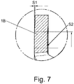
- the piston 1 also has a piston surface 1B, which is a closed circular segment that presses on the edge of the outer disk carrier 12 over its entire surface. In order to be able to adapt optimally even when the piston surface 1B or the outer disk carrier 12 is deformed, the piston surface 1B has a slight crowning 1D in order to represent an effective radius.
- This crowning is in figure 7 shown.
- the piston 1 At its axial inner diameter, the piston 1 has a piston collar 1A to center the thrust needle bearing 15 to the ball ramp 11.
- a crowning 1D' is also provided on the middle diameter of the axial needle bearing 15 on the piston collar 1A, in order to always load the axial needle bearing 15 centrally when the piston 1 is deformed.
- the thick bearing washer 16 for the needle thrust bearing 15 is used.
- the bearing washer also serves as a hardened running washer for the bearing needle.
- a spring 2 is present as a separate component, which consists of a spring ring 2B with spring fingers 2A attached thereto.
- Spring shackles 4 are attached to the outer circumference of the spring ring 2B for centering in the clutch basket.
- the piston 1 has punched openings 1C in order to be able to arrange the spring fingers 2A in such a way that the spring fingers 2A presses the thick bearing disk 16 via the piston 1 against the axial needle bearing 15 against the ball ramp 11 or preloads the piston 1 in each clutch position Maintains composite piston 1, bearing washer 16, needle thrust bearing 15 and ball ramp 11 and can be pushed back to the fully released position.
- the openings 1C are simple punched holes into which the spring fingers 2A can be snapped by bending the spring fingers 2A open, so that the piston 1 and the spring 2 form a preassembled unit, so that they can be assembled as a single unit when assembling the clutch assembly part to be assembled.
- tabs 1E remain in the piston 1 at the openings 1C, behind which the spring fingers 2A are inserted in the manner of a bayonet lock and mounted twisted.
- the spring fingers 2A are also connected to one another on the outer diameter by a spring ring 2B and, like the piston 1, have a centering diameter in the clutch basket 14 and spring shackles 4 as a torsion protection in the clutch basket 14.
- the spring 2 is additionally supported axially on the front side of the clutch basket 14 and to be able to generate the spring force for the axial needle bearing 15 .
- the axial spring function can be easily implemented by threading or bayonet lock, the coupling rigidity can be adjusted by the sheet thickness and the load on adjacent components can be optimized by crowning, i.e. the formation of a radius and a crowning.
- the spring 2 also has a crowning at the contact point 2C to the sheet metal of the piston 1 due to a deformed radius, so that the contact pressure point does not change significantly when the spring is deformed and to enable good sliding of the spring 2 to the piston 1 at the contact point 2C.
- the piston 1 has a pair of stamped teeth 3 on the outer diameter, with which it is centered in the toothing of the lamellae 14B of the clutch basket 14 and is therefore only axially displaceable in the direction of the A axis.
- the spring 2 also has spring shackles 4 on the outer diameter, on which the spring is supported axially on the open clutch basket 14 on the end face. For this support, additional small pinnacles 14A were punched out at the end of the clutch basket 14 so that the spring 2 can also be centered in the clutch basket 14 via the outer diameter.
Landscapes
- Engineering & Computer Science (AREA)
- General Engineering & Computer Science (AREA)
- Mechanical Engineering (AREA)
- Mechanical Operated Clutches (AREA)
Abstract
Kupplungsanordnung (10) mit einem Kupplungskorb (14), in dem Lamellenpakete von Außenlamellen (12') und Innenlamellen (13') von einem Innenlamellenträger (13) und einem Außenlamellenträger (12) getragen werden, und einem Kolben (1) zur Betätigung der Kupplungsanordnung (10) durch axiale Verschiebung der Außenlamellen (12') im Außenlamellenträger (12) und einer Feder (2), wobei der Kolben und die Feder aus Blechen unterschiedlicher Eigenschaften hergestellt und zu einer Baugruppe vormontiert sindClutch arrangement (10) with a clutch basket (14), in which disk packs of outer disks (12') and inner disks (13') are carried by an inner disk carrier (13) and an outer disk carrier (12), and a piston (1) for actuating the Clutch arrangement (10) by axial displacement of the outer disks (12') in the outer disk carrier (12) and a spring (2), the piston and the spring being made from metal sheets with different properties and being preassembled to form an assembly
Description
Die Erfindung betrifft eine Kupplungsanordnung mit einem Kupplungskorb, in dem Lamellenpakete von Außenlamellen und Innenlamellen von einem Innenlamellenträger und einem Außenlamellenträger getragen werden, und einem Kolben zur Betätigung der Kupplungsanordnung durch axiale Verschiebung der Außenlamellen im Außenlamellenträger und einer Feder.The invention relates to a clutch arrangement with a clutch basket in which the disk packs of outer disks and inner disks are carried by an inner disk carrier and an outer disk carrier, and a piston for actuating the clutch arrangement by axial displacement of the outer disks in the outer disk carrier and a spring.
Eine Kupplungseinrichtung umfasst üblicherweise ein Betätigungselement, das dazu eingerichtet ist, ein zugeordnetes Lamellenpaket axial zusammenzupressen, um eine Übertragung von Drehmoment über diese Kupplung zu ermöglichen. Der Kolben ist aus Sintermaterial gefertigt, der durch seine Fingerausprägung zu einer ungleichmäßiger Lamellenbelastung führt.A clutch device usually includes an actuating element which is set up to axially compress an associated disk pack in order to enable torque to be transmitted via this clutch. The piston is made of sintered material, which, due to its finger shape, leads to an uneven load on the fins.
Um die Kupplung wieder zu öffnen und den Drehmomentfluss zu unterbrechen, reicht es üblicherweise nicht aus, die axiale Anpresskraft auf das Betätigungselement zurückzunehmen. Vielmehr muss das Betätigungselement aktiv vom Lamellenpaket entfernt werden. Zu diesem Zweck ist ein elastisches Element vorgesehen, das auf das Betätigungselement wirkt. Das elastische Element ist üblicherweise als eine oder mehrere Schraubenfedern oder als Tellerfeder ausgeführt. Dabei kann eine Teileanzahl der Kupplungseinrichtung durch den Rückstellmechanismus mit allen weiteren benötigten Teilen beträchtlich erhöht sein.In order to open the clutch again and interrupt the flow of torque, it is usually not sufficient to reduce the axial contact pressure on the actuating element. Rather, the actuating element must be actively removed from the disk pack. For this purpose, an elastic element is provided which acts on the actuating element. The elastic element is usually designed as one or more helical springs or as a disc spring. In this case, the number of parts in the clutch device can be considerably increased by the restoring mechanism with all other required parts.
Eine verbesserte Ausführung findet sich in der
Sie enthält ein Betätigungsmittel für eine Kupplungseinrichtung. Sowohl das Betätigungsmittel als auch ein Außenlamellenträger sind topfförmig ausgebildet, indem sie jeweils einen ersten Abschnitt aufweisen, der sich vornehmlich in radialer Richtung erstreckt, und einen zweiten Abschnitt, der sich von der radialen Außenseite des ersten Abschnitts aus vornehmlich in axialer Richtung erstreckt. Sowohl das Betätigungsmittel als auch der Außenlamellenträger sind aus einem Blech herstellbar, insbesondere mittels Stanzen, Pressen oder Ziehen.It contains an actuating means for a clutch device. Both the actuating means and an outer disk carrier are pot-shaped in that they each have a first section that extends primarily in the radial direction and a second section that extends from the radial outside of the first section extends primarily in the axial direction. Both the actuating means and the outer disk carrier can be produced from sheet metal, in particular by means of stamping, pressing or drawing.
Am Betätigungsmittel ist ein Finger ausgestellt, der sich in radialer Richtung erstreckt. Dabei kann das am Betätigungsmittel fest anliegende Ende wahlweise radial innen oder radial außen liegen. Der Finger kann sich auch in axialer Richtung oder in einer beliebigen anderen Richtung in der Drehebene um die Drehachse erstrecken. Der Finger ist durch Stanzen und Biegen geformt. Die elastischen Eigenschaften des Fingers, sind durch die Wahl der Länge, der Breite und des Querschnittsverlaufs beeinflussbar. Normalerweise sind nicht nur einer, sondern mehrere Finger am Betätigungsmittel vorgesehen, die auf einem Umfang um die Drehachse versetzt angeordnet sind. Das elastisch aufgebaute Betätigungsmittel ist über ein Axialnadellager am angrenzenden Bauelement abgestützt.A finger is exposed on the actuating means, which extends in the radial direction. In this case, the end that rests firmly on the actuating means can optionally be located radially on the inside or radially on the outside. The finger can also extend in the axial direction or in any other direction in the plane of rotation about the axis of rotation. The finger is formed by stamping and bending. The elastic properties of the finger can be influenced by the choice of length, width and cross-section. Normally, not just one, but several fingers are provided on the actuating means, which are arranged offset on a circumference around the axis of rotation. The elastically constructed actuating means is supported on the adjacent component via an axial needle bearing.
Es ist Aufgabe der Erfindung, eine kostengünstige Lösung für Kolben und Feder bereitzustellen, die axial schmal baut, die Kupplungslamellen gleichmäßig entlang des Umfangs belastet, als elastisches Element in der Kupplungsanordnung wirkt, um die Kupplung weicher und gut regelbar zu machen, sowie zu einer gleichmäßigeren Belastung des Axialnadellagers führt.The object of the invention is to provide a cost-effective solution for the piston and spring that is axially narrow, loads the clutch plates evenly along the circumference, acts as an elastic element in the clutch arrangement, to make the clutch softer and more controllable, as well as a more even load on the axial needle bearing.
Die Aufgabe wird gelöst mit einem Kupplungsanordnung mit einem Kupplungskorb, in dem Lamellenpakete aus Außenlamellen und Innenlamellen von einem Innenlamellenträger und einem Außenlamellenträger getragen werden, und einem Kolben zur Betätigung der Kupplungsanordnung durch axiale Verschiebung der Außenlamellen und einer Feder, wobei der Kolben und die Feder aus Blechen unterschiedlicher Eigenschaften hergestellt und zu einer Baugruppe vormontiert sind.The object is achieved with a clutch arrangement with a clutch basket in which the disk packs made up of outer disks and inner disks are carried by an inner disk carrier and an outer disk carrier, and a piston for actuating the clutch arrangement by axial displacement of the outer disks and a spring, the piston and the spring being Sheets of different properties are made and preassembled into an assembly.
Der Kolben weist einen sich axial erstreckenden Kolbenbund und eine ringförmige Kolbenfläche auf, wobei eine topfartige Ausgestaltung des Kolbens vorliegt.The piston has an axially extending piston collar and an annular piston surface, with the piston having a pot-like design.
Ausgehend vom der Kolbenfläche verjüngt sich der Kolben in Richtung auf den Kolbenbund hin.Starting from the piston surface, the piston tapers in the direction of the piston collar.
Dabei weist die ringförmige Kolbenfläche eine Balligkeit auf, womit sie an dem Außenlamellenträger anliegt und Anpressdruck aufbringen kann.The ring-shaped piston surface is crowned, so that it rests against the outer disk carrier and can apply contact pressure.
Die topfartige Ausgestaltung weist eine Balligkeit auf, die axial an einem Axialnadellager als Ausrücklager angepresst ist.The pot-like configuration has a crown which is pressed axially on an axial needle bearing as a release bearing.
Der Kolben weist Zähne auf, mit denen er in der Lamellenverzahnung des Kupplungskorbs axial verschieblich geführt ist.The piston has teeth with which it is guided in an axially displaceable manner in the multi-plate toothing of the clutch basket.
Der Kolben weist Durchbrüche in der topfartigen Ausgestaltung auf, in die Federfinger der Feder ausgehend von einem ringförmigen Federring eingreifen.The piston has openings in the pot-like configuration, into which spring fingers of the spring engage, starting from an annular spring ring.
In einer Ausführung sind Laschen an den Durchbrüchen vorhanden, so dass die Federfinger mit einer Bajonettbewegung eingeführt sind.In one embodiment, there are tabs on the openings so that the spring fingers are inserted with a bayonet movement.
Die Federfinger sind an ihrem zur Achse A zeigenden Ende in Richtung auf die Lamelllenpakete hin gekrümmt und weisen eine Balligkeit auf, die an dem Kolben anliegt.The spring fingers are curved at their end pointing towards the axis A in the direction of the disk packs and have a crowning which bears against the piston.
Der Federring weist Laschen auf, die sich am Kupplungskorb in Zinnen abstützen und zentrieren.The spring ring has lugs that are supported and centered in battlements on the clutch basket.
Durch den Einsatz von zwei einfachen Blech-Stanz-Umformteilen wird ein kostengünstiges vormontierbares Federkolbensystem realisiert, das durch Wahl der Blechwandstärke und des jeweils optimalen Werkstoffes eine einstellbare Kupplungssteifigkeit ermöglicht und zu gleichmäßigen Belastungen an Lamellen und dem Axialnadellager führt.By using two simple stamped sheet metal parts, a cost-effective, pre-assembled spring-piston system is realized, which enables adjustable clutch rigidity through the selection of sheet metal wall thickness and the optimal material in each case and leads to even loads on the disks and the axial needle bearing.
-
Figur 1 zeigt eine Kupplungsanordnung offen,figure 1 shows a clutch arrangement open, -
Figur 2 zeigt eine Kupplungsanordnung geschlossen,figure 2 shows a clutch assembly closed, -
Figur 3A zeigt ein Schnittbild einer Kolben-Feder-Baugruppe,Figure 3A shows a sectional view of a piston-spring assembly, -
Figur 3B zeigt eine Aufsicht auf die Kolben-Feder-Baugruppe,Figure 3B shows a top view of the piston-spring assembly, -
Figuren 4A bis 4C zeigen eine alternative Ausführungsform der Kolben-Feder-Baugruppe,Figures 4A to 4C show an alternative embodiment of the piston-spring assembly, -
Figur 5 zeigt eine Ansicht der Kupplungsanordnung,figure 5 shows a view of the clutch arrangement, -
Figur 6 zeigt ein Detail an der Kupplungsanordnung,figure 6 shows a detail of the clutch arrangement, -
Figur 7 zeigt ein Detail in Schnittdarstellung der Balligkeit der Kolbenfläche.figure 7 shows a sectional detail of the crowning of the piston surface.
Die
Ein Kupplungskorb 14 umfasst einen Außenlamellenträger 12 und einen Innenlamellenträger 13. Der Kupplungskorb 14 ist fest mit der tragenden Welle 20 verbunden, wobei der Innenlamellenträger 13 ebenfalls durch die Welle 20 dargestellt ist.A
Das Lamellenpaket der Innenlamellen 13' sitzt somit auf der Welle 20.Der Außenlamellenträger 12 ist ein trommelartiges Gebilde, das eine axiale Zahnstruktur aufweist. Innerhalb des Außenlamellenträgers 12 sind die Außenlamellen 12' axial verschieblich gelagert. Ein Kolben 1 ist direkt mit den Außenlamellen12' angelegt oder anlegbar und wird von einer Feder 2 durchdrungen.The disk pack of the inner disks 13' is thus seated on the
Der Kolben 1 ist über eine Lagerscheibe 16 an einem Axialnadellager 15 gelagert. Eine zweiteilige Kugelrampe 11 ist Teil des Betätigungssystems.The
In den
Der Kolben 1 und die Feder 2 haben gegenläufige Anforderungen an Funktion und Konstruktion und sind nur unzureichend in einem einzigen Blechteil mit einheitlichen Werkstoffeigenschaften umsetzbar.The
Der Kolben soll hohe Druckkräfte bei vernachlässigbarer elastischer Verformung übertragen können und wird aus gut umformbaren Blechen und für hohe Steifigkeit des Kolbens mit erheblicher Wandstärke gefertigt.The piston should be able to transmit high compressive forces with negligible elastic deformation and is made of sheet metal that is easy to form and with a considerable wall thickness for high piston rigidity.
Die Rückstellfeder hingegen soll hohe Verformungen bei geringen Kräften ermöglichen, um im entlasteten Zustand die Belastung auf das Ausrücklager gering zu halten, große Wege zu ermöglichen und wird auch aus Gründen der elastischen Dauerhaltbarkeit aus Federstahl gefertigt.The return spring, on the other hand, should allow high deformations with low forces in order to keep the load on the release bearing low in the unloaded state, to allow large travels and is also made of spring steel for reasons of elastic durability.
Um beide Funktionen optimal erfüllen zu können stellt das gefügte Feder-Kolben System keinen Kompromiss, sondern eine technische Lösung dar, die beide Anforderungen mit nur zwei Blechstanzteilen optimal kombiniert.In order to be able to optimally fulfill both functions, the joined spring-piston system does not represent a compromise, but a technical solution that optimally combines both requirements with only two stamped sheet metal parts.
Ein Blechteil bildet den steifen Kolben zur Übertragung der hohen Druckkräfte bei minimaler Verformung dar und das zweite Blech aus Federstahl gibt die ideal dauerfeste Elastizität, die ein häufiges Lüftspieldurchfahren der Kupplungsanordnung über einen weiten Bereich bei geringer Kraft ermöglicht.One piece of sheet metal forms the rigid piston for transmitting the high compressive forces with minimal deformation, and the second sheet of spring steel provides the ideal, permanent elasticity, which enables the clutch assembly to run through the clearance frequently over a wide range with little force.
Der Kolben 1 besitzt am Außendurchmesser einen Zentriersitz im Kupplungskorb 14, genauer am Außenlamellenträger 12, und wird über gestanzte Zähne 3 gegen das Verdrehen im Kupplungskorb 14 gesichert. Die Zähne 3 dienen auch zur Führung in der Lamellenverzahnung des Kupplungskorbes 14 und garantieren eine lineare Verschiebung. Der Kolben 1 weist zudem eine Kolbenfläche 1B auf, die ein geschlossenes Kreissegment ist, welches ganzflächig auf den Rand des Außenlamellenträgers 12 drückt. Um sich optimal auch bei Verformungen der Kolbenfläche 1B oder des Außenlamellenträgers 12 anschmiegen zu können, weist die Kolbenfläche 1B eine leichte Balligkeit 1D auf, um einen Wirkradius darzustellen.On the outer diameter, the
Diese Balligkeit ist in
An seinem axialen Innendurchmesser besitzt der Kolben 1 einen Kolbenbund 1A, um das Axialnadellager 15 zur Kugelrampe 11 hin zu zentrieren. Ebenso ist auch eine Balligkeit 1D' am mittleren Durchmesser des Axialnadellagers 15 am Kolbenbund 1A vorgesehen, um bei einer Verformung des Kolbens 1 immer das Axialnadellager 15 zentral zu belasten.At its axial inner diameter, the
Um die ringförmige Belastung durch die Balligkeit 1D' auf das Axialnadellager 15 gleichmäßig auszugestalten, wird die dicke Lagerscheibe16 für das Axialnadellager 15 eingesetzt. Dadurch wird in jeder Kolbenposition und bei etwaigen Verformungen eine gleichmäßige, flächige Lagerbelastung der Lagernadeln realisiert. Zudem dient die Lagerscheibe als gehärtete Laufscheibe für die Nadel des Lagers.In order to make the annular load from the crowning 1D' on the needle thrust bearing 15 uniform, the
Als getrenntes Bauteil liegt eine Feder 2 vor, die aus einem Federring 2B mit daran angebrachten Federfingers 2A besteht. Am Außenumfang des Federrings 2B sind Federlaschen 4 zur Zentrierung im Kupplungskorb angebracht.A
Der Kolben 1 besitzt ausgestanzte Durchbrüche 1C, um die Federfinger 2A so anordnen zu können, dass die Federfinger 2A über den Kolben 1 die dicke Lagerscheibe 16 gegen das Axialnadellager 15 gegen die Kugelrampe 11 presst bzw. den Kolben 1 in jeder Kupplungsposition eine Vorspannung auf den Verbund Kolben 1, Lagerscheibe 16, Axialnadellager 15 und Kugelrampe 11 aufrechterhält und in die Position voll gelüftet zurückgedrückt werden kann.The
Im einfachsten Fall sind die Durchbrüche 1C einfache gestanzte Löcher, in die die Federfinger 2A durch Aufbiegen der Federfinger 2A eingeschnappt werden können, so dass der Kolben 1 und die Feder 2 eine vormontierte Einheit bilden, so dass sie in der Montage der Kupplungsanordnung wie ein einziges Teil zu montieren sind.In the simplest case, the
In einer weiterem Ausführungsform nach den
Die Federfinger 2A sind am Außendurchmesser ebenfalls durch einen Federring 2B mit einander verbunden und besitzen wie der Kolben 1 einen Zentrierdurchmesser im Kupplungskorb 14 und Federlaschen 4 als Verdreh-Sicherung im Kupplungskorb 14.The
Die Feder 2 stützt sich noch zusätzlich axial am Kupplungskorb 14 stirnseitig ab und die Federkraft zum Axialnadellager 15 erzeugen zu können.The
Um die stirnseitige Abstützung am Kupplungskorb 14 einfach zu realisieren, bietet es sich an, am Kupplungskorb 14 kleinen Zinnen 14A auszustanzen, die die Verdreh-Sicherung und die axiale Abstützung mit den Federlaschen 4 in einem realisieren.In order to simply implement the frontal support on the
Durch Einsatz von Blechumformteile kann die axiale Federfunktion durch Einfädeln bzw. Bajonettverschluss einfach realisiert werden, die Kupplungssteifigkeit durch die Blechstärke eingestellt und durch Bombierungen, das heißt die Ausprägung eines Radius und einer Ballgkeit, die Belastung angrenzender Bauteile optimiert werden.By using formed sheet metal parts, the axial spring function can be easily implemented by threading or bayonet lock, the coupling rigidity can be adjusted by the sheet thickness and the load on adjacent components can be optimized by crowning, i.e. the formation of a radius and a crowning.
Auch die Feder 2 besitzt am Berührungspunkt 2C zum Blech des Kolbens 1 eine Balligkeit durch einen umgeformten Radius, um ebenso den Anpresspunkt bei der Verformung der Feder nicht signifikant zu ändern und ein gutes Gleiten von Feder 2 zu Kolben1 im Berührungspunkt 2C zu ermöglichen.The
Der Kolben 1 besitzt am Außendurchmesser ein paar gestanzte Zähnen 3, mit denen er sich in der Lamellenverzahnung 14B des Kupplungskorb 14 zentriert und somit lediglich axial in Richtung der Achse A verschieblich ist.The
Die Feder 2 besitzt ebenfalls Federlaschen 4 am Außendurchmesser, an denen sich die Feder am offenen Kupplungskorb 14 an der Stirnseite axial abstützt. Für diese Abstützung wurde im Kupplungskorb 14 zusätzliche kleine Zinnen 14A am Ende ausgestanzt, damit sich die Feder 2 ebenso über den Außendurchmesser im Kupplungskorb 14 zentrieren kann.The
Wird der Kolben 1 durch die Kugelrampe 11 über das Axialnadellager 15 axial verschoben, entsteht in den verformten Federfingern 2A der Feder 2 eine Erhöhung der Federkraft entsprechende der Federkennlinie, die ihn wieder in die gelüftete Kolbenposition zurückschieben, wenn die Aktuierungskraft wieder abnimmt.If the
- 11
- KolbenPistons
- 1A1A
- Kolbenbundpiston collar
- 1B1B
- Kolbenflächepiston area
- 1C1C
- Durchbruchbreakthrough
- 1D, 1D'1D, 1D'
- Balligkeitencrowning
- 1E1E
- Laschetab
- 22
- FederFeather
- 2A2A
- Federfingerspring finger
- 2B2 B
- Federringspring washer
- 2C2C
- Berührungspunktpoint of contact
- 33
- Zähneteeth
- 44
- Federlaschenspring tabs
- 1010
- Kupplungsanordnungclutch assembly
- 1111
- zweiteilige Kugelrampetwo-piece ball ramp
- 1212
- Außenlamellenträgerouter disc carrier
- 12'12'
- Außenlamellenouter slats
- 1313
- Innenlamellenträgerinner disc carrier
- 1313
- Innenlamelleninner slats
- 1414
- Kupplungskorbclutch basket
- 14A14A
- Zinnenbattlements
- 14B14B
- Lamellenverzahnunglamella toothing
- 1515
- Axialnadellageraxial needle bearing
- 1616
- Lagerscheibebearing washer
Claims (7)
Applications Claiming Priority (1)
| Application Number | Priority Date | Filing Date | Title |
|---|---|---|---|
| DE102021205655.5A DE102021205655B3 (en) | 2021-06-02 | 2021-06-02 | clutch assembly |
Publications (1)
| Publication Number | Publication Date |
|---|---|
| EP4102091A1 true EP4102091A1 (en) | 2022-12-14 |
Family
ID=81648382
Family Applications (1)
| Application Number | Title | Priority Date | Filing Date |
|---|---|---|---|
| EP22172932.0A Withdrawn EP4102091A1 (en) | 2021-06-02 | 2022-05-12 | Coupling assembly |
Country Status (3)
| Country | Link |
|---|---|
| EP (1) | EP4102091A1 (en) |
| CN (1) | CN115435022A (en) |
| DE (1) | DE102021205655B3 (en) |
Citations (3)
| Publication number | Priority date | Publication date | Assignee | Title |
|---|---|---|---|---|
| DE102015205832A1 (en) | 2015-03-31 | 2016-10-06 | Schaeffler Technologies AG & Co. KG | Axial multi-plate clutch |
| DE102018122696A1 (en) * | 2018-09-17 | 2020-03-19 | Schaeffler Technologies AG & Co. KG | Coupling device and hybrid module with a coupling device |
| DE102019124190A1 (en) | 2019-09-10 | 2021-03-11 | Schaeffler Technologies AG & Co. KG | Separating clutch with return spring reaching through and behind the pressure pot with positive locking, drive train and method for assembling a separating clutch |
Family Cites Families (2)
| Publication number | Priority date | Publication date | Assignee | Title |
|---|---|---|---|---|
| DE10126779B4 (en) | 2001-06-01 | 2011-03-17 | Zf Sachs Ag | Pressure plate assembly |
| DE102009057425A1 (en) | 2009-06-24 | 2010-12-30 | Zf Friedrichshafen Ag | Clutch arrangement i.e. wet-running clutch, for use in hybrid drive system of vehicle, has bearing arrangements permitting clearance between housing and assembly and between housing and shaft element, respectively |
-
2021
- 2021-06-02 DE DE102021205655.5A patent/DE102021205655B3/en active Active
-
2022
- 2022-05-12 EP EP22172932.0A patent/EP4102091A1/en not_active Withdrawn
- 2022-05-31 CN CN202210606476.4A patent/CN115435022A/en active Pending
Patent Citations (3)
| Publication number | Priority date | Publication date | Assignee | Title |
|---|---|---|---|---|
| DE102015205832A1 (en) | 2015-03-31 | 2016-10-06 | Schaeffler Technologies AG & Co. KG | Axial multi-plate clutch |
| DE102018122696A1 (en) * | 2018-09-17 | 2020-03-19 | Schaeffler Technologies AG & Co. KG | Coupling device and hybrid module with a coupling device |
| DE102019124190A1 (en) | 2019-09-10 | 2021-03-11 | Schaeffler Technologies AG & Co. KG | Separating clutch with return spring reaching through and behind the pressure pot with positive locking, drive train and method for assembling a separating clutch |
Also Published As
| Publication number | Publication date |
|---|---|
| CN115435022A (en) | 2022-12-06 |
| DE102021205655B3 (en) | 2022-10-20 |
Similar Documents
| Publication | Publication Date | Title |
|---|---|---|
| EP1832769A2 (en) | Friction coupling | |
| EP2670994B1 (en) | Clutch device | |
| DE2820412A1 (en) | COUPLING | |
| DE102012222269A1 (en) | friction clutch | |
| DE19547558A1 (en) | Friction clutch with spring supported decoupling force | |
| DE4326404B4 (en) | Friction clutch device, in particular for a motor vehicle, and elastic diaphragm spring for such a clutch device | |
| DE2750334C2 (en) | ||
| DE112014001037B4 (en) | friction clutch | |
| EP3137781B1 (en) | Cover assembly for a friction clutch | |
| DE102011003030B4 (en) | Clutch disk for a friction clutch of a motor vehicle | |
| EP3332140B1 (en) | Friction clutch device | |
| DE19982986B4 (en) | Friction clutch with a wear adjusting device for the friction linings, in particular for motor vehicles | |
| DE102021205655B3 (en) | clutch assembly | |
| EP1647729A2 (en) | Coupling device for multiple disc clutch | |
| EP3085979A1 (en) | Plate spring with integrated support spring sections | |
| EP3565984B1 (en) | Friction clutch | |
| DE102019125989B4 (en) | coupling device | |
| DE102017130853B4 (en) | coupling device | |
| DE102012224001A1 (en) | Clutch device i.e. single clutch, for powertrain of motor car, has coil comprising embossings, and lever element supported by portions and coil, where edges of embossings are brought in contact with portions or tolerance-afflicted system | |
| EP1729024B1 (en) | Clutch disc arrangement for a multi-disc friction clutch | |
| DE102012210716A1 (en) | Clamping spring for force-controlled readjusting device of dual-clutch of motor car, has attachment element fixed with pad to limit movement of spring to cover, where spring is extended along circumferential direction around certain angle | |
| DE19982988B3 (en) | Friction clutch with a Verschleissnachstellvorrichtung for friction linings, especially for Kaftfahrzeuge | |
| DE102014221396B3 (en) | Pressure plate assembly for a coupling device without leaf springs and coupling device | |
| DE102017126216A1 (en) | coupling device | |
| DE19963023A1 (en) | Clutch disc arrangement for a multi-disc clutch |
Legal Events
| Date | Code | Title | Description |
|---|---|---|---|
| PUAI | Public reference made under article 153(3) epc to a published international application that has entered the european phase |
Free format text: ORIGINAL CODE: 0009012 |
|
| STAA | Information on the status of an ep patent application or granted ep patent |
Free format text: STATUS: THE APPLICATION HAS BEEN PUBLISHED |
|
| STAA | Information on the status of an ep patent application or granted ep patent |
Free format text: STATUS: REQUEST FOR EXAMINATION WAS MADE |
|
| AK | Designated contracting states |
Kind code of ref document: A1 Designated state(s): AL AT BE BG CH CY CZ DE DK EE ES FI FR GB GR HR HU IE IS IT LI LT LU LV MC MK MT NL NO PL PT RO RS SE SI SK SM TR |
|
| 17P | Request for examination filed |
Effective date: 20221117 |
|
| RBV | Designated contracting states (corrected) |
Designated state(s): AL AT BE BG CH CY CZ DE DK EE ES FI FR GB GR HR HU IE IS IT LI LT LU LV MC MK MT NL NO PL PT RO RS SE SI SK SM TR |
|
| GRAP | Despatch of communication of intention to grant a patent |
Free format text: ORIGINAL CODE: EPIDOSNIGR1 |
|
| STAA | Information on the status of an ep patent application or granted ep patent |
Free format text: STATUS: GRANT OF PATENT IS INTENDED |
|
| INTG | Intention to grant announced |
Effective date: 20230609 |
|
| STAA | Information on the status of an ep patent application or granted ep patent |
Free format text: STATUS: THE APPLICATION IS DEEMED TO BE WITHDRAWN |
|
| 18D | Application deemed to be withdrawn |
Effective date: 20231020 |