EP4101769B1 - Umkehrschub in einem mehrmotorigen propellerflugzeug - Google Patents
Umkehrschub in einem mehrmotorigen propellerflugzeug Download PDFInfo
- Publication number
- EP4101769B1 EP4101769B1 EP22183072.2A EP22183072A EP4101769B1 EP 4101769 B1 EP4101769 B1 EP 4101769B1 EP 22183072 A EP22183072 A EP 22183072A EP 4101769 B1 EP4101769 B1 EP 4101769B1
- Authority
- EP
- European Patent Office
- Prior art keywords
- propeller
- engine
- reverse thrust
- controller
- engine controller
- Prior art date
- Legal status (The legal status is an assumption and is not a legal conclusion. Google has not performed a legal analysis and makes no representation as to the accuracy of the status listed.)
- Active
Links
Images




Classifications
-
- B—PERFORMING OPERATIONS; TRANSPORTING
- B64—AIRCRAFT; AVIATION; COSMONAUTICS
- B64C—AEROPLANES; HELICOPTERS
- B64C11/00—Propellers, e.g. of ducted type; Features common to propellers and rotors for rotorcraft
- B64C11/30—Blade pitch-changing mechanisms
-
- B—PERFORMING OPERATIONS; TRANSPORTING
- B64—AIRCRAFT; AVIATION; COSMONAUTICS
- B64D—EQUIPMENT FOR FITTING IN OR TO AIRCRAFT; FLIGHT SUITS; PARACHUTES; ARRANGEMENT OR MOUNTING OF POWER PLANTS OR PROPULSION TRANSMISSIONS IN AIRCRAFT
- B64D31/00—Power plant control systems; Arrangement of power plant control systems in aircraft
- B64D31/02—Initiating means
- B64D31/06—Initiating means actuated automatically
- B64D31/12—Initiating means actuated automatically for equalising or synchronising power plants
Definitions
- the present disclosure relates generally to propeller control, and more particularly to the production of reverse thrust via variable pitch propellers.
- Multi-engine propeller aircraft consists of two or more so-called “powerplants”, each composed of two principal and distinct components: an engine and a propeller.
- a multi-engine propeller aircraft will consist of any number of powerplants, which can be evenly disposed on either side of a fuselage of the aircraft and/or within the fuselage itself. Control of the engines and propellers can be effected separately or jointly via controls available within a cockpit or other control structure of the aircraft.
- the powerplants produce reverse thrust - that is to say, thrust which generally opposes the heading of the aircraft.
- this can be accomplished by altering a pitch of the propeller blade, also referred to as a propeller blade angle.
- a pitch of the propeller blade also referred to as a propeller blade angle.
- the thrust produced by rotation of the propeller can be reversed.
- the transition from forward- to reverse-thrust propeller blade angles can require synchronisation of the transition for all propellers of the aircraft. If this transition is not sufficiently synchronized, the reverse thrust may not be produced evenly, which can result in yawing or other undesirable behaviours for the aircraft.
- Traditional approaches require careful pilot coordination, but are subject to pilot error, and can be complex.
- EP 3 018 054 A1 discloses a prior art method for controlling an aircraft propeller system during thrust reversal.
- a system for producing reverse thrust in a multi-engine aircraft comprising a first engine controller for a first engine of the aircraft, the first engine controller configured for: obtaining a first power request for the first engine for producing reverse thrust; and determining a first blade angle for a first propeller, the first propeller coupled to the first engine.
- the system further comprises a second engine controller for a second engine of the aircraft, the second engine controller communicatively coupled to the first engine controller and configured for: obtaining a second power request for the second engine for producing reverse thrust; determining a second blade angle for a second propeller, the second propeller coupled to the second engine; obtaining, from the first engine controller, the first power request for the first engine and the first blade angle for the first propeller; and when the first power request is indicative of a request for producing reverse thrust and when the first and second blade angles are beyond a predetermined threshold, commanding, via the first engine controller, the first engine to produce reverse thrust based on the second power request.
- a second engine controller for a second engine of the aircraft, the second engine controller communicatively coupled to the first engine controller and configured for: obtaining a second power request for the second engine for producing reverse thrust; determining a second blade angle for a second propeller, the second propeller coupled to the second engine; obtaining, from the first engine controller, the first power request for the first engine and the first
- an aircraft 100 having a fuselage 110, a pair of wings 140 (or more), engines 150, propellers 160, and a tail 170.
- the aircraft 100 may be any suitable aircraft - such as corporate, private, commercial, or the like - which includes multiple engines 150 and propellers 160. Collectively, an engine-propeller pair may be referred to as a "powerplant”.
- the fuselage 110 has a cockpit 120, which can be positioned at any suitable location on the aircraft 100, for example at a front portion of the fuselage 110.
- the cockpit 120 is configured for accommodating one or more pilots who control the aircraft 100 by way of one or more operator controls.
- the operator controls can include any suitable number of pedals, yokes, steering wheels, centre sticks, flight sticks, levers, knobs, switches, and the like. Although two engines 150 are illustrated, it should be understood that the aircraft 100 can have any suitable number of engines, for example four, six, eight, and the like.
- the engines 150 effect rotational motion in the propellers 160, which in turn produce thrust via propeller blades, causing the aircraft 100 to be displaced.
- the propellers blades are configured for assuming a propeller blade angle, which varies both the magnitude and direction of the thrust produced by the propellers 160.
- the propeller blade angle is indicative of an orientation of the blades of the propellers 160 relative to a particular reference angle.
- a positive propeller blade angle can cause the propellers 160 to produce forward thrust, that is to say, thrust which displaces the aircraft 100 in a direction aligned with the heading of the aircraft 100.
- Increasing the propeller blade angle to a larger positive value can further increase the amount of forward thrust produced.
- a negative propeller blade angle can cause the propellers 160 to produce reverse thrust, which is substantially opposite positive thrust, and a larger negative value for the propeller blade angle can cause an increase in the amount of reverse thrust produced.
- the aircraft 100 can experience unwanted behaviors. For example, for an aircraft like the aircraft 100 in Figure 1 , if the engine 150 on one side of the aircraft 100 transitions to producing reverse thrust later than the engine 150 on the other side of the aircraft 100, the aircraft 100 can yaw, which can complicate the ability of an operator of the aircraft 100 to maintain a desired trajectory for the aircraft.
- the aircraft is composed of two powerplants 210, 260, each being constituted of an engine 212, 262, and a propeller 214, 264.
- the powerplants 210, 260 are controlled by respective powerplant controllers 220, 270, each being constituted of an engine controller 222, 272, and a propeller controller 224, 274.
- the powerplant controllers 220, 270 are configured for being communicatively coupled to one another.
- the engine controllers 222 and 272 are communicatively coupled.
- Each one of the engine controllers 222, 272 is communicatively coupled to the propeller controller of the other powerplant: the engine controller 222 is communicatively coupled to the propeller controller 274, and the engine controller 272 is communicatively coupled to the propeller controller 224. Still other embodiments are considered.
- the engine controller 222 is configured for exacting control of the engine 212
- the propeller controller 224 is configured for exacting control of the propeller 214.
- the engine 212 and the propeller 214 can be provided with one or more sensors for providing information to their respective controllers 222, 224. These sensors can include speed sensors, torque sensors, acceleration sensors, propeller blade angle sensors, and the like.
- the coupling between the engine 212 and the engine controller 222, and between the propeller 214 and the propeller 224, can be effected in any suitable way, using any suitable wired, wireless, or mixed communication techniques.
- the engine controller 222 is configured for receiving a first power request from a pilot input 202.
- the pilot input 202 can be a power lever or similar control device, and the first power request can take the form of a power lever angle.
- the power lever is provided with a plurality of settings, including a maximum takeoff setting, a flight idle setting, a ground idle setting, and a reverse thrust setting, each associated with respective power lever angles.
- the pilot input 202 can provide a signal to the engine controller 222 which indicates the power lever angle, and the engine controller can interpret the signal to determine one or more engine settings for the engine 212.
- the propeller controller 224 and the engine controller 222 are configured for exchanging information.
- the propeller controller 224 can obtain, from the propeller 214, a value for the blade angle for the propeller 214, and can provide the engine controller 222 with this value.
- Other information can also be exchanged between the engine controller 222 and the propeller controller 224, as appropriate.
- each of the interactions discussed hereinabove with respect to the powerplant 210, the powerplant controller 220, and the pilot input 202 are analogous to the interactions which can take place between the powerplant 260, the powerplant controller 270, and the pilot input 252.
- the pilot inputs 202, 252 are separate inputs, for example separate power levers.
- the pilot inputs 202, 252 can each represent multiple inputs, for instance both a power lever and a propeller-related lever, which can be used to adjust the propeller blade angle, to adjust a propeller speed setting, to command the propeller 214 or 264 to feather, , and the like.
- one or both of the pilot inputs 202, 252 include buttons, switches, dials, or other discrete-type input mechanisms. Also, although the foregoing discussion has focused on the aircraft 100 which includes two powerplants 210, 260, it should be understood that the methods and systems described herein can be applicable to aircraft which include more than two powerplants, in cases where each of the powerplants is provided with an individual powerplant controller, or in any other suitable situation.
- the engine controller 222 can receive, via the pilot input 202, a request for the powerplant 210 to produce reverse thrust.
- a request for the powerplant 210 to produce reverse thrust For example, in cases in which the pilot input 202 is a power lever, a signal indicating that the power lever angle is set at a "reverse thrust” setting can be received by the engine controller 222. In another example, the signal indicates that the power lever angle is set at a "ground idle” setting. Other settings are also considered.
- the request to produce reverse thrust is based on a transition from the "ground idle” setting to a "reverse thrust” setting. In still further embodiments, the request to produce reverse thrust involves a request to increase an amount of thrust produced by the powerplant 210, for example an increase in the amount of reverse thrust to be produced. Still other embodiments of the request to produce reverse thrust are considered.
- the blades of the propeller 214 are caused to transition to a blade angle suitable for producing reverse thrust (herein referred to as a "negative blade angle", although other nomenclatures are also considered).
- the transition to the negative blade angle for the blades of the propeller 214 can be effected via the propeller controller 224, which can command actuators or other systems within the propeller 214 to cause the blades of the propeller 214 to assume the negative blade angle.
- the transition to the negative blade angle for the blades of the propeller 214 should be substantially synchronous with a transition to the negative blade angle for the blades of the propeller 264.
- the blades of both propeller 214, 264 do not need to transition to the same negative blade angle.
- the blades of the propellers 214, 264 can be caused to transition to different negative blade angles substantially synchronously, and mismatches between the negative blade angles can be tolerated.
- a mismatch between the negative blade angles for propellers 214, 264 can be countered by commanding a tail rudder of the aircraft 100 to compensate for the mismatch.
- Other approaches are also considered.
- the engine controller 222 obtains the request to produce reverse thrust, and also obtains the propeller blade angle for the propeller 214.
- the propeller controller 224 can provide the propeller blade angle for the propeller 214 to the engine controller 222 in a substantially continuous and/or real-time fashion.
- the engine controller 222 can periodically request the propeller blade angle for the propeller 214 from the propeller controller 224, or can request the propeller blade angle for the propeller 214 in response to a particular event, for instance in response to receiving the request to produce reverse thrust.
- the engine controller 222 obtains, from the powerplant controller 270, a propeller blade angle for the propeller 264 and an indication of whether the engine controller 272 has also received a request to produce reverse thrust. In order to ensure synchronicity between the propellers 214 and 264, the engine controller 222 and 272 will wait until both engine controllers 222, 272 have been requested to produce reverse thrust, and until the propeller blades for both propellers 214, 264 are at a blade angle suitable for producing reverse thrust, for example beyond a predetermined threshold value.
- the engine controller 222 evaluates whether the propeller blade angle for both propellers 214, 264 is beyond the predetermined threshold value.
- the threshold value can be indicative of an angle beyond which is it deemed safe to begin the production of reverse thrust.
- the threshold value can be associated with a "low beta" angle for blades of the propellers 214, 264.
- the threshold value is substantially similar to a neutral angle for the blades of the propellers 214, 264. It should be noted that the term "beyond”, in this context, can be understood to be above the threshold value, below the threshold value, approximately at the threshold value, or any other indication that the blade angle of the propellers 214, 264, are suitable for producing reverse thrust.
- the engine controller 222 can implement the request to produce reverse thrust. This can include commanding the engine 212 to increase an output torque to the propeller 214, instructing the propeller controller 224 to command actuators within the propeller 214 to rotate the blades of the propeller 214, for example to a larger negative blade angle, and the like.
- the engine controller 272 can perform similar operations, including: obtaining a request to produce reverse thrust from the pilot input 252, validating that the engine controller 222 has also received a request to produce reverse thrust, and validating that the blades of the propellers 214, 264 are at respective propeller blade angles that are beyond the threshold value. Once the engine controller 272 has ascertained that these conditions are met, the engine controller 272 can implement the request to produce reverse thrust, which can include commanding the engine 262 to increase an output torque to the propeller 264, instructing the propeller controller 274 to command actuators within the propeller 264 to rotate the blades of the propeller 264, for example to a larger negative blade angle, and the like.
- each engine controller 222, 272 independently verifies that both powerplants 210, 260 are prepared for producing reverse thrust before implementing the request to produce reverse thrust.
- This synchronization of the request to produce reverse thrust between the engine controllers 222, 272 can contribute to reducing undesirable yawing or other behaviours.
- the engine controllers 222, 272 are communicatively coupled to one another, allowing for cross-talk therebetween, there is no need for a central controller or avionics system to arbitrate the requests for producing reverse thrust.
- the powerplant controllers 220, 270 are replaced with powerplant controllers 230, 280, each composed of a unified controller 232, 282.
- the unified controllers 232, 282 are configured for implementing the functionality of both an engine controller and a propeller controller: for example, the unified controller 232 can implement the functionality of the engine controller 222 and of the propeller controller 234.
- the powerplant controllers 230, 280 are communicatively coupled, for example by communicatively coupling the unified controllers 232, 282.
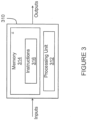
- one or more of the engine controllers 210, 260, the propeller controllers 220, 270, and/or the unified controllers 230, 280 may be implemented by a computing device 310, comprising a processing unit 312 and a memory 314 which has stored therein computer-executable instructions 316.
- the processing unit 312 may comprise any suitable devices configured to implement the system 300 such that instructions 316, when executed by the computing device 310 or other programmable apparatus, may cause the functions/acts/steps of the method 400 as described herein to be executed.
- the processing unit 312 may comprise, for example, any type of general-purpose microprocessor or microcontroller, a digital signal processing (DSP) processor, a central processing unit (CPU), an integrated circuit, a field programmable gate array (FPGA), a reconfigurable processor, other suitably programmed or programmable logic circuits, or any combination thereof.
- DSP digital signal processing
- CPU central processing unit
- FPGA field programmable gate array
- reconfigurable processor other suitably programmed or programmable logic circuits, or any combination thereof.
- the memory 314 may comprise any suitable known or other machine-readable storage medium.
- the memory 314 may comprise non-transitory computer readable storage medium, for example, but not limited to, an electronic, magnetic, optical, electromagnetic, infrared, or semiconductor system, apparatus, or device, or any suitable combination of the foregoing.
- the memory 314 may include a suitable combination of any type of computer memory that is located either internally or externally to device, for example random-access memory (RAM), read-only memory (ROM), compact disc read-only memory (CDROM), electro-optical memory, magneto-optical memory, erasable programmable read-only memory (EPROM), and electrically-erasable programmable read-only memory (EEPROM), Ferroelectric RAM (FRAM) or the like.
- Memory 314 may comprise any storage means (e.g., devices) suitable for retrievably storing machine-readable instructions 316 executable by processing unit 312.
- the computing device 310 can include one or more full-authority digital engine controls (FADEC), one or more propeller electronic control (PEC) units, and the like.
- FADEC full-authority digital engine controls
- PEC propeller electronic control
- the engine controllers 210, 260 are implemented as dual-channel FADECs.
- the engine controllers 210, 260 are implemented as two separate single-channel FADECs.
- the propeller controllers 220, 270 are implemented as dual-channel PECs, or as two single-channel PECs, or any suitable combination thereof.
- the unified controllers 230, 280 can be implemented as any suitable combination of FADECs, PECs, and/or any other suitable control devices.
- a first power request is obtained at a first engine controller, for example the engine controller 222.
- the first power request can be indicative of a request for the engine 212, or the powerplant 210 generally, to produce reverse thrust.
- the first power request can be obtained by the first engine controller in any suitable way, for example from an avionics system, from a pilot input, for example pilot inputs 202, 252, and the like.
- a first blade angle for a first propeller can be determined at the engine controller 222.
- the engine controller 222 can determine the first blade angle by requesting information from a propeller controller, for example the propeller controller 224.
- the engine controller 222 can obtain the first blade angle from a sensor associated with the propeller 214.
- the engine controller can be a unified controller, for example the unified controller 232, which can have already obtained the first blade angle for the propeller 214. Still other embodiments are considered.
- a second power request and a second blade angle are obtained at the first engine controller from a second engine controller, for example the engine controller 272.
- the second power request can be indicative of a request to produce reverse thrust for a second engine, for example the engine 262, or the powerplant 260 generally.
- the engine controller 272 can obtain the second power request and the second blade angle in any suitable way, and can provide them in turn to the engine controller 222 in any suitable fashion.
- the first power request and the first propeller blade angle can be provided to the second engine controller, e.g. engine controller 272, for example by the engine controller 222.
- the engine controller 272 can implement the same method 400, to ensure synchronicity when producing reverse thrust in the aircraft 100.
- the engine 212 is commanded to produce reverse thrust, for example via the engine controller 222.
- commanding the engine 212 to produce reverse thrust includes a command to increase a level of thrust production of the engine 212.
- the engine controller 222 instructs the propeller controller 224 to command actuators of the propeller 214 to rotate the blades of the propeller 214 to a negative blade angle.
- the unified controller 232 commands the actuators of the propeller 214 to rotate the blades of the propeller 214 to a negative blade angle. Still other embodiments are considered.
- the control system 500 is composed of first and second propeller control modules 510, 560, and is configured for receiving inputs associated with a power lever angle (PLA) via inputs 502, 552, and associated with a blade angle via inputs 504, 554.
- PPA power lever angle
- the control module 510 is composed of first and second propeller controllers 512, 514, illustrated here as belonging to first and second channels (CH1, CH2), and a propeller pitch actuator 516. Although the embodiment shown in Figure 5 uses a dual-channel approach, which can provide additional redundancy, it should be understood that a single-channel approach is also considered.
- the control module 560 is composed of first and second propeller controllers 562, 564, belonging to first and second channels (CH1, CH2) and a propeller pitch actuator 566.
- the PLA 502, 552 and blade angle 504, 554 inputs are shown as being provided substantially directly to the propeller controllers 512, 514, but other embodiments are also considered. For example, the PLA 502, 552 and blade angle 504, 554 inputs can be provided to the propeller controllers 512, 514 via engine controllers, or any other suitable intermediary.
- the propeller controllers 512, 514 are configured for each receiving the PLA and blade angle for a first engine and first propeller via inputs 502, 504, and the propeller controllers 562, 564 are configured for each receiving the PLA and blade angle for a second engine and second propeller via inputs 552, 554.
- the propeller controllers 512, 514, 562, 564 are communicatively coupled to one another on a per-channel basis in order to provide cross-talk between the propeller controllers 512, 514, 562, 564.
- propeller controllers 512, 562 can be communicatively coupled together
- propeller controllers 514, 564 can be communicatively coupled together.
- the propeller controllers 512, 562, and 514, 564 can exchange information relating to received request for producing reverse thrust, propeller blade angles, and the like, in order to ensure the synchronized production of reverse thrust in the aircraft 100.
- the methods and systems for producing reverse thrust in a multi-engine propeller aircraft described herein may be implemented in a high level procedural or object oriented programming or scripting language, or a combination thereof, to communicate with or assist in the operation of a computer system, for example the computing device 300.
- the methods and systems described herein may be implemented in assembly or machine language.
- the language may be a compiled or interpreted language.
- Program code for implementing the methods and systems described herein may be stored on a storage media or a device, for example a ROM, a magnetic disk, an optical disc, a flash drive, or any other suitable storage media or device.
- the program code may be readable by a general or special-purpose programmable computer for configuring and operating the computer when the storage media or device is read by the computer to perform the procedures described herein.
- Embodiments of the methods and systems described herein may also be considered to be implemented by way of a non-transitory computer-readable storage medium having a computer program stored thereon.
- the computer program may comprise computer-readable instructions which cause a computer, or in some embodiments the processing unit 312 of the computing device 310, to operate in a specific and predefined manner to perform the functions described herein.
- Computer-executable instructions may be in many forms, including program modules, executed by one or more computers or other devices.
- program modules include routines, programs, objects, components, data structures, etc., that perform particular tasks or implement particular abstract data types.
- functionality of the program modules may be combined or distributed as desired in various embodiments.
Landscapes
- Engineering & Computer Science (AREA)
- Aviation & Aerospace Engineering (AREA)
- Toys (AREA)
- Control Of Turbines (AREA)
- Operation Control Of Excavators (AREA)
- Combined Controls Of Internal Combustion Engines (AREA)
Claims (6)
- System (500) zum Erzeugen von Umkehrschub in einem mehrmotorigen Flugzeug (100), umfassend:
eine erste Triebwerkssteuerung (222) für ein erstes Triebwerk (212) des Flugzeugs (100), wobei die erste Triebwerkssteuerung (222) zu Folgendem konfiguriert ist:Erlangen einer ersten Leistungsanforderung für das erste Triebwerk (212) zur Erzeugung von Umkehrschub; undBestimmen eines ersten Blattwinkels für einen ersten Propeller (214), wobei der erste Propeller (214) mit dem ersten Triebwerk (212) gekoppelt ist; undeine zweite Triebwerkssteuerung (272) für ein zweites Triebwerk (262) des Flugzeugs (100), wobei die zweite Triebwerkssteuerung (272) kommunikativ mit der ersten Triebwerkssteuerung (222) gekoppelt und zu Folgendem konfiguriert ist:Erlangen einer zweiten Leistungsanforderung für das zweite Triebwerk (262) zur Erzeugung von Umkehrschub;Bestimmen eines zweiten Blattwinkels für einen zweiten Propeller (264), wobei der zweite Propeller (264) mit dem zweiten Triebwerk (262) gekoppelt ist;Erlangen, von der ersten Triebwerkssteuerung (222), der ersten Leistungsanforderung für das erste Triebwerk (212) und des ersten Blattwinkels für den ersten Propeller (214); undwenn die erste Leistungsanforderung eine Anforderung zum Erzeugen von Umkehrschub angibt und wenn der erste und der zweite Blattwinkel über einem vorbestimmten Grenzwert liegen, Anweisen, über die erste Triebwerkssteuerung (222), des ersten Triebwerks (212), Umkehrschub auf Grundlage der zweiten Leistungsanforderung zu erzeugen. - System nach Anspruch 1, wobei die erste und zweite Leistungsanforderung auf einem jeweiligen ersten und zweiten Leistungshebelwinkel für das erste und das zweite Triebwerk (212, 262) basieren.
- System nach Anspruch 2, wobei der erste und der zweite Leistungshebelwinkel eine Bodenleerlaufposition angeben.
- System nach Anspruch 2, wobei der erste und der zweite Leistungshebelwinkel eine Umkehrposition angeben.
- System nach einem der vorhergehenden Ansprüche, wobei, wenn der erste und der zweite Blattwinkel über einem vorbestimmten Grenzwert liegen, die zweite Triebwerkssteuerung (272) dazu konfiguriert ist, über die erste Triebwerkssteuerung (222) eine Änderung des ersten Blattwinkels anzuweisen, um so den ersten Propeller (214) dazu zu veranlassen, Umkehrschub zu erzeugen.
- System nach einem der vorhergehenden Ansprüche, wobei der erste Blattwinkel sich von dem zweiten Blattwinkel unterscheidet.
Applications Claiming Priority (2)
| Application Number | Priority Date | Filing Date | Title |
|---|---|---|---|
| US16/159,970 US11691748B2 (en) | 2018-10-15 | 2018-10-15 | Reverse thrust in multi-engine propeller aircraft |
| EP19202769.6A EP3640141B1 (de) | 2018-10-15 | 2019-10-11 | Umkehrschub in einem mehrmotorigen propellerflugzeug |
Related Parent Applications (2)
| Application Number | Title | Priority Date | Filing Date |
|---|---|---|---|
| EP19202769.6A Division-Into EP3640141B1 (de) | 2018-10-15 | 2019-10-11 | Umkehrschub in einem mehrmotorigen propellerflugzeug |
| EP19202769.6A Division EP3640141B1 (de) | 2018-10-15 | 2019-10-11 | Umkehrschub in einem mehrmotorigen propellerflugzeug |
Publications (2)
| Publication Number | Publication Date |
|---|---|
| EP4101769A1 EP4101769A1 (de) | 2022-12-14 |
| EP4101769B1 true EP4101769B1 (de) | 2024-04-10 |
Family
ID=68280867
Family Applications (2)
| Application Number | Title | Priority Date | Filing Date |
|---|---|---|---|
| EP22183072.2A Active EP4101769B1 (de) | 2018-10-15 | 2019-10-11 | Umkehrschub in einem mehrmotorigen propellerflugzeug |
| EP19202769.6A Active EP3640141B1 (de) | 2018-10-15 | 2019-10-11 | Umkehrschub in einem mehrmotorigen propellerflugzeug |
Family Applications After (1)
| Application Number | Title | Priority Date | Filing Date |
|---|---|---|---|
| EP19202769.6A Active EP3640141B1 (de) | 2018-10-15 | 2019-10-11 | Umkehrschub in einem mehrmotorigen propellerflugzeug |
Country Status (5)
| Country | Link |
|---|---|
| US (1) | US11691748B2 (de) |
| EP (2) | EP4101769B1 (de) |
| CN (1) | CN111038711B (de) |
| CA (1) | CA3058340A1 (de) |
| PL (2) | PL3640141T3 (de) |
Family Cites Families (11)
| Publication number | Priority date | Publication date | Assignee | Title |
|---|---|---|---|---|
| US2731094A (en) | 1951-11-27 | 1956-01-17 | Curtiss Wright Corp | Propeller unreversing system |
| US4934825A (en) * | 1987-12-22 | 1990-06-19 | United Technologies Corporation | Propeller phase control apparatus |
| US4958289A (en) | 1988-12-14 | 1990-09-18 | General Electric Company | Aircraft propeller speed control |
| US5315819A (en) * | 1991-09-17 | 1994-05-31 | Allied-Signal Inc. | Power management system for turbine engines |
| US5165240A (en) * | 1991-09-18 | 1992-11-24 | Allied-Signal Inc. | Method for matching engine torques for multiple engine aircraft |
| US20120087792A1 (en) * | 2010-10-12 | 2012-04-12 | Clipper Windpower, Inc. | Emergency feather rate limit with proportionality to operating pitch angle and energy storage voltage |
| FR2967397B1 (fr) | 2010-11-16 | 2012-11-16 | Snecma | Dispositif de passage d'une helice en reverse comportant un actuateur agissant sur un maneton |
| US20140169970A1 (en) * | 2012-12-18 | 2014-06-19 | Michael A. Celentano | Attached duct propeller system |
| US9821901B2 (en) | 2013-11-21 | 2017-11-21 | Pratt & Whitney Canada Corp. | System and method for electronic propeller blade angle position feedback |
| EP3018054B1 (de) * | 2014-11-07 | 2019-01-02 | Airbus Defence and Space, S.A. | Verfahren zur Steuerung eines Flugzeugpropellersystems während der Schubumkehr |
| US10059432B1 (en) * | 2017-02-22 | 2018-08-28 | Pratt & Whitney Canada Corp. | Single lever control in twin turbopropeller aircraft |
-
2018
- 2018-10-15 US US16/159,970 patent/US11691748B2/en active Active
-
2019
- 2019-10-09 CA CA3058340A patent/CA3058340A1/en active Pending
- 2019-10-11 PL PL19202769.6T patent/PL3640141T3/pl unknown
- 2019-10-11 EP EP22183072.2A patent/EP4101769B1/de active Active
- 2019-10-11 PL PL22183072.2T patent/PL4101769T3/pl unknown
- 2019-10-11 EP EP19202769.6A patent/EP3640141B1/de active Active
- 2019-10-15 CN CN201910978263.2A patent/CN111038711B/zh active Active
Also Published As
| Publication number | Publication date |
|---|---|
| CA3058340A1 (en) | 2020-04-15 |
| US11691748B2 (en) | 2023-07-04 |
| EP3640141B1 (de) | 2022-08-10 |
| EP4101769A1 (de) | 2022-12-14 |
| EP3640141A1 (de) | 2020-04-22 |
| US20200115063A1 (en) | 2020-04-16 |
| PL4101769T3 (pl) | 2024-06-10 |
| PL3640141T3 (pl) | 2022-12-05 |
| CN111038711B (zh) | 2024-08-27 |
| CN111038711A (zh) | 2020-04-21 |
Similar Documents
| Publication | Publication Date | Title |
|---|---|---|
| US11377222B2 (en) | Power management between a propulsor and a coaxial rotor of a helicopter | |
| US9727059B2 (en) | Independent speed and attitude control for a rotary wing aircraft | |
| EP3357810B1 (de) | Systeme zur antizipation des energiebedarfs für drehflügler | |
| US10059432B1 (en) | Single lever control in twin turbopropeller aircraft | |
| US8777152B2 (en) | Method and an aircraft provided with a swiveling tail rotor | |
| EP3126231B1 (de) | Höhenruderlastreduzierungssteuerung für ein drehflügelflugzeug | |
| EP3326911B1 (de) | Rotordrehzahlsteuerung mit vorwärtsgekoppeltem rotordrehzahlbefehl | |
| EP3647568B1 (de) | Selbstdrosselndes steuersystem an turbopropellergetriebenen flugzeugen | |
| US10562609B2 (en) | High trim demand relief | |
| CN114275148B (zh) | 飞行器的控制方法、系统、飞行器及计算设备 | |
| EP3640141B1 (de) | Umkehrschub in einem mehrmotorigen propellerflugzeug | |
| US12409929B2 (en) | Aircraft pitch control system with electronically geared elevator | |
| EP3527495B1 (de) | Luftwiderstandsteuerungskonfiguration für ein angetriebenes flugzeug |
Legal Events
| Date | Code | Title | Description |
|---|---|---|---|
| PUAI | Public reference made under article 153(3) epc to a published international application that has entered the european phase |
Free format text: ORIGINAL CODE: 0009012 |
|
| STAA | Information on the status of an ep patent application or granted ep patent |
Free format text: STATUS: THE APPLICATION HAS BEEN PUBLISHED |
|
| AC | Divisional application: reference to earlier application |
Ref document number: 3640141 Country of ref document: EP Kind code of ref document: P |
|
| AK | Designated contracting states |
Kind code of ref document: A1 Designated state(s): AL AT BE BG CH CY CZ DE DK EE ES FI FR GB GR HR HU IE IS IT LI LT LU LV MC MK MT NL NO PL PT RO RS SE SI SK SM TR |
|
| STAA | Information on the status of an ep patent application or granted ep patent |
Free format text: STATUS: REQUEST FOR EXAMINATION WAS MADE |
|
| 17P | Request for examination filed |
Effective date: 20230614 |
|
| RBV | Designated contracting states (corrected) |
Designated state(s): AL AT BE BG CH CY CZ DE DK EE ES FI FR GB GR HR HU IE IS IT LI LT LU LV MC MK MT NL NO PL PT RO RS SE SI SK SM TR |
|
| GRAP | Despatch of communication of intention to grant a patent |
Free format text: ORIGINAL CODE: EPIDOSNIGR1 |
|
| STAA | Information on the status of an ep patent application or granted ep patent |
Free format text: STATUS: GRANT OF PATENT IS INTENDED |
|
| RIC1 | Information provided on ipc code assigned before grant |
Ipc: B64D 33/00 20060101ALN20231010BHEP Ipc: B64D 31/00 20060101ALN20231010BHEP Ipc: B64C 13/00 20060101ALN20231010BHEP Ipc: B64C 11/30 20060101ALN20231010BHEP Ipc: B64D 31/14 20060101AFI20231010BHEP |
|
| INTG | Intention to grant announced |
Effective date: 20231102 |
|
| GRAS | Grant fee paid |
Free format text: ORIGINAL CODE: EPIDOSNIGR3 |
|
| GRAA | (expected) grant |
Free format text: ORIGINAL CODE: 0009210 |
|
| STAA | Information on the status of an ep patent application or granted ep patent |
Free format text: STATUS: THE PATENT HAS BEEN GRANTED |
|
| AC | Divisional application: reference to earlier application |
Ref document number: 3640141 Country of ref document: EP Kind code of ref document: P |
|
| AK | Designated contracting states |
Kind code of ref document: B1 Designated state(s): AL AT BE BG CH CY CZ DE DK EE ES FI FR GB GR HR HU IE IS IT LI LT LU LV MC MK MT NL NO PL PT RO RS SE SI SK SM TR |
|
| REG | Reference to a national code |
Ref country code: GB Ref legal event code: FG4D |
|
| REG | Reference to a national code |
Ref country code: CH Ref legal event code: EP |
|
| REG | Reference to a national code |
Ref country code: DE Ref legal event code: R096 Ref document number: 602019050298 Country of ref document: DE |
|
| REG | Reference to a national code |
Ref country code: IE Ref legal event code: FG4D |
|
| REG | Reference to a national code |
Ref country code: LT Ref legal event code: MG9D |
|
| REG | Reference to a national code |
Ref country code: NL Ref legal event code: MP Effective date: 20240410 |
|
| REG | Reference to a national code |
Ref country code: AT Ref legal event code: MK05 Ref document number: 1674693 Country of ref document: AT Kind code of ref document: T Effective date: 20240410 |
|
| PG25 | Lapsed in a contracting state [announced via postgrant information from national office to epo] |
Ref country code: NL Free format text: LAPSE BECAUSE OF FAILURE TO SUBMIT A TRANSLATION OF THE DESCRIPTION OR TO PAY THE FEE WITHIN THE PRESCRIBED TIME-LIMIT Effective date: 20240410 |
|
| PG25 | Lapsed in a contracting state [announced via postgrant information from national office to epo] |
Ref country code: NL Free format text: LAPSE BECAUSE OF FAILURE TO SUBMIT A TRANSLATION OF THE DESCRIPTION OR TO PAY THE FEE WITHIN THE PRESCRIBED TIME-LIMIT Effective date: 20240410 |
|
| PG25 | Lapsed in a contracting state [announced via postgrant information from national office to epo] |
Ref country code: IS Free format text: LAPSE BECAUSE OF FAILURE TO SUBMIT A TRANSLATION OF THE DESCRIPTION OR TO PAY THE FEE WITHIN THE PRESCRIBED TIME-LIMIT Effective date: 20240810 |
|
| PG25 | Lapsed in a contracting state [announced via postgrant information from national office to epo] |
Ref country code: BG Free format text: LAPSE BECAUSE OF FAILURE TO SUBMIT A TRANSLATION OF THE DESCRIPTION OR TO PAY THE FEE WITHIN THE PRESCRIBED TIME-LIMIT Effective date: 20240410 |
|
| PG25 | Lapsed in a contracting state [announced via postgrant information from national office to epo] |
Ref country code: FI Free format text: LAPSE BECAUSE OF FAILURE TO SUBMIT A TRANSLATION OF THE DESCRIPTION OR TO PAY THE FEE WITHIN THE PRESCRIBED TIME-LIMIT Effective date: 20240410 Ref country code: HR Free format text: LAPSE BECAUSE OF FAILURE TO SUBMIT A TRANSLATION OF THE DESCRIPTION OR TO PAY THE FEE WITHIN THE PRESCRIBED TIME-LIMIT Effective date: 20240410 |
|
| PG25 | Lapsed in a contracting state [announced via postgrant information from national office to epo] |
Ref country code: GR Free format text: LAPSE BECAUSE OF FAILURE TO SUBMIT A TRANSLATION OF THE DESCRIPTION OR TO PAY THE FEE WITHIN THE PRESCRIBED TIME-LIMIT Effective date: 20240711 |
|
| PG25 | Lapsed in a contracting state [announced via postgrant information from national office to epo] |
Ref country code: PT Free format text: LAPSE BECAUSE OF FAILURE TO SUBMIT A TRANSLATION OF THE DESCRIPTION OR TO PAY THE FEE WITHIN THE PRESCRIBED TIME-LIMIT Effective date: 20240812 |
|
| PG25 | Lapsed in a contracting state [announced via postgrant information from national office to epo] |
Ref country code: ES Free format text: LAPSE BECAUSE OF FAILURE TO SUBMIT A TRANSLATION OF THE DESCRIPTION OR TO PAY THE FEE WITHIN THE PRESCRIBED TIME-LIMIT Effective date: 20240410 |
|
| PG25 | Lapsed in a contracting state [announced via postgrant information from national office to epo] |
Ref country code: AT Free format text: LAPSE BECAUSE OF FAILURE TO SUBMIT A TRANSLATION OF THE DESCRIPTION OR TO PAY THE FEE WITHIN THE PRESCRIBED TIME-LIMIT Effective date: 20240410 |
|
| PG25 | Lapsed in a contracting state [announced via postgrant information from national office to epo] |
Ref country code: LV Free format text: LAPSE BECAUSE OF FAILURE TO SUBMIT A TRANSLATION OF THE DESCRIPTION OR TO PAY THE FEE WITHIN THE PRESCRIBED TIME-LIMIT Effective date: 20240410 |
|
| PG25 | Lapsed in a contracting state [announced via postgrant information from national office to epo] |
Ref country code: PT Free format text: LAPSE BECAUSE OF FAILURE TO SUBMIT A TRANSLATION OF THE DESCRIPTION OR TO PAY THE FEE WITHIN THE PRESCRIBED TIME-LIMIT Effective date: 20240812 Ref country code: NO Free format text: LAPSE BECAUSE OF FAILURE TO SUBMIT A TRANSLATION OF THE DESCRIPTION OR TO PAY THE FEE WITHIN THE PRESCRIBED TIME-LIMIT Effective date: 20240710 Ref country code: LV Free format text: LAPSE BECAUSE OF FAILURE TO SUBMIT A TRANSLATION OF THE DESCRIPTION OR TO PAY THE FEE WITHIN THE PRESCRIBED TIME-LIMIT Effective date: 20240410 Ref country code: IS Free format text: LAPSE BECAUSE OF FAILURE TO SUBMIT A TRANSLATION OF THE DESCRIPTION OR TO PAY THE FEE WITHIN THE PRESCRIBED TIME-LIMIT Effective date: 20240810 Ref country code: HR Free format text: LAPSE BECAUSE OF FAILURE TO SUBMIT A TRANSLATION OF THE DESCRIPTION OR TO PAY THE FEE WITHIN THE PRESCRIBED TIME-LIMIT Effective date: 20240410 Ref country code: GR Free format text: LAPSE BECAUSE OF FAILURE TO SUBMIT A TRANSLATION OF THE DESCRIPTION OR TO PAY THE FEE WITHIN THE PRESCRIBED TIME-LIMIT Effective date: 20240711 Ref country code: FI Free format text: LAPSE BECAUSE OF FAILURE TO SUBMIT A TRANSLATION OF THE DESCRIPTION OR TO PAY THE FEE WITHIN THE PRESCRIBED TIME-LIMIT Effective date: 20240410 Ref country code: ES Free format text: LAPSE BECAUSE OF FAILURE TO SUBMIT A TRANSLATION OF THE DESCRIPTION OR TO PAY THE FEE WITHIN THE PRESCRIBED TIME-LIMIT Effective date: 20240410 Ref country code: BG Free format text: LAPSE BECAUSE OF FAILURE TO SUBMIT A TRANSLATION OF THE DESCRIPTION OR TO PAY THE FEE WITHIN THE PRESCRIBED TIME-LIMIT Effective date: 20240410 Ref country code: AT Free format text: LAPSE BECAUSE OF FAILURE TO SUBMIT A TRANSLATION OF THE DESCRIPTION OR TO PAY THE FEE WITHIN THE PRESCRIBED TIME-LIMIT Effective date: 20240410 Ref country code: RS Free format text: LAPSE BECAUSE OF FAILURE TO SUBMIT A TRANSLATION OF THE DESCRIPTION OR TO PAY THE FEE WITHIN THE PRESCRIBED TIME-LIMIT Effective date: 20240710 |
|
| REG | Reference to a national code |
Ref country code: DE Ref legal event code: R097 Ref document number: 602019050298 Country of ref document: DE |
|
| PG25 | Lapsed in a contracting state [announced via postgrant information from national office to epo] |
Ref country code: DK Free format text: LAPSE BECAUSE OF FAILURE TO SUBMIT A TRANSLATION OF THE DESCRIPTION OR TO PAY THE FEE WITHIN THE PRESCRIBED TIME-LIMIT Effective date: 20240410 |
|
| PG25 | Lapsed in a contracting state [announced via postgrant information from national office to epo] |
Ref country code: EE Free format text: LAPSE BECAUSE OF FAILURE TO SUBMIT A TRANSLATION OF THE DESCRIPTION OR TO PAY THE FEE WITHIN THE PRESCRIBED TIME-LIMIT Effective date: 20240410 |
|
| PG25 | Lapsed in a contracting state [announced via postgrant information from national office to epo] |
Ref country code: SK Free format text: LAPSE BECAUSE OF FAILURE TO SUBMIT A TRANSLATION OF THE DESCRIPTION OR TO PAY THE FEE WITHIN THE PRESCRIBED TIME-LIMIT Effective date: 20240410 Ref country code: RO Free format text: LAPSE BECAUSE OF FAILURE TO SUBMIT A TRANSLATION OF THE DESCRIPTION OR TO PAY THE FEE WITHIN THE PRESCRIBED TIME-LIMIT Effective date: 20240410 |
|
| PG25 | Lapsed in a contracting state [announced via postgrant information from national office to epo] |
Ref country code: SM Free format text: LAPSE BECAUSE OF FAILURE TO SUBMIT A TRANSLATION OF THE DESCRIPTION OR TO PAY THE FEE WITHIN THE PRESCRIBED TIME-LIMIT Effective date: 20240410 |
|
| PG25 | Lapsed in a contracting state [announced via postgrant information from national office to epo] |
Ref country code: SM Free format text: LAPSE BECAUSE OF FAILURE TO SUBMIT A TRANSLATION OF THE DESCRIPTION OR TO PAY THE FEE WITHIN THE PRESCRIBED TIME-LIMIT Effective date: 20240410 Ref country code: SK Free format text: LAPSE BECAUSE OF FAILURE TO SUBMIT A TRANSLATION OF THE DESCRIPTION OR TO PAY THE FEE WITHIN THE PRESCRIBED TIME-LIMIT Effective date: 20240410 Ref country code: RO Free format text: LAPSE BECAUSE OF FAILURE TO SUBMIT A TRANSLATION OF THE DESCRIPTION OR TO PAY THE FEE WITHIN THE PRESCRIBED TIME-LIMIT Effective date: 20240410 Ref country code: EE Free format text: LAPSE BECAUSE OF FAILURE TO SUBMIT A TRANSLATION OF THE DESCRIPTION OR TO PAY THE FEE WITHIN THE PRESCRIBED TIME-LIMIT Effective date: 20240410 Ref country code: DK Free format text: LAPSE BECAUSE OF FAILURE TO SUBMIT A TRANSLATION OF THE DESCRIPTION OR TO PAY THE FEE WITHIN THE PRESCRIBED TIME-LIMIT Effective date: 20240410 |
|
| PG25 | Lapsed in a contracting state [announced via postgrant information from national office to epo] |
Ref country code: IT Free format text: LAPSE BECAUSE OF FAILURE TO SUBMIT A TRANSLATION OF THE DESCRIPTION OR TO PAY THE FEE WITHIN THE PRESCRIBED TIME-LIMIT Effective date: 20240410 |
|
| PLBE | No opposition filed within time limit |
Free format text: ORIGINAL CODE: 0009261 |
|
| STAA | Information on the status of an ep patent application or granted ep patent |
Free format text: STATUS: NO OPPOSITION FILED WITHIN TIME LIMIT |
|
| 26N | No opposition filed |
Effective date: 20250113 |
|
| PG25 | Lapsed in a contracting state [announced via postgrant information from national office to epo] |
Ref country code: SI Free format text: LAPSE BECAUSE OF FAILURE TO SUBMIT A TRANSLATION OF THE DESCRIPTION OR TO PAY THE FEE WITHIN THE PRESCRIBED TIME-LIMIT Effective date: 20240410 |
|
| REG | Reference to a national code |
Ref country code: CH Ref legal event code: PL |
|
| PG25 | Lapsed in a contracting state [announced via postgrant information from national office to epo] |
Ref country code: MC Free format text: LAPSE BECAUSE OF FAILURE TO SUBMIT A TRANSLATION OF THE DESCRIPTION OR TO PAY THE FEE WITHIN THE PRESCRIBED TIME-LIMIT Effective date: 20240410 |
|
| PG25 | Lapsed in a contracting state [announced via postgrant information from national office to epo] |
Ref country code: BE Free format text: LAPSE BECAUSE OF NON-PAYMENT OF DUE FEES Effective date: 20241031 Ref country code: LU Free format text: LAPSE BECAUSE OF NON-PAYMENT OF DUE FEES Effective date: 20241011 |
|
| PG25 | Lapsed in a contracting state [announced via postgrant information from national office to epo] |
Ref country code: CH Free format text: LAPSE BECAUSE OF NON-PAYMENT OF DUE FEES Effective date: 20241031 |
|
| REG | Reference to a national code |
Ref country code: BE Ref legal event code: MM Effective date: 20241031 |
|
| PG25 | Lapsed in a contracting state [announced via postgrant information from national office to epo] |
Ref country code: SE Free format text: LAPSE BECAUSE OF FAILURE TO SUBMIT A TRANSLATION OF THE DESCRIPTION OR TO PAY THE FEE WITHIN THE PRESCRIBED TIME-LIMIT Effective date: 20240410 |
|
| PGFP | Annual fee paid to national office [announced via postgrant information from national office to epo] |
Ref country code: PL Payment date: 20250924 Year of fee payment: 7 |
|
| PGFP | Annual fee paid to national office [announced via postgrant information from national office to epo] |
Ref country code: GB Payment date: 20250923 Year of fee payment: 7 |
|
| PGFP | Annual fee paid to national office [announced via postgrant information from national office to epo] |
Ref country code: FR Payment date: 20250924 Year of fee payment: 7 |
|
| PG25 | Lapsed in a contracting state [announced via postgrant information from national office to epo] |
Ref country code: IE Free format text: LAPSE BECAUSE OF NON-PAYMENT OF DUE FEES Effective date: 20241011 |
|
| PGFP | Annual fee paid to national office [announced via postgrant information from national office to epo] |
Ref country code: CZ Payment date: 20250926 Year of fee payment: 7 |
|
| PGFP | Annual fee paid to national office [announced via postgrant information from national office to epo] |
Ref country code: DE Payment date: 20250923 Year of fee payment: 7 |
|
| PG25 | Lapsed in a contracting state [announced via postgrant information from national office to epo] |
Ref country code: CY Free format text: LAPSE BECAUSE OF FAILURE TO SUBMIT A TRANSLATION OF THE DESCRIPTION OR TO PAY THE FEE WITHIN THE PRESCRIBED TIME-LIMIT; INVALID AB INITIO Effective date: 20191011 |
|
| PG25 | Lapsed in a contracting state [announced via postgrant information from national office to epo] |
Ref country code: HU Free format text: LAPSE BECAUSE OF FAILURE TO SUBMIT A TRANSLATION OF THE DESCRIPTION OR TO PAY THE FEE WITHIN THE PRESCRIBED TIME-LIMIT; INVALID AB INITIO Effective date: 20191011 |