EP4101707A2 - Pressure supply unit for a brake system of a vehicle - Google Patents
Pressure supply unit for a brake system of a vehicle Download PDFInfo
- Publication number
- EP4101707A2 EP4101707A2 EP22178362.4A EP22178362A EP4101707A2 EP 4101707 A2 EP4101707 A2 EP 4101707A2 EP 22178362 A EP22178362 A EP 22178362A EP 4101707 A2 EP4101707 A2 EP 4101707A2
- Authority
- EP
- European Patent Office
- Prior art keywords
- spindle
- supply unit
- pressure supply
- piston
- rotor
- Prior art date
- Legal status (The legal status is an assumption and is not a legal conclusion. Google has not performed a legal analysis and makes no representation as to the accuracy of the status listed.)
- Pending
Links
- 230000004044 response Effects 0.000 claims description 10
- 230000002401 inhibitory effect Effects 0.000 claims description 3
- 230000008878 coupling Effects 0.000 claims 1
- 238000010168 coupling process Methods 0.000 claims 1
- 238000005859 coupling reaction Methods 0.000 claims 1
- 238000013461 design Methods 0.000 description 5
- 230000008901 benefit Effects 0.000 description 3
- 230000008030 elimination Effects 0.000 description 2
- 238000003379 elimination reaction Methods 0.000 description 2
- 238000000034 method Methods 0.000 description 2
- 230000008859 change Effects 0.000 description 1
- 239000012530 fluid Substances 0.000 description 1
- 238000003780 insertion Methods 0.000 description 1
- 230000037431 insertion Effects 0.000 description 1
- 238000009434 installation Methods 0.000 description 1
- 238000004519 manufacturing process Methods 0.000 description 1
- 238000012986 modification Methods 0.000 description 1
- 230000004048 modification Effects 0.000 description 1
- 238000004806 packaging method and process Methods 0.000 description 1
- 230000002028 premature Effects 0.000 description 1
- 230000008569 process Effects 0.000 description 1
- 238000007493 shaping process Methods 0.000 description 1
- 238000004513 sizing Methods 0.000 description 1
- 238000013519 translation Methods 0.000 description 1
Images


Classifications
-
- B—PERFORMING OPERATIONS; TRANSPORTING
- B60—VEHICLES IN GENERAL
- B60T—VEHICLE BRAKE CONTROL SYSTEMS OR PARTS THEREOF; BRAKE CONTROL SYSTEMS OR PARTS THEREOF, IN GENERAL; ARRANGEMENT OF BRAKING ELEMENTS ON VEHICLES IN GENERAL; PORTABLE DEVICES FOR PREVENTING UNWANTED MOVEMENT OF VEHICLES; VEHICLE MODIFICATIONS TO FACILITATE COOLING OF BRAKES
- B60T7/00—Brake-action initiating means
- B60T7/02—Brake-action initiating means for personal initiation
- B60T7/04—Brake-action initiating means for personal initiation foot actuated
- B60T7/042—Brake-action initiating means for personal initiation foot actuated by electrical means, e.g. using travel or force sensors
-
- B—PERFORMING OPERATIONS; TRANSPORTING
- B60—VEHICLES IN GENERAL
- B60T—VEHICLE BRAKE CONTROL SYSTEMS OR PARTS THEREOF; BRAKE CONTROL SYSTEMS OR PARTS THEREOF, IN GENERAL; ARRANGEMENT OF BRAKING ELEMENTS ON VEHICLES IN GENERAL; PORTABLE DEVICES FOR PREVENTING UNWANTED MOVEMENT OF VEHICLES; VEHICLE MODIFICATIONS TO FACILITATE COOLING OF BRAKES
- B60T13/00—Transmitting braking action from initiating means to ultimate brake actuator with power assistance or drive; Brake systems incorporating such transmitting means, e.g. air-pressure brake systems
- B60T13/10—Transmitting braking action from initiating means to ultimate brake actuator with power assistance or drive; Brake systems incorporating such transmitting means, e.g. air-pressure brake systems with fluid assistance, drive, or release
- B60T13/12—Transmitting braking action from initiating means to ultimate brake actuator with power assistance or drive; Brake systems incorporating such transmitting means, e.g. air-pressure brake systems with fluid assistance, drive, or release the fluid being liquid
- B60T13/16—Transmitting braking action from initiating means to ultimate brake actuator with power assistance or drive; Brake systems incorporating such transmitting means, e.g. air-pressure brake systems with fluid assistance, drive, or release the fluid being liquid using pumps directly, i.e. without interposition of accumulators or reservoirs
- B60T13/168—Arrangements for pressure supply
-
- B—PERFORMING OPERATIONS; TRANSPORTING
- B60—VEHICLES IN GENERAL
- B60T—VEHICLE BRAKE CONTROL SYSTEMS OR PARTS THEREOF; BRAKE CONTROL SYSTEMS OR PARTS THEREOF, IN GENERAL; ARRANGEMENT OF BRAKING ELEMENTS ON VEHICLES IN GENERAL; PORTABLE DEVICES FOR PREVENTING UNWANTED MOVEMENT OF VEHICLES; VEHICLE MODIFICATIONS TO FACILITATE COOLING OF BRAKES
- B60T13/00—Transmitting braking action from initiating means to ultimate brake actuator with power assistance or drive; Brake systems incorporating such transmitting means, e.g. air-pressure brake systems
- B60T13/10—Transmitting braking action from initiating means to ultimate brake actuator with power assistance or drive; Brake systems incorporating such transmitting means, e.g. air-pressure brake systems with fluid assistance, drive, or release
- B60T13/12—Transmitting braking action from initiating means to ultimate brake actuator with power assistance or drive; Brake systems incorporating such transmitting means, e.g. air-pressure brake systems with fluid assistance, drive, or release the fluid being liquid
- B60T13/14—Transmitting braking action from initiating means to ultimate brake actuator with power assistance or drive; Brake systems incorporating such transmitting means, e.g. air-pressure brake systems with fluid assistance, drive, or release the fluid being liquid using accumulators or reservoirs fed by pumps
- B60T13/142—Systems with master cylinder
- B60T13/143—Master cylinder mechanically coupled with booster
-
- B—PERFORMING OPERATIONS; TRANSPORTING
- B60—VEHICLES IN GENERAL
- B60T—VEHICLE BRAKE CONTROL SYSTEMS OR PARTS THEREOF; BRAKE CONTROL SYSTEMS OR PARTS THEREOF, IN GENERAL; ARRANGEMENT OF BRAKING ELEMENTS ON VEHICLES IN GENERAL; PORTABLE DEVICES FOR PREVENTING UNWANTED MOVEMENT OF VEHICLES; VEHICLE MODIFICATIONS TO FACILITATE COOLING OF BRAKES
- B60T13/00—Transmitting braking action from initiating means to ultimate brake actuator with power assistance or drive; Brake systems incorporating such transmitting means, e.g. air-pressure brake systems
- B60T13/10—Transmitting braking action from initiating means to ultimate brake actuator with power assistance or drive; Brake systems incorporating such transmitting means, e.g. air-pressure brake systems with fluid assistance, drive, or release
- B60T13/12—Transmitting braking action from initiating means to ultimate brake actuator with power assistance or drive; Brake systems incorporating such transmitting means, e.g. air-pressure brake systems with fluid assistance, drive, or release the fluid being liquid
- B60T13/14—Transmitting braking action from initiating means to ultimate brake actuator with power assistance or drive; Brake systems incorporating such transmitting means, e.g. air-pressure brake systems with fluid assistance, drive, or release the fluid being liquid using accumulators or reservoirs fed by pumps
- B60T13/142—Systems with master cylinder
- B60T13/145—Master cylinder integrated or hydraulically coupled with booster
-
- B—PERFORMING OPERATIONS; TRANSPORTING
- B60—VEHICLES IN GENERAL
- B60T—VEHICLE BRAKE CONTROL SYSTEMS OR PARTS THEREOF; BRAKE CONTROL SYSTEMS OR PARTS THEREOF, IN GENERAL; ARRANGEMENT OF BRAKING ELEMENTS ON VEHICLES IN GENERAL; PORTABLE DEVICES FOR PREVENTING UNWANTED MOVEMENT OF VEHICLES; VEHICLE MODIFICATIONS TO FACILITATE COOLING OF BRAKES
- B60T13/00—Transmitting braking action from initiating means to ultimate brake actuator with power assistance or drive; Brake systems incorporating such transmitting means, e.g. air-pressure brake systems
- B60T13/10—Transmitting braking action from initiating means to ultimate brake actuator with power assistance or drive; Brake systems incorporating such transmitting means, e.g. air-pressure brake systems with fluid assistance, drive, or release
- B60T13/12—Transmitting braking action from initiating means to ultimate brake actuator with power assistance or drive; Brake systems incorporating such transmitting means, e.g. air-pressure brake systems with fluid assistance, drive, or release the fluid being liquid
- B60T13/16—Transmitting braking action from initiating means to ultimate brake actuator with power assistance or drive; Brake systems incorporating such transmitting means, e.g. air-pressure brake systems with fluid assistance, drive, or release the fluid being liquid using pumps directly, i.e. without interposition of accumulators or reservoirs
- B60T13/161—Systems with master cylinder
- B60T13/162—Master cylinder mechanically coupled with booster
-
- B—PERFORMING OPERATIONS; TRANSPORTING
- B60—VEHICLES IN GENERAL
- B60T—VEHICLE BRAKE CONTROL SYSTEMS OR PARTS THEREOF; BRAKE CONTROL SYSTEMS OR PARTS THEREOF, IN GENERAL; ARRANGEMENT OF BRAKING ELEMENTS ON VEHICLES IN GENERAL; PORTABLE DEVICES FOR PREVENTING UNWANTED MOVEMENT OF VEHICLES; VEHICLE MODIFICATIONS TO FACILITATE COOLING OF BRAKES
- B60T13/00—Transmitting braking action from initiating means to ultimate brake actuator with power assistance or drive; Brake systems incorporating such transmitting means, e.g. air-pressure brake systems
- B60T13/10—Transmitting braking action from initiating means to ultimate brake actuator with power assistance or drive; Brake systems incorporating such transmitting means, e.g. air-pressure brake systems with fluid assistance, drive, or release
- B60T13/12—Transmitting braking action from initiating means to ultimate brake actuator with power assistance or drive; Brake systems incorporating such transmitting means, e.g. air-pressure brake systems with fluid assistance, drive, or release the fluid being liquid
- B60T13/16—Transmitting braking action from initiating means to ultimate brake actuator with power assistance or drive; Brake systems incorporating such transmitting means, e.g. air-pressure brake systems with fluid assistance, drive, or release the fluid being liquid using pumps directly, i.e. without interposition of accumulators or reservoirs
- B60T13/161—Systems with master cylinder
- B60T13/165—Master cylinder integrated or hydraulically coupled with booster
-
- B—PERFORMING OPERATIONS; TRANSPORTING
- B60—VEHICLES IN GENERAL
- B60T—VEHICLE BRAKE CONTROL SYSTEMS OR PARTS THEREOF; BRAKE CONTROL SYSTEMS OR PARTS THEREOF, IN GENERAL; ARRANGEMENT OF BRAKING ELEMENTS ON VEHICLES IN GENERAL; PORTABLE DEVICES FOR PREVENTING UNWANTED MOVEMENT OF VEHICLES; VEHICLE MODIFICATIONS TO FACILITATE COOLING OF BRAKES
- B60T13/00—Transmitting braking action from initiating means to ultimate brake actuator with power assistance or drive; Brake systems incorporating such transmitting means, e.g. air-pressure brake systems
- B60T13/10—Transmitting braking action from initiating means to ultimate brake actuator with power assistance or drive; Brake systems incorporating such transmitting means, e.g. air-pressure brake systems with fluid assistance, drive, or release
- B60T13/66—Electrical control in fluid-pressure brake systems
- B60T13/662—Electrical control in fluid-pressure brake systems characterised by specified functions of the control system components
-
- B—PERFORMING OPERATIONS; TRANSPORTING
- B60—VEHICLES IN GENERAL
- B60T—VEHICLE BRAKE CONTROL SYSTEMS OR PARTS THEREOF; BRAKE CONTROL SYSTEMS OR PARTS THEREOF, IN GENERAL; ARRANGEMENT OF BRAKING ELEMENTS ON VEHICLES IN GENERAL; PORTABLE DEVICES FOR PREVENTING UNWANTED MOVEMENT OF VEHICLES; VEHICLE MODIFICATIONS TO FACILITATE COOLING OF BRAKES
- B60T13/00—Transmitting braking action from initiating means to ultimate brake actuator with power assistance or drive; Brake systems incorporating such transmitting means, e.g. air-pressure brake systems
- B60T13/74—Transmitting braking action from initiating means to ultimate brake actuator with power assistance or drive; Brake systems incorporating such transmitting means, e.g. air-pressure brake systems with electrical assistance or drive
- B60T13/745—Transmitting braking action from initiating means to ultimate brake actuator with power assistance or drive; Brake systems incorporating such transmitting means, e.g. air-pressure brake systems with electrical assistance or drive acting on a hydraulic system, e.g. a master cylinder
-
- B—PERFORMING OPERATIONS; TRANSPORTING
- B60—VEHICLES IN GENERAL
- B60T—VEHICLE BRAKE CONTROL SYSTEMS OR PARTS THEREOF; BRAKE CONTROL SYSTEMS OR PARTS THEREOF, IN GENERAL; ARRANGEMENT OF BRAKING ELEMENTS ON VEHICLES IN GENERAL; PORTABLE DEVICES FOR PREVENTING UNWANTED MOVEMENT OF VEHICLES; VEHICLE MODIFICATIONS TO FACILITATE COOLING OF BRAKES
- B60T8/00—Arrangements for adjusting wheel-braking force to meet varying vehicular or ground-surface conditions, e.g. limiting or varying distribution of braking force
- B60T8/17—Using electrical or electronic regulation means to control braking
- B60T8/171—Detecting parameters used in the regulation; Measuring values used in the regulation
-
- B—PERFORMING OPERATIONS; TRANSPORTING
- B60—VEHICLES IN GENERAL
- B60T—VEHICLE BRAKE CONTROL SYSTEMS OR PARTS THEREOF; BRAKE CONTROL SYSTEMS OR PARTS THEREOF, IN GENERAL; ARRANGEMENT OF BRAKING ELEMENTS ON VEHICLES IN GENERAL; PORTABLE DEVICES FOR PREVENTING UNWANTED MOVEMENT OF VEHICLES; VEHICLE MODIFICATIONS TO FACILITATE COOLING OF BRAKES
- B60T8/00—Arrangements for adjusting wheel-braking force to meet varying vehicular or ground-surface conditions, e.g. limiting or varying distribution of braking force
- B60T8/32—Arrangements for adjusting wheel-braking force to meet varying vehicular or ground-surface conditions, e.g. limiting or varying distribution of braking force responsive to a speed condition, e.g. acceleration or deceleration
- B60T8/34—Arrangements for adjusting wheel-braking force to meet varying vehicular or ground-surface conditions, e.g. limiting or varying distribution of braking force responsive to a speed condition, e.g. acceleration or deceleration having a fluid pressure regulator responsive to a speed condition
- B60T8/343—Systems characterised by their lay-out
- B60T8/344—Hydraulic systems
-
- B—PERFORMING OPERATIONS; TRANSPORTING
- B60—VEHICLES IN GENERAL
- B60T—VEHICLE BRAKE CONTROL SYSTEMS OR PARTS THEREOF; BRAKE CONTROL SYSTEMS OR PARTS THEREOF, IN GENERAL; ARRANGEMENT OF BRAKING ELEMENTS ON VEHICLES IN GENERAL; PORTABLE DEVICES FOR PREVENTING UNWANTED MOVEMENT OF VEHICLES; VEHICLE MODIFICATIONS TO FACILITATE COOLING OF BRAKES
- B60T8/00—Arrangements for adjusting wheel-braking force to meet varying vehicular or ground-surface conditions, e.g. limiting or varying distribution of braking force
- B60T8/32—Arrangements for adjusting wheel-braking force to meet varying vehicular or ground-surface conditions, e.g. limiting or varying distribution of braking force responsive to a speed condition, e.g. acceleration or deceleration
- B60T8/34—Arrangements for adjusting wheel-braking force to meet varying vehicular or ground-surface conditions, e.g. limiting or varying distribution of braking force responsive to a speed condition, e.g. acceleration or deceleration having a fluid pressure regulator responsive to a speed condition
- B60T8/40—Arrangements for adjusting wheel-braking force to meet varying vehicular or ground-surface conditions, e.g. limiting or varying distribution of braking force responsive to a speed condition, e.g. acceleration or deceleration having a fluid pressure regulator responsive to a speed condition comprising an additional fluid circuit including fluid pressurising means for modifying the pressure of the braking fluid, e.g. including wheel driven pumps for detecting a speed condition, or pumps which are controlled by means independent of the braking system
- B60T8/4072—Systems in which a driver input signal is used as a control signal for the additional fluid circuit which is normally used for braking
- B60T8/4081—Systems with stroke simulating devices for driver input
- B60T8/4086—Systems with stroke simulating devices for driver input the stroke simulating device being connected to, or integrated in the driver input device
-
- B—PERFORMING OPERATIONS; TRANSPORTING
- B60—VEHICLES IN GENERAL
- B60T—VEHICLE BRAKE CONTROL SYSTEMS OR PARTS THEREOF; BRAKE CONTROL SYSTEMS OR PARTS THEREOF, IN GENERAL; ARRANGEMENT OF BRAKING ELEMENTS ON VEHICLES IN GENERAL; PORTABLE DEVICES FOR PREVENTING UNWANTED MOVEMENT OF VEHICLES; VEHICLE MODIFICATIONS TO FACILITATE COOLING OF BRAKES
- B60T2270/00—Further aspects of brake control systems not otherwise provided for
- B60T2270/82—Brake-by-Wire, EHB
-
- B—PERFORMING OPERATIONS; TRANSPORTING
- B60—VEHICLES IN GENERAL
- B60Y—INDEXING SCHEME RELATING TO ASPECTS CROSS-CUTTING VEHICLE TECHNOLOGY
- B60Y2410/00—Constructional features of vehicle sub-units
- B60Y2410/10—Housings
Definitions
- a pressure supply unit for a brake system of a vehicle such as an automobile is a pressure supply unit for a brake system of a vehicle such as an automobile.
- Pressure supply units are used in conjunction with electro-hydraulic brake-by-wire systems for vehicles such as automobiles to provide brake pressure in place of a traditional booster, master cylinder and brake pedal arrangement. Pressure supply units are commanded by an Electronic Control Unit (ECU) which derives signals from a driver via sensors in a pedal feel emulator and/or from an auto pilot that can self-apply the brakes without driver intervention.
- ECU Electronic Control Unit
- Pressure supply units typically include a motor comprised of a stator and a rotatable rotor container within the stator, with the rotor housing a high efficiency screw assembly which is furthermore attached to a piston contained in a cylinder of a booster body. Rotation of the rotor effectuates translating movement of the spindle and piston, thereby causing the brake pressure change for effectuating the brakes.
- a pressure supply unit for a brake system.
- the pressure supply unit comprises a booster body that defines a cylinder that extends along an axis.
- a piston is axially slideable within the cylinder.
- the piston defines a bore along the axis.
- a spindle extends along the axis and is received by the bore of the piston.
- the spindle is rotationally fixed and axially moveable for providing the axial movement of the piston.
- a motor is positioned about the spindle and is configured to axially translate the spindle for providing the axial movement of the piston.
- a ball and socket joint couples the piston and spindle while accommodating pivoting movement of the spindle relative to the piston.
- the ball and socket joint comprises a ball at a front end of the spindle and a socket in the bore of the piston which receives the ball.
- the ball and socket joint provides a simple manner of accommodate pivoting movement of the spindle relative to the piston, thus providing reduced wear of the spindle and piston.
- a pressure supply unit for a brake system.
- the pressure supply unit comprises a booster body that defines a cylinder extending along an axis.
- a piston is axially slideable within the cylinder.
- the piston defines a bore along the axis.
- a spindle extends along the axis and is received by the bore of the piston.
- the spindle is rotationally fixed and axially moveable for providing the axial movement of the piston.
- a motor is positioned about the spindle and configured to axially translate the spindle for providing the axial movement of the piston.
- the motor comprises an annular stator and an annular rotor rotatable within the stator in response to a current passing into the stator.
- At least one gear is rotatable in response to rotation of the rotor and is configured to rotate a magnet.
- a sensor is provided for detecting rotation of the magnet to determine a rotor angle of the rotor.
- the arrangement of the at least one gear and sensor provide a simple, compact and reliable method for detecting a rotor angle of the rotor.
- a pressure supply unit for a brake system.
- the pressure supply unit comprises a booster body that defines a cylinder extending along an axis.
- a motor cover is coupled to the booster body and defines a compartment.
- a piston is axially slideable within the cylinder.
- the piston defines a bore along the axis.
- a spindle extends along the axis and is received by the bore of the piston. The spindle is rotationally fixed and axially moveable for providing the axial movement of the piston.
- a motor is positioned about the spindle in the compartment of the motor cover and configured to axially translate the spindle for providing the axial movement of the piston.
- the motor comprises an annular stator and an annular rotor rotatable within the stator in response to a current passing into the stator.
- An anti-rotation sleeve is disposed about the spindle and fixed to the motor cover.
- the anti-rotation sleeve is configured to inhibit rotation of the spindle while permitting axial movement of the spindle.
- the motor cover presents an axially extending annular protrusion defining a pocket inside the compartment inside the motor cover.
- the anti-rotation sleeve is fixed to the motor cover inside the pocket.
- the arrangement of the anti-rotation sleeve is fixed to the pocket of the motor cover provides a compact and simple arrangement for preventing rotation of the spindle. This arrangement further allows the motor cover to be constructed without a separate end cap on the motor housing.
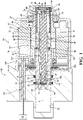
- a pressure supply unit 10 is generally shown for a brake system of an automobile. More particularly, as best shown in FIGS. 1 and 2 , the subject pressure supply unit 10 is used in conjunction with an electro-hydraulic brake-by-wire system where a motor 12, spindle 14, and piston 16 provide brake pressure in place of a traditional booster, master cylinder and brake pedal arrangement.
- the pressure supply unit 10 is commanded by an Electronic Control Unit (ECU) 18 (schematically shown) with derived signals from a traveler and/or forced sensor in a pedal feel emulator and/or from an auto pilot which can initiate braking independent of a driver.
- ECU Electronic Control Unit
- the pedal fee emulator provides brake pedal feel and feedback to a driver while a manual backup system is isolated from wheel brake circuits.
- the pressure supply unit 10 includes a booster body 20 that defines a cylinder 22 that extends along an axis.
- a motor cover 24 axially engages the booster body 20 and defines a compartment 26.
- the piston 16 is axially received by the cylinder 22 and axially slideable within the cylinder 22 and the compartment 26 of the motor cover 24 for creating a brake pressure in the cylinder 22 in response to the sliding movement of the piston 16.
- the piston 16 defines a bore 28 along the axis A, with the bore 28 terminating axially at an end 30.
- the booster body 20 further includes a pair of recesses 32 that extend radially outwardly into the booster body 20 from the cylinder 22, and extend annularly about the axis A. Each of the recesses 32 receives one of a pair of seals 34 that are configured to prevent the passage of fluid between the booster body 20 and piston 16 in the cylinder 22.
- the spindle 14 extends axially between a front end 36 received in the bore 28 of the piston 16, and a rear end 38 located axially outside of the bore 28 in the compartment 26 of the motor cover 24.
- the spindle 14 presents a threaded outer surface 40.
- a ball and socket joint 42 (discussed in further detail below) connects the spindle 14 to the piston 16 in the bore 28.
- the motor 12 is positioned about the spindle 14 in the compartment 26 of the motor cover 24.
- the motor 12 is configured to axially translate the spindle 14 for providing the axial movement of the piston 16.
- the motor 12 includes an annular stator 44 and an annular rotor 46, each positioned about the axis A.
- the annular rotor 46 has a magnetic outer surface and is rotatable within the stator 44 about the axis A in response to a current being applied to the stator 44.
- One or more bearings 48 are positioned radially between the rotor 46 and the motor cover 24 for accommodating rotation of the rotor 46 relative to the booster body 20.
- the motor 12 is connected to the ECU 18 to provide desired actuation of the motor 12.
- the rotor 46 presents an inner wall 50 that defines a channel 52 along the axis A.
- the channel 52 partially receives the piston 16 and receives the spindle 14.
- the inner wall 50 of the rotor 46 further defines a plurality of grooves 54 that extend axially and are arranged in circumferentially spaced relationship with one another.
- a nut 56 is fixed to the inner wall 50 of the rotor 46 and is configured to convert rotational movement of the rotor 46 into axial translation of the spindle 14. More particularly, the nut 56 presents a threaded inner surface 58 that is threadedly connected to the threaded outer surface 40 of the spindle 14 for providing axial movement of the spindle 14 in response to rotation of the rotor 46 and nut 56.
- the threaded connection between the nut 56 and spindle 14 may include a plurality of ball bearings 59 for facilitating rotation between the components.
- a conventional threaded connection comprised exclusively inner threads and outer threads may also be employed.
- the nut 56 extends axially between a first nut end 60 and a second nut end 62.
- a retainer plate 64 is fixed axially against the first nut end 60.
- a plurality of fasteners 66 such as bolts or the like, axially and rotationally fix the retainer plate 64 to the first nut end 60.
- the retainer plate 64 presents a plurality of guides 68 that extend radially outwardly from an outer circumference of the retainer plate 64.
- Each of the guides 68 are received by one of the grooves 54 of the rotor 46 to permit axially movement of the retainer plate 64 and nut 56 relative to the rotor 46 during assembly while inhibiting rotational movement of the retainer plate 64 and nut 56 relative to the rotor 46.
- an anti-rotation sleeve 70 is disposed about the spindle 14 and fixed to the booster body 20.
- the anti-rotation sleeve 70 is configured to inhibit rotation of the spindle 14 while permitting axial movement of the spindle 14.
- the anti-rotation sleeve 70 extends axially between a proximal end 72 axially engaging the motor cover 24 and a distal end 74 axially engaging the second nut end 62 of the nut 56.
- the anti-rotation sleeve 70 defines a radially inside wall 76.
- the inside wall 76 of the anti-rotation sleeve 70 defines a plurality of grooves 78 that extend axially and spaced circumferentially from one another.
- a retainer 80 is located about the axis A inside the anti-rotation sleeve 70 and keyed to the rear end 38 of the spindle 14.
- a generally rectangular-shaped protrusion 82 extends axially at the rear end 38 of the spindle 14.
- the retainer 80 defines an opening 84 that has substantially the same shape as the protrusion 82, and receives the protrusion 82 to key the retainer 80 to the spindle 14.
- the retainer 80 presents a plurality of fingers 86 that extend radially outwardly from an outer circumference of the retainer 80, with each finger 86 each received by one of the grooves 78 of the inside wall 76 of the anti-rotation sleeve 70 to inhibit rotational movement of the retainer 80 and spindle 14 while permitting axial movement of the retainer 80 and spindle 14 relative to the anti-rotation sleeve 70.
- a bolt 88 or the like is threadedly received by the protrusion 82 along the axis A and axially secures the retainer 80 to the spindle 14.
- one or more wave washers 89 or other spring elements are positioned axially between the retainer 80 and the motor cover 24 for accommodating axial movement of the spindle 14 toward the motor cover 24.
- the motor cover 24 presents an axially extending annular protrusion 90 that defines a pocket 92 inside the compartment 26 of the motor cover 24.
- the anti-rotation sleeve 70 is rotationally fixed to the motor cover 24 inside the pocket 92. More particularly, the anti-rotation sleeve 70 presents a flange 96 that extends radially outwardly at its proximal end 72.
- the flange 86 presents at least one first planar surface 98 along a radially outer surface of the flange 86.
- first planar surfaces 98 are located on circumferentially opposite sides of the anti-rotation sleeve 70, however any number of first planar surfaces 98 could be employed.
- an outer surface of the protrusion 90 is compressed / punched radially inwardly in circumferential alignment with each of the first planar surfaces 98 of the anti-rotation sleeve 70 to define one or more staked portions 99 for axially and rotationally fixing the anti-rotation sleeve 70 to the motor cover 24.
- the staked portions 99 may include one or more second planar surfaces 101 that overly the planar surfaces 98 to further aid in preventing rotation of the anti-rotation sleeve 70 relative to the motor cover 24.
- the ball and socket joint 42 includes a ball 102 at the front end 36 of the spindle 14, and a socket 104 adjacent to the end 30 of the bore 28 of the piston 16.
- the socket 104 receives the ball 102 to accommodate pivoting movement of the spindle 14 relative to the piston 16.
- the ball and socket joint 42 includes an insert 106 received in the bore 28 of the piston 16 and fixed to the piston 16 adjacent to the end 30 of the bore 28. The insert 106 defines the socket 104.
- the ball 102 defines at least one scored segment 108 for providing lateral movement of the ball 102 relative to the socket 104 while the ball 102 still inhibits pulling the spindle 14 axially free from the socket 104.
- the ball 102 defines a plurality of the scored segments 108 in spaced relationship with one another. Four scored segments 108 may be equally circumferentially spaced around the ball 102 to provide lateral movement in vertical and horizontal directions. Because of the scored segments 108, the ball and socket joint 42 helps to compensate for any angular misalignment between the piston 16 and spindle 14 to minimize premature wear out of the ball screw by minimizing side loads.
- the arrangement of the ball and socket joint 42 and piston 16 also eliminates the need for a separate sleeve with an anti-rotation feature, thus significantly reducing cost and assembly complexity. Furthermore, with careful sizing and/or shaping of the ball 102, small clearances can be maintained after insertion. This allows additional degrees of lateral freedom to assure elimination of binding of the spindle 14 at the ball 102. Since the ball 102 is primarily unilaterally loaded by system brake pressure, small amount of travel at the start position of the ball 102 can be easily compensated for.
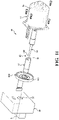
- FIGS. 9-10 due to the aforementioned arrangement of the piston 16 and ball and socket joint 42, two different assembly operations may be employed for installing the piston 16 and ball and socket joint 42. More particularly, according to a first operation illustrated in FIG. 9 , the piston 16 may first be installed in the booster body 20, and the ball and socket joint 42 may be snapped together after installation of the piston 16. Alternatively, as illustrated in FIG. 10 , the ball and socket joint 42 and piston 16 may be assembled in advance, and the piston 16 may subsequently be inserted into the cylinder 22 of the booster body 20. FIG. 11 shows an exploded assembly view of both of these arrangements.
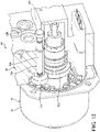
- a capacitive rotor angle sensor assembly 116 may be positioned about the rotor 46 and located axially between the stator 44 and the booster body 20.
- the capacitive rotor angle sensor assembly 116 includes a motor support plate 110 positioned axially against the booster body 20 in the compartment 26 of the motor cover 24 and positioned about the piston 16.
- At least one sensor bearing 114 is located between the motor support plate 110 and the rotor 46 in order to allow relative rotation between the motor support plate 110 and rotor 46.
- the capacitive rotor angle sensor assembly 116 includes a plurality of electrical connectors 118 electrically connecting the capacitive rotor angle sensor assembly 116 to the ECU 18 for transmitting rotor angle data 110.
- a first gear 122 is rotatable with the rotor 46.
- a second gear 124 is meshed with the first gear 122.
- An axially extending rod 126 is rotatable with the second gear 124 and is connected to a magnet 128.
- a magnet sensor 130 is configured to detect the magnet 128 for determining rotor angle data and transmitting the rotor angle data to the ECU 18.
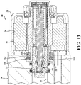
- FIG. 13 illustrates that according to this arrangement, the first gear 122 may have a smaller diameter than the sensor bearing 114.
- the sensor bearing 114 can be designed with the motor cover 24 as a "half-in / half-out" design and be used to pilot the motor 12 into the booster body 20.
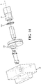
- FIG. 14 illustrates a connection of a first gear 122 to a rotor 46 according to this embodiment.
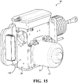
- FIGS. 15-20 a design advantage of the subject pressure supply unit 10 is that the motor 12 and piston 16 require no external feature in the cylinder 22 to restrain rotation of the piston 16. Accordingly, even though the overall length of the motor 12 may be relatively long, savings in length of the cylinder 22 can compensate for this.
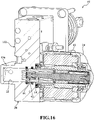
- FIGS. 15-16 show a first design in which a single master cylinder HCU block (anti-lock brake system controller) 132 has an extruded, transverse boss 136 which defines the cylinder 22. The boss is integrally formed with the booster body 20.
- FIGS. 15-16 show a first design in which a single master cylinder HCU block (anti-lock brake system controller) 132 has an extruded, transverse boss 136 which defines the cylinder 22. The boss is integrally formed with the booster body 20.
- FIGS. 19-20 show a design in which a machined or cast and machined master cylinder block 134 is incorporated with a parallel motor 12 layout.
Landscapes
- Engineering & Computer Science (AREA)
- Transportation (AREA)
- Mechanical Engineering (AREA)
- Physics & Mathematics (AREA)
- Fluid Mechanics (AREA)
- Braking Systems And Boosters (AREA)
- Transmission Of Braking Force In Braking Systems (AREA)
- Pivots And Pivotal Connections (AREA)
- Braking Arrangements (AREA)
Abstract
Description
- A pressure supply unit for a brake system of a vehicle such as an automobile.
- Pressure supply units are used in conjunction with electro-hydraulic brake-by-wire systems for vehicles such as automobiles to provide brake pressure in place of a traditional booster, master cylinder and brake pedal arrangement. Pressure supply units are commanded by an Electronic Control Unit (ECU) which derives signals from a driver via sensors in a pedal feel emulator and/or from an auto pilot that can self-apply the brakes without driver intervention. Pressure supply units typically include a motor comprised of a stator and a rotatable rotor container within the stator, with the rotor housing a high efficiency screw assembly which is furthermore attached to a piston contained in a cylinder of a booster body. Rotation of the rotor effectuates translating movement of the spindle and piston, thereby causing the brake pressure change for effectuating the brakes.
- There remains a continued need for improvements to such pressure supply units.
- According to an aspect of the disclosure, a pressure supply unit is provided for a brake system. The pressure supply unit comprises a booster body that defines a cylinder that extends along an axis. A piston is axially slideable within the cylinder. The piston defines a bore along the axis. A spindle extends along the axis and is received by the bore of the piston. The spindle is rotationally fixed and axially moveable for providing the axial movement of the piston. A motor is positioned about the spindle and is configured to axially translate the spindle for providing the axial movement of the piston. A ball and socket joint couples the piston and spindle while accommodating pivoting movement of the spindle relative to the piston. The ball and socket joint comprises a ball at a front end of the spindle and a socket in the bore of the piston which receives the ball.
- The ball and socket joint provides a simple manner of accommodate pivoting movement of the spindle relative to the piston, thus providing reduced wear of the spindle and piston.
- According to another aspect of the disclosure, a pressure supply unit is provided for a brake system. The pressure supply unit comprises a booster body that defines a cylinder extending along an axis. A piston is axially slideable within the cylinder. The piston defines a bore along the axis. A spindle extends along the axis and is received by the bore of the piston. The spindle is rotationally fixed and axially moveable for providing the axial movement of the piston. A motor is positioned about the spindle and configured to axially translate the spindle for providing the axial movement of the piston. The motor comprises an annular stator and an annular rotor rotatable within the stator in response to a current passing into the stator. At least one gear is rotatable in response to rotation of the rotor and is configured to rotate a magnet. A sensor is provided for detecting rotation of the magnet to determine a rotor angle of the rotor.
- The arrangement of the at least one gear and sensor provide a simple, compact and reliable method for detecting a rotor angle of the rotor.
- According to another aspect of the disclosure, a pressure supply unit is provided for a brake system. The pressure supply unit comprises a booster body that defines a cylinder extending along an axis. A motor cover is coupled to the booster body and defines a compartment. A piston is axially slideable within the cylinder. The piston defines a bore along the axis. A spindle extends along the axis and is received by the bore of the piston. The spindle is rotationally fixed and axially moveable for providing the axial movement of the piston. A motor is positioned about the spindle in the compartment of the motor cover and configured to axially translate the spindle for providing the axial movement of the piston. The motor comprises an annular stator and an annular rotor rotatable within the stator in response to a current passing into the stator. An anti-rotation sleeve is disposed about the spindle and fixed to the motor cover. The anti-rotation sleeve is configured to inhibit rotation of the spindle while permitting axial movement of the spindle. The motor cover presents an axially extending annular protrusion defining a pocket inside the compartment inside the motor cover. The anti-rotation sleeve is fixed to the motor cover inside the pocket.
- The arrangement of the anti-rotation sleeve is fixed to the pocket of the motor cover provides a compact and simple arrangement for preventing rotation of the spindle. This arrangement further allows the motor cover to be constructed without a separate end cap on the motor housing.
- Other advantages of the present invention will be readily appreciated, as the same becomes better understood by reference to the following detailed description when considered in connection with the accompanying drawings wherein:
-
FIG. 1 is a cross-sectional side view of an example embodiment of a pressure supply unit; -
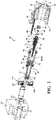
FIG. 2 is an exploded, perspective view of pressure supply unit; -
FIG. 3 is a cutaway, perspective view of a rotor and nut of the pressure supply unit; -
FIG. 4 is an exploded, cutaway, perspective view of an anti-rotation sleeve of the pressure supply unit, illustrating its connection to a spindle; -
FIG. 5 is a perspective view of the anti-rotation sleeve, illustrating a planar surface for fixing the anti-rotation sleeve to a motor cover; -
FIG. 6 is a perspective view of a protrusion of a motor cover, illustrating the protrusion receiving and fixed to the anti-rotation sleeve; -
FIG. 6A is a front cross-sectional view of a pair of staked portions of the motor cover engaging planar surfaces of the anti-rotation sleeve; -
FIG. 7 is a perspective view of a ball of a ball and socket joint located at the end of the spindle, illustrating a plurality of scored segments on the ball; -
FIG. 8 is a magnified, cutaway view of the ball and socket joint, illustrating the scored segments relative to the socket; -
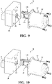
FIG. 9 is a perspective view of the pressure supply unit, illustrating an arrangement in which the piston is installed in the booster body prior to being connected to the spindle with the ball and socket joint; -
FIG. 10 is a perspective view of the pressure supply unit, illustrating an arrangement in which the piston and spindle are pre-assembled with the ball and socket joint prior to being connected to the booster body; -
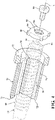
FIG. 11 is a perspective exploded view of the arrangements ofFIGS. 9-10 ; -
FIG. 12 is a perspective cutaway view of the pressure supply unit, illustrating an alternate arrangement of a rotor angle sensor assembly; -
FIG. 13 is a side cutaway view of the pressure supply unit, illustrating the alternate arrangement of the rotor angle sensor assembly; -
FIG. 14 is a perspective exploded view of the pressure supply unit, illustrating a gear of the alternate arrangement of the rotor angle sensor assembly; -
FIG. 15 is a perspective view of an arrangement of the pressure supply unit in which a single master cylinder hydraulic control unit block has an extruded, transverse boss which defines the cylinder; -
FIG. 16 is a cutaway view ofFIG. 15 ; -
FIG. 17 is a perspective view of an arrangement of the pressure supply unit including a simplified sleeve which defines the cylinder; -
FIG. 18 is a cutaway view ofFIG. 17 ; -
FIG. 19 is a perspective view of an arrangement of the pressure supply unit in which master cylinder block is incorporated with a parallel motor layout; and -
FIG. 20 is a cutaway view ofFIG. 19 . - Referring to the figures, wherein like numerals indicate corresponding parts throughout the several views, a
pressure supply unit 10 is generally shown for a brake system of an automobile. More particularly, as best shown inFIGS. 1 and2 , the subjectpressure supply unit 10 is used in conjunction with an electro-hydraulic brake-by-wire system where amotor 12,spindle 14, andpiston 16 provide brake pressure in place of a traditional booster, master cylinder and brake pedal arrangement. Thepressure supply unit 10 is commanded by an Electronic Control Unit (ECU) 18 (schematically shown) with derived signals from a traveler and/or forced sensor in a pedal feel emulator and/or from an auto pilot which can initiate braking independent of a driver. The pedal fee emulator provides brake pedal feel and feedback to a driver while a manual backup system is isolated from wheel brake circuits. - In more detail, the
pressure supply unit 10 includes abooster body 20 that defines acylinder 22 that extends along an axis. Amotor cover 24 axially engages thebooster body 20 and defines acompartment 26. Thepiston 16 is axially received by thecylinder 22 and axially slideable within thecylinder 22 and thecompartment 26 of themotor cover 24 for creating a brake pressure in thecylinder 22 in response to the sliding movement of thepiston 16. Thepiston 16 defines abore 28 along the axis A, with thebore 28 terminating axially at anend 30. Thebooster body 20 further includes a pair ofrecesses 32 that extend radially outwardly into thebooster body 20 from thecylinder 22, and extend annularly about the axis A. Each of therecesses 32 receives one of a pair ofseals 34 that are configured to prevent the passage of fluid between thebooster body 20 andpiston 16 in thecylinder 22. - The
spindle 14 extends axially between afront end 36 received in thebore 28 of thepiston 16, and arear end 38 located axially outside of thebore 28 in thecompartment 26 of themotor cover 24. Thespindle 14 presents a threadedouter surface 40. A ball and socket joint 42 (discussed in further detail below) connects thespindle 14 to thepiston 16 in thebore 28. - The
motor 12 is positioned about thespindle 14 in thecompartment 26 of themotor cover 24. Themotor 12 is configured to axially translate thespindle 14 for providing the axial movement of thepiston 16. More particularly, themotor 12 includes anannular stator 44 and anannular rotor 46, each positioned about the axis A. Theannular rotor 46 has a magnetic outer surface and is rotatable within thestator 44 about the axis A in response to a current being applied to thestator 44. One ormore bearings 48 are positioned radially between therotor 46 and themotor cover 24 for accommodating rotation of therotor 46 relative to thebooster body 20. As schematically shown, themotor 12 is connected to theECU 18 to provide desired actuation of themotor 12. - The
rotor 46 presents an inner wall 50 that defines a channel 52 along the axis A. The channel 52 partially receives thepiston 16 and receives thespindle 14. As best shown inFIG. 3 , the inner wall 50 of therotor 46 further defines a plurality ofgrooves 54 that extend axially and are arranged in circumferentially spaced relationship with one another. - A
nut 56 is fixed to the inner wall 50 of therotor 46 and is configured to convert rotational movement of therotor 46 into axial translation of thespindle 14. More particularly, thenut 56 presents a threadedinner surface 58 that is threadedly connected to the threadedouter surface 40 of thespindle 14 for providing axial movement of thespindle 14 in response to rotation of therotor 46 andnut 56. The threaded connection between thenut 56 andspindle 14 may include a plurality ofball bearings 59 for facilitating rotation between the components. A conventional threaded connection comprised exclusively inner threads and outer threads may also be employed. Thenut 56 extends axially between afirst nut end 60 and asecond nut end 62. Aretainer plate 64 is fixed axially against thefirst nut end 60. A plurality offasteners 66, such as bolts or the like, axially and rotationally fix theretainer plate 64 to thefirst nut end 60. Theretainer plate 64 presents a plurality ofguides 68 that extend radially outwardly from an outer circumference of theretainer plate 64. Each of theguides 68 are received by one of thegrooves 54 of therotor 46 to permit axially movement of theretainer plate 64 andnut 56 relative to therotor 46 during assembly while inhibiting rotational movement of theretainer plate 64 andnut 56 relative to therotor 46. - As best shown in
FIG. 4 , ananti-rotation sleeve 70 is disposed about thespindle 14 and fixed to thebooster body 20. Theanti-rotation sleeve 70 is configured to inhibit rotation of thespindle 14 while permitting axial movement of thespindle 14. Theanti-rotation sleeve 70 extends axially between aproximal end 72 axially engaging themotor cover 24 and adistal end 74 axially engaging thesecond nut end 62 of thenut 56. Theanti-rotation sleeve 70 defines a radially insidewall 76. Theinside wall 76 of theanti-rotation sleeve 70 defines a plurality ofgrooves 78 that extend axially and spaced circumferentially from one another. Aretainer 80 is located about the axis A inside theanti-rotation sleeve 70 and keyed to therear end 38 of thespindle 14. A generally rectangular-shapedprotrusion 82 extends axially at therear end 38 of thespindle 14. Theretainer 80 defines anopening 84 that has substantially the same shape as theprotrusion 82, and receives theprotrusion 82 to key theretainer 80 to thespindle 14. Theretainer 80 presents a plurality offingers 86 that extend radially outwardly from an outer circumference of theretainer 80, with eachfinger 86 each received by one of thegrooves 78 of theinside wall 76 of theanti-rotation sleeve 70 to inhibit rotational movement of theretainer 80 andspindle 14 while permitting axial movement of theretainer 80 andspindle 14 relative to theanti-rotation sleeve 70. Abolt 88 or the like is threadedly received by theprotrusion 82 along the axis A and axially secures theretainer 80 to thespindle 14. As best shown inFIGS. 1 and2 , one ormore wave washers 89 or other spring elements are positioned axially between theretainer 80 and themotor cover 24 for accommodating axial movement of thespindle 14 toward themotor cover 24. - As best shown in
FIGS. 1 and5-6A , themotor cover 24 presents an axially extendingannular protrusion 90 that defines apocket 92 inside thecompartment 26 of themotor cover 24. Theanti-rotation sleeve 70 is rotationally fixed to themotor cover 24 inside thepocket 92. More particularly, theanti-rotation sleeve 70 presents aflange 96 that extends radially outwardly at itsproximal end 72. Theflange 86 presents at least one firstplanar surface 98 along a radially outer surface of theflange 86. According to the example embodiment, a pair of firstplanar surfaces 98 are located on circumferentially opposite sides of theanti-rotation sleeve 70, however any number of firstplanar surfaces 98 could be employed. As best shown inFIG. 6A , an outer surface of theprotrusion 90 is compressed / punched radially inwardly in circumferential alignment with each of the firstplanar surfaces 98 of theanti-rotation sleeve 70 to define one or more stakedportions 99 for axially and rotationally fixing theanti-rotation sleeve 70 to themotor cover 24. The stakedportions 99 may include one or more secondplanar surfaces 101 that overly theplanar surfaces 98 to further aid in preventing rotation of theanti-rotation sleeve 70 relative to themotor cover 24. - As best shown in
FIGS. 1 and7-8 . the ball and socket joint 42 includes aball 102 at thefront end 36 of thespindle 14, and asocket 104 adjacent to theend 30 of thebore 28 of thepiston 16. Thesocket 104 receives theball 102 to accommodate pivoting movement of thespindle 14 relative to thepiston 16. The ball and socket joint 42 includes an insert 106 received in thebore 28 of thepiston 16 and fixed to thepiston 16 adjacent to theend 30 of thebore 28. The insert 106 defines thesocket 104. - As best shown in
FIGS. 7-8 , theball 102 defines at least one scoredsegment 108 for providing lateral movement of theball 102 relative to thesocket 104 while theball 102 still inhibits pulling thespindle 14 axially free from thesocket 104. According to the example embodiment, theball 102 defines a plurality of the scoredsegments 108 in spaced relationship with one another. Four scoredsegments 108 may be equally circumferentially spaced around theball 102 to provide lateral movement in vertical and horizontal directions. Because of the scoredsegments 108, the ball and socket joint 42 helps to compensate for any angular misalignment between thepiston 16 andspindle 14 to minimize premature wear out of the ball screw by minimizing side loads. The arrangement of the ball and socket joint 42 andpiston 16 also eliminates the need for a separate sleeve with an anti-rotation feature, thus significantly reducing cost and assembly complexity. Furthermore, with careful sizing and/or shaping of theball 102, small clearances can be maintained after insertion. This allows additional degrees of lateral freedom to assure elimination of binding of thespindle 14 at theball 102. Since theball 102 is primarily unilaterally loaded by system brake pressure, small amount of travel at the start position of theball 102 can be easily compensated for. - It should be appreciated that due to the locations and arrangements of the
anti-rotation sleeve 70 and ball and socket joint 42, side loads betweenpiston 16 andspindle 14 are virtually non-existent. - As set forth in
FIGS. 9-10 , due to the aforementioned arrangement of thepiston 16 and ball and socket joint 42, two different assembly operations may be employed for installing thepiston 16 and ball andsocket joint 42. More particularly, according to a first operation illustrated inFIG. 9 , thepiston 16 may first be installed in thebooster body 20, and the ball and socket joint 42 may be snapped together after installation of thepiston 16. Alternatively, as illustrated inFIG. 10 , the ball and socket joint 42 andpiston 16 may be assembled in advance, and thepiston 16 may subsequently be inserted into thecylinder 22 of thebooster body 20.FIG. 11 shows an exploded assembly view of both of these arrangements. - As best shown in
FIGS. 1-2 , a capacitive rotorangle sensor assembly 116 may be positioned about therotor 46 and located axially between thestator 44 and thebooster body 20. The capacitive rotorangle sensor assembly 116 includes amotor support plate 110 positioned axially against thebooster body 20 in thecompartment 26 of themotor cover 24 and positioned about thepiston 16. At least onesensor bearing 114 is located between themotor support plate 110 and therotor 46 in order to allow relative rotation between themotor support plate 110 androtor 46. The capacitive rotorangle sensor assembly 116 includes a plurality ofelectrical connectors 118 electrically connecting the capacitive rotorangle sensor assembly 116 to theECU 18 for transmittingrotor angle data 110. - According to an alternate embodiment of a rotor
angle sensor assembly 120 best presented inFIG. 12 , afirst gear 122 is rotatable with therotor 46. Asecond gear 124 is meshed with thefirst gear 122. An axially extendingrod 126 is rotatable with thesecond gear 124 and is connected to amagnet 128. Amagnet sensor 130 is configured to detect themagnet 128 for determining rotor angle data and transmitting the rotor angle data to theECU 18.FIG. 13 illustrates that according to this arrangement, thefirst gear 122 may have a smaller diameter than thesensor bearing 114. Accordingly, thesensor bearing 114 can be designed with themotor cover 24 as a "half-in / half-out" design and be used to pilot themotor 12 into thebooster body 20.FIG. 14 illustrates a connection of afirst gear 122 to arotor 46 according to this embodiment. - As demonstrated by
FIGS. 15-20 , a design advantage of the subjectpressure supply unit 10 is that themotor 12 andpiston 16 require no external feature in thecylinder 22 to restrain rotation of thepiston 16. Accordingly, even though the overall length of themotor 12 may be relatively long, savings in length of thecylinder 22 can compensate for this. To this point, three different embodiments for packaging the system are shown inFIGS. 15-20 . More particularly,FIGS. 15-16 show a first design in which a single master cylinder HCU block (anti-lock brake system controller) 132 has an extruded,transverse boss 136 which defines thecylinder 22. The boss is integrally formed with thebooster body 20. Furthermore,FIGS. 17-18 show asimplified sleeve 138 which defines the cylinder 22 (no rotational constraints necessary) that is coupled with abooster body 20 in which an extruded rectangular master cylinder /HCU block 132 is designed with atransverse motor 12. Furthermore,FIGS. 19-20 show a design in which a machined or cast and machinedmaster cylinder block 134 is incorporated with aparallel motor 12 layout. - It should be appreciated that the simple assembly of the overall design of the subject
pressure supply unit 10 provides cost savings advantages, elimination of critical build tolerance, and assembly processes geared to high volume production. - Obviously, many modifications and variations of the present invention are possible in light of the above teachings and may be practiced otherwise than as specifically described while within the scope of the appended claims. Notably, features of the embodiments described herein may be used in conjunction with one another in various combinations.
Claims (15)
- A pressure supply unit (10) for a brake system, comprising:a booster body (20) defining a cylinder (22) extending along an axis (A);a piston (16) axially slideable within the cylinder (22);the piston (16) defining a bore (28) along the axis (A);a spindle (14) extending along the axis (A) and received by the bore (28) of the piston (16) and rotationally fixed and axially moveable for providing the axial movement of the piston (16);a motor positioned about the spindle (14) and configured to axially translate the spindle (14) for providing the axial movement of the piston (16); anda ball and socket joint (42) coupling the spindle (14) to the piston (16), the ball and socket joint (42) comprising a ball (102) at a front end of the spindle (14) and a socket (104) in the bore (28) of the piston (16) and receiving the ball (102) to accommodate pivoting movement of the spindle (14) relative to the piston (16).
- The pressure supply unit as set forth in Claim 1, wherein the ball (102) defines at least one scored segment (108) for providing lateral movement of the ball (102) relative to the socket (104) while allowing the ball (102) to inhibit axial movement of the ball (102) outside of the socket (104), particularly wherein the ball (102) defines a plurality of scored segments (108) in spaced relationship with one another.
- The pressure supply unit as set forth in claim 1 or 2, wherein the bore (28) of the piston (16) terminates at an end, and wherein the socket (104) is located adjacent to the end of the bore (28).
- The pressure supply unit as set forth in claim 3, wherein an insert (106) is received in the bore (28) or the piston (16) and fixed to the piston (16) adjacent to the end of the bore (28), and wherein the insert (106) defines the socket (104).
- The pressure supply unit as set forth in any one of Claims 1 to 4 further comprising a nut (56) fixed to the inner wall (50) of the rotor (46), the nut (56) presenting a threaded inner surface (58) threadedly connected to a threaded outer surface (40) of the spindle (14) for providing the axial movement of the spindle (14) in response to rotation of the rotor (46) and the nut (56).
- The pressure supply unit as set forth in claim 5, wherein the rotor (46) presents an inner wall (50) defining a plurality of grooves (54) extending axially and circumferentially spaced from one another, wherein a retainer plate (64) is fixed axially against an end of the nut (56), and wherein the retainer plate (64) presents a plurality of guides (68) extending radially outwardly from an outer circumference of the retainer plate (64) and each received by one of the grooves (54) of the rotor (46) to permit axially movement of the retainer plate (64) and nut (56) relative to the rotor (46) during assembly while inhibiting rotational movement of the retainer plate (64) and nut (56) relative to the rotor (46).
- The pressure supply unit as set forth in claim 6, wherein a plurality of fasteners (66) axially and rotationally fix the retainer plate (64) to the first nut end (60).
- The pressure supply unit as set forth in any one of claims 1 to 7 further comprising an anti-rotation sleeve (70) disposed about the spindle (14) and fixed to the motor cover (24) and configured to inhibit rotation of the spindle (14) while permitting axial movement of the spindle (14).
- The pressure supply unit as set forth in claim 8, wherein a motor cover (24) is coupled to the booster body (20) and defines a compartment (26), wherein the motor and anti-rotation sleeve (70) are located in the compartment (26), and wherein the motor cover (24) presents an axially extending annular protrusion (90) defining a pocket (92) inside the compartment (26) inside the motor cover (24), and wherein the anti-rotation sleeve (70) is rotationally fixed to the motor cover (24) inside the pocket (92).
- The pressure supply unit as set forth in claim 9, wherein the anti-rotation sleeve (70) presents at least one planar surface (98) along a radially outer surface of the anti-rotation sleeve (70), and wherein the motor cover (24) defines a staked portion (99) radially engaging the at least one planar surface (98) to rotationally fix the anti-rotation sleeve (70) relative to the motor cover (24).
- The pressure supply unit as set forth in any one of claims 1 to 10, wherein at least one gear (122, 124) is rotatable with the rotor (46) and configured to rotate a magnet (128), and wherein a sensor detects rotation of the magnet (128) to determine a rotor angle, particularly wherein the at least one gear (122, 124) comprises a first gear (122) connected to the rotor (46), and a second gear (124) meshed with the first gear (122), and wherein a rod (126) is connected with the second gear (124), and wherein the magnet (128) is coupled with an end of the rod (126) located opposite the second gear (124).
- The pressure supply unit as set forth in any one of claims 1 to 11, wherein the motor (12) comprises: an annular stator (44) and an annular rotor (46) rotatable within the stator (44) in response to a current passing into the stator (44); and wherein the pressure supply unit (10) further comprises at least one gear (122, 124) rotatable in response to rotation of the rotor (46) and configured to rotate a magnet (128), and a sensor for detecting rotation of the magnet (128) to determine a rotor angle of the rotor (46).
- The pressure supply unit as set forth in claim 12, wherein the at least one gear comprises (122, 124) a first gear (122) positioned about and rotatable with the rotor (46), and a second gear (124) meshed with the first gear (122) and configured to rotate the magnet (128),
particularly wherein a rod (126) is connected with the second gear (124), and wherein the magnet (128) is coupled with an end of the rod (126) located opposite the second gear (124). - The pressure supply unit as set forth in any one of claims 1 to 13, further comprising: a motor cover (24) coupled to the booster body (20) and defining a compartment (26),wherein the motor (12) is positioned about the spindle (14) in the compartment (26) of the motor cover (24);the motor (12) comprises an annular stator (44) and an annular rotor (46) rotatable within the stator (44) in response to a current passing into the stator (44);wherein the pressure supply unit (10) further comprises an anti-rotation sleeve (70) disposed about the spindle (14) and fixed to the motor cover (24) and inhibiting rotation of the spindle (14) while permitting axial movement of the spindle (14); andthe motor cover (24) presents an axially extending annular protrusion (90) defining a pocket (92) inside the compartment (26) inside the motor cover (24), and the anti-rotation sleeve (70) is rotationally fixed to the motor cover (24) inside the pocket (92).
- The pressure supply unit as set forth in claim 14, wherein the anti-rotation sleeve (70) presents at least one planar surface (98) along a radially outer surface of the anti-rotation sleeve (70), and wherein the motor cover (24) defines at least one staked portion (99) engaging the at least one planar surface (98) for rotationally fixing the anti-rotation sleeve (70) to the motor cover (24),particularly wherein the at least one planar surface (98) of the anti-rotation sleeve (70) is a pair of planar surfaces (98) positioned on circumferentially opposite sides of the pocket (92), and wherein the at least one staked portion (99) comprises a pair of staked portions (99) each engaging one of the planar surfaces (98), and/orparticularly wherein the at least one staked portion (99) of the motor cover (24) defines an inner planar surface aligned with the at least one planar surface of the anti-rotation sleeve (70) for further preventing rotation of the anti-rotation sleeve (70) relative to the motor cover (24).
Applications Claiming Priority (2)
| Application Number | Priority Date | Filing Date | Title |
|---|---|---|---|
| US17/346,240 US11613239B2 (en) | 2021-06-12 | 2021-06-12 | Pressure supply unit for a brake system of a vehicle |
| CN202210634158.9A CN114954406B (en) | 2021-06-12 | 2022-06-07 | Pressure supply unit for a brake system |
Publications (2)
| Publication Number | Publication Date |
|---|---|
| EP4101707A2 true EP4101707A2 (en) | 2022-12-14 |
| EP4101707A3 EP4101707A3 (en) | 2022-12-21 |
Family
ID=82020255
Family Applications (1)
| Application Number | Title | Priority Date | Filing Date |
|---|---|---|---|
| EP22178362.4A Pending EP4101707A3 (en) | 2021-06-12 | 2022-06-10 | Pressure supply unit for a brake system of a vehicle |
Country Status (3)
| Country | Link |
|---|---|
| EP (1) | EP4101707A3 (en) |
| JP (1) | JP7431279B2 (en) |
| KR (1) | KR102663651B1 (en) |
Family Cites Families (14)
| Publication number | Priority date | Publication date | Assignee | Title |
|---|---|---|---|---|
| DE4426682A1 (en) * | 1994-07-28 | 1996-02-01 | Teves Gmbh Alfred | Electronically controllable brake actuation system |
| DE10049913A1 (en) * | 1999-10-18 | 2001-04-19 | Luk Lamellen & Kupplungsbau | Master cylinder for a clutch or brake mechanism of a motor vehicle comprises an axially dispaceable piston and its sealing means which are rotated relative to one another when the cylinder is operated |
| DE102008038320A1 (en) * | 2007-11-27 | 2009-05-28 | Continental Teves Ag & Co. Ohg | Brake actuation unit |
| US20100247232A1 (en) * | 2009-03-29 | 2010-09-30 | Hsiu-Nien Lin | Two-section tool joint |
| DE102013213888B3 (en) | 2013-07-16 | 2014-11-13 | Robert Bosch Gmbh | Electrohydraulic actuator |
| JP6344721B2 (en) | 2014-10-31 | 2018-06-20 | ヴィオニア日信ブレーキシステムジャパン株式会社 | Hydraulic pressure generator |
| DE102015104246A1 (en) * | 2015-03-20 | 2016-09-22 | Ipgate Ag | Actuating device for a motor vehicle brake |
| WO2016194582A1 (en) | 2015-05-29 | 2016-12-08 | 日立オートモティブシステムズ株式会社 | Electric booster |
| DE102016105232A1 (en) | 2016-03-21 | 2017-09-21 | Ipgate Ag | Actuating device for a hydraulic actuation system, in particular a motor vehicle brake or an electrified clutch and gear actuator |
| FR3051856B1 (en) | 2016-05-27 | 2018-05-25 | Valeo Embrayages | HYDRAULIC TRANSMITTER CYLINDER FOR A HYDRAULIC CONTROL DEVICE |
| DE102016014483A1 (en) | 2016-12-06 | 2018-06-07 | Lucas Automotive Gmbh | Master brake cylinder arrangement with position sensor element and coupling arrangement therefor |
| US10001163B1 (en) * | 2016-12-22 | 2018-06-19 | Federal-Mogul Motorparts, LLC | Ball joint with improved upper bearing and method of construction thereof |
| DE102017113725A1 (en) * | 2017-06-21 | 2018-12-27 | Schaeffler Technologies AG & Co. KG | Piston-cylinder arrangement |
| WO2019003944A1 (en) | 2017-06-27 | 2019-01-03 | 日立オートモティブシステムズ株式会社 | Electric booster device and booster device |
-
2022
- 2022-06-10 JP JP2022094561A patent/JP7431279B2/en active Active
- 2022-06-10 EP EP22178362.4A patent/EP4101707A3/en active Pending
- 2022-06-13 KR KR1020220071630A patent/KR102663651B1/en active IP Right Grant
Also Published As
| Publication number | Publication date |
|---|---|
| KR102663651B1 (en) | 2024-05-14 |
| KR20220167356A (en) | 2022-12-20 |
| EP4101707A3 (en) | 2022-12-21 |
| JP7431279B2 (en) | 2024-02-14 |
| JP2022189821A (en) | 2022-12-22 |
Similar Documents
| Publication | Publication Date | Title |
|---|---|---|
| US11613239B2 (en) | Pressure supply unit for a brake system of a vehicle | |
| US20240149848A1 (en) | Actuation device for a hydraulic actuation system, in particular a motor vehicle brake or an electrified clutch actuator, optionally with gear actuator | |
| US9151352B2 (en) | Device for vibration-damping mounting of a fluid assembly and associated fluid assembly | |
| CN109249920B (en) | Piston pump assembly for a hydraulic power-assisted vehicle brake system | |
| US7559410B2 (en) | Electronic drive of a parking brake | |
| EP1997702B1 (en) | Electrically driven brake booster | |
| US20170166177A1 (en) | Pressure generating apparatus for a braking system of a motor vehicle, hydraulic assemblage for interacting with the pressure generating apparatus, braking system, and method for installing a braking system for a motor vehicle | |
| CN103237700B (en) | Electric booster | |
| CN108216178B (en) | Hydraulic assembly of brake adjusting part of vehicle hydraulic brake equipment | |
| US8911029B2 (en) | Electric braking device | |
| DE102014214095A1 (en) | Actuator for an electro-hydraulic brake system | |
| US20190322264A1 (en) | Hydraulic block for a hydraulic unit of a brake control system and method for the manufacture thereof | |
| EP4101707A2 (en) | Pressure supply unit for a brake system of a vehicle | |
| CN106838129A (en) | With worm and gear, brake and steering that centre-to-centre spacing regulation and gap eliminate | |
| KR102608300B1 (en) | Oil pressure generator for brake system | |
| US12044278B2 (en) | Anti-rattle caliper sleeve | |
| CN113692370B (en) | Electromechanical brake pressure generator for a hydraulic brake system | |
| US20230391308A1 (en) | Actuation device for a brake system | |
| CN117261518B (en) | Electric control type active suspension system | |
| JP6407356B1 (en) | Rotating electric machine for vehicles | |
| WO2023057406A1 (en) | Electric motor of an ancillary unit of a motor vehicle | |
| CN115703449A (en) | Electromechanical brake booster | |
| CN115743075A (en) | Electromechanical brake booster and control method thereof | |
| CN115701396A (en) | Electromechanical brake booster | |
| CN117465537A (en) | Eccentric bearing rack anti-rotation assembly |
Legal Events
| Date | Code | Title | Description |
|---|---|---|---|
| STAA | Information on the status of an ep patent application or granted ep patent |
Free format text: STATUS: UNKNOWN |
|
| PUAI | Public reference made under article 153(3) epc to a published international application that has entered the european phase |
Free format text: ORIGINAL CODE: 0009012 |
|
| STAA | Information on the status of an ep patent application or granted ep patent |
Free format text: STATUS: THE APPLICATION HAS BEEN PUBLISHED |
|
| PUAL | Search report despatched |
Free format text: ORIGINAL CODE: 0009013 |
|
| AK | Designated contracting states |
Kind code of ref document: A2 Designated state(s): AL AT BE BG CH CY CZ DE DK EE ES FI FR GB GR HR HU IE IS IT LI LT LU LV MC MK MT NL NO PL PT RO RS SE SI SK SM TR |
|
| AK | Designated contracting states |
Kind code of ref document: A3 Designated state(s): AL AT BE BG CH CY CZ DE DK EE ES FI FR GB GR HR HU IE IS IT LI LT LU LV MC MK MT NL NO PL PT RO RS SE SI SK SM TR |
|
| RIC1 | Information provided on ipc code assigned before grant |
Ipc: B60T 13/74 20060101ALI20221111BHEP Ipc: B60T 13/66 20060101ALI20221111BHEP Ipc: B60T 13/16 20060101ALI20221111BHEP Ipc: B60T 13/14 20060101ALI20221111BHEP Ipc: B60T 8/40 20060101ALI20221111BHEP Ipc: B60T 8/34 20060101ALI20221111BHEP Ipc: B60T 8/171 20060101ALI20221111BHEP Ipc: B60T 7/04 20060101AFI20221111BHEP |
|
| STAA | Information on the status of an ep patent application or granted ep patent |
Free format text: STATUS: REQUEST FOR EXAMINATION WAS MADE |
|
| 17P | Request for examination filed |
Effective date: 20230621 |
|
| RBV | Designated contracting states (corrected) |
Designated state(s): AL AT BE BG CH CY CZ DE DK EE ES FI FR GB GR HR HU IE IS IT LI LT LU LV MC MK MT NL NO PL PT RO RS SE SI SK SM TR |
|
| GRAP | Despatch of communication of intention to grant a patent |
Free format text: ORIGINAL CODE: EPIDOSNIGR1 |
|
| STAA | Information on the status of an ep patent application or granted ep patent |
Free format text: STATUS: GRANT OF PATENT IS INTENDED |
|
| INTG | Intention to grant announced |
Effective date: 20240606 |