EP4101690A1 - Back pad assembly for a material handling vehicle - Google Patents
Back pad assembly for a material handling vehicle Download PDFInfo
- Publication number
- EP4101690A1 EP4101690A1 EP22178597.5A EP22178597A EP4101690A1 EP 4101690 A1 EP4101690 A1 EP 4101690A1 EP 22178597 A EP22178597 A EP 22178597A EP 4101690 A1 EP4101690 A1 EP 4101690A1
- Authority
- EP
- European Patent Office
- Prior art keywords
- back pad
- handle
- material handling
- handling vehicle
- framework
- Prior art date
- Legal status (The legal status is an assumption and is not a legal conclusion. Google has not performed a legal analysis and makes no representation as to the accuracy of the status listed.)
- Granted
Links
Images







Classifications
-
- B—PERFORMING OPERATIONS; TRANSPORTING
- B66—HOISTING; LIFTING; HAULING
- B66F—HOISTING, LIFTING, HAULING OR PUSHING, NOT OTHERWISE PROVIDED FOR, e.g. DEVICES WHICH APPLY A LIFTING OR PUSHING FORCE DIRECTLY TO THE SURFACE OF A LOAD
- B66F9/00—Devices for lifting or lowering bulky or heavy goods for loading or unloading purposes
- B66F9/06—Devices for lifting or lowering bulky or heavy goods for loading or unloading purposes movable, with their loads, on wheels or the like, e.g. fork-lift trucks
- B66F9/075—Constructional features or details
- B66F9/0759—Details of operating station, e.g. seats, levers, operator platforms, cabin suspension
-
- B—PERFORMING OPERATIONS; TRANSPORTING
- B60—VEHICLES IN GENERAL
- B60N—SEATS SPECIALLY ADAPTED FOR VEHICLES; VEHICLE PASSENGER ACCOMMODATION NOT OTHERWISE PROVIDED FOR
- B60N2/00—Seats specially adapted for vehicles; Arrangement or mounting of seats in vehicles
- B60N2/24—Seats specially adapted for vehicles; Arrangement or mounting of seats in vehicles for particular purposes or particular vehicles
-
- B—PERFORMING OPERATIONS; TRANSPORTING
- B60—VEHICLES IN GENERAL
- B60N—SEATS SPECIALLY ADAPTED FOR VEHICLES; VEHICLE PASSENGER ACCOMMODATION NOT OTHERWISE PROVIDED FOR
- B60N2/00—Seats specially adapted for vehicles; Arrangement or mounting of seats in vehicles
- B60N2/64—Back-rests or cushions
-
- B—PERFORMING OPERATIONS; TRANSPORTING
- B60—VEHICLES IN GENERAL
- B60N—SEATS SPECIALLY ADAPTED FOR VEHICLES; VEHICLE PASSENGER ACCOMMODATION NOT OTHERWISE PROVIDED FOR
- B60N2/00—Seats specially adapted for vehicles; Arrangement or mounting of seats in vehicles
- B60N2/64—Back-rests or cushions
- B60N2/643—Back-rests or cushions shape of the back-rests
-
- B—PERFORMING OPERATIONS; TRANSPORTING
- B60—VEHICLES IN GENERAL
- B60N—SEATS SPECIALLY ADAPTED FOR VEHICLES; VEHICLE PASSENGER ACCOMMODATION NOT OTHERWISE PROVIDED FOR
- B60N2/00—Seats specially adapted for vehicles; Arrangement or mounting of seats in vehicles
- B60N2/68—Seat frames
- B60N2/686—Panel like structures
-
- B—PERFORMING OPERATIONS; TRANSPORTING
- B60—VEHICLES IN GENERAL
- B60N—SEATS SPECIALLY ADAPTED FOR VEHICLES; VEHICLE PASSENGER ACCOMMODATION NOT OTHERWISE PROVIDED FOR
- B60N2/00—Seats specially adapted for vehicles; Arrangement or mounting of seats in vehicles
- B60N2/70—Upholstery springs ; Upholstery
- B60N2/7005—Upholstery springs ; Upholstery detachable
-
- B—PERFORMING OPERATIONS; TRANSPORTING
- B60—VEHICLES IN GENERAL
- B60N—SEATS SPECIALLY ADAPTED FOR VEHICLES; VEHICLE PASSENGER ACCOMMODATION NOT OTHERWISE PROVIDED FOR
- B60N2/00—Seats specially adapted for vehicles; Arrangement or mounting of seats in vehicles
- B60N2/70—Upholstery springs ; Upholstery
- B60N2/7023—Coach-like constructions
- B60N2/7029—Coach-like constructions back-rests
-
- B—PERFORMING OPERATIONS; TRANSPORTING
- B60—VEHICLES IN GENERAL
- B60N—SEATS SPECIALLY ADAPTED FOR VEHICLES; VEHICLE PASSENGER ACCOMMODATION NOT OTHERWISE PROVIDED FOR
- B60N3/00—Arrangements or adaptations of other passenger fittings, not otherwise provided for
- B60N3/02—Arrangements or adaptations of other passenger fittings, not otherwise provided for of hand grips or straps
- B60N3/026—Arrangements or adaptations of other passenger fittings, not otherwise provided for of hand grips or straps characterised by the fixing means
-
- B—PERFORMING OPERATIONS; TRANSPORTING
- B62—LAND VEHICLES FOR TRAVELLING OTHERWISE THAN ON RAILS
- B62D—MOTOR VEHICLES; TRAILERS
- B62D51/00—Motor vehicles characterised by the driver not being seated
- B62D51/02—Motor vehicles characterised by the driver not being seated the driver standing in the vehicle
-
- B—PERFORMING OPERATIONS; TRANSPORTING
- B60—VEHICLES IN GENERAL
- B60N—SEATS SPECIALLY ADAPTED FOR VEHICLES; VEHICLE PASSENGER ACCOMMODATION NOT OTHERWISE PROVIDED FOR
- B60N2/00—Seats specially adapted for vehicles; Arrangement or mounting of seats in vehicles
- B60N2/02—Seats specially adapted for vehicles; Arrangement or mounting of seats in vehicles the seat or part thereof being movable, e.g. adjustable
- B60N2/22—Seats specially adapted for vehicles; Arrangement or mounting of seats in vehicles the seat or part thereof being movable, e.g. adjustable the back-rest being adjustable
- B60N2002/2204—Adjustable back-rest height or length
Definitions
- Material handling vehicles can be used to transport goods in an environment, for example, a warehouse.
- a back pad assembly for a material handling vehicle that includes a back pad, a framework, and a mounting frame.
- the back pad includes a center portion, a first side portion, and a second side portion.
- the first side portion defines a first curved profile and the second side portion defines a second curved profile.
- the first curved profile and the second curved profile are arranged on laterally-opposing sides of the center portion.
- the framework includes a first mounting bar and a second mounting bar.
- the framework is coupled to the back pad.
- the first and second mounting bars are adjustably supported by the mounting frame to enable the back pad to be selectively mounted at varying heights along the mounting frame.
- a material handling vehicle in another aspect, includes an operator compartment that defines an active zone with a perimeter, a back rest, and a back pad.
- the back pad includes a first and second side portion with generally curved profiles arranged on laterally-opposing sides of a center portion. The center portion protrudes from the back pad toward a control handle of the material handling vehicle.
- the first side of the perimeter defines a first vertical plane that intersects a first edge of the first side portion.
- the second side of the perimeter defines a second vertical plane that intersects a second outer edge of the second side portion.
- a material handling vehicle in still another aspect, includes a back pad.
- the back pad includes a center surface, a first lateral surface, and a second lateral surface.
- the first lateral surface and the second lateral surface are disposed on laterally opposing sides of the center surface.
- the material handling vehicle further includes a first handle coupled to a first side of the back pad and defining a first handle surface, and a second handle coupled to a second side of the back pad and defining a second handle surface.
- the first lateral surface and the first handle surface combine to define a first curved portion of the back pad.
- the second lateral surface and the second handle surface combine to define a second curved portion of the back pad.
- material handling vehicles are designed in a variety of classes and configurations to perform a variety of tasks. It will be apparent to those of skill in the art that the present disclosure is not limited to any specific material handling vehicle, and can also be provided with various other types of material handling vehicle classes and configurations, including for example, lift trucks, forklift trucks, reach trucks, SWING REACH ® vehicles, turret trucks, side loader trucks, counterbalanced lift trucks, pallet stacker trucks, order pickers, transtackers, and man-up trucks, and can be commonly found in warehouses, factories, shipping yards, and, generally, wherever pallets, large packages, or loads of goods can be required to be transported from place to place.
- the various systems and methods disclosed herein are suitable for any of operator controlled, pedestrian controlled, remotely controlled, and autonomously controlled material handling vehicles.
- Material handling vehicles may require a back pad to provide comfort or support to an operator.
- the present disclosure provides a back pad assembly with an ergonomic design that allows an operator of a material handling vehicle to stand in a forward facing stance or a side stance. Further, the back pad assembly of the present disclosure is height-adjustable to allow for modification of a back pad for an operator's comfort.
- FIGS. 1-4 illustrate one non limiting example of a back pad assembly 100 that may include a back pad 102.
- the back pad 102 may be formed by an over molding process.
- the back pad 102 may be formed by over molding a foam pad over a welded armature (not shown).
- the back pad 102 may include a center portion 104, a first side portion 106, and a second side portion 108. Further, the back pad 102 may include a front side or first side 110 and a rear side or second side 112.
- the center portion 104 may include a center surface 114 on the front side 110
- the first side portion 106 may include a first lateral surface 116 on the front side 110
- the second side portion 108 may include a second lateral surface 118 on the front side 110.
- the first side portion 106 and the second side portion 108 may be arranged on laterally-opposing sides of the center portion 104.
- the first lateral surface 116 and the second lateral surface 118 may be disposed on laterally-opposing sides of the center surface 114.
- the first side portion 106 defines a generally curved shape or profile
- the second side portion 108 defines a generally curved shape or profile.
- the first side portion 106 may define a generally concave shape or profile
- the second side portion 108 may define a generally concave shape or profile.
- the first side portion 106 and the second side portion 108 may be reflections of one another about the center portion 104.
- the first side portion 106 may define a right outer edge or first outer edge 124
- the second side portion 108 may define a left outer edge or second outer edge 126.
- the first side portion 106 may extend laterally from the center portion 104 to the first outer edge 124
- the second side portion 108 may extend laterally from the center portion to the second outer edge 126.
- a first side handle or first handle 128 may be coupled to the first side portion 106.
- the first handle 128 defines a first handle surface 130.
- a second side handle or second handle 132 may be coupled to the second side portion 108.
- the second side handle 132 defines a second handle surface 134.
- the first lateral surface 116 and the first handle surface 130 may combine to define a first curved portion or first side portion 106 of the back pad 102. That is, as shown advantageously in FIG. 2 , the first lateral surface 116 and the first handle surface 130 may extend along a common curved shape or profile to define the curved shape or profile of the first side portion 106.
- the second lateral surface 118 and the second handle surface 134 may combine to define a curved portion or second side portion 108 of the back pad 102. That is, the second lateral surface 118 and the second handle surface 134 may extend along a common curved shape or profile to define the curved shape or profile of the second side portion 108.
- the center portion 104 protrudes outward from the back pad 102.
- the center surface 114 of the center portion 104 of the back pad 102 defines a substantially planar surface.
- the center surface 114 of the center portion 104 of the back pad 102 may define one or more curved surfaces.
- the center portion 104 may protrude outward such that a top central edge 146 of the center portion 104 extends out further from the back pad 102 than a bottom central edge 148 of the center portion 104.
- the center surface 114 may be angled relative to a plane extending parallel to the top central edge 146 and perpendicular to a ground on which a material handling vehicle travels.
- the back pad assembly 100 may include a framework 150 coupled to the back pad 102.
- the framework 150 may be attached to the rear side or second side 112 of the back pad 102.
- the framework 150 may be attached to the back pad 102 via at least one back fastening element or a plurality of back fastening elements 151 (e.g., one or more bolts, or screws).
- the framework 150 may include a central recessed region 152 that is generally rectangular in shape.
- the framework 150 may include a first rear wall 154 and a second rear wall 156 that may be arranged on laterally-opposing sides of the central recessed region 152.
- the first and second rear walls 154, 156 may extend vertically along the rear side 112.
- first and second rear walls 154, 156 may include a plurality of vertically spaced apertures or cutouts 155 that extend therethrough.
- the first and second rear walls 154, 156 may be configured to receive the fastening elements 151 that attach the first and second rear walls 154, 156 to the back pad 102.
- the central recessed region 152 may be recessed relative to the first and second rear walls 154, 156 to provide a gap for the mounting frame 162 to extend within.
- a flange 140 may extend from the framework 150 to below a bottom end 142 of the back pad 102 (e.g., in a direction away from the top central edge 146).
- the flange 140 may be centrally located along the bottom end 142 of the back pad 102.
- the flange 140 may include a mounting aperture 144.
- the mounting aperture 144 may be any size or shape and is configured to receive a fastening element therethrough.
- the framework 150 may include at least a first mounting bar 158 and a second mounting bar 160.
- the first mounting bar 158 and the second mounting bar 160 may define cylinders, or rectangular prisms, or any other shape.
- the first mounting bar 158 and the second mounting bar 160 may be vertically spaced apart and may be coupled to a mounting frame 162 (see FIGS. 7 , 8A and 8B ).
- Each of the first mounting bar 158 and the second mounting bar 160 may extend laterally across the central recessed region 152 the framework 150.
- the first and second mounting bars 158, 160 extend laterally from the first rear wall 154 to the second rear wall 156.
- FIGS. 7 , 8A , and 8B illustrates the mounting frame 162 fixed to a back rest 164 of a material handling vehicle 166.
- the mounting frame 162 may include a notched section 168 and an attachment section 170.
- the notched section 168 may be arranged vertically above (e.g., in a direction away from a floor on which the material handling vehicle 166 travels) the attachment section 170.
- the notched section 168 may include a plurality of vertically spaced notches 172. While the illustrated non-limiting example may include six laterally-opposed pairs of vertically spaced notches 172, in other non-limiting examples there may be more or less vertically spaced notches 172.
- the plurality of vertically spaced notches 172 in the illustrated example may be shaped to receive first and second mounting bars 158, 160 that are cylindrical in shape, in other non-limiting examples the plurality of vertical notches 172 may be shaped to receive first and second mounting bars 158, 160 that are prismatic, or polygonal, in shape.
- Each of the first mounting bar 158 and the second mounting bar 160 may be configured to be received within a vertically-aligned pair of notches 172.
- the back pad 102 and the framework 150 may be selectively displaced vertically to arrange the first and second mounting bars 158, 160 in a desired pair of the notches 172 on the mounting frame 162 to set a height of the back pad 102.
- the mounting frame 162 provides the back pad assembly 100 with a plurality of discrete adjustable heights. Further, in non-limiting examples where there may be more vertically spaced notches 172, the mounting frame 162 provides more adjustability to an operator for configuring a height of the back pad assembly 100. In some non-limiting examples, only three vertically-spaced notches can be provided, allowing the back pad to be adjusted between only two heights, which can accommodate operators having a wide range of heights.
- FIG. 8A illustrates the back pad 102 and the framework 150 mounted to the mounting frame 162.
- the attachment section 170 of the mounting frame 162 may include a plurality of attachment apertures 174.
- the attachment apertures 174 may be vertically spaced apart and may be threaded.
- a fastening element e.g., a screw or bolt
- the attachment section 170 may include any number of attachment apertures 174.
- FIG. 8B illustrates a back pad 202 mounted to the framework 150.
- the back pad 202 can be generally similar to the back pad 102, and includes similar numbering for similar features.
- the back pad 202 can thus include a center portion 204, a first side portion 206, and a second side portion 208.
- the center portion 204 may include a center surface 214
- the first side portion 206 may include a first lateral surface 216
- the second side portion 208 may include a second lateral surface 218.
- the first side portion 206 and the second side portion 208 may be arranged on laterally-opposing sides of the center portion 204.
- the first lateral surface 216 and the second lateral surface 218 may be disposed on laterally-opposing sides of the center surface 214.
- the first and second side portions 206, 208 can each define a generally concave shape or profile. Each of the first and second side portions 206, 208 can be a reflection of the other side portion 206, 208 about the center portion 204.
- the first side portion 206 may define a right outer edge or first outer edge 224, and the second side portion 208 may define a left outer edge or second outer edge 226.
- the first side portion 206 may extend laterally from the center portion 204 to the first outer edge 224, and the second side portion 208 may extend laterally from the center portion to the second outer edge 226.
- a first side handle or first handle 228 may be coupled to the first side portion 206.
- the first handle 228 defines a first handle surface 230.
- a second side handle or second handle 232 may be coupled to the second side portion 208.
- the second side handle 232 defines a second handle surface 234.
- the first lateral surface 216 and the first handle surface 230 may combine to define a first curved portion or first side portion 206 of the back pad 202.
- the second lateral surface 218 and the second handle surface 234 may combine to define a curved portion or second side portion 208 of the back pad 202.
- first handle 228 extends across a width of the first side portion 206 from the center portion 204 to the first outer edge 224
- second handle 232 extends across a width of the second side portion 208, from the center portion 204 to the second outer edge 226.
- Each of the first and second handles 228, 232 can define a handle aperture 280, which can receive, or partially receive, a hand of an operator while gripping the respective handle surface 230, 234.
- the first and second handle surfaces 230, 234 can define a curved profile, and can further have a diameter that can allow an operator of the material handling vehicle to grip the handle 228, 232.
- the center portion 204 protrudes outward from the back pad 202.
- the center surface 214 of the center portion 204 of the back pad 202 defines a concave profile, as could advantageously support the back of an operator in some operating positions and configurations.
- first and second side handles 128, 132 of the back pad assembly 100 each may include arms 176 that are vertically spaced from one another and that extend from a rear handle surface 178 of the first and second side handles 128, 132.
- the rear handle surface 178 may be arranged on the rear side 112 of the back pad 102.
- a fastening element 179 (e.g., a screw or bolt) may be installed through the arms 176 and into the framework 150 to couple the first and second side handles 128, 132 to the framework 150.
- the first and second side handles 128, 132 may be removably coupled to the back pad 102 via selective installation and removal of the fastening elements 179, thus allowing for independent replacement or maintenance of the first and second side handles 128, 132, without the need for a corresponding replacement of the back pad 102.
- FIGS. 17A and 17B illustrate non-limiting examples of a back pad 102 including handle brackets 177a, 177b.
- a first handle bracket 177a can be provided, which can provide internal structure to the first side handle 128.
- the first handle bracket 177a can define a generally U-shaped profile, as can approximately match a curved profile of the handle surface 130.
- Arms 176a, 176 of the first handle bracket 177a can extend outwardly from the first side handle 128 and can include one or more apertures 181 for receiving corresponding fastening elements 179.
- FIG. 17B illustrates another non-limiting example, showing a second handle bracket 177b, having a first arm 176b which can be longer than a second arm 176, the second arm being identical to the second arm 176 of the first handle bracket 177a.
- the arms 176b, 176 of the bracket 177b are not parallel, and the first arm 176b can be configured to secure the bracket 177b (and thus the first handle 128) to a second planar surface 159 of the framework 150, the second planar surface 159 being disposed at an angle relative to the first planar surface 157.
- the second arm 176 can be configured to secure the bracket 177b (and thus the first handle 128) to the first planar surface 157.
- FIG. 18 illustrates an overlay of the first handle bracket 177a and the second handle bracket 177b.
- the brackets 177a, 177b can be substantially similar, having a similar U-shaped profile, and second arms 176.
- the first arm 176b can extend further along the framework 150 than the first arm 176a of the first bracket 177a.
- the first arm 176a of the second bracket 177b can further include one or multiple bends which can allow the second bracket 177b to match a profile of the corresponding surface 130 of the first handle 128, while also positioning the first arm 176b to be fastened to the second planar surface 159.
- brackets 177a, 177b have been described with respect to the first handle 128, one of skill in the art will appreciate that handle brackets, similar to, identical to, or being a mirror image of handle brackets 177a, 177b can be provided for any of the handles 128, 132, 228, 232 described herein, or other embodiments of a handle for a back pad assembly.
- the bracket 177b further illustrated in FIG. 19 , can be particularly advantageous for use with the handles 228, 232 of the back pad assembly 200, as the brackets can provide support for a handle having a longer profile, and can allow the handles 228, 232 to extend across the width of respective side portions 106, 108.
- the brackets 177a, 177b can thus provide additional rigidity and structure for handles of a back-pad assembly, and can advantageously accommodate handles having different configurations, or defining different handle apertures 180, 280.
- the second side handle 132 is illustrated in further detail.
- the second side handle 132 is similar to the first handle 128 (see FIG. 1 ), with like features identified using the same reference numerals, except that the second side handle 132 is a mirror image of the first handle 128.
- the second handle surface 134 defines a generally curved shape or profile.
- the second handle surface 134 may define a generally concave shape or profile that continues the general concave shape or profile of the second lateral surface 118.
- the second handle surface 134 and the second lateral surface 118 may combine to form the generally curved profile of the second curved portion 108.
- the second side handle 132 may include a hole or a handle aperture 180 that extends therethrough.
- the aperture 180 may be configured to receive a hand of an operator (not shown).
- the second handle may include a mating surface or notch or recessed handle surface 182 that extends from the rear handle surface 178.
- the mating surface 182 is configured to receive the framework 150 (see FIG. 9 ). Further, and as shown in the illustrated non-limiting example, the mating surface 182 may be dimensioned to conform to a shape defined by the framework 150.
- FIG. 13 illustrates the first side handle 128, which, as shown, includes the same features as the second side handle 132, including the mating surface 182, and the rear handle surface 178.
- the material handling vehicle 166 may include an operator compartment 184 that defines an active zone 186.
- the active zone 186 may be where an operator stands on an operator platform 187 to operate the material handling vehicle 166.
- the active zone 186 may include a perimeter 188 with a right perimeter side or first perimeter side 190 and a left perimeter side or second perimeter side 192.
- the first perimeter side 190 may define a first vertical plane PI that extends perpendicularly from the operator platform 187.
- the first vertical plane PI may intersect the first outer edge 124 of the first side portion 106.
- the second perimeter side 192 may define a second vertical plane P2 that extends perpendicularly from the operator platform 187.
- the second vertical plane P2 may intersect the second outer edge 126 of the second side portion 108.
- the center portion 104 formed in the back pad 102 can urge an operator towards a control handle 198 on the material handling vehicle 166 during a forward motion of travel.
- a compartment length D1 may be measured from the center surface 114 to the control handle 198.
- the compartment length D1 may be any distance depending on how far the center portion 104 protrudes from the back pad 102.
- the first and second curved portions 106, 108 formed in the back pad 102 allow an operator to operate the material handling vehicle 166 in a side stance when operating the material handling vehicle 166 in a non-forward motion of travel.
- the operator may stand in at least three operating configurations in the active zone with the ergonomic design of the back pad assembly 100 of the present disclosure: a forward standing configuration, a first side-stance configuration, or a second side-stance configuration.
- the first and second side handles 128, 132 can provide additional support to an operator in a side stance position.
- a side of the operator can be at least partially received in one of the first lateral surface 116, or second lateral surface 118, and the operator can grasp the handle 128, 132 opposite the surface in which the operator's side is received.
- the back pad 102 can be spaced at a height to allow an arm of the operator to rest on a top of the center portion 104 of the back pad 102 when the operator is in the first or second side stance.
- the vertically spaced notches 172 can be positioned to allow the back pad to be set to a height with the top central edge 146 of the back pad at about 40 to about 45 inches, the top central edge 146 of the back pad being about 1000 millimeters to about 1150 millimeters above the operator platform 187.
- handles of a back pad can provide multiple grip configurations for an operator of a material handling vehicle.
- FIG. 15 illustrates the back pad assembly 200, showing back pad 202 mounted to a back rest 164 of the material handling vehicle 166.
- the back rest has a surface 167 facing generally toward the back pad 202.
- the first handle surface 230 of the first handle 228 has a horizontal gripping portion 230a which extends in a horizontal direction (e.g., approximately parallel to the operator platform 187 illustrated in FIG. 14 ).
- the first handle surface 230 further has a vertical gripping portion 230b, which extends in a generally vertical direction.
- the horizontal gripping portion 230a and the vertical gripping portion 230b can thus provide different grip configurations for an operator.
- the horizontal gripping portion 230a can be positioned closer to the second side portion 208 than the vertical gripping portion 230b and can therefore provide a gripping location for an operator standing in a side-stance in the second side portion 208. Additionally, the horizontal gripping portion 230a can provide a gripping location for an operator whose arm is resting above the back pad 202. Further, the horizontal portion can be spaced apart from the surface 167 of the back rest 164 by a distance D2. The distance D2 can be a distance that is configured to allow an operator's hand to be at least partially received between the horizontal portion 230a and the back rest 164.
- a back pad assembly for a material handling vehicle can be positioned at an angle, relative to a vertical axis.
- FIG. 16 illustrates the back pad assembly 200, and a vertical axis A.
- An installation axis B of the back pad assembly can be parallel to a planar surface of a central recessed region 252 of the back pad assembly.
- an angle C is defined between the axis B and the vertical axis A, and the back pad assembly may thus allow an operator to recline slightly against the back pad 202 during operation of the material handling vehicle 166 (see Fig. 15 ).
- the axis B can be defined as an axis parallel to an elongate direction of the mounting frame 162, or a surface thereof.
Landscapes
- Engineering & Computer Science (AREA)
- Transportation (AREA)
- Mechanical Engineering (AREA)
- Aviation & Aerospace Engineering (AREA)
- Structural Engineering (AREA)
- Civil Engineering (AREA)
- Combustion & Propulsion (AREA)
- Chemical & Material Sciences (AREA)
- Life Sciences & Earth Sciences (AREA)
- Geology (AREA)
- Vehicle Step Arrangements And Article Storage (AREA)
- Handcart (AREA)
- Forklifts And Lifting Vehicles (AREA)
- Automatic Assembly (AREA)
Abstract
Description
- This application claims priority to
U.S. patent application No. 63/209,863 - Not Applicable.
- Material handling vehicles can be used to transport goods in an environment, for example, a warehouse.
- Aspects of the present disclosure generally relate to a back pad assembly for a material handling vehicle that includes a back pad, a framework, and a mounting frame. The back pad includes a center portion, a first side portion, and a second side portion. The first side portion defines a first curved profile and the second side portion defines a second curved profile. The first curved profile and the second curved profile are arranged on laterally-opposing sides of the center portion. The framework includes a first mounting bar and a second mounting bar. The framework is coupled to the back pad. The first and second mounting bars are adjustably supported by the mounting frame to enable the back pad to be selectively mounted at varying heights along the mounting frame.
- In another aspect, a material handling vehicle includes an operator compartment that defines an active zone with a perimeter, a back rest, and a back pad. The back pad includes a first and second side portion with generally curved profiles arranged on laterally-opposing sides of a center portion. The center portion protrudes from the back pad toward a control handle of the material handling vehicle. The first side of the perimeter defines a first vertical plane that intersects a first edge of the first side portion. The second side of the perimeter defines a second vertical plane that intersects a second outer edge of the second side portion.
- In still another aspect, a material handling vehicle includes a back pad. The back pad includes a center surface, a first lateral surface, and a second lateral surface. The first lateral surface and the second lateral surface are disposed on laterally opposing sides of the center surface. The material handling vehicle further includes a first handle coupled to a first side of the back pad and defining a first handle surface, and a second handle coupled to a second side of the back pad and defining a second handle surface. The first lateral surface and the first handle surface combine to define a first curved portion of the back pad. The second lateral surface and the second handle surface combine to define a second curved portion of the back pad.
- The foregoing and other aspects and advantages of the disclosure will appear from the following description. In the description, reference is made to the accompanying drawings which form a part hereof, and in which there is shown by way of illustration a preferred configuration of the disclosure. Such configuration does not necessarily represent the full scope of the disclosure, however, and reference is made therefore to the claims and herein for interpreting the scope of the disclosure.
- The invention will be better understood and features, aspects and advantages other than those set forth above will become apparent when consideration is given to the following detailed description thereof. Such detailed description makes reference to the following drawings.
-
FIG. 1 is a front view of a back pad assembly according to an aspect of the present disclosure. -
FIG. 2 is a top view of the back pad assembly ofFIG. 1 . -
FIG. 3 is a bottom view of the back pad assembly ofFIG. 1 . -
FIG. 4 is a top, front, left isometric view of the back pad assembly ofFIG. 1 . -
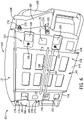
FIG. 5 is a rear view of the back pad assembly ofFIG. 1 . -
FIG. 6 is a top, rear, right isometric view of the back pad assembly ofFIG. 1 . -
FIG. 7 is a top, front, left isometric view of a mounting frame attached to a material handling vehicle according to an aspect of the present disclosure. -
FIG. 8A is a top, front, right isometric view of the back pad assembly ofFIG. 1 mounted to the mounting frame ofFIG. 7 . -
FIG. 8B is a top, front, right isometric view of an embodiment of a back pad assembly, according to some aspects of this disclosure, mounted to the mounting frame ofFIG. 7 . -
FIG. 9 is an enlarged view of a handle attached to the back pad assembly ofFIG. 6 . -
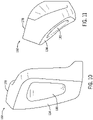
FIG. 10 is a front view of a handle of the back pad assembly ofFIG. 1 . -
FIG. 11 is a top view of the handle ofFIG. 10 . -
FIG. 12 is a left side view of the handle ofFIG. 10 . -
FIG. 13 is a right side view of another handle of the back pad assembly ofFIG. 1 . -
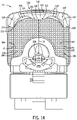
FIG. 14 is a top view of the back pad assembly ofFIG. 1 attached to a material handling vehicle according to an aspect of the present disclosure. -
FIG. 15 is a top, front, left view of the back pad assembly ofFIG. 8B . -
FIG. 16 is an cross-sectional left elevation view of the back pad assembly ofFIG. 8B mounted to the mounting frame ofFIG. 7 . -
FIG. 17A is a partial top, rear, right isometric view of the back pad assembly ofFIG. 1 , showing an embodiment of a bracket for a handle of the back pad assembly. -
FIG. 17B is a partial top, rear, right isometric view of the back pad assembly ofFIG. 1 , showing another embodiment of a bracket for a handle of the back pad assembly. -
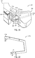
FIG. 18 is a partial top, rear, right isometric view of the back pad assembly ofFIG. 1 , showing an overlay of the bracket ofFIG. 17A and the bracket ofFIG. 17B . -
FIG. 19 is an isometric view of the bracket ofFIG. 17B for the handle assembly. - Before any aspect of the present disclosure are explained in detail, it is to be understood that the present disclosure is not limited in its application to the details of construction and the arrangement of components set forth in the following description or illustrated in the following drawings. The present disclosure is capable of other configurations and of being practiced or of being carried out in various ways. Also, it is to be understood that the phraseology and terminology used herein is for the purpose of description and should not be regarded as limiting. The use of "including," "comprising," or "having" and variations thereof herein is meant to encompass the items listed thereafter and equivalents thereof as well as additional items. Unless specified or limited otherwise, the terms "mounted," "connected," "supported," and "coupled" and variations thereof are used broadly and encompass both direct and indirect mountings, connections, supports, and couplings. Further, "connected" and "coupled" are not restricted to physical or mechanical connections or couplings.
- The following discussion is presented to enable a person skilled in the art to make and use aspects of the present disclosure. Various modifications to the illustrated configurations will be readily apparent to those skilled in the art, and the generic principles herein can be applied to other configurations and applications without departing from aspects of the present disclosure. Thus, aspects of the present disclosure are not intended to be limited to configurations shown, but are to be accorded the widest scope consistent with the principles and features disclosed herein. The following detailed description is to be read with reference to the figures, in which like elements in different figures have like reference numerals. The figures, which are not necessarily to scale, depict selected configurations and are not intended to limit the scope of the present disclosure. Skilled artisans will recognize the non-limiting examples provided herein have many useful alternatives and fall within the scope of the present disclosure.
- It is also to be appreciated that material handling vehicles are designed in a variety of classes and configurations to perform a variety of tasks. It will be apparent to those of skill in the art that the present disclosure is not limited to any specific material handling vehicle, and can also be provided with various other types of material handling vehicle classes and configurations, including for example, lift trucks, forklift trucks, reach trucks, SWING REACH® vehicles, turret trucks, side loader trucks, counterbalanced lift trucks, pallet stacker trucks, order pickers, transtackers, and man-up trucks, and can be commonly found in warehouses, factories, shipping yards, and, generally, wherever pallets, large packages, or loads of goods can be required to be transported from place to place. The various systems and methods disclosed herein are suitable for any of operator controlled, pedestrian controlled, remotely controlled, and autonomously controlled material handling vehicles.
- Material handling vehicles may require a back pad to provide comfort or support to an operator. Generally, the present disclosure provides a back pad assembly with an ergonomic design that allows an operator of a material handling vehicle to stand in a forward facing stance or a side stance. Further, the back pad assembly of the present disclosure is height-adjustable to allow for modification of a back pad for an operator's comfort.
-
FIGS. 1-4 illustrate one non limiting example of aback pad assembly 100 that may include aback pad 102. In some non-limiting examples, theback pad 102 may be formed by an over molding process. For example, theback pad 102 may be formed by over molding a foam pad over a welded armature (not shown). Theback pad 102 may include acenter portion 104, afirst side portion 106, and asecond side portion 108. Further, theback pad 102 may include a front side orfirst side 110 and a rear side orsecond side 112. Thecenter portion 104 may include acenter surface 114 on thefront side 110, thefirst side portion 106 may include a firstlateral surface 116 on thefront side 110, and thesecond side portion 108 may include a secondlateral surface 118 on thefront side 110. Thefirst side portion 106 and thesecond side portion 108 may be arranged on laterally-opposing sides of thecenter portion 104. As such, the firstlateral surface 116 and the secondlateral surface 118 may be disposed on laterally-opposing sides of thecenter surface 114. - As illustrated in
FIGS. 1-4 , thefirst side portion 106 defines a generally curved shape or profile, and thesecond side portion 108 defines a generally curved shape or profile. For example, in the illustrated non-limiting example, thefirst side portion 106 may define a generally concave shape or profile, and thesecond side portion 108 may define a generally concave shape or profile. In some non-limiting examples, thefirst side portion 106 and thesecond side portion 108 may be reflections of one another about thecenter portion 104. Thefirst side portion 106 may define a right outer edge or firstouter edge 124, and thesecond side portion 108 may define a left outer edge or secondouter edge 126. Thefirst side portion 106 may extend laterally from thecenter portion 104 to the firstouter edge 124, and thesecond side portion 108 may extend laterally from the center portion to the secondouter edge 126. - A first side handle or
first handle 128 may be coupled to thefirst side portion 106. Thefirst handle 128 defines afirst handle surface 130. A second side handle orsecond handle 132 may be coupled to thesecond side portion 108. The second side handle 132 defines asecond handle surface 134. The firstlateral surface 116 and thefirst handle surface 130 may combine to define a first curved portion orfirst side portion 106 of theback pad 102. That is, as shown advantageously inFIG. 2 , the firstlateral surface 116 and thefirst handle surface 130 may extend along a common curved shape or profile to define the curved shape or profile of thefirst side portion 106. Further, the secondlateral surface 118 and thesecond handle surface 134 may combine to define a curved portion orsecond side portion 108 of theback pad 102. That is, the secondlateral surface 118 and thesecond handle surface 134 may extend along a common curved shape or profile to define the curved shape or profile of thesecond side portion 108. - In some non-limiting examples, including as illustrated in
FIGS. 1-4 , thecenter portion 104 protrudes outward from theback pad 102. In the illustrated non-limiting example, thecenter surface 114 of thecenter portion 104 of theback pad 102 defines a substantially planar surface. In other non-limiting examples, thecenter surface 114 of thecenter portion 104 of theback pad 102 may define one or more curved surfaces. Thecenter portion 104 may protrude outward such that a topcentral edge 146 of thecenter portion 104 extends out further from theback pad 102 than a bottomcentral edge 148 of thecenter portion 104. In other words, thecenter surface 114 may be angled relative to a plane extending parallel to the topcentral edge 146 and perpendicular to a ground on which a material handling vehicle travels. - Turning to
FIGS. 5 and6 , theback pad assembly 100 may include aframework 150 coupled to theback pad 102. Theframework 150 may be attached to the rear side orsecond side 112 of theback pad 102. Theframework 150 may be attached to theback pad 102 via at least one back fastening element or a plurality of back fastening elements 151 (e.g., one or more bolts, or screws). Theframework 150 may include a central recessedregion 152 that is generally rectangular in shape. Theframework 150 may include a firstrear wall 154 and a secondrear wall 156 that may be arranged on laterally-opposing sides of the central recessedregion 152. The first and secondrear walls rear side 112. Further, the first and secondrear walls cutouts 155 that extend therethrough. The first and secondrear walls fastening elements 151 that attach the first and secondrear walls back pad 102. The central recessedregion 152 may be recessed relative to the first and secondrear walls frame 162 to extend within. - A
flange 140 may extend from theframework 150 to below abottom end 142 of the back pad 102 (e.g., in a direction away from the top central edge 146). Theflange 140 may be centrally located along thebottom end 142 of theback pad 102. Further, theflange 140 may include a mountingaperture 144. The mountingaperture 144 may be any size or shape and is configured to receive a fastening element therethrough. - The
framework 150 may include at least a first mountingbar 158 and a second mountingbar 160. The first mountingbar 158 and the second mountingbar 160 may define cylinders, or rectangular prisms, or any other shape. The first mountingbar 158 and the second mountingbar 160 may be vertically spaced apart and may be coupled to a mounting frame 162 (seeFIGS. 7 ,8A and8B ). Each of the first mountingbar 158 and the second mountingbar 160 may extend laterally across the central recessedregion 152 theframework 150. The first and second mounting bars 158, 160 extend laterally from the firstrear wall 154 to the secondrear wall 156. -
FIGS. 7 ,8A , and8B illustrates the mountingframe 162 fixed to aback rest 164 of amaterial handling vehicle 166. The mountingframe 162 may include a notchedsection 168 and anattachment section 170. The notchedsection 168 may be arranged vertically above (e.g., in a direction away from a floor on which thematerial handling vehicle 166 travels) theattachment section 170. As shown inFIG. 7 , the notchedsection 168 may include a plurality of vertically spacednotches 172. While the illustrated non-limiting example may include six laterally-opposed pairs of vertically spacednotches 172, in other non-limiting examples there may be more or less vertically spacednotches 172. Further, while the plurality of vertically spacednotches 172 in the illustrated example may be shaped to receive first and second mounting bars 158, 160 that are cylindrical in shape, in other non-limiting examples the plurality ofvertical notches 172 may be shaped to receive first and second mounting bars 158, 160 that are prismatic, or polygonal, in shape. Each of the first mountingbar 158 and the second mountingbar 160 may be configured to be received within a vertically-aligned pair ofnotches 172. Theback pad 102 and theframework 150 may be selectively displaced vertically to arrange the first and second mounting bars 158, 160 in a desired pair of thenotches 172 on the mountingframe 162 to set a height of theback pad 102. The mountingframe 162 provides theback pad assembly 100 with a plurality of discrete adjustable heights. Further, in non-limiting examples where there may be more vertically spacednotches 172, the mountingframe 162 provides more adjustability to an operator for configuring a height of theback pad assembly 100. In some non-limiting examples, only three vertically-spaced notches can be provided, allowing the back pad to be adjusted between only two heights, which can accommodate operators having a wide range of heights. -
FIG. 8A illustrates theback pad 102 and theframework 150 mounted to the mountingframe 162. Theattachment section 170 of the mountingframe 162 may include a plurality ofattachment apertures 174. The attachment apertures 174 may be vertically spaced apart and may be threaded. A fastening element (e.g., a screw or bolt) may be threaded through the mountingaperture 144 on theframework 150 and into theattachment apertures 174 on theattachment section 170 to secure theframework 150, and thereby theback pad 102, at a desired height on theback rest 164. Theattachment section 170 may include any number ofattachment apertures 174. - In other embodiments, a different back pad can be mounted to a mounting framework of a material handling vehicle. For example,
FIG. 8B illustrates aback pad 202 mounted to theframework 150. As illustrated, theback pad 202 can be generally similar to theback pad 102, and includes similar numbering for similar features. Theback pad 202 can thus include acenter portion 204, afirst side portion 206, and asecond side portion 208. Thecenter portion 204 may include acenter surface 214, thefirst side portion 206 may include a firstlateral surface 216, and thesecond side portion 208 may include a secondlateral surface 218. Thefirst side portion 206 and thesecond side portion 208 may be arranged on laterally-opposing sides of thecenter portion 204. As such, the firstlateral surface 216 and the secondlateral surface 218 may be disposed on laterally-opposing sides of thecenter surface 214. - As illustrated in
FIG. 8B , the first andsecond side portions second side portions other side portion center portion 204. Thefirst side portion 206 may define a right outer edge or firstouter edge 224, and thesecond side portion 208 may define a left outer edge or secondouter edge 226. Thefirst side portion 206 may extend laterally from thecenter portion 204 to the firstouter edge 224, and thesecond side portion 208 may extend laterally from the center portion to the secondouter edge 226. - A first side handle or
first handle 228 may be coupled to thefirst side portion 206. Thefirst handle 228 defines afirst handle surface 230. A second side handle orsecond handle 232 may be coupled to thesecond side portion 208. The second side handle 232 defines asecond handle surface 234. The firstlateral surface 216 and thefirst handle surface 230 may combine to define a first curved portion orfirst side portion 206 of theback pad 202. Further, the secondlateral surface 218 and thesecond handle surface 234 may combine to define a curved portion orsecond side portion 208 of theback pad 202. In the illustrated embodiment, thefirst handle 228 extends across a width of thefirst side portion 206 from thecenter portion 204 to the firstouter edge 224, and thesecond handle 232 extends across a width of thesecond side portion 208, from thecenter portion 204 to the secondouter edge 226. Each of the first andsecond handles handle aperture 280, which can receive, or partially receive, a hand of an operator while gripping therespective handle surface handle - In the illustrated non-limiting example of
FIG. 8B , thecenter portion 204 protrudes outward from theback pad 202. In the illustrated non-limiting example, thecenter surface 214 of thecenter portion 204 of theback pad 202 defines a concave profile, as could advantageously support the back of an operator in some operating positions and configurations. - Side handles of a back pad for a material handling vehicle may experience more direct contact with a user than a body of the back pad, and it can thus be advantageous to provide systems for removing side handles from a back pad, allowing the side handles to be independently replaced without the need to simultaneously replace the entire back pad. Referring now to
FIG. 9 , the first and second side handles 128, 132 of theback pad assembly 100 each may includearms 176 that are vertically spaced from one another and that extend from arear handle surface 178 of the first and second side handles 128, 132. Therear handle surface 178 may be arranged on therear side 112 of theback pad 102. A fastening element 179 (e.g., a screw or bolt) may be installed through thearms 176 and into theframework 150 to couple the first and second side handles 128, 132 to theframework 150. The first and second side handles 128, 132 may be removably coupled to theback pad 102 via selective installation and removal of thefastening elements 179, thus allowing for independent replacement or maintenance of the first and second side handles 128, 132, without the need for a corresponding replacement of theback pad 102. - Arms for connecting a side handle of a back pad to a framework can be integrally formed with a handle bracket, which can provide structure and durability to a side handle. In this regard,
FIGS. 17A and 17B illustrate non-limiting examples of aback pad 102 includinghandle brackets FIG. 17A , afirst handle bracket 177a can be provided, which can provide internal structure to thefirst side handle 128. Thefirst handle bracket 177a can define a generally U-shaped profile, as can approximately match a curved profile of thehandle surface 130.Arms first handle bracket 177a can extend outwardly from thefirst side handle 128 and can include one ormore apertures 181 for receivingcorresponding fastening elements 179. In the illustrated embodiment (as also illustrated inFIGS. 6 and9 ), thearms first handle bracket 177a are substantially parallel to each other and are both configured to be fastened to a firstplanar surface 157 of theframework 150.FIG. 17B , illustrates another non-limiting example, showing asecond handle bracket 177b, having afirst arm 176b which can be longer than asecond arm 176, the second arm being identical to thesecond arm 176 of thefirst handle bracket 177a. Further, as shown, thearms bracket 177b are not parallel, and thefirst arm 176b can be configured to secure thebracket 177b (and thus the first handle 128) to a secondplanar surface 159 of theframework 150, the secondplanar surface 159 being disposed at an angle relative to the firstplanar surface 157. Thesecond arm 176 can be configured to secure thebracket 177b (and thus the first handle 128) to the firstplanar surface 157. -
FIG. 18 illustrates an overlay of thefirst handle bracket 177a and thesecond handle bracket 177b. As shown, thebrackets second arms 176. As shown, thefirst arm 176b can extend further along theframework 150 than thefirst arm 176a of thefirst bracket 177a. Thefirst arm 176a of thesecond bracket 177b can further include one or multiple bends which can allow thesecond bracket 177b to match a profile of thecorresponding surface 130 of thefirst handle 128, while also positioning thefirst arm 176b to be fastened to the secondplanar surface 159. While thebrackets first handle 128, one of skill in the art will appreciate that handle brackets, similar to, identical to, or being a mirror image ofhandle brackets handles bracket 177b, further illustrated inFIG. 19 , can be particularly advantageous for use with thehandles back pad assembly 200, as the brackets can provide support for a handle having a longer profile, and can allow thehandles respective side portions brackets different handle apertures - As shown in
FIGS. 10-12 , the second side handle 132 is illustrated in further detail. The second side handle 132 is similar to the first handle 128 (seeFIG. 1 ), with like features identified using the same reference numerals, except that the second side handle 132 is a mirror image of thefirst handle 128. Thesecond handle surface 134 defines a generally curved shape or profile. For example, in the illustrated non-limiting example, thesecond handle surface 134 may define a generally concave shape or profile that continues the general concave shape or profile of the secondlateral surface 118. Thesecond handle surface 134 and the secondlateral surface 118 may combine to form the generally curved profile of the secondcurved portion 108. The second side handle 132 may include a hole or ahandle aperture 180 that extends therethrough. Theaperture 180 may be configured to receive a hand of an operator (not shown). Further, the second handle may include a mating surface or notch or recessedhandle surface 182 that extends from therear handle surface 178. Themating surface 182 is configured to receive the framework 150 (seeFIG. 9 ). Further, and as shown in the illustrated non-limiting example, themating surface 182 may be dimensioned to conform to a shape defined by theframework 150.FIG. 13 illustrates thefirst side handle 128, which, as shown, includes the same features as thesecond side handle 132, including themating surface 182, and therear handle surface 178. - Referring now to
FIG. 14 , thematerial handling vehicle 166 may include anoperator compartment 184 that defines an active zone 186. The active zone 186 may be where an operator stands on anoperator platform 187 to operate thematerial handling vehicle 166. The active zone 186 may include aperimeter 188 with a right perimeter side orfirst perimeter side 190 and a left perimeter side orsecond perimeter side 192. Thefirst perimeter side 190 may define a first vertical plane PI that extends perpendicularly from theoperator platform 187. The first vertical plane PI may intersect the firstouter edge 124 of thefirst side portion 106. Thesecond perimeter side 192 may define a second vertical plane P2 that extends perpendicularly from theoperator platform 187. The second vertical plane P2 may intersect the secondouter edge 126 of thesecond side portion 108. - The
center portion 104 formed in theback pad 102 can urge an operator towards acontrol handle 198 on thematerial handling vehicle 166 during a forward motion of travel. A compartment length D1 may be measured from thecenter surface 114 to thecontrol handle 198. The compartment length D1 may be any distance depending on how far thecenter portion 104 protrudes from theback pad 102. The first and secondcurved portions back pad 102 allow an operator to operate thematerial handling vehicle 166 in a side stance when operating thematerial handling vehicle 166 in a non-forward motion of travel. Therefore, the operator may stand in at least three operating configurations in the active zone with the ergonomic design of theback pad assembly 100 of the present disclosure: a forward standing configuration, a first side-stance configuration, or a second side-stance configuration. Additionally, the first and second side handles 128, 132 can provide additional support to an operator in a side stance position. In the first and second side-stance configuration, a side of the operator can be at least partially received in one of the firstlateral surface 116, or secondlateral surface 118, and the operator can grasp thehandle back pad 102 can be spaced at a height to allow an arm of the operator to rest on a top of thecenter portion 104 of theback pad 102 when the operator is in the first or second side stance. Accordingly, in some non-limiting examples, the vertically spacednotches 172 can be positioned to allow the back pad to be set to a height with the topcentral edge 146 of the back pad at about 40 to about 45 inches, the topcentral edge 146 of the back pad being about 1000 millimeters to about 1150 millimeters above theoperator platform 187. - In some non-limiting examples, handles of a back pad can provide multiple grip configurations for an operator of a material handling vehicle. For example,
FIG. 15 illustrates theback pad assembly 200, showing backpad 202 mounted to aback rest 164 of thematerial handling vehicle 166. The back rest has asurface 167 facing generally toward theback pad 202. As shown, thefirst handle surface 230 of thefirst handle 228 has a horizontalgripping portion 230a which extends in a horizontal direction (e.g., approximately parallel to theoperator platform 187 illustrated inFIG. 14 ). Thefirst handle surface 230 further has a verticalgripping portion 230b, which extends in a generally vertical direction. The horizontalgripping portion 230a and the verticalgripping portion 230b can thus provide different grip configurations for an operator. The horizontalgripping portion 230a can be positioned closer to thesecond side portion 208 than the verticalgripping portion 230b and can therefore provide a gripping location for an operator standing in a side-stance in thesecond side portion 208. Additionally, the horizontalgripping portion 230a can provide a gripping location for an operator whose arm is resting above theback pad 202. Further, the horizontal portion can be spaced apart from thesurface 167 of theback rest 164 by a distance D2. The distance D2 can be a distance that is configured to allow an operator's hand to be at least partially received between thehorizontal portion 230a and theback rest 164. An operator could thus place their hand into the space between theback rest 164 and the horizontalgripping portion 230a, with their fingers extending through theaperture 280 to grip thehandle 228 in the horizontal gripping configuration. It should be appreciated that the above disclosure can apply equally to thesecond handle 232, which can be a mirror of thefirst handle 228 and can thus include multiple portions of thesecond handle surface 234 allowing for multiple different gripping configurations for an operator. - A back pad assembly for a material handling vehicle can be positioned at an angle, relative to a vertical axis. For example,
FIG. 16 illustrates theback pad assembly 200, and a vertical axis A. An installation axis B of the back pad assembly can be parallel to a planar surface of a central recessedregion 252 of the back pad assembly. As shown, an angle C is defined between the axis B and the vertical axis A, and the back pad assembly may thus allow an operator to recline slightly against theback pad 202 during operation of the material handling vehicle 166 (seeFig. 15 ). In other embodiments, the axis B can be defined as an axis parallel to an elongate direction of the mountingframe 162, or a surface thereof. - Within this specification aspects of the present disclosure have been described in a way which enables a clear and concise specification to be written, but it is intended and will be appreciated that aspects of the present disclosure may be variously combined or separated without parting from the invention. For example, it will be appreciated that all preferred features described herein are applicable to all aspects of the invention described herein.
- Thus, while the invention has been described in connection with particular aspects and examples, the invention is not necessarily so limited, and that numerous other aspects, examples, uses, modifications and departures from the aspects, examples and uses are intended to be encompassed by the claims attached hereto. The entire disclosure of each patent and publication cited herein is incorporated by reference, as if each such patent or publication were individually incorporated by reference herein.
- Various features and advantages of the invention are set forth in the following claims.
Claims (15)
- A back pad assembly for a material handling vehicle, the back pad assembly comprising:a back pad including a center portion, a first side portion, and a second side portion, wherein the first side portion defines a first curved profile and the second side portion defines a second curved profile, the first curved profile and the second curved profile being arranged on laterally-opposing sides of the center portion;a framework including a first mounting bar and a second mounting bar, wherein the framework is coupled to the back pad; anda mounting frame,wherein the first and second mounting bars are adjustably supported by the mounting frame to enable the back pad to be selectively mounted at varying heights along the mounting frame.
- The back pad assembly of claim 1, wherein the back pad is formed by over molding a foam pad.
- The back pad assembly of claim 1 or 2, wherein the back pad includes at least one side handle coupled to the back pad, preferably the at least one side handle is removably coupled to the framework, further preferably the at least one side handle comprises a bracket having a first arm and a second arm, wherein the first arm and the second arm are configured to be secured to at least a first planar surface of the framework to couple the at least one side handle to the back pad.
- The material handling vehicle of claim 3, wherein the first arm is configured to be secured to a second planar surface of the framework, the second planar surface being positioned at an angle relative to the first planar surface.
- The material handling vehicle of any of the claims 3-4, wherein the at least one side handle includes a vertical gripping portion and a horizontal gripping portion.
- A material handling vehicle comprising:an operator compartment that defines an active zone with a perimeter;a back rest; anda back pad, the back pad including a first side portion and a second side portion with generally curved profiles arranged on laterally-opposing sides of a center portion,wherein the center portion protrudes from the back pad toward a control handle of the material handling vehicle,wherein a first side of the perimeter defines a first vertical plane that intersects a first outer edge of the first side portion, andwherein a second side of the perimeter defines a second vertical plane that intersects a second outer edge of the second side portion, preferably the back rest includes a mounting frame, and the back pad is mounted to the mounting frame.
- The material handling vehicle of claim 6, wherein the mounting frame includes a notched section that includes a plurality of vertically spaced notches.
- The material handling vehicle of claim 6 or 7, wherein the mounting frame further includes an attachment section with a plurality of vertically spaced threaded apertures.
- The material handling vehicle of any of the claims 6 - 8, further comprising a framework including a first mounting bar and a second mounting bar, wherein the framework is coupled to the back pad.
- The material handling vehicle any of the claims 6 - 9, wherein the back pad includes at least one side handle coupled to the back pad, preferably the at least one side handle is removably coupled to the framework.
- A material handling vehicle comprising:a back pad including a center surface, a first lateral surface, and a second lateral surface, wherein the first lateral surface and the second lateral surface are disposed on laterally opposing sides of the center surface;a first handle coupled to a first side of the back pad and defining a first handle surface; anda second handle coupled to a second side of the back pad and defining a second handle surface,wherein the first lateral surface and the first handle surface combine to define a first curved portion of the back pad, andwherein the second lateral surface and the second handle surface combine to define a second curved portion of the back pad,preferably the material handling vehicle is further comprising a framework including a first mounting bar and a second mounting bar, wherein the framework is coupled to the back pad.
- The material handling vehicle of claim 11, further comprising a mounting frame, wherein the first and second mounting bars are adjustably supported by the mounting frame to enable the back pad to be selectively mounted at varying heights along the mounting frame.
- The material handling vehicle of claim 12, wherein the mounting frame includes a notched section that includes a plurality of vertically spaced notches.
- The material handling vehicle of any of the claims 11 - 13, wherein the first handle and the second handle are removably coupled to the framework.
- The material handling vehicle of any of the claims 11-14, wherein the first handle and the second handle include a notch in a rear of the first handle and the second handle, the notch being configured to receive the framework.
Applications Claiming Priority (1)
| Application Number | Priority Date | Filing Date | Title |
|---|---|---|---|
| US202163209863P | 2021-06-11 | 2021-06-11 |
Publications (2)
| Publication Number | Publication Date |
|---|---|
| EP4101690A1 true EP4101690A1 (en) | 2022-12-14 |
| EP4101690B1 EP4101690B1 (en) | 2026-04-29 |
Family
ID=82021066
Family Applications (1)
| Application Number | Title | Priority Date | Filing Date |
|---|---|---|---|
| EP22178597.5A Active EP4101690B1 (en) | 2021-06-11 | 2022-06-13 | Back pad assembly for a material handling vehicle |
Country Status (6)
| Country | Link |
|---|---|
| US (1) | US12252047B2 (en) |
| EP (1) | EP4101690B1 (en) |
| CN (1) | CN115465812A (en) |
| AU (1) | AU2022203994A1 (en) |
| CA (1) | CA3162805A1 (en) |
| MX (1) | MX2022007147A (en) |
Families Citing this family (3)
| Publication number | Priority date | Publication date | Assignee | Title |
|---|---|---|---|---|
| USD1028744S1 (en) * | 2020-03-06 | 2024-05-28 | The Raymond Corporation | Sensor housing |
| US11849667B2 (en) * | 2021-12-30 | 2023-12-26 | Exmark Manufacturing Company Incorporated | Magnetic panel for utility vehicle |
| USD1091208S1 (en) * | 2022-06-10 | 2025-09-02 | The Raymond Corporation | Back pad |
Citations (4)
| Publication number | Priority date | Publication date | Assignee | Title |
|---|---|---|---|---|
| US4572578A (en) * | 1984-08-08 | 1986-02-25 | Perkins Patricia A | Back rest |
| US4834455A (en) * | 1988-07-14 | 1989-05-30 | Proctor Joy E | Orthopedic vehicle seat |
| FR2928612A1 (en) * | 2008-03-17 | 2009-09-18 | Linde Material Handling Gmbh | Load transporting tractor, has frame installation extending in its longitudinal direction towards rear in vertical zone above anchoring device, and arranged at interior of its maximum longitudinal extension and maximum transversal extension |
| CN212243648U (en) * | 2020-04-22 | 2020-12-29 | 创呈工业设计(上海)有限公司 | Lifting type back rest armrest assembly for electric vehicle |
Family Cites Families (40)
| Publication number | Priority date | Publication date | Assignee | Title |
|---|---|---|---|---|
| US5344211A (en) * | 1993-08-05 | 1994-09-06 | Riyaz Adat | Adjustable backrest |
| CA2244955C (en) * | 1997-08-13 | 2006-12-05 | Magna Interior Systems Inc. | Adjustable comfort seat |
| JP3834949B2 (en) | 1997-08-25 | 2006-10-18 | トヨタ紡織株式会社 | Vehicle seat and method for manufacturing the same |
| WO1999010270A1 (en) * | 1997-08-28 | 1999-03-04 | Crown Equipment Corporation | Materials handling vehicle having an expanded operator's compartment |
| MXPA00000806A (en) | 1997-08-28 | 2003-09-10 | Crown Equip Corp | Operator's station for a lift truck including three position seat assembly. |
| DE69803469T2 (en) | 1997-08-28 | 2002-09-12 | Crown Equipment Corp., New Bremen | DRIVER'S STAND FOR TRUCKS WITH THREE-POSITION ADJUSTABLE SEAT |
| USD537226S1 (en) | 2003-10-10 | 2007-02-20 | Jungheinrich Aktiengesellshcaft | Forklift truck |
| JP4961865B2 (en) | 2005-10-07 | 2012-06-27 | 株式会社豊田自動織機 | Backrest structure for standing driver's seat in industrial vehicles |
| US7914078B2 (en) | 2005-10-31 | 2011-03-29 | Deere & Company | Adjustable lower seat for use with a stand and lean type backrest |
| US7793979B2 (en) | 2006-02-03 | 2010-09-14 | Crown Equipment Corporation | Operator backrest and knee support pad for a materials handling vehicle |
| USD544174S1 (en) | 2006-04-11 | 2007-06-05 | Crown Equipment Corporation | Stand-up counterbalance lift truck |
| DE102007049392A1 (en) | 2007-05-29 | 2008-12-04 | Linde Material Handling Gmbh | fork-lift truck |
| CA2683477A1 (en) | 2008-10-29 | 2010-04-29 | The Raymond Corporation | Vehicle seat assembly |
| USD608522S1 (en) | 2009-03-13 | 2010-01-19 | Crown Equipment Corporation | Side entry pallet truck |
| USD618945S1 (en) | 2009-11-12 | 2010-07-06 | John Tanaka | Airbag lumbar support pillow |
| DE102011018801A1 (en) | 2011-04-27 | 2012-10-31 | Still Gmbh | Industrial truck with a driver's seat forming a sitting and standing aid |
| WO2012166084A1 (en) | 2011-05-27 | 2012-12-06 | Husqvarna Consumer Outdoor Products N.A., Inc. | Lawn care vehicle adjustable seat |
| USD717514S1 (en) | 2012-06-29 | 2014-11-11 | Nmhg Oregon, Llc | Lift truck |
| US9235553B2 (en) | 2012-10-19 | 2016-01-12 | Hand Held Products, Inc. | Vehicle computer system with transparent display |
| US8905183B2 (en) | 2013-03-14 | 2014-12-09 | The Raymond Corporation | Contoured backrest with integrated control module for use with a material handling vehicle |
| USD756589S1 (en) | 2014-08-06 | 2016-05-17 | Jungheinrich Aktiengesellschaft | Fork lift truck |
| DE102014114428A1 (en) | 2014-10-06 | 2016-04-07 | Jungheinrich Aktiengesellschaft | Industrial truck with a stand |
| USD790238S1 (en) | 2015-08-07 | 2017-06-27 | Dg International Holdings Limited | Footrest |
| USD805323S1 (en) | 2015-09-03 | 2017-12-19 | King Chan | Seat cushion |
| USD790255S1 (en) | 2016-04-22 | 2017-06-27 | Shenzhen Qishengxieneng Electronic Co., Ltd. | Cushion |
| US9999304B2 (en) | 2016-06-03 | 2018-06-19 | Max Krishtul | Lumbar support cushion |
| USD793770S1 (en) | 2016-06-03 | 2017-08-08 | Max Krishtul | Lumbar support cushion |
| USD846325S1 (en) | 2017-09-05 | 2019-04-23 | Hsuan-Chin Tsai | Chair back |
| USD885085S1 (en) | 2017-12-01 | 2020-05-26 | Davinci Ii Csj, Llc | Seat cushion |
| USD903351S1 (en) | 2019-09-24 | 2020-12-01 | Wuyi instinct outdoor products Co., Ltd. | Air lounger |
| TWD202962S (en) | 2019-10-25 | 2020-03-01 | 鼎鋒國際企業股份有限公司 | Chair back (1) |
| USD915104S1 (en) | 2019-11-04 | 2021-04-06 | Jingang YANG | Cushion |
| USD925672S1 (en) | 2019-12-19 | 2021-07-20 | Innova Products, Inc. | Ankle holder for an inversion therapy table |
| US11191363B2 (en) | 2020-03-11 | 2021-12-07 | London Luxury Llc | Dual-use support cushion |
| CN114056200B (en) | 2020-08-07 | 2026-01-13 | 明门瑞士股份有限公司 | Infant carrier and quick-release headrest thereof |
| USD980648S1 (en) | 2020-09-04 | 2023-03-14 | Wei Shen | Car cushion |
| USD972336S1 (en) | 2021-03-05 | 2022-12-13 | Oregon Health & Science University | Infant feeding positioning cushion |
| USD985876S1 (en) | 2021-05-11 | 2023-05-09 | The Raymond Corporation | Vehicle console |
| US20230133956A1 (en) | 2021-11-01 | 2023-05-04 | Philip Root | Bone conduction body support device |
| USD994408S1 (en) | 2023-05-22 | 2023-08-08 | Qiuya Zhao | Backrest |
-
2022
- 2022-06-09 AU AU2022203994A patent/AU2022203994A1/en active Pending
- 2022-06-10 CA CA3162805A patent/CA3162805A1/en active Pending
- 2022-06-10 MX MX2022007147A patent/MX2022007147A/en unknown
- 2022-06-13 CN CN202210662169.8A patent/CN115465812A/en active Pending
- 2022-06-13 US US17/838,528 patent/US12252047B2/en active Active
- 2022-06-13 EP EP22178597.5A patent/EP4101690B1/en active Active
Patent Citations (4)
| Publication number | Priority date | Publication date | Assignee | Title |
|---|---|---|---|---|
| US4572578A (en) * | 1984-08-08 | 1986-02-25 | Perkins Patricia A | Back rest |
| US4834455A (en) * | 1988-07-14 | 1989-05-30 | Proctor Joy E | Orthopedic vehicle seat |
| FR2928612A1 (en) * | 2008-03-17 | 2009-09-18 | Linde Material Handling Gmbh | Load transporting tractor, has frame installation extending in its longitudinal direction towards rear in vertical zone above anchoring device, and arranged at interior of its maximum longitudinal extension and maximum transversal extension |
| CN212243648U (en) * | 2020-04-22 | 2020-12-29 | 创呈工业设计(上海)有限公司 | Lifting type back rest armrest assembly for electric vehicle |
Also Published As
| Publication number | Publication date |
|---|---|
| EP4101690B1 (en) | 2026-04-29 |
| AU2022203994A1 (en) | 2023-01-05 |
| CA3162805A1 (en) | 2022-12-11 |
| US20220396188A1 (en) | 2022-12-15 |
| US12252047B2 (en) | 2025-03-18 |
| CN115465812A (en) | 2022-12-13 |
| MX2022007147A (en) | 2023-01-16 |
Similar Documents
| Publication | Publication Date | Title |
|---|---|---|
| EP4101690A1 (en) | Back pad assembly for a material handling vehicle | |
| CN101479180B (en) | Overhead guard for materials handling vehicle | |
| NZ199019A (en) | Adjustable wall mounted rails for small component bins | |
| US6899347B2 (en) | Ergonomic merchandiser | |
| US20200317150A1 (en) | Material Handling Vehicle Having a Multi-Piece Bumper Assembly | |
| CA2979284C (en) | Storage system and article retrieving method | |
| US20200239291A1 (en) | Industrial truck with stand-on platform | |
| KR20200016022A (en) | A fastening frame for pallet rack connection | |
| US11840436B2 (en) | Mast and supplementary object detection system for a material handling vehicle | |
| WO2001056835A1 (en) | Flat goods clamping and transporting apparatus | |
| US8167151B2 (en) | Forkable base stand | |
| HK40084631A (en) | Back pad assembly for a material handling vehicle | |
| JP6155672B2 (en) | Battery pack | |
| US20240092619A1 (en) | Work assist system for an industrial vehicle | |
| GB2347132A (en) | Lift truck | |
| CN210885151U (en) | Fork device for stacking | |
| WO2020099899A2 (en) | Transport robot for manufacturing lines | |
| US20250229818A1 (en) | Trolley chassis system | |
| US11285985B2 (en) | Control device | |
| JP7243679B2 (en) | Goods storage shelf | |
| JP4085348B2 (en) | Rack for automatic warehouse | |
| KR0164195B1 (en) | Back panel change work jig of car | |
| CA2515874A1 (en) | Merchandiser assembly | |
| HK40037919A (en) | Mast and supplementary object detection system for a material handling vehicle | |
| JP4186111B2 (en) | Article storage shelf structure for warehouse |
Legal Events
| Date | Code | Title | Description |
|---|---|---|---|
| PUAI | Public reference made under article 153(3) epc to a published international application that has entered the european phase |
Free format text: ORIGINAL CODE: 0009012 |
|
| STAA | Information on the status of an ep patent application or granted ep patent |
Free format text: STATUS: THE APPLICATION HAS BEEN PUBLISHED |
|
| AK | Designated contracting states |
Kind code of ref document: A1 Designated state(s): AL AT BE BG CH CY CZ DE DK EE ES FI FR GB GR HR HU IE IS IT LI LT LU LV MC MK MT NL NO PL PT RO RS SE SI SK SM TR |
|
| STAA | Information on the status of an ep patent application or granted ep patent |
Free format text: STATUS: REQUEST FOR EXAMINATION WAS MADE |
|
| 17P | Request for examination filed |
Effective date: 20230614 |
|
| RBV | Designated contracting states (corrected) |
Designated state(s): AL AT BE BG CH CY CZ DE DK EE ES FI FR GB GR HR HU IE IS IT LI LT LU LV MC MK MT NL NO PL PT RO RS SE SI SK SM TR |
|
| STAA | Information on the status of an ep patent application or granted ep patent |
Free format text: STATUS: EXAMINATION IS IN PROGRESS |
|
| 17Q | First examination report despatched |
Effective date: 20240507 |
|
| GRAP | Despatch of communication of intention to grant a patent |
Free format text: ORIGINAL CODE: EPIDOSNIGR1 |
|
| STAA | Information on the status of an ep patent application or granted ep patent |
Free format text: STATUS: GRANT OF PATENT IS INTENDED |
|
| INTG | Intention to grant announced |
Effective date: 20251117 |
|
| GRAS | Grant fee paid |
Free format text: ORIGINAL CODE: EPIDOSNIGR3 |
|
| GRAA | (expected) grant |
Free format text: ORIGINAL CODE: 0009210 |
|
| STAA | Information on the status of an ep patent application or granted ep patent |
Free format text: STATUS: THE PATENT HAS BEEN GRANTED |
|
| AK | Designated contracting states |
Kind code of ref document: B1 Designated state(s): AL AT BE BG CH CY CZ DE DK EE ES FI FR GB GR HR HU IE IS IT LI LT LU LV MC MK MT NL NO PL PT RO RS SE SI SK SM TR |
|
| REG | Reference to a national code |
Ref country code: CH Ref legal event code: F10 Free format text: ST27 STATUS EVENT CODE: U-0-0-F10-F00 (AS PROVIDED BY THE NATIONAL OFFICE) Effective date: 20260429 |
|
| RIN1 | Information on inventor provided before grant (corrected) |
Inventor name: MILLER, DANIEL B. Inventor name: SMILEY, GREGORY W. Inventor name: YAHNER, JOSEPH T. Inventor name: LUTZ, KURT R. Inventor name: WERNER, KURT R. Inventor name: KONIECZNY, MICHAEL W. Inventor name: WITKOWSKI III, FRANK J. Inventor name: RYAN, HOWARD SCOTT |