EP4101612A1 - Router power tool - Google Patents
Router power tool Download PDFInfo
- Publication number
- EP4101612A1 EP4101612A1 EP22177755.0A EP22177755A EP4101612A1 EP 4101612 A1 EP4101612 A1 EP 4101612A1 EP 22177755 A EP22177755 A EP 22177755A EP 4101612 A1 EP4101612 A1 EP 4101612A1
- Authority
- EP
- European Patent Office
- Prior art keywords
- router
- lever
- base
- adjustment
- threaded rod
- Prior art date
- Legal status (The legal status is an assumption and is not a legal conclusion. Google has not performed a legal analysis and makes no representation as to the accuracy of the status listed.)
- Granted
Links
Images






Classifications
-
- B—PERFORMING OPERATIONS; TRANSPORTING
- B27—WORKING OR PRESERVING WOOD OR SIMILAR MATERIAL; NAILING OR STAPLING MACHINES IN GENERAL
- B27C—PLANING, DRILLING, MILLING, TURNING OR UNIVERSAL MACHINES FOR WOOD OR SIMILAR MATERIAL
- B27C5/00—Machines designed for producing special profiles or shaped work, e.g. by rotary cutters; Equipment therefor
- B27C5/10—Portable hand-operated wood-milling machines; Routers
Definitions
- the present invention relates to power tools, especially routers. There are various existing power tools. It is desired to provide a power tool with an efficient depth adjustment mechanism.
- a first aspect of the present invention provides a router according to Claim 1 of the appended claims.
- the router includes a router body; a motor housed in the router body; an output member drivable by the motor; and a router base adjustably connected to the router body.
- the router base includes a mounting rod, a latching lever and an adjustment lever. The latching lever and the adjustment lever may both be mounted on the mounting rod.
- the latching lever may be rotatable about a first axis and the adjustment lever is rotatable about a second axis.
- the second axis may be transverse to the first axis.
- the first axis may be transverse to a longitudinal axis of the mounting rod.
- the second axis may be along the longitudinal axis of the rod.
- the router body may further include a threaded rod extending along an outer surface of the router body.
- the router body may further include an adjustment knob.
- the adjustment knob may be connected to the threaded rod and rotation of the adjustment knob causes the threaded rod to rotate.
- the adjustment lever may include adjustment lever threads configured to selectively engage the threaded rod.
- the adjustment lever may be biased in a direction of the adjustment lever threads engaging with the threaded rod.
- the latching lever may be rotatable from a closed position to an open position.
- the router base When the latching lever is in the closed position the router base may be held in place on the router body.
- the router base When the latching lever is in the open position the router base may be movable relative to the router body.
- the latching lever When the latching lever is in the closed position it may cover a portion of the adjustment lever.
- the router base may further include a battery receptacle configured to receive a removable battery pack.
- the router includes a router body; a motor housed in the router body; an output member configured to hold a router bit, the output member being drivable by the motor; and a router base adjustably connected to the router body.
- the router base includes a latching lever and an adjustment lever.
- the latching lever is rotatable between a closed position in which the router base is held in place on the router body and an open position in which the router base is movable relative to the router body.
- the latching lever is transverse to the adjustment lever.
- the router base has an upper end and a lower end; the upper end of the router base engages the router body; the lower end of the router base is adjacent to a workpiece; the adjustment lever has a first end and a second end; the second end of the adjustment lever includes threads; and the first end of the adjustment lever is closer to the lower end of the router base than the second end of the adjustment lever is to the router base.
- the first end of the adjustment lever may be configured to be actuated by a user to rotate the adjustment lever.
- the second end of the adjustment lever may extend above a top of the upper end of the router base.
- the first end of the adjustment lever may be below the top of the upper end of the router base.
- the router base may further comprise a pair of tabs and a mounting rod extending through the pair of tabs.
- the adjustment lever may be mounted on the mounting rod.
- the latching lever may be mounted on the mounting rod.
- a router including a router body; a motor housed in the router body; an output member configured to hold a router bit, the output member being drivable by the motor; and a router base adjustably connected to the router body.
- the router body includes a threaded rod extending along an outside of the router body.
- the router base includes a latching lever an adjustment lever. The latching lever is rotatable between a closed position in which the router base is held in place on the router body and an open position in which the router base is movable relative to the router body.
- the adjustment lever may include threads configured to selectively engage the threaded rod.
- the latching lever may partially cover the adjustment lever when the latching lever is in the closed position.
- any feature, including any preferred or other optional feature, of any aspect or embodiment of the invention may be a feature, including a preferred or other optional feature, of any other aspect or embodiment of the invention.
- FIG. 1 An exemplary embodiment of a router according to the present application is shown in Figs. 1-12 .
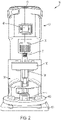
- Figs. 1 and 2 illustrate a router 10 including a body 50 assembled with an adjustable base 100.
- Fig. 1 is a perspective view of the router 10 and Fig. 2 is a front view of the router.
- Fig. 3 illustrates a perspective view of the router body 50 without the base 100.
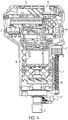
- Fig. 4 illustrates the router body 50 with the housing partially removed to show internal components.
- Fig. 5 illustrates the base 100 alone.
- the router 10 includes a router body 50 and an adjustable base 100 connected to the router body 50.
- the router body 50 includes a battery receptacle portion 55.
- the battery receptacle portion 55 is configured to receive the power tool battery pack 200 shown in Fig. 12 .
- the power tool battery pack 200 may be a twenty-volt lithium-ion removable battery pack that is configured to power a variety of tools such as sanders, saws, drills, impact drivers and the like, in addition to the router 10.
- the battery receptacle portion 55 is at a top of the router body 50.
- the router body 50 includes a power switch 60.
- the power switch 60 is used to activate and deactivate the router 10.
- the router body also includes a depth adjustment knob 70.
- the depth adjustment knob 70 can be rotated by a user.
- the depth adjustment knob 70 is connected to a threaded rod 71 so that when a user rotates the depth adjustment knob 70, the threaded rod 71 rotates along with the depth adjustment knob 70. As shown in Fig. 3 , for example, the threaded rod 71 extends vertically along the lower length of the router body 50.
- the router body 50 includes an output member 75.
- the output is a router chuck 75 that holds various router bits.
- the router chuck 75 rotates about a vertical axis when the router 10 is activated so that the motor is activated and drives the chuck 75.
- the router body 50 also includes a spindle lock 76.
- the spindle lock 76 can be depressed by a user so that the spindle lock 76 extends into the spindle on which the chuck 75 is mounted. That holds the spindle and chuck 75 in place so that a router bit can be removed or attached to the chuck 75.
- Fig. 4 is a side view of the router body 50 with a housing shell removed.
- the battery receptacle portion 55 includes electrical connectors 56 for electrically connecting with the battery pack 200.
- Wires 57 connect the components such as the electrical connectors 56, motor 80, switch 60 and rotatable dial 61.
- the dial 61 is rotatable to adjust the speed of the motor 80, as can be done through a potentiometer.
- the router 10 includes a motor 80. When the router 80 is activated, power is provided to the motor 80.
- the motor drives spindle 77 on which the chuck 75 is mounted so as to rotatably drive the chuck 75 and any router bit held by the chuck 75.
- a fan 78 may be mounted on the spindle 77 in order to provide a cooling effect.
- the spindle lock 76 may be pressed to engaged with the spindle 77 and prevent rotation of the spindle 77.
- the spindle lock 76 is biased by a biasing member away from the spindle 77 and a user must depress the spindle lock 76 and overcome the biasing force to engage it with the spindle 77.
- the biasing member may be one or more springs.
- the adjustable base 100 is shown in various figures, including Figs. 1 , 2 , 5 and 6 .
- the adjustable base 100 is configured to be selectively clamped onto the router body 50.
- the base 100 includes a cylindrical sleeve 101. At a bottom of the cylindrical sleeve 101, there is a ring 102.
- the ring 102 is attached to a foot plate 103.
- the foot plate 103 can be placed on a workpiece, such as a piece of wood. Adjusting the position of the base 100 changes the depth of a cut performed by a router bit driven by the output member 75.
- the base 100 includes a rotatable latch lever 110.
- the sleeve 101 has a pair of projections or tabs 105.
- a rod 120 extends through holes in the projections 105.
- One end of the rod includes a vertical through hole and a pin 125 extends through the rod 120 and engages with the lever 110.
- the lever 110 is rotatable about the pin 125.
- a macro-adjustment lever 130 is also mounted on the rod 120.
- the macro-adjustment lever has a first end 131 configured to be pressed by a user to rotate the lever 130.
- the second end 132 of the lever 130 is selectively engaged with the threaded rod 71.
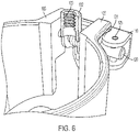
- the second end 132 of the lever 130 includes threads 133 for engaging with the threaded rod 71.
- a torsion spring 135 biases the macro-adjustment lever 130 in a direction of the threads 133 at the second end 132 of the lever 130 into engagement with the threaded rod 71.
- a user may push on the first end 131 in order to rotate the lever 130 and dis-engage the threads 133 from the threaded rod 71.
- the adjustment lever 130 is transverse to the latching lever 110. In the exemplary embodiment, the adjustment lever 130 is disposed vertically and rotates about a horizontal axis and the latching lever 110 is disposed horizontally and rotates about a vertical axis.
- the base 100 has an upper end 107.
- the threads 133 start slightly below the upper end 107 and extend slightly above the upper end 107.
- the rod 120 and its central axis is below the upper end 107.
- Figs. 7 and 8 illustrate operation of micro or fine adjustment of the base 100.
- a user opens the latch 110 by rotating it in the direction of the arrow A.
- a camming surface 125 on the latch 110 is moved away from the tab 105 so that the base 100 is loosened on the router body 50 so that the base is able to be moved up and down.
- the user can then rotate the depth adjustment knob 70 in either direction.
- the threaded rod 71 rotates along with the adjustment knob 70.
- the threaded rod 71 is engaged with the threads 133 at the second end 132 of the lever 130. Because of the engagement of the rod 71 with the threads 133, when the threaded rod 71 is rotated, the base 100 is translated up or down, depending upon the direction of rotation of the depth adjustment knob 70. If the depth adjustment knob 70 is rotated in a first direction, the lever 130, and thus the base 100, is moved downwardly along the threaded rod 71. If the depth adjustment knob 70 is rotated in the other/second direction, the base is moved upwardly along the threaded rod 71.
- the screw thread allows for fine or micro-adjustments to be made.
- the screw thread interaction causes relatively small or fine relative movements of the router base 100 relative to the router body 50. This allows a user to precisely adjust the depth.
- the user can rotate the lever 110 back to the closed position shown in Figs. 1 , 2 and 5 . This tightens the base 100 so that it is secured in place on the router body 50.
- the thread pitch and the size of the depth adjustment knob 70 can be varied to provide an appropriate level of fine adjustment.
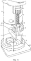
- Figs. 9-11 illustrate a macro-adjustment of the router base 100 relative to the router body 50.
- a user may wish to change the depth of the router base 100 by a relatively large amount.
- Using the fine adjustment method of Figs. 7 and 8 can be slow in such an instance.
- Macro-adjustment may instead be performed as shown in Figs. 9-11 .
- the lever 110 As shown in Fig. 9 , to begin the macro-adjustment process, the lever 110 must again first be released by rotating it in the direction A to loosen the base 100.
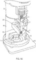
- the first end 131 of the lever 130 is depressed by a user as shown by arrow B.
- the lever 130 pivot about the rod 120 so that the second end 132 of the lever 130 including the threads 133 moves away from the threaded rod 71.
- the threads 133 are moved out of contact with the threaded rod 71 so that the lever 130 is no longer connected to the threaded rod 71.
- the user may move the base 100 up or down relative to the router body 50. This allows for quick macro adjustments.
- the user can release the adjustment lever 130 so that it moves back into contact with the threaded rod 71. The user can then, if desired, make micro adjustments using the adjustment knob 70.
- the rotatable latch lever 110 can be rotated back to the locked position shown in Figs. 1 , 2 and 5 . This pulls together the projections 105 and tightens the base 100 on the body 50 so that the base 100 is secured in place.
- the latch lever 110 and the adjustment lever 130 both are secured to the same rod 120. This allows for an efficient and compact configuration. Additionally, the latch lever 110 covers a portion of the adjustment lever 130 when the latch lever is in the closed position (e.g., Figs. 1 and 2 ).
Landscapes
- Life Sciences & Earth Sciences (AREA)
- Engineering & Computer Science (AREA)
- Mechanical Engineering (AREA)
- Wood Science & Technology (AREA)
- Forests & Forestry (AREA)
- Milling, Drilling, And Turning Of Wood (AREA)
Abstract
Description
- The present invention relates to power tools, especially routers. There are various existing power tools. It is desired to provide a power tool with an efficient depth adjustment mechanism.
- A first aspect of the present invention provides a router according to Claim 1 of the appended claims.
- Preferred, and other optional, features of the invention are defined and described in the dependent claims.
- According to an aspect of an exemplary embodiment, there is a router. The router includes a router body; a motor housed in the router body; an output member drivable by the motor; and a router base adjustably connected to the router body. wherein the router base includes a mounting rod, a latching lever and an adjustment lever. The latching lever and the adjustment lever may both be mounted on the mounting rod.
- The latching lever may be rotatable about a first axis and the adjustment lever is rotatable about a second axis.
- The second axis may be transverse to the first axis.
- The first axis may be transverse to a longitudinal axis of the mounting rod.
- The second axis may be along the longitudinal axis of the rod.
- The router body may further include a threaded rod extending along an outer surface of the router body.
- The router body may further include an adjustment knob.
- The adjustment knob may be connected to the threaded rod and rotation of the adjustment knob causes the threaded rod to rotate.
- The adjustment lever may include adjustment lever threads configured to selectively engage the threaded rod.
- The adjustment lever may be biased in a direction of the adjustment lever threads engaging with the threaded rod.
- The latching lever may be rotatable from a closed position to an open position.
- When the latching lever is in the closed position the router base may be held in place on the router body.
- When the latching lever is in the open position the router base may be movable relative to the router body.
- When the latching lever is in the closed position it may cover a portion of the adjustment lever.
- The router base may further include a battery receptacle configured to receive a removable battery pack.
- According to another aspect of an exemplary embodiment, there is a router. The router includes a router body; a motor housed in the router body; an output member configured to hold a router bit, the output member being drivable by the motor; and a router base adjustably connected to the router body. The router base includes a latching lever and an adjustment lever. The latching lever is rotatable between a closed position in which the router base is held in place on the router body and an open position in which the router base is movable relative to the router body. The latching lever is transverse to the adjustment lever.
- The router base has an upper end and a lower end; the upper end of the router base engages the router body; the lower end of the router base is adjacent to a workpiece; the adjustment lever has a first end and a second end; the second end of the adjustment lever includes threads; and the first end of the adjustment lever is closer to the lower end of the router base than the second end of the adjustment lever is to the router base.
- The first end of the adjustment lever may be configured to be actuated by a user to rotate the adjustment lever.
- The second end of the adjustment lever may extend above a top of the upper end of the router base.
- The first end of the adjustment lever may be below the top of the upper end of the router base.
- The router base may further comprise a pair of tabs and a mounting rod extending through the pair of tabs.
- The adjustment lever may be mounted on the mounting rod.
- The latching lever may be mounted on the mounting rod.
- According to another aspect of an exemplary embodiment, there is a router including a router body; a motor housed in the router body; an output member configured to hold a router bit, the output member being drivable by the motor; and a router base adjustably connected to the router body. The router body includes a threaded rod extending along an outside of the router body. The router base includes a latching lever an adjustment lever. The latching lever is rotatable between a closed position in which the router base is held in place on the router body and an open position in which the router base is movable relative to the router body.
- The adjustment lever may include threads configured to selectively engage the threaded rod.
- The latching lever may partially cover the adjustment lever when the latching lever is in the closed position.
- It is to be understood that any feature, including any preferred or other optional feature, of any aspect or embodiment of the invention may be a feature, including a preferred or other optional feature, of any other aspect or embodiment of the invention.
- A preferred embodiment of the invention will now be described, by way of example, with reference to the accompanying drawings, of which:
-
Fig. 1 is a perspective view of an exemplary embodiment of a router; -
Fig 2 is front perspective view of the exemplary embodiment of the router; -
Fig. 3 is a perspective view of an exemplary embodiment of a router body; -
Fig. 4 is a side view of the exemplary embodiment of the router body with the housing partially removed; -
Fig. 5 is a perspective view of an exemplary embodiment of a router base; -
Fig. 6 is a close-up perspective view of an exemplary embodiment of a router base; -
Fig. 7 is a perspective view of the exemplary embodiment of the router; -
Fig. 8 is another perspective view of the exemplary embodiment of the router; -
Fig. 9 is another perspective view of the exemplary embodiment of the router; -
Fig. 10 is another perspective view of the exemplary embodiment of the router -
Fig. 11 is another perspective view of the exemplary embodiment of the router; and -
Fig. 12 is a perspective view of an exemplary embodiment of a battery pack. - An exemplary embodiment of a router according to the present application is shown in
Figs. 1-12 .Figs. 1 and2 illustrate arouter 10 including abody 50 assembled with anadjustable base 100.Fig. 1 is a perspective view of therouter 10 andFig. 2 is a front view of the router. -
Fig. 3 illustrates a perspective view of therouter body 50 without thebase 100.Fig. 4 illustrates therouter body 50 with the housing partially removed to show internal components.Fig. 5 illustrates thebase 100 alone. - As shown in
Figs. 1 and2 , therouter 10 includes arouter body 50 and anadjustable base 100 connected to therouter body 50. As shown inFigs. 1-4 , therouter body 50 includes a battery receptacle portion 55. The battery receptacle portion 55 is configured to receive the powertool battery pack 200 shown inFig. 12 . The powertool battery pack 200 may be a twenty-volt lithium-ion removable battery pack that is configured to power a variety of tools such as sanders, saws, drills, impact drivers and the like, in addition to therouter 10. As shown inFig. 1 , the battery receptacle portion 55 is at a top of therouter body 50. - The
router body 50 includes apower switch 60. Thepower switch 60 is used to activate and deactivate therouter 10. The router body also includes adepth adjustment knob 70. Thedepth adjustment knob 70 can be rotated by a user. Thedepth adjustment knob 70 is connected to a threadedrod 71 so that when a user rotates thedepth adjustment knob 70, the threadedrod 71 rotates along with thedepth adjustment knob 70. As shown inFig. 3 , for example, the threadedrod 71 extends vertically along the lower length of therouter body 50. - As also shown in
Fig. 3 , therouter body 50 includes anoutput member 75. The output is arouter chuck 75 that holds various router bits. Therouter chuck 75 rotates about a vertical axis when therouter 10 is activated so that the motor is activated and drives thechuck 75. Therouter body 50 also includes aspindle lock 76. Thespindle lock 76 can be depressed by a user so that thespindle lock 76 extends into the spindle on which thechuck 75 is mounted. That holds the spindle and chuck 75 in place so that a router bit can be removed or attached to thechuck 75. -
Fig. 4 is a side view of therouter body 50 with a housing shell removed. As shown inFig. 4 , the battery receptacle portion 55 includeselectrical connectors 56 for electrically connecting with thebattery pack 200. Wires 57 connect the components such as theelectrical connectors 56,motor 80,switch 60 androtatable dial 61. Thedial 61 is rotatable to adjust the speed of themotor 80, as can be done through a potentiometer. As shown inFig. 4 , therouter 10 includes amotor 80. When therouter 80 is activated, power is provided to themotor 80. The motor drivesspindle 77 on which thechuck 75 is mounted so as to rotatably drive thechuck 75 and any router bit held by thechuck 75. As shown inFig. 4 , afan 78 may be mounted on thespindle 77 in order to provide a cooling effect. As previously discussed, thespindle lock 76 may be pressed to engaged with thespindle 77 and prevent rotation of thespindle 77. Thespindle lock 76 is biased by a biasing member away from thespindle 77 and a user must depress thespindle lock 76 and overcome the biasing force to engage it with thespindle 77. The biasing member may be one or more springs. - The
adjustable base 100 is shown in various figures, includingFigs. 1 ,2 ,5 and6 . Theadjustable base 100 is configured to be selectively clamped onto therouter body 50. As shown, thebase 100 includes a cylindrical sleeve 101. At a bottom of the cylindrical sleeve 101, there is aring 102. Thering 102 is attached to afoot plate 103. Thefoot plate 103 can be placed on a workpiece, such as a piece of wood. Adjusting the position of the base 100 changes the depth of a cut performed by a router bit driven by theoutput member 75. - As shown in
Figs. 5 and6 , thebase 100 includes arotatable latch lever 110. The sleeve 101 has a pair of projections ortabs 105. Arod 120 extends through holes in theprojections 105. One end of the rod includes a vertical through hole and apin 125 extends through therod 120 and engages with thelever 110. Thelever 110 is rotatable about thepin 125. - A
macro-adjustment lever 130 is also mounted on therod 120. The macro-adjustment lever has afirst end 131 configured to be pressed by a user to rotate thelever 130. Thesecond end 132 of thelever 130 is selectively engaged with the threadedrod 71. As shown inFig. 6 , thesecond end 132 of thelever 130 includesthreads 133 for engaging with the threadedrod 71. A torsion spring 135 biases themacro-adjustment lever 130 in a direction of thethreads 133 at thesecond end 132 of thelever 130 into engagement with the threadedrod 71. A user may push on thefirst end 131 in order to rotate thelever 130 and dis-engage thethreads 133 from the threadedrod 71. Theadjustment lever 130 is transverse to the latchinglever 110. In the exemplary embodiment, theadjustment lever 130 is disposed vertically and rotates about a horizontal axis and the latchinglever 110 is disposed horizontally and rotates about a vertical axis. - As shown in
Fig. 6 , thebase 100 has an upper end 107. Thethreads 133 start slightly below the upper end 107 and extend slightly above the upper end 107. Therod 120 and its central axis is below the upper end 107. - Operation of the
base 100 and its adjustment mechanism will be described with respect toFigs. 7-11 .Figs. 7 and8 illustrate operation of micro or fine adjustment of thebase 100. As shown inFig. 7 , first, a user opens thelatch 110 by rotating it in the direction of the arrow A. Acamming surface 125 on thelatch 110 is moved away from thetab 105 so that thebase 100 is loosened on therouter body 50 so that the base is able to be moved up and down. As shown inFig. 8 , the user can then rotate thedepth adjustment knob 70 in either direction. As previously discussed, when thedepth adjustment knob 70 is rotated, the threadedrod 71 rotates along with theadjustment knob 70. The threadedrod 71 is engaged with thethreads 133 at thesecond end 132 of thelever 130. Because of the engagement of therod 71 with thethreads 133, when the threadedrod 71 is rotated, thebase 100 is translated up or down, depending upon the direction of rotation of thedepth adjustment knob 70. If thedepth adjustment knob 70 is rotated in a first direction, thelever 130, and thus thebase 100, is moved downwardly along the threadedrod 71. If thedepth adjustment knob 70 is rotated in the other/second direction, the base is moved upwardly along the threadedrod 71. The screw thread allows for fine or micro-adjustments to be made. That is, when thedepth adjustment knob 70 is rotated, the screw thread interaction causes relatively small or fine relative movements of therouter base 100 relative to therouter body 50. This allows a user to precisely adjust the depth. Once thebase 100 reaches the appropriate depth, the user can rotate thelever 110 back to the closed position shown inFigs. 1 ,2 and5 . This tightens the base 100 so that it is secured in place on therouter body 50. The thread pitch and the size of thedepth adjustment knob 70 can be varied to provide an appropriate level of fine adjustment. -
Figs. 9-11 illustrate a macro-adjustment of therouter base 100 relative to therouter body 50. In some instances, a user may wish to change the depth of therouter base 100 by a relatively large amount. Using the fine adjustment method ofFigs. 7 and8 can be slow in such an instance. Macro-adjustment may instead be performed as shown inFigs. 9-11 . As shown inFig. 9 , to begin the macro-adjustment process, thelever 110 must again first be released by rotating it in the direction A to loosen thebase 100. Next, as shown inFig. 10 , thefirst end 131 of thelever 130 is depressed by a user as shown by arrow B. That causes thelever 130 to pivot about therod 120 so that thesecond end 132 of thelever 130 including thethreads 133 moves away from the threadedrod 71. In particular, thethreads 133 are moved out of contact with the threadedrod 71 so that thelever 130 is no longer connected to the threadedrod 71. As shown inFig. 11 , the user may move the base 100 up or down relative to therouter body 50. This allows for quick macro adjustments. When the user believes thebase 100 is in the correct position or relatively correct position, the user can release theadjustment lever 130 so that it moves back into contact with the threadedrod 71. The user can then, if desired, make micro adjustments using theadjustment knob 70. Once thebase 100 is in the desired position, therotatable latch lever 110 can be rotated back to the locked position shown inFigs. 1 ,2 and5 . This pulls together theprojections 105 and tightens the base 100 on thebody 50 so that thebase 100 is secured in place. - As shown, the
latch lever 110 and theadjustment lever 130 both are secured to thesame rod 120. This allows for an efficient and compact configuration. Additionally, thelatch lever 110 covers a portion of theadjustment lever 130 when the latch lever is in the closed position (e.g.,Figs. 1 and2 ). - While the invention has been described by way of an exemplary embodiment, it is understood that the words which have been used herein are words of description. Although the description provided above provides detail for the purpose of illustration based on what is currently considered to be the most practical and preferred embodiments, it is to be understood that such detail is solely for that purpose and that the disclosure is not limited to the expressly disclosed embodiment, but, on the contrary, is intended to cover modifications and equivalent arrangements that are within the scope of the appended claims. It is to be understood that the present disclosure contemplates that, to the extent possible, one or more features of any embodiment can be combined or exchanged with one or more features of any other embodiment.
Claims (15)
- A router (10), comprising:a router body (50);a motor (80) housed in the router body (50);an output member (75) drivable by the motor (80); anda router base (100) adjustably connected to the router body (50);wherein the router base (100) includes a mounting rod (120), a latching lever (110) and an adjustment lever (130); andwherein the latching lever (110) and the adjustment lever (130) are both mounted on the mounting rod (120).
- The router (10) of claim 1, wherein the latching lever (110) is rotatable about a first axis and the adjustment lever (130) is rotatable about a second axis; and wherein the second axis is transverse to the first axis.
- The router (10) of claim 2, wherein the first axis is transverse to a longitudinal axis of the mounting rod (120).
- The router (10) of claim 2 or claim 3, wherein the second axis is along the longitudinal axis of the mounting rod (120).
- The router (10) of any preceding claim, wherein the router body further includes a threaded rod (71) extending along an outer surface of the router body (50).
- The router (10) of claim 5, wherein an adjustment knob (70) is connected to the threaded rod (71), and rotation of the adjustment knob (70) is configured to cause the threaded rod (71) to rotate.
- The router (10) of claim 6, wherein the adjustment knob (70) configured to facilitate fine or micro-adjustments of a position the router body (50) relative to the router base (100).
- The router (10) of any one of claims 5 to 7, wherein the adjustment lever (130) includes adjustment lever thread portions (133) configured to selectively engage the threaded rod (71).
- The router (10) of claim 8, wherein the adjustment lever (130) is biased in a direction of the adjustment lever thread portions (133) engaging with the threaded rod (71).
- The router (10) of claim 9, wherein the adjustment lever (130) may be pivoted about the mounting rod (120) such that the adjustment lever thread portions (133) are moved out of contact with the threaded rod (71), thereby allowing the router body (50) to be moved in macro-adjustments relative to the router base (100).
- The router (10) of any preceding claim, wherein the latching lever (110) is rotatable from a closed position to an open position; wherein when the latching lever (110) is in the closed position the router base (100) is held in place on the router body (50); and wherein when the latching lever (110) is in the open position the router base (100) is movable relative to the router body (50).
- The router (10) of claim 11, wherein the latching lever (110) includes a camming surface which, when the latching lever (110) is in the closed position causes the router base (100) to be tightly secured in place on the router body (50).
- The router (10) of claim 12, wherein when the latching lever (110) is in the open position the router base (100) is loosened on the router body (50).
- The router (10) of any one of claims 11 to 13, wherein when the latching lever (110) is in the closed position it covers a portion of the adjustment lever (130).
- The router (10) of any preceding claim, wherein the router base (100) further comprises a battery receptacle (55) configured to receive a removable battery pack (200).
Applications Claiming Priority (1)
| Application Number | Priority Date | Filing Date | Title |
|---|---|---|---|
| US17/344,347 US11648704B2 (en) | 2021-06-10 | 2021-06-10 | Power tool router |
Publications (2)
| Publication Number | Publication Date |
|---|---|
| EP4101612A1 true EP4101612A1 (en) | 2022-12-14 |
| EP4101612B1 EP4101612B1 (en) | 2025-09-24 |
Family
ID=82308516
Family Applications (1)
| Application Number | Title | Priority Date | Filing Date |
|---|---|---|---|
| EP22177755.0A Active EP4101612B1 (en) | 2021-06-10 | 2022-06-08 | Router power tool |
Country Status (2)
| Country | Link |
|---|---|
| US (2) | US11648704B2 (en) |
| EP (1) | EP4101612B1 (en) |
Families Citing this family (3)
| Publication number | Priority date | Publication date | Assignee | Title |
|---|---|---|---|---|
| CN115922853A (en) * | 2021-10-04 | 2023-04-07 | 株式会社牧田 | Portable processing machine |
| CN217669927U (en) * | 2021-12-20 | 2022-10-28 | 创科无线普通合伙 | Keyway planer |
| US20240100732A1 (en) * | 2022-09-27 | 2024-03-28 | Milwaukee Electric Tool Corporation | Router |
Citations (4)
| Publication number | Priority date | Publication date | Assignee | Title |
|---|---|---|---|---|
| US5853273A (en) * | 1997-11-04 | 1998-12-29 | S-B Power Tool Company | Fixed-base router with V-block mounting |
| EP2163361A2 (en) * | 2008-09-11 | 2010-03-17 | Techtronic Power Tools Technology Limited | Router |
| US20100206432A1 (en) * | 2009-02-13 | 2010-08-19 | Credo Technology Corporation | Plunge Router Bearing |
| US20120045290A1 (en) * | 2010-08-19 | 2012-02-23 | Makita Corporation | Electrical power tools |
Family Cites Families (65)
| Publication number | Priority date | Publication date | Assignee | Title |
|---|---|---|---|---|
| US1370895A (en) | 1919-10-23 | 1921-03-08 | Evarts G Loomis | Shaper |
| US1565790A (en) | 1925-03-21 | 1925-12-15 | Ray L Carter | Portable routing machine |
| US1874232A (en) | 1927-11-15 | 1932-08-30 | Cincnnati Electrical Tool Comp | Routing device |
| US2855963A (en) | 1957-04-09 | 1958-10-14 | Black & Decker Mfg Co | Portable electric router |
| US2960126A (en) | 1959-07-15 | 1960-11-15 | Porter Cable Machine Co | Power operated cutting tool |
| US3443479A (en) | 1966-08-29 | 1969-05-13 | Mc Graw Edison Co | Depth adjustment for power tool |
| US3466973A (en) | 1968-01-08 | 1969-09-16 | Singer Co | Rack and pinion depth-of-cut adjusting mechanism for portable routers |
| US3767948A (en) | 1972-11-13 | 1973-10-23 | Singer Co | Concentric assembly for portable electric router |
| US3767876A (en) | 1972-11-17 | 1973-10-23 | Singer Co | Remote mechanical switch for actuating a power tool with particular microswitch locating means |
| US4239428A (en) | 1979-05-24 | 1980-12-16 | Berzina James A | Router adjustment attachment |
| US4272821A (en) | 1979-09-18 | 1981-06-09 | Black & Decker Inc. | Digital blade adjustment read-out for a portable power tool |
| US4319860A (en) | 1980-02-29 | 1982-03-16 | Black & Decker Inc. | Plunge type router |
| EP0052994A3 (en) | 1980-11-24 | 1983-08-17 | Black & Decker Inc. | Improvements in or relating to setting mechanisms especially for tools for carrying out routing and like operations |
| DE3314419C2 (en) | 1983-04-21 | 1985-09-12 | Festo-Maschinenfabrik Gottlieb Stoll, 7300 Esslingen | Router with dust extraction |
| US4652191A (en) | 1986-02-04 | 1987-03-24 | Lucien Bernier | Press router |
| US4770573A (en) | 1986-10-15 | 1988-09-13 | Ryobi Ltd. | Cutting depth adjusting mechanism of a router |
| US4938642A (en) | 1988-09-02 | 1990-07-03 | Hitachi Koki Company, Limited | Portable electric router |
| DE4008224A1 (en) | 1990-03-15 | 1991-09-19 | Metabowerke Kg | MILLING DEEP FINE ADJUSTING DEVICE OF A MILL |
| US5191921A (en) | 1991-10-18 | 1993-03-09 | Ryobi Motor Products Corp. | Adjustable depth of cut stop mechanism for a plunge type router |
| US5207253A (en) | 1992-03-20 | 1993-05-04 | Ryobi Motor Products, Corp | Plunge router |
| US5320463A (en) | 1993-05-24 | 1994-06-14 | Ryobi Motor Products Corp. | Depth stop for a plunge router |
| US5694992A (en) | 1996-12-26 | 1997-12-09 | Ryobi North America | Combination router |
| US5853274A (en) | 1997-11-04 | 1998-12-29 | S-B Power Tool Company | Vertical adjustment mechanism for fixed-base router |
| JP2000025007A (en) | 1998-07-07 | 2000-01-25 | Ryobi Ltd | Bite depth regulation mechanism for trimmer |
| US6261036B1 (en) | 1998-11-16 | 2001-07-17 | Porter-Cable Corporation | Plunge router locking system |
| US6318936B1 (en) | 2000-06-13 | 2001-11-20 | Mcfarlin, Jr. Robert E. | Plunge router adjustment mechanism and method |
| US6368033B2 (en) | 2000-06-26 | 2002-04-09 | Steven Howell Souders | Right-angle plunge router |
| US6443676B1 (en) | 2000-07-11 | 2002-09-03 | Roto Zip Tool Corporation | Automatic locking depth guide for cutting tools and the like |
| US6488455B1 (en) | 2000-07-28 | 2002-12-03 | S-B Power Tool Company | Plunge base router |
| US8087437B2 (en) | 2000-08-11 | 2012-01-03 | Techtronic Power Tools Technology Limited | Router |
| EP1238767B1 (en) | 2000-08-11 | 2006-10-18 | Milwaukee Electric Tool Corporation | Router |
| JP4489984B2 (en) | 2001-02-13 | 2010-06-23 | 株式会社マキタ | Trimmer |
| US6474378B1 (en) | 2001-05-07 | 2002-11-05 | S-B Power Tool Company | Plunge router having electronic depth adjustment |
| US6558090B2 (en) * | 2001-06-15 | 2003-05-06 | Porter-Cable/Delta | Cordless router |
| CN100526034C (en) | 2002-08-21 | 2009-08-12 | 密尔沃基电动工具公司 | Router |
| US6726414B2 (en) | 2002-09-17 | 2004-04-27 | One World Technologies, Limited | Depth adjustment for a fixed base router |
| US7334614B2 (en) | 2002-10-15 | 2008-02-26 | Black & Decker Inc. | Depth adjustment mechanism |
| US6986369B1 (en) | 2002-11-12 | 2006-01-17 | Porter-Cable Corporation | Router height adjustment apparatus |
| CA2454900C (en) | 2003-01-08 | 2011-12-13 | Credo Technology Corporation | Attachment for power tool |
| US7854054B2 (en) | 2003-01-08 | 2010-12-21 | Robert Bosch Tool Corporation | Attachment for power tool |
| US7275900B1 (en) | 2003-07-25 | 2007-10-02 | Black & Decker Inc. | Router elevating mechanism |
| US6896451B2 (en) | 2003-10-14 | 2005-05-24 | Credo Technology Corporation | Depth rod adjustment mechanism for a plunge-type router |
| DE10359420A1 (en) | 2003-12-18 | 2005-07-28 | Robert Bosch Gmbh | Hand tool |
| DE102004033801A1 (en) | 2004-07-12 | 2006-02-16 | Robert Bosch Gmbh | Hand tool |
| JP2008073988A (en) | 2006-09-22 | 2008-04-03 | Ryobi Ltd | Notch depth adjusting mechanism for cutting tool |
| DE102006061235B4 (en) | 2006-12-22 | 2019-06-06 | Robert Bosch Gmbh | router |
| DE102006061241A1 (en) | 2006-12-22 | 2008-06-26 | Robert Bosch Gmbh | router |
| DE102006061238B4 (en) | 2006-12-22 | 2019-05-29 | Robert Bosch Gmbh | router |
| CN201009086Y (en) | 2007-02-08 | 2008-01-23 | 南京德朔实业有限公司 | A height-adjustable power tool |
| US7900661B2 (en) | 2007-08-20 | 2011-03-08 | Milwaukee Electric Tool Corporation | Plunge router and kit |
| US7900662B2 (en) * | 2007-12-07 | 2011-03-08 | Black & Decker Inc. | Power tool with base clamp |
| CN201361737Y (en) | 2008-12-11 | 2009-12-16 | 南京德朔实业有限公司 | Edge trimmer |
| US8033307B2 (en) | 2009-02-13 | 2011-10-11 | Robert Bosch Gmbh | Modular router with base power switch |
| JP2011073159A (en) | 2009-09-29 | 2011-04-14 | Makita Corp | Power tools |
| WO2011075879A1 (en) | 2009-12-21 | 2011-06-30 | Robert Bosch Tool Corporation | Power tool having depth adjustment mechanism |
| JP2011213096A (en) * | 2010-03-19 | 2011-10-27 | Makita Corp | Power tool |
| DE102012223908B4 (en) | 2012-12-20 | 2021-02-11 | Robert Bosch Gmbh | Hand machine tool with a support device |
| DE102012223910A1 (en) | 2012-12-20 | 2014-06-26 | Robert Bosch Gmbh | Hand-held power tool e.g. router has height adjustment device with adjusting shaft that is provided to set working height of power tool by displacement of power tool in hollow cylindrical carrier element along longitudinal axis |
| JP6162007B2 (en) | 2013-02-15 | 2017-07-12 | 株式会社マキタ | Cutting tool and grip |
| US9403221B2 (en) | 2013-03-14 | 2016-08-02 | Robert Bosch Gmbh | One handed plunge base for a router |
| DE102013211752A1 (en) | 2013-06-21 | 2014-12-24 | Robert Bosch Gmbh | Tool system with a hand-held machine tool |
| GB201600883D0 (en) | 2016-01-18 | 2016-03-02 | Power Box Ag | Improvements to router apparatus |
| JP6808454B2 (en) | 2016-11-17 | 2021-01-06 | 株式会社マキタ | Portable cutting machine for woodworking |
| WO2020232199A1 (en) | 2019-05-15 | 2020-11-19 | Milwaukee Electric Tool Corporation | Offset base for router |
| CN212042789U (en) * | 2019-05-15 | 2020-12-01 | 米沃奇电动工具公司 | router |
-
2021
- 2021-06-10 US US17/344,347 patent/US11648704B2/en active Active
-
2022
- 2022-06-08 EP EP22177755.0A patent/EP4101612B1/en active Active
-
2023
- 2023-04-10 US US18/297,961 patent/US12162180B2/en active Active
Patent Citations (4)
| Publication number | Priority date | Publication date | Assignee | Title |
|---|---|---|---|---|
| US5853273A (en) * | 1997-11-04 | 1998-12-29 | S-B Power Tool Company | Fixed-base router with V-block mounting |
| EP2163361A2 (en) * | 2008-09-11 | 2010-03-17 | Techtronic Power Tools Technology Limited | Router |
| US20100206432A1 (en) * | 2009-02-13 | 2010-08-19 | Credo Technology Corporation | Plunge Router Bearing |
| US20120045290A1 (en) * | 2010-08-19 | 2012-02-23 | Makita Corporation | Electrical power tools |
Also Published As
| Publication number | Publication date |
|---|---|
| US12162180B2 (en) | 2024-12-10 |
| US11648704B2 (en) | 2023-05-16 |
| US20220396000A1 (en) | 2022-12-15 |
| US20230241799A1 (en) | 2023-08-03 |
| EP4101612B1 (en) | 2025-09-24 |
Similar Documents
| Publication | Publication Date | Title |
|---|---|---|
| US12162180B2 (en) | Power tool | |
| US5998897A (en) | Router chuck mounting system | |
| US5988241A (en) | Ergonomic router handles | |
| US6182723B1 (en) | Switchable router brake system | |
| US6261036B1 (en) | Plunge router locking system | |
| US6113323A (en) | Plunge router sub-base alignment | |
| US6079915A (en) | Plunge router depth stop system | |
| US6065912A (en) | Router switching system | |
| CN102114555B (en) | Electric tool | |
| US7473058B2 (en) | Power tool with a cutting depth adjustment mechanism | |
| US4827996A (en) | Power tool for trimming laminate | |
| US8087437B2 (en) | Router | |
| US6139229A (en) | Plunge router fine depth adjustment system | |
| JP5410843B2 (en) | Cutting machine | |
| EP1311374A1 (en) | Electric power tool | |
| JP7420162B2 (en) | power tools | |
| EP2502720B1 (en) | Power tool | |
| JP2014042988A (en) | Cutting machine | |
| US6260460B1 (en) | Machining tools having adjustable fences | |
| US9144919B2 (en) | Power tool having depth adjustment mechanism | |
| EP1984153A1 (en) | Rotary power tool | |
| US20070180709A1 (en) | Circular saw with rotatable handle | |
| JP6274522B2 (en) | Cutting machine | |
| US12257735B2 (en) | Router including cutting depth locking and adjustment mechanism | |
| JP7572269B2 (en) | Benchtop cutting machine |
Legal Events
| Date | Code | Title | Description |
|---|---|---|---|
| PUAI | Public reference made under article 153(3) epc to a published international application that has entered the european phase |
Free format text: ORIGINAL CODE: 0009012 |
|
| STAA | Information on the status of an ep patent application or granted ep patent |
Free format text: STATUS: THE APPLICATION HAS BEEN PUBLISHED |
|
| AK | Designated contracting states |
Kind code of ref document: A1 Designated state(s): AL AT BE BG CH CY CZ DE DK EE ES FI FR GB GR HR HU IE IS IT LI LT LU LV MC MK MT NL NO PL PT RO RS SE SI SK SM TR |
|
| STAA | Information on the status of an ep patent application or granted ep patent |
Free format text: STATUS: REQUEST FOR EXAMINATION WAS MADE |
|
| 17P | Request for examination filed |
Effective date: 20230612 |
|
| RBV | Designated contracting states (corrected) |
Designated state(s): AL AT BE BG CH CY CZ DE DK EE ES FI FR GB GR HR HU IE IS IT LI LT LU LV MC MK MT NL NO PL PT RO RS SE SI SK SM TR |
|
| GRAP | Despatch of communication of intention to grant a patent |
Free format text: ORIGINAL CODE: EPIDOSNIGR1 |
|
| STAA | Information on the status of an ep patent application or granted ep patent |
Free format text: STATUS: GRANT OF PATENT IS INTENDED |
|
| INTG | Intention to grant announced |
Effective date: 20241010 |
|
| GRAJ | Information related to disapproval of communication of intention to grant by the applicant or resumption of examination proceedings by the epo deleted |
Free format text: ORIGINAL CODE: EPIDOSDIGR1 |
|
| STAA | Information on the status of an ep patent application or granted ep patent |
Free format text: STATUS: REQUEST FOR EXAMINATION WAS MADE |
|
| INTC | Intention to grant announced (deleted) | ||
| GRAP | Despatch of communication of intention to grant a patent |
Free format text: ORIGINAL CODE: EPIDOSNIGR1 |
|
| STAA | Information on the status of an ep patent application or granted ep patent |
Free format text: STATUS: GRANT OF PATENT IS INTENDED |
|
| INTG | Intention to grant announced |
Effective date: 20250414 |
|
| P01 | Opt-out of the competence of the unified patent court (upc) registered |
Free format text: CASE NUMBER: APP_21099/2025 Effective date: 20250505 |
|
| GRAS | Grant fee paid |
Free format text: ORIGINAL CODE: EPIDOSNIGR3 |
|
| GRAA | (expected) grant |
Free format text: ORIGINAL CODE: 0009210 |
|
| STAA | Information on the status of an ep patent application or granted ep patent |
Free format text: STATUS: THE PATENT HAS BEEN GRANTED |
|
| AK | Designated contracting states |
Kind code of ref document: B1 Designated state(s): AL AT BE BG CH CY CZ DE DK EE ES FI FR GB GR HR HU IE IS IT LI LT LU LV MC MK MT NL NO PL PT RO RS SE SI SK SM TR |
|
| REG | Reference to a national code |
Ref country code: GB Ref legal event code: FG4D |
|
| REG | Reference to a national code |
Ref country code: CH Ref legal event code: EP |
|
| REG | Reference to a national code |
Ref country code: DE Ref legal event code: R096 Ref document number: 602022021838 Country of ref document: DE |
|
| REG | Reference to a national code |
Ref country code: IE Ref legal event code: FG4D |
|
| PG25 | Lapsed in a contracting state [announced via postgrant information from national office to epo] |
Ref country code: NO Free format text: LAPSE BECAUSE OF FAILURE TO SUBMIT A TRANSLATION OF THE DESCRIPTION OR TO PAY THE FEE WITHIN THE PRESCRIBED TIME-LIMIT Effective date: 20251224 |
|
| REG | Reference to a national code |
Ref country code: LT Ref legal event code: MG9D |
|
| PG25 | Lapsed in a contracting state [announced via postgrant information from national office to epo] |
Ref country code: FI Free format text: LAPSE BECAUSE OF FAILURE TO SUBMIT A TRANSLATION OF THE DESCRIPTION OR TO PAY THE FEE WITHIN THE PRESCRIBED TIME-LIMIT Effective date: 20250924 |
|
| PG25 | Lapsed in a contracting state [announced via postgrant information from national office to epo] |
Ref country code: HR Free format text: LAPSE BECAUSE OF FAILURE TO SUBMIT A TRANSLATION OF THE DESCRIPTION OR TO PAY THE FEE WITHIN THE PRESCRIBED TIME-LIMIT Effective date: 20250924 |
|
| PG25 | Lapsed in a contracting state [announced via postgrant information from national office to epo] |
Ref country code: GR Free format text: LAPSE BECAUSE OF FAILURE TO SUBMIT A TRANSLATION OF THE DESCRIPTION OR TO PAY THE FEE WITHIN THE PRESCRIBED TIME-LIMIT Effective date: 20251225 |
|
| PG25 | Lapsed in a contracting state [announced via postgrant information from national office to epo] |
Ref country code: SE Free format text: LAPSE BECAUSE OF FAILURE TO SUBMIT A TRANSLATION OF THE DESCRIPTION OR TO PAY THE FEE WITHIN THE PRESCRIBED TIME-LIMIT Effective date: 20250924 |
|
| PG25 | Lapsed in a contracting state [announced via postgrant information from national office to epo] |
Ref country code: LV Free format text: LAPSE BECAUSE OF FAILURE TO SUBMIT A TRANSLATION OF THE DESCRIPTION OR TO PAY THE FEE WITHIN THE PRESCRIBED TIME-LIMIT Effective date: 20250924 |
|
| PG25 | Lapsed in a contracting state [announced via postgrant information from national office to epo] |
Ref country code: BG Free format text: LAPSE BECAUSE OF FAILURE TO SUBMIT A TRANSLATION OF THE DESCRIPTION OR TO PAY THE FEE WITHIN THE PRESCRIBED TIME-LIMIT Effective date: 20250924 |
|
| PG25 | Lapsed in a contracting state [announced via postgrant information from national office to epo] |
Ref country code: RS Free format text: LAPSE BECAUSE OF FAILURE TO SUBMIT A TRANSLATION OF THE DESCRIPTION OR TO PAY THE FEE WITHIN THE PRESCRIBED TIME-LIMIT Effective date: 20251224 |
|
| REG | Reference to a national code |
Ref country code: NL Ref legal event code: MP Effective date: 20250924 |
|
| PG25 | Lapsed in a contracting state [announced via postgrant information from national office to epo] |
Ref country code: NL Free format text: LAPSE BECAUSE OF FAILURE TO SUBMIT A TRANSLATION OF THE DESCRIPTION OR TO PAY THE FEE WITHIN THE PRESCRIBED TIME-LIMIT Effective date: 20250924 |
|
| REG | Reference to a national code |
Ref country code: AT Ref legal event code: MK05 Ref document number: 1840064 Country of ref document: AT Kind code of ref document: T Effective date: 20250924 |
|
| PG25 | Lapsed in a contracting state [announced via postgrant information from national office to epo] |
Ref country code: SM Free format text: LAPSE BECAUSE OF FAILURE TO SUBMIT A TRANSLATION OF THE DESCRIPTION OR TO PAY THE FEE WITHIN THE PRESCRIBED TIME-LIMIT Effective date: 20250924 |
|
| PG25 | Lapsed in a contracting state [announced via postgrant information from national office to epo] |
Ref country code: ES Free format text: LAPSE BECAUSE OF FAILURE TO SUBMIT A TRANSLATION OF THE DESCRIPTION OR TO PAY THE FEE WITHIN THE PRESCRIBED TIME-LIMIT Effective date: 20250924 |
|
| PG25 | Lapsed in a contracting state [announced via postgrant information from national office to epo] |
Ref country code: AT Free format text: LAPSE BECAUSE OF FAILURE TO SUBMIT A TRANSLATION OF THE DESCRIPTION OR TO PAY THE FEE WITHIN THE PRESCRIBED TIME-LIMIT Effective date: 20250924 |
|
| PG25 | Lapsed in a contracting state [announced via postgrant information from national office to epo] |
Ref country code: IT Free format text: LAPSE BECAUSE OF FAILURE TO SUBMIT A TRANSLATION OF THE DESCRIPTION OR TO PAY THE FEE WITHIN THE PRESCRIBED TIME-LIMIT Effective date: 20250924 |
|
| PG25 | Lapsed in a contracting state [announced via postgrant information from national office to epo] |
Ref country code: IS Free format text: LAPSE BECAUSE OF FAILURE TO SUBMIT A TRANSLATION OF THE DESCRIPTION OR TO PAY THE FEE WITHIN THE PRESCRIBED TIME-LIMIT Effective date: 20260124 |
|
| PG25 | Lapsed in a contracting state [announced via postgrant information from national office to epo] |
Ref country code: PT Free format text: LAPSE BECAUSE OF FAILURE TO SUBMIT A TRANSLATION OF THE DESCRIPTION OR TO PAY THE FEE WITHIN THE PRESCRIBED TIME-LIMIT Effective date: 20260126 Ref country code: CZ Free format text: LAPSE BECAUSE OF FAILURE TO SUBMIT A TRANSLATION OF THE DESCRIPTION OR TO PAY THE FEE WITHIN THE PRESCRIBED TIME-LIMIT Effective date: 20250924 |
|
| PG25 | Lapsed in a contracting state [announced via postgrant information from national office to epo] |
Ref country code: PL Free format text: LAPSE BECAUSE OF FAILURE TO SUBMIT A TRANSLATION OF THE DESCRIPTION OR TO PAY THE FEE WITHIN THE PRESCRIBED TIME-LIMIT Effective date: 20250924 |
|
| PG25 | Lapsed in a contracting state [announced via postgrant information from national office to epo] |
Ref country code: SK Free format text: LAPSE BECAUSE OF FAILURE TO SUBMIT A TRANSLATION OF THE DESCRIPTION OR TO PAY THE FEE WITHIN THE PRESCRIBED TIME-LIMIT Effective date: 20250924 Ref country code: EE Free format text: LAPSE BECAUSE OF FAILURE TO SUBMIT A TRANSLATION OF THE DESCRIPTION OR TO PAY THE FEE WITHIN THE PRESCRIBED TIME-LIMIT Effective date: 20250924 |