EP4101540B1 - Transporting packaging units - Google Patents
Transporting packaging units Download PDFInfo
- Publication number
- EP4101540B1 EP4101540B1 EP22174018.6A EP22174018A EP4101540B1 EP 4101540 B1 EP4101540 B1 EP 4101540B1 EP 22174018 A EP22174018 A EP 22174018A EP 4101540 B1 EP4101540 B1 EP 4101540B1
- Authority
- EP
- European Patent Office
- Prior art keywords
- transport assembly
- apertures
- sleeves
- bottom opening
- perimeter
- Prior art date
- Legal status (The legal status is an assumption and is not a legal conclusion. Google has not performed a legal analysis and makes no representation as to the accuracy of the status listed.)
- Active
Links
Images







Classifications
-
- B—PERFORMING OPERATIONS; TRANSPORTING
- B65—CONVEYING; PACKING; STORING; HANDLING THIN OR FILAMENTARY MATERIAL
- B65D—CONTAINERS FOR STORAGE OR TRANSPORT OF ARTICLES OR MATERIALS, e.g. BAGS, BARRELS, BOTTLES, BOXES, CANS, CARTONS, CRATES, DRUMS, JARS, TANKS, HOPPERS, FORWARDING CONTAINERS; ACCESSORIES, CLOSURES, OR FITTINGS THEREFOR; PACKAGING ELEMENTS; PACKAGES
- B65D25/00—Details of other kinds or types of rigid or semi-rigid containers
- B65D25/02—Internal fittings
- B65D25/10—Devices to locate articles in containers
- B65D25/108—Devices, e.g. plates, presenting apertures through which the articles project
-
- B—PERFORMING OPERATIONS; TRANSPORTING
- B01—PHYSICAL OR CHEMICAL PROCESSES OR APPARATUS IN GENERAL
- B01L—CHEMICAL OR PHYSICAL LABORATORY APPARATUS FOR GENERAL USE
- B01L9/00—Supporting devices; Holding devices
- B01L9/06—Test-tube stands; Test-tube holders
-
- B—PERFORMING OPERATIONS; TRANSPORTING
- B65—CONVEYING; PACKING; STORING; HANDLING THIN OR FILAMENTARY MATERIAL
- B65D—CONTAINERS FOR STORAGE OR TRANSPORT OF ARTICLES OR MATERIALS, e.g. BAGS, BARRELS, BOTTLES, BOXES, CANS, CARTONS, CRATES, DRUMS, JARS, TANKS, HOPPERS, FORWARDING CONTAINERS; ACCESSORIES, CLOSURES, OR FITTINGS THEREFOR; PACKAGING ELEMENTS; PACKAGES
- B65D25/00—Details of other kinds or types of rigid or semi-rigid containers
- B65D25/02—Internal fittings
-
- B—PERFORMING OPERATIONS; TRANSPORTING
- B65—CONVEYING; PACKING; STORING; HANDLING THIN OR FILAMENTARY MATERIAL
- B65D—CONTAINERS FOR STORAGE OR TRANSPORT OF ARTICLES OR MATERIALS, e.g. BAGS, BARRELS, BOTTLES, BOXES, CANS, CARTONS, CRATES, DRUMS, JARS, TANKS, HOPPERS, FORWARDING CONTAINERS; ACCESSORIES, CLOSURES, OR FITTINGS THEREFOR; PACKAGING ELEMENTS; PACKAGES
- B65D71/00—Bundles of articles held together by packaging elements for convenience of storage or transport, e.g. portable segregating carrier for plural receptacles such as beer cans or pop bottles; Bales of material
- B65D71/70—Trays provided with projections or recesses in order to assemble multiple articles, e.g. intermediate elements for stacking
-
- B—PERFORMING OPERATIONS; TRANSPORTING
- B65—CONVEYING; PACKING; STORING; HANDLING THIN OR FILAMENTARY MATERIAL
- B65D—CONTAINERS FOR STORAGE OR TRANSPORT OF ARTICLES OR MATERIALS, e.g. BAGS, BARRELS, BOTTLES, BOXES, CANS, CARTONS, CRATES, DRUMS, JARS, TANKS, HOPPERS, FORWARDING CONTAINERS; ACCESSORIES, CLOSURES, OR FITTINGS THEREFOR; PACKAGING ELEMENTS; PACKAGES
- B65D85/00—Containers, packaging elements or packages, specially adapted for particular articles or materials
- B65D85/30—Containers, packaging elements or packages, specially adapted for particular articles or materials for articles particularly sensitive to damage by shock or pressure
- B65D85/302—Containers, packaging elements or packages, specially adapted for particular articles or materials for articles particularly sensitive to damage by shock or pressure for carboys
-
- B—PERFORMING OPERATIONS; TRANSPORTING
- B01—PHYSICAL OR CHEMICAL PROCESSES OR APPARATUS IN GENERAL
- B01L—CHEMICAL OR PHYSICAL LABORATORY APPARATUS FOR GENERAL USE
- B01L2300/00—Additional constructional details
- B01L2300/04—Closures and closing means
- B01L2300/041—Connecting closures to device or container
- B01L2300/045—Connecting closures to device or container whereby the whole cover is slidable
Definitions
- WO 2018/175985 A1 describes a cover assembly that may include a tray assembly frame, a first cover supported by the tray assembly frame, the first cover extending in a first plane and defining one or more first openings; a second cover supported by the tray assembly frame, the second cover extending in a second plane and defining one or more second openings, wherein the first and second planes are different planes, and wherein the second cover is disposed above the first cover.
- the upper part can include one or more upper guide surfaces and the lower part can include one or more lower guide surfaces.
- Each upper guide surface can be configured for sliding engagement with a corresponding lower guide surface as the upper part and lower part move between the closed configuration and the open configuration.
- One of the one or more upper guide surfaces and lower guide surfaces can extend along an outer edge of the transport assembly, for example.
- the plurality of sleeves and apertures can be arranged in one or more respective rows, and one of the one or more upper guide surfaces and lower guide surfaces extend between two adjacent rows of corresponding sleeves and apertures.
- the apertures 24 are formed with one or more gaps 38.
- the gaps 38 may make the apertures 24 more flexible and facilitate movement of the vials 100 through the apertures 24.
- the apertures 24 can have the same size and shape as the bottom openings 20, which may allow the transport assembly 10 to receive a larger number of vials 100 given the same outer dimensions.
- the apertures 24 may be formed larger than the bottom openings 20 to provide a similar effect.
- Figures 7A and 7B schematically show a circular aperture 24 that is larger than a hexagonal bottom opening 20. In the closed configuration ( Figure 7A ), the aperture 24 and the bottom opening 24 intersect to form an overlapping portion 40 that may support the vial 100 arranged in the sleeve 16 connected to the bottom opening 20.
- FIG 11 shows a plurality of vials 100 seated in a transport assembly 10'.
- the transport assembly 10' includes an upper part 12' and a lower part 14'.
- the lower part 14' includes a tab 30' that attaches the lower part 14' to the upper part 12'.
- the tab 30' is provided with hooks (not shown) that are designed to engage and translate along slots 60' that are formed in the flange 50' of the upper part 12'.
- the slots 60' may provide an upper guide surface that engages a corresponding lower guide surface provided by the hooks on the tab 30'.
- the hooks and the slot 30' may be easier to assemble than the hooks 32, 34.
- the slots 60' may be used to limit the relative movement between the upper part 12' and the lower part 14' along the Y-axis.
Landscapes
- Engineering & Computer Science (AREA)
- Mechanical Engineering (AREA)
- Health & Medical Sciences (AREA)
- Clinical Laboratory Science (AREA)
- Chemical & Material Sciences (AREA)
- Chemical Kinetics & Catalysis (AREA)
- Packages (AREA)
- Packaging Of Annular Or Rod-Shaped Articles, Wearing Apparel, Cassettes, Or The Like (AREA)
- Medical Preparation Storing Or Oral Administration Devices (AREA)
Description
- This disclosure relates to an assembly and method for transporting packaging units.
- In industrial contexts, products are generally transported and sold in packaging units. Packaging units can include vials, cartridges, ampoules, bottles, or pre-fillable syringes. In many industries, these different types of packaging units are collectively known as "primary packaging," i.e., the packaging that comes into direct contact with an end product. The end product may be a food product, a cosmetic product, or a pharmaceutical product. Primary packaging can undergo numerous manufacturing processes before being filled with the end product. During these processes, primary packaging is often processed in batches.
-
US 2014/216059 A1 describes a cold box having a cooling receptacle filled with a dry protective gas in which is accommodated a rack loaded with tube-shaped vessels. The cooling receptacle is covered by a displaceable lid which is associated with a lid part and which is preferably formed by an outer lid and a rotatable# inner lid integrated in the outer lid so that the cooling receptacle is completely covered in every position of the lid. At least one of the through-holes provided in the inner lid can be arranged over a respective tube-shaped vessel by a coordinated displacement of the outer lid and rotation of the inner lid so that the tube-shaped vessel located under the through-hole in alignment therewith can be filled with a sample through the through-hole by means of a commercially available pipette tip/dispensing needle of an automated pipetting device. -
WO 2018/175985 A1 describes a cover assembly that may include a tray assembly frame, a first cover supported by the tray assembly frame, the first cover extending in a first plane and defining one or more first openings; a second cover supported by the tray assembly frame, the second cover extending in a second plane and defining one or more second openings, wherein the first and second planes are different planes, and wherein the second cover is disposed above the first cover. The cover assembly may include one or more tray holders, each tray holder being configured to hold at least one tray in an upright orientation, wherein each tray holder is moveable between an open position and a closed position, the tray holders being accessible for loading or removing the trays in the open position, and the tray holders being positioned beneath the first and second covers in the closed position. -
EP 0 903 176 A2 describes that the simultaneous synthesis of diverse organic compounds is performed in stackable modules which are moveable among nesting sites located on work station platforms. The reactor module includes a block adapted to receive an array of tube-like reactor vessels. The vessels are sized to optionally accept porus polyethelyene mircocannisters with radio frequency transmitter tags. Each vessel has a bottom port connected to an outlet tube. A valve block located below the reactor vessels simultaneously controls discharge through the outlet tubes. The valve block includes plates with aligned, relatively moveable sets of rib surfaces which act through Teflon encapsulated silicone o-ring cord sections to simultaneously close rows of outlet tubes. By first utilizing reactor vessels in one set of 48 positions, out of the possible 52 reactor vessels positions in the reactor block, and then utilizing reactor vessels in the other set of 48 positions and shifting the relative position of the collection plate, a single reactor can be employed to discharge into all of the wells of a standard 96 well microtiter collection plate. The apparatus can be used to perform the entire synthesis or only the final cleavage step of a radio frequency tagged synthesis. - Aspects of the present disclosure aim to provide a transport assembly, as disclosed in claim 1, and method for transporting packaging units between various industrial processes, as disclosed in
claim 12. - The object of the present invention is achieved by a transport assembly and by a method according to the independent claims. Further advantageous developments of the present invention are set out in the dependent claims.
- According to the present invention, a transport assembly includes an upper part that comprises a plurality of sleeves, each sleeve extending along a sleeve axis between a top opening and a bottom opening, wherein the plurality of sleeves are arranged with their respective axes in parallel to one another, and a lower part that comprises a plate with a plurality of apertures that each extend through the plate. The upper part and the lower part can be coupled such that each bottom opening is arranged adjacent to one of the plurality of apertures, and the upper part and the lower part can be moved relative to one another between a closed configuration in which a perimeter of each bottom opening intersects a perimeter of a corresponding aperture at two or more points, and an open configuration in which the perimeter of each bottom opening is aligned with or is enclosed by the perimeter of a corresponding aperture. In other words, a center of each aperture coincides with the sleeve axis and an axis of the packaging unit disposed in the sleeve, respectively. In the context of this disclosure, "aligned with" can also mean superimposed or matched.
- The bottom openings and the apertures may have the same shape and, in some instances, have the same size. It is also possible for the apertures to be larger than the bottom openings.
- The upper part can include one or more upper guide surfaces and the lower part can include one or more lower guide surfaces. Each upper guide surface can be configured for sliding engagement with a corresponding lower guide surface as the upper part and lower part move between the closed configuration and the open configuration. One of the one or more upper guide surfaces and lower guide surfaces can extend along an outer edge of the transport assembly, for example. The plurality of sleeves and apertures can be arranged in one or more respective rows, and one of the one or more upper guide surfaces and lower guide surfaces extend between two adjacent rows of corresponding sleeves and apertures.
- The lower part can include a pair of projections arranged on opposite sides of the lower part and configured to abut a respective one of the plurality of sleeves.
- An outer edge of the upper part can include a recessed portion, and an outer edge of the lower part can include a tab. The recessed portion and the tab can be gripped to move the upper part and lower part between the closed configuration and the open configuration.
- The transport assembly can include a lock that engages when the upper part and lower part are in the closed configuration to prevent relative movement between the upper part and the lower part.
- The upper part can include a flange arranged adjacent to the top openings of the plurality of sleeves.
- According to the present invention, a method includes receiving an upper part that comprises a plurality of sleeves, each sleeve extending along a sleeve axis between a top opening and a bottom opening, wherein the plurality of sleeves are arranged with their respective axes in parallel to one another; receiving a lower part that comprises a plate with a plurality of apertures that each extend through the plate; coupling the upper part to the lower part such that each bottom opening is arranged adjacent to one of the plurality of apertures; moving the upper part and the lower part into a closed configuration in which a perimeter of each bottom opening intersects a perimeter of a corresponding aperture at two or more points; and loading a plurality of packaging units in respective sleeves of the upper part, wherein an opening of each packaging unit is arranged adjacent to the top opening of the sleeve, and a bottom of each packaging unit is arranged adjacent to the bottom opening of the sleeve and supported from below by the lower part.
- The method according to the present invention further includes moving the upper part and the lower part into an open configuration in which the perimeter of each bottom opening is aligned with or is enclosed by the perimeter of a corresponding aperture, and moving the bottom of each packaging unit through a respective bottom opening and aperture to rest the packaging unit on a flat surface.
- The method can include returning the upper part and the lower part into the closed configuration, such that the lower part is positioned between the bottom of each packaging unit and the flat surface.
- The method can include locking the upper part and the lower part in the closed configuration to prevent relative movement between the upper part and the lower part.
- These and other embodiments described herein may provide one or more of the following benefits. The transport assembly and method according to the present disclosure can be used to transport a plurality of packaging units at once. For example, the upper part can secure and separate the individual packaging units from one another. In the open position, the packaging units can be released from the transport assembly simultaneously. In some instances, the transport assembly can be removed to allow further processing of the packaging units. Simultaneous release may replace individual unloading of the packaging units by hand or by machine. The released packaging units may also remain within the transport assembly in the open configuration, e.g., to facilitate thermal transfer between the bottoms of the packaging units and a lyophilization table or plate. After the lyophilization process is completed, the transport assembly may be returned to the closed configuration to simultaneously retrieve the packaging units for further transport.
- Certain embodiments will now be described, by way of example only, with reference to the accompanying drawings, in which:
-
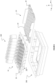
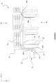
Figure 1 shows the components of a first transport assembly according to the present disclosure, a plurality of vials, and a transport container; -
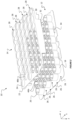
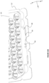
Figures 2 to 4 show the parts of the transport assembly ofFigure 1 from below; -
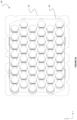
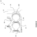
Figures 5 and6 show the parts ofFigure 1 in a closed and open configuration, respectively; -
Figure 7 shows various configurations of bottom openings and apertures; -
Figure 8 shows a partial cross-sectional view of the transport assembly ofFigures 1 to 6 ; -
Figure 9 shows a cross-sectional view of the transport assembly ofFigures 1 to 6 and8 in the closed configuration; -
Figure 10 shows an optional lock that may lock the transport assembly in the closed configuration; -
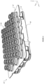
Figure 11 shows a second transport assembly according to the present disclosure; -
Figures 12 and13 show a third transport assembly according to the present disclosure; -
Figure 14 shows the transport assembly ofFigures 12 and13 in the closed and open configurations, respectively; and -
Figure 15 is a schematic overview of a method according to the present disclosure. - Like reference numbers and designations in the various drawings indicate like elements.
-
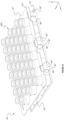
Figure 1 shows the components of atransport assembly 10 according to the present disclosure, a plurality ofpackaging units 100, and atransport container 200. Thepackaging units 100 can serve as primary packaging for various types of end products. Although the expression "primary packaging" can encompass vials, cartridges, ampoules, bottles, and syringes to name a few examples, the following description will refer to "vials" for all types of primary packaging. Thecontainer 200 can serve as "secondary packaging," i.e., packaging that groups, protects, and labels the primary packaging. - The
transport assembly 10 can be used to securely position thevials 100 within thecontainer 200 and includes anupper part 12 and alower part 14 that are configured to couple to one another. Theupper part 12 includes a plurality ofsleeves 16. Each sleeve extends along a sleeve axis between atop opening 18 and a bottom opening 20 (Figure 8 ). Referring to the coordinate axes shown inFigure 1 , the plurality ofsleeves 16 are arranged with their respective axes extending in parallel along the Z-axis. Thelower part 14 includes aplate 22 with a plurality ofapertures 24 that each extend through theplate 22 in the direction of the Z-axis. Theupper part 12 and thelower part 14 can be coupled such that eachbottom opening 20 is arranged adjacent to one of the plurality ofapertures 24 in thelower part 14. -
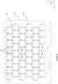
Figure 2 shows theupper part 12 and thelower part 14 from below. As illustrated, theupper part 12 includes an array ofsleeves 16 formed by sixrows 26 of eightsleeves 16 each. Thelower part 14 includes an array ofapertures 24 formed by sixrows 28 of eightapertures 24 each. Although the number ofsleeves 16 andapertures 24 may vary from what is shown, the respective arrays will generally have the same dimensions and arrangement. - The
upper part 12 and thelower part 14 can be coupled to one another. For example,Figure 2 shows the lower part as having twotabs 30 that extend along the Z-axis, towards theupper part 12. The end of eachtab 30 is provided with twohooks 32 that are designed to engage correspondinghooks 34 formed on theupper part 12.Figure 3 shows thehooks Figure 3 , thehooks lower parts -
Figure 4 shows theupper part 12 and thelower part 14 after they have been translated along the Y-axis to bring thehooks upper part 12 and thelower part 14 are coupled. In the coupled position, eachbottom opening 20 is arranged adjacent to one of the plurality ofapertures 24. From the coupled position shown inFigure 4 , theupper part 12 and thelower part 14 can be moved along the Y-axis relative to one another between a closed configuration shown inFigures 5A and5B and an open configuration shown inFigure 6A and6B . - An outer edge of the
upper part 12 can include one or more recessedportions 44, and an outer edge of thelower part 14 can include one ormore tabs 42. The recessedportions 44 andtabs 42 can be gripped on opposite sides of thetransport assembly 10 to move theupper part 12 andlower part 14 between the closed configuration and the open configuration. -
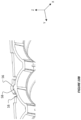
Figure 5A shows theupper part 12 and thelower part 14 from below in the closed configuration.Figure 5B is an enlarged partial view ofFigure 5B . In the closed configuration, a perimeter of eachbottom opening 20 intersects a correspondingaperture 24 at two or more points. InFigure 5B , thebottom openings 20 and theapertures 24 are arranged so closely that the perimeter of thebottom opening 20 intersects theaperture 24 at four points in total, as shown by the dashed lines 36. Due to the intersection, the sections of the plate inward of the dashedlines 36 overlap with thebottom opening 20. The overlapping portions support a bottom of the vial 100 (Figure 9 ). InFigures 1 to 5 , theapertures 24 are formed with one ormore gaps 38. In some instances, theapertures 24 may not includegaps 38, and eachbottom opening 20 may be overlapped by a single,continuous portion 40 of the plate 22 (Figure 7A to 7D ). - From the closed configuration shown in
Figures 5A and5B , thelower part 14 can be shifted to the left along the Y-axis and into the open configuration shown inFigures 6A and6B . In the open configuration, the perimeter of eachbottom opening 20 is aligned with or is enclosed by the perimeter of a correspondingaperture 24. In other words, a center of eachaperture 24 coincides with the sleeve axis and an axis of thevial 100, respectively. The alignment eliminates the overlapping sections that support the bottom of thevial 100. Thus, thevial 100 is free to pass through both thebottom opening 20 and theaperture 24. InFigures 6A and6B , thebottom openings 20 and theapertures 24 have substantially the same shape and size. In the context of this disclosure, "aligned with" can also mean superimposed or matched. - As described above, the
apertures 24 are formed with one ormore gaps 38. Thegaps 38 may make theapertures 24 more flexible and facilitate movement of thevials 100 through theapertures 24. Thus, theapertures 24 can have the same size and shape as thebottom openings 20, which may allow thetransport assembly 10 to receive a larger number ofvials 100 given the same outer dimensions. In some instances, theapertures 24 may be formed larger than thebottom openings 20 to provide a similar effect. For example,Figures 7A and 7B schematically show acircular aperture 24 that is larger than ahexagonal bottom opening 20. In the closed configuration (Figure 7A ), theaperture 24 and thebottom opening 24 intersect to form an overlappingportion 40 that may support thevial 100 arranged in thesleeve 16 connected to thebottom opening 20. In the open configuration (Figure 7B ), thelarger aperture 24 completely encloses thebottom opening 20, which allows thevial 100 to move through thebottom opening 20. The same applies toFigures 7C and 7D , which show ahexagonal aperture 24 and acircular bottom opening 20. -
Figure 8 is a partial cross-sectional view of thetransport assembly 10. To facilitate movement between the open and closed configurations, theupper part 12 can include one or more upper guide surfaces 46 and the lower part can include one or more lower guide surfaces 48. Each upper guide surface 46 is configured for sliding engagement with a corresponding lower guide surface 48 as theupper part 12 andlower part 14 move along the Y-axis, between the closed configuration and the open configuration shown, e.g., inFigures 4 to 6 . - For example, a first
upper guide surface 46a is designed to slide along a firstlower guide surface 48a. The first upper andlower guide surfaces transport assembly 10. More specifically, the firstupper guide surface 46a is formed on an underside of thehook 34, and the firstlower guide surface 48a is formed on an underside of thehook 32. In other words, thehooks upper part 12 to thelower part 14 and simultaneously provideguide surfaces lower parts Figures 11 and12 , this dual-purpose engagement between the upper andlower parts Figure 8 . - In instances in which the
sleeves 16 are arranged in one ormore sleeve rows 26 and theapertures 24 are arranged in one ormore aperture rows 28, the guide surfaces can include a secondupper guide surface 46b and a secondlower guide surface 48b that extend betweenadjacent rows sleeves 16 andapertures 24. When such guide surfaces are provided between each of theadjacent rows bottom openings 20 and theapertures 24 may be more easily attained in the closed configuration of thetransport assembly 10. Referring to the exploded view ofFigure 2 , the secondlower guide surface 48b can be formed on opposite sides of a rib that continuously extends along the Y-axis between twoadjacent aperture rows 28. The secondupper guide surface 46b can be formed by opposing pairs of pads that are designed to contact the respective sides of the rib that forms the secondlower guide surface 48b. -
Figure 8 also shows thetop openings 18 of the plurality ofsleeves 16 and aflange 50 of theupper part 12 that is arranged adjacent to the plurality oftop openings 18. Theflange 50 may be useful for handling thetransport assembly 10 and for seating thetransport assembly 10 inside the container 200 (Figure 1 ). -
Figure 9 is a cross-sectional view of thetransport assembly 10 taken in the X-Y plane in the closed configuration. In this view, the overlappingportion 40 between a corresponding bottom opening 20 andaperture 24 is visible. As described, the overlappingportion 40 supports the bottom surface of a vial 100 (not shown), so that thetransport assembly 10 can be used to transport thevial 100. -
Figure 9 also shows thetabs 42 for manipulating thelower part 14 in greater detail. As shown, thelower part 14 comprises two sets oftabs 42 on each end of thelower part 14. In some instances, thelower part 14 can include fewer or greater numbers oftabs 42 on each end. In addition to thetabs 42, each end of thelower part 14 includes aprojection 52 that is designed to come into contact with the peripheral surface of anadjacent sleeve 16. Theprojections 52 may ensure proper alignment of thebottom openings 20 and theapertures 24 in the closed configuration of thetransport assembly 10 and provide haptic feedback for the user. -
Figures 10A and10B show an optional feature of thetransport assembly 10 from below and above, respectively. Specifically, thetab 30 of thelower part 14 that forms thehook 32 is provided with aresilient tongue 54 that is configured to deform as theupper part 12 and thelower part 14 move relative to one another. An inner surface of theresilient tongue 54 is provided with anindentation 56 that is shape matched to aprojection 58 formed on an outer peripheral surface of one of thesleeves 16. As theupper part 12 and thelower part 14 are brought into the closed configuration shown inFigure 10A , theprojection 58 snaps into theindentation 56 to lock thetransport assembly 10 in the closed configuration. At the same time, the snap-fit engagement between theprojection 58 andindentation 56 and the indentation may provide both acoustic and haptic feedback that thetransport assembly 10 is in the closed configuration. The illustrated lock may provide additional stability when thetransport assembly 10 is used to lift a plurality of vials 100 (not shown). However, the engagement of the lock can be overcome to move thetransport assembly 10 into the open configuration to release thevials 100. - Referring now to
Figures 11 to 14 , various modifications of thetransport assembly 10 ofFigures 1 to 10 are shown. The modifications shown inFigures 11 to 14 can be combined or replaced with features from the transport assembly ofFigures 1 to 10 and vice versa. -
Figure 11 shows a plurality ofvials 100 seated in a transport assembly 10'. The transport assembly 10' includes an upper part 12' and a lower part 14'. As inFigures 1 to 10 , the lower part 14' includes a tab 30' that attaches the lower part 14' to the upper part 12'. However, instead ofhooks hooks -
Figure 12 shows a plurality ofvials 100 seated in atransport assembly 10". Thetransport assembly 10" includes anupper part 12" and alower part 14". Instead of the singlecontinuous tab 30, 30' shown inFigures 1 to 11 , thelower part 14" is attached to theupper part 12" by threeshorter tabs 30". The end of eachtab 30" comprises ahook 62" that protrudes through acorresponding slot 60" in theupper flange 50" of theupper part 12". -
Figure 13 shows theupper part 12" ofFigure 12 from below. As shown inFigure 13 , thebottom openings 20" of the plurality ofsleeves 16" do not necessarily have the same shape across the entireupper part 12". For example, afirst type 20a" ofbottom opening 20" has a substantially hexagonal shape. Asecond type 20b" ofbottom opening 20" has a five-sided shape with a mixture of straight and curved sidewalls. -
Figure 14A and14B show thetransport assembly 10" in the closed and open configurations, respectively. In thetransport assembly 10", thesleeves 16" include a plurality of supportingarms 64" that extend into a respective bottom opening 20" (Figure 13 ) and designed to support an outer surface of a vial 100 (Figure 14A ). As shown inFigure 14B , the supportingarms 64" are designed so as not to obstruct thevials 100 from moving through theapertures 24" in the open configuration. -
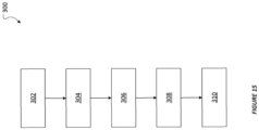
Figure 15 is a schematic overview of amethod 300 according to the present disclosure. For example, themethod 300 can be implemented using any of thetransport assemblies - The
method 300 includes receiving 302 an upper part that comprises a plurality of sleeves, each sleeve extending along a sleeve axis between a top opening and a bottom opening, wherein the plurality of sleeves are arranged with their respective axes in parallel to one another; receiving 304 a lower part that comprises a plate with a plurality of apertures that each extend through the plate; coupling 306 the upper part to the lower part such that each bottom opening is arranged adjacent to one of the plurality of apertures; moving 308 the upper part and the lower part into a closed configuration in which a perimeter of each bottom opening intersects a perimeter of a corresponding aperture at two or more points; and loading 310 a plurality of packaging units in respective sleeves of the upper part, wherein an opening of each container is arranged adjacent to the top opening of the sleeve, and a bottom of each container is arranged adjacent to the bottom opening of the sleeve and supported from below by the lower part. Such a method may arrange the plurality of packaging units (e.g., vials) so that they are ready for transport. For example, the vials and the transport assembly can be placed in a secondary container, such as thecontainer 200 shown inFigure 1 . - The
method 300 can include moving the upper part and the lower part into an open configuration in which the perimeter of each bottom opening is aligned with or is enclosed by the perimeter of a corresponding aperture, and moving the bottom of each container through a respective bottom opening and aperture to rest the container on a flat surface. In this way, a plurality of packaging units can be unloaded from the transport assembly at once. - Once the transport assembly is in the open configuration, the transport assembly can be lifted away from the packaging units, which can then be retrieved for further processing steps. In some cases, the packaging units may remain in the transport assembly in this open configuration. For example, the open configuration may be used to expose the bottom of the packaging units to a lyophilization table and improve heat transfer between the lyophilization equipment and the packaging units.
- The
method 300 can include returning the upper part and the lower part into the closed configuration, such that the lower part is positioned between the bottom of each container and the flat surface. For example, if the packaging units have been placed into contact with a lyophilization table, moving the transport assembly back to the closed configuration may be used to simultaneously "pick up" the plurality of packaging units for further transport and processing. Themethod 300 can include locking the upper part and the lower part in the closed configuration to prevent relative movement between the upper part and the lower part.
Claims (14)
- A transport assembly (10, 10', 10") comprising:an upper part (12, 12', 12") that comprises a plurality of sleeves (16, 16"), each sleeve (16, 16") extending along a sleeve axis between a top opening (18) and a bottom opening (20, 20"), wherein the plurality of sleeves (16, 16") are arranged with their respective axes in parallel to one another; anda lower part (14, 14', 14") that comprises a plate (22) with a plurality of apertures (24, 24") that each extend through the plate (22),wherein the upper part (12, 12', 12") and the lower part (14, 14', 14") can be coupled such that each bottom opening (20, 20") is arranged adjacent to one of the plurality of apertures (24, 24"), and the upper part (12, 12', 12") and the lower part (14, 14', 14") can be moved relative to one another betweena closed configuration in which a perimeter of each bottom opening (20, 20") intersects a perimeter of a corresponding aperture (24, 24") at two or more points andan open configuration in which the perimeter of each bottom opening (20, 20") is aligned with or is enclosed by the perimeter of a corresponding aperture (24, 24").
- The transport assembly (10, 10', 10") according to claim 1, wherein the bottom openings (20, 20") and the apertures (24, 24") have the same shape.
- The transport assembly (10, 10', 10") according to claim 2, wherein the bottom openings (20, 20") and the apertures (24, 24") are the same size.
- The transport assembly (10, 10', 10") according to claim 2, wherein the apertures (24, 24") are larger than the bottom openings (20, 20").
- The transport assembly (10, 10', 10") according to any one of claims 1 to 4,wherein the upper part (12, 12', 12") comprises one or more upper guide surfaces (46a, 46b) and the lower part (14, 14', 14") comprises one or more lower guide surfaces (48a, 48b),wherein each upper guide surface (46a, 46b) is configured for sliding engagement with a corresponding lower guide surface (48a, 48b) as the upper part (12, 12', 12") and lower part (14, 14', 14") move between the closed configuration and the open configuration.
- The transport assembly (10, 10', 10") according to claim 5, wherein one of the one or more upper guide surfaces (46a, 46b) and lower guide surfaces (48a, 48b) extend along an outer edge of the transport assembly (10, 10', 10").
- The transport assembly (10, 10', 10") according to claim 5 or 6,wherein the plurality of sleeves (16, 16") are arranged in one or more rows (26),wherein the plurality of apertures (24, 24") are arranged in one or more rows (28), andwherein one of the one or more upper guide surfaces (46a, 46b) and lower guide surfaces (48a, 48b) extend between two adjacent rows (26, 28)) of corresponding sleeves (16, 16") and apertures (24, 24").
- The transport assembly (10, 10', 10") according to any one of claims 1 to 7, wherein the lower part (14, 14', 14") comprises a pair of projections (52) arranged on opposite sides of the lower part (14, 14', 14") and configured to abut a respective one of the plurality of sleeves (16, 16").
- The transport assembly (10, 10', 10") according to any one of claims 1 to 8, wherein an outer edge of the upper part (12, 12', 12") comprises a recessed portion (44), and wherein an outer edge of the lower part (14, 14', 14") comprises a tab (42), wherein the recessed portion (44) and the tab (42) can be gripped to move the upper part (12, 12', 12") and lower part (14, 14', 14") between the closed configuration and the open configuration.
- The transport assembly (10, 10', 10") according to any one of claims 1 to 9, further comprising a lock (56, 58) that engages when the upper part (12, 12', 12") and lower part (14, 14', 14") are in the closed configuration to prevent relative movement between the upper part (12, 12', 12") and the lower part (14, 14', 14").
- The transport assembly (10, 10', 10") according to any one of claims 1 to 10, wherein the upper part (12, 12', 12") comprises a flange (50, 50', 50") arranged adjacent to the top openings (18) of the plurality of sleeves (16, 16").
- A method for transporting packaging units (100), comprising:receiving an upper part (12, 12', 12") that comprises a plurality of sleeves (16, 16"), each sleeve (16, 16") extending along a sleeve axis between a top opening (18) and a bottom opening (20, 20"), wherein the plurality of sleeves (16, 16") are arranged with their respective axes in parallel to one another;receiving a lower part (14, 14', 14") that comprises a plate (22) with a plurality of apertures (24, 24") that each extend through the plate (22);coupling the upper part (12, 12', 12") to the lower part (14, 14', 14") such that each bottom opening (20, 20") is arranged adjacent to one of the plurality of apertures (24, 24");moving the upper part (12, 12', 12") and the lower part (14, 14', 14") into a closed configuration in which a perimeter of each bottom opening (20, 20") intersects a perimeter of a corresponding aperture (24, 24") at two or more points;loading a plurality of packaging units (100) in respective sleeves (16, 16") of the upper part (12, 12', 12"), wherein an opening of each packaging unit (100) is arranged adjacent to the top opening (18) of the sleeve (16, 16"), and a bottom of each packaging unit (100) is arranged adjacent to the bottom opening (20, 20") of the sleeve (16, 16") and supported from below by the lower part (14, 14', 14");moving the upper part (12, 12', 12") and the lower part (14, 14', 14") into an open configuration in which the perimeter of each bottom opening (20, 20") is aligned with or is enclosed by the perimeter of a corresponding aperture (24, 24"); andmoving the bottom of each packaging unit (100) through a respective bottom opening (20, 20") and aperture (24, 24") to rest the packaging units (100) on a flat surface.
- The method according to claim 12, further comprising:
returning the upper part (12, 12', 12") and the lower part (14, 14', 14") into the closed configuration, such that the lower part (14, 14', 14") is positioned between the bottom of each packaging unit (100) and the flat surface. - The method according to any one of claims 12 to 13, further comprising:
locking the upper part (12, 12', 12") and the lower part (14, 14', 14") in the closed configuration to prevent relative movement between the upper part (12, 12', 12") and the lower part (14, 14', 14").
Applications Claiming Priority (1)
| Application Number | Priority Date | Filing Date | Title |
|---|---|---|---|
| US202163190082P | 2021-05-18 | 2021-05-18 |
Publications (2)
| Publication Number | Publication Date |
|---|---|
| EP4101540A1 EP4101540A1 (en) | 2022-12-14 |
| EP4101540B1 true EP4101540B1 (en) | 2023-11-29 |
Family
ID=81748652
Family Applications (1)
| Application Number | Title | Priority Date | Filing Date |
|---|---|---|---|
| EP22174018.6A Active EP4101540B1 (en) | 2021-05-18 | 2022-05-18 | Transporting packaging units |
Country Status (8)
| Country | Link |
|---|---|
| US (1) | US12286270B2 (en) |
| EP (1) | EP4101540B1 (en) |
| CN (1) | CN115367256B (en) |
| CA (1) | CA3159224C (en) |
| ES (1) | ES2974245T3 (en) |
| HU (1) | HUE066103T2 (en) |
| MX (1) | MX2022005952A (en) |
| PL (1) | PL4101540T3 (en) |
Families Citing this family (5)
| Publication number | Priority date | Publication date | Assignee | Title |
|---|---|---|---|---|
| USD928343S1 (en) * | 2019-11-26 | 2021-08-17 | Integra Biosciences Ag | Thermoformed container |
| US12319466B2 (en) | 2021-05-18 | 2025-06-03 | Gerresheimer Glas Gmbh | Transporting packaging units |
| MX2022005963A (en) | 2021-05-18 | 2023-03-01 | Gerresheimer Glas Gmbh | Container for packaging units. |
| US12372340B2 (en) * | 2023-05-15 | 2025-07-29 | Hardcore Storage Solutions LLC | Vertical interlocking storage system |
| CN119059078B (en) * | 2024-08-14 | 2026-04-28 | 宁波奇天基因科技有限公司 | An easy-to-observe test kit |
Family Cites Families (87)
| Publication number | Priority date | Publication date | Assignee | Title |
|---|---|---|---|---|
| US2702647A (en) | 1952-04-18 | 1955-02-22 | Albert Wesling And Sons Inc | Material handling tray |
| FR1277678A (en) | 1960-01-15 | 1961-12-01 | Siefvert & Fornander Ab | Sliding box |
| FR1439210A (en) | 1965-04-08 | 1966-05-20 | Giraud Ets | Storage drawer with sealing device |
| US4105407A (en) | 1975-04-24 | 1978-08-08 | Sanderson Roger S | Sterilizing and storing medical items |
| US4126224A (en) * | 1977-11-03 | 1978-11-21 | Laauwe Robert H | Moisture-proof and child-resistant pill box |
| US4174034A (en) | 1978-04-17 | 1979-11-13 | Hoo William K C | Safety container having a slideable closure |
| DE2952733A1 (en) | 1979-12-29 | 1981-07-02 | Karl-Heinz Dr. 4802 Halle Sengewald | Sterilisable medicine package - with hole in deep drawn plastics pack bottom sealed by welded fibre foil disc |
| US4457432A (en) | 1982-04-19 | 1984-07-03 | Solheim Allan D | Interlocking stackable tray |
| US4561544A (en) * | 1983-12-28 | 1985-12-31 | Calmar, Inc. | Child resistant container |
| US4722440A (en) | 1987-03-23 | 1988-02-02 | Chrysler Motors Corporation | Tray for transporting internal combustion engine pistons |
| US5080222A (en) * | 1991-06-06 | 1992-01-14 | Tenax Corporation | Child resistant medicine box |
| DE9112325U1 (en) | 1991-07-27 | 1991-11-28 | Muennerstaedter Glaswarenfabrik Gmbh, 8732 Muennerstadt | Arrangement for storing and/or transporting small items |
| US5275291A (en) | 1992-04-16 | 1994-01-04 | Tredegar Industries Inc. | Tablet dispenser |
| EP0588228A1 (en) | 1992-09-12 | 1994-03-23 | Ralf Ritter | Sterilizable container for single medical and surgical sets and instruments |
| FR2742746B1 (en) | 1995-12-22 | 1998-03-13 | Verreries Souchon Neuvesel | GLASS CONTAINER OR THE LIKE OF AN ELASTOMER LAYER AND COATING METHOD THEREOF |
| US6815206B2 (en) | 1997-09-19 | 2004-11-09 | Ethicon, Inc. | Container monitoring system |
| US5961925A (en) | 1997-09-22 | 1999-10-05 | Bristol-Myers Squibb Company | Apparatus for synthesis of multiple organic compounds with pinch valve block |
| JP2001112857A (en) | 1999-08-10 | 2001-04-24 | Daito Kanaami Kk | Container for medical equipment |
| FR2808003B1 (en) | 2000-04-25 | 2002-08-30 | Metrolog Services Metrologique | STERILIZATION CONTAINER WITH CLOSURE CONTROLLED BY AN ELECTRONIC APPARATUS |
| US6629602B1 (en) | 2000-11-20 | 2003-10-07 | Becton, Dickinson And Company | Clear medical packaging |
| JP2005522710A (en) | 2002-04-15 | 2005-07-28 | クール オプションズ,インコーポレーテッド | Thermally conductive bioassay tray |
| SE524707C2 (en) | 2002-05-30 | 2004-09-21 | Stora Enso Activation Ab | Child-safe packaging comprising a sleeve as well as an insert |
| US7300637B2 (en) | 2002-09-30 | 2007-11-27 | Ethicon, Inc. | Sterilization container kit |
| DE10254762A1 (en) | 2002-11-22 | 2004-06-09 | Transcoject Gesellschaft für medizinische Geräte mbH & Co. KG | Process for producing and / or handling a high-purity object |
| US20060086638A1 (en) | 2004-10-21 | 2006-04-27 | Apothecary Products, Inc. | Pill fill tray and packaging system |
| US20080317912A1 (en) | 2005-02-10 | 2008-12-25 | Microplast Gmbh | Method for Preserving Foodstuffs |
| AU2006275319B2 (en) | 2005-08-04 | 2012-09-13 | Saban Ventures Pty Limited | Space disinfection |
| KR100648004B1 (en) | 2005-11-01 | 2006-11-23 | 하나코비 주식회사 | Closed container lid with vacuum valve |
| US7842403B2 (en) | 2006-02-23 | 2010-11-30 | Atotech Deutschland Gmbh | Antifriction coatings, methods of producing such coatings and articles including such coatings |
| KR100794256B1 (en) | 2006-09-16 | 2008-01-16 | 주식회사 한진피앤씨 | Drawer type packing box |
| US7749330B2 (en) | 2007-03-30 | 2010-07-06 | Ethicon, Inc. | Washer and decontaminator with lid control |
| US20090004064A1 (en) | 2007-06-27 | 2009-01-01 | Applera Corporation | Multi-material microplate and method |
| US7714217B2 (en) | 2007-12-21 | 2010-05-11 | Innovatech, Llc | Marked precoated strings and method of manufacturing same |
| US8950579B2 (en) | 2009-03-20 | 2015-02-10 | Pall Life Sciences Belgium Bvba | Sterilized or depyrogened packaging |
| IES20090539A2 (en) | 2009-07-15 | 2011-01-19 | Joseph Patrick Kelly | A storage device and storage system |
| US20110086141A1 (en) | 2009-10-14 | 2011-04-14 | Erik Strilich | Package for Cushioning Food Product |
| US8157090B2 (en) | 2009-10-23 | 2012-04-17 | Baker Hughes Incorporated | Ball tray organizer for subterranean complex completions |
| US8679404B2 (en) | 2010-03-05 | 2014-03-25 | Edwards Lifesciences Corporation | Dry prosthetic heart valve packaging system |
| IT1399750B1 (en) | 2010-04-30 | 2013-05-03 | Stevanato Group Internat As | PACKAGING STRUCTURE FOR PHARMACEUTICAL CONTAINERS |
| US8505723B2 (en) * | 2010-06-02 | 2013-08-13 | Autoliv Asp, Inc. | Packaging system for retaining propulsive devices |
| KR101164958B1 (en) | 2010-07-12 | 2012-07-12 | 엘지이노텍 주식회사 | Heat radiating printed circuit board unified bracket for backlight unit and metal mask used therefor |
| EP2514684A1 (en) | 2011-04-20 | 2012-10-24 | Becton Dickinson France | Packaging for medical containers |
| US8857927B2 (en) | 2012-01-04 | 2014-10-14 | Haworth, Inc. | Drawer insert for file cabinet |
| US11497681B2 (en) | 2012-02-28 | 2022-11-15 | Corning Incorporated | Glass articles with low-friction coatings |
| BR112014021321B1 (en) | 2012-02-28 | 2021-05-25 | Corning Incorporated | glassware with low friction coating |
| US20130280134A1 (en) | 2012-04-23 | 2013-10-24 | Michael D. Hoffman | Sterilization container |
| DE102012103896A1 (en) * | 2012-05-03 | 2013-11-07 | Schott Ag | Supporting structure for simultaneously holding a plurality of medical or pharmaceutical containers and transport or packaging container with self |
| DE102012103898A1 (en) * | 2012-05-03 | 2013-11-07 | Schott Ag | Supporting structure for simultaneously holding a plurality of medical or pharmaceutical containers and transport or packaging container with self |
| US9428287B2 (en) | 2012-10-31 | 2016-08-30 | BIOMéRIEUX, INC. | Methods of fabricating test sample containers by applying barrier coatings after sealed container sterilization |
| DE202012010704U1 (en) | 2012-11-09 | 2012-12-06 | Entrhal Medical Gmbh | Sterile goods containers for surgical instruments |
| DE102013101176B4 (en) | 2013-02-06 | 2018-04-05 | Cybio Ag | Cooling box with a rack equipped with tube-shaped vessels for automatic filling with a pipetting machine |
| WO2014130349A1 (en) | 2013-02-21 | 2014-08-28 | Capitol Medical Devices, Inc. | Vial, tray, and vial processing assembly |
| DE102013111600B4 (en) | 2013-10-21 | 2018-04-05 | Schott Ag | Support structure for holding containers for substances for medical, pharmaceutical or cosmetic applications, as well as transport and packaging containers with the same |
| US10029261B2 (en) | 2013-11-05 | 2018-07-24 | Biotix, Inc. | Pipette tip rack plates |
| WO2015076780A1 (en) | 2013-11-19 | 2015-05-28 | Perfecseal, Inc | A vented rigid gas sterilization packaging tray |
| DE102013114404A1 (en) | 2013-12-18 | 2015-06-18 | Schott Ag | Transport and packaging containers having a support structure for simultaneously holding a plurality of containers for medical, pharmaceutical or cosmetic applications, and methods and uses thereof |
| MX354768B (en) | 2013-12-20 | 2018-03-21 | Buckhorn Inc | Collapsible container having foldable side and end panels. |
| DE102014106197A1 (en) | 2014-05-05 | 2015-11-05 | Schott Ag | Method for packaging a plurality of containers for substances for medical, pharmaceutical or cosmetic applications, and packaging structure |
| GB2532758A (en) | 2014-11-27 | 2016-06-01 | Tessara (Pty) Ltd | Antifungal slipcover |
| EP3261951B1 (en) | 2015-02-23 | 2019-11-27 | Nuova Ompi S.r.l. | Packaging structure for containers for pharmaceutical use |
| JP6474668B2 (en) | 2015-04-03 | 2019-02-27 | 三甲株式会社 | Wheel transport unit |
| KR102009119B1 (en) | 2015-09-04 | 2019-08-08 | 가부시끼가이샤 다이쿄 세이코 | Container Holding Member and Medical Container Set |
| CN108289971B (en) | 2015-09-11 | 2021-06-08 | 史赛克公司 | Sterilized packaging for surgical instruments |
| EP3184460A1 (en) | 2015-12-21 | 2017-06-28 | Dow Global Technologies LLC | Rigid packaging with a straining feature |
| US11071817B2 (en) * | 2016-02-08 | 2021-07-27 | West Pharmaceutical Services, Inc. | Syringe nest assembly |
| DE102016103404A1 (en) | 2016-02-26 | 2017-08-31 | Schott Ag | A method for transferring a plurality of containers for storing substances for medical, pharmaceutical or cosmetic purposes in a clean room, transport and packaging containers and packaging structures therefor, and use |
| MX2018014372A (en) | 2016-05-23 | 2019-02-14 | Corning Inc | Glass article processing apparatuses and methods. |
| WO2018020505A1 (en) * | 2016-07-27 | 2018-02-01 | Schott Kaisha Pvt. Ltd. | Method for closing vials, supporting structure for vial stopper members and transport or packaging container |
| CN106347771A (en) | 2016-08-26 | 2017-01-25 | 张瑞华 | Microwave sterilization method and auxiliary equipment thereof |
| DE102016123147A1 (en) | 2016-11-30 | 2018-05-30 | Schott Ag | Support structure for simultaneously holding a plurality of vials, use thereof, and methods of treating such vials |
| DE102017101398A1 (en) | 2017-01-25 | 2018-07-26 | Schott Schweiz Ag | Support structure for simultaneously holding a plurality of containers for substances for pharmaceutical, medical or cosmetic applications, transport structures and transport or packaging containers with selbiger |
| US11285486B2 (en) | 2017-03-24 | 2022-03-29 | Gen-Probe Incorporated | Cover assembly and related methods of use |
| CN207045959U (en) | 2017-08-18 | 2018-02-27 | 衡阳力赛储能有限公司 | A kind of cylindrical battery pallet |
| US9938042B1 (en) | 2017-09-01 | 2018-04-10 | David Aryanpanah | Childproof box |
| CA3075702A1 (en) * | 2017-10-02 | 2019-04-11 | Becton Dickinson France | Packaging device configured to support medical containers and method for removing the medical containers from said packaging device |
| IT201800003376A1 (en) | 2018-03-08 | 2019-09-08 | Nuova Ompi Srl | STRUCTURE FOR THE PACKAGING OF CONTAINERS FOR PHARMACEUTICAL USE |
| JP6694486B2 (en) | 2018-03-29 | 2020-05-13 | バイオティクス, インコーポレイテッド | Pipette tip tray with increased rigidity |
| EP3563892B1 (en) * | 2018-05-02 | 2024-03-13 | Becton Dickinson France | A holding device for supporting a plurality of medical containers, a medical container pack comprising this holding device, and a method for manufacturing a medical container |
| DE102018111491A1 (en) | 2018-05-14 | 2019-11-14 | Schott Schweiz Ag | Support structure for simultaneously holding a plurality of containers for substances for pharmaceutical, medical or cosmetic applications, transport structures and transport or packaging containers with selbiger |
| IT201900007869A1 (en) | 2019-06-03 | 2020-12-03 | Mg2 Srl | EQUIPMENT FOR FILLING AND PACKAGING CAPSULES IN BOTTLES |
| CN210285018U (en) | 2019-06-15 | 2020-04-10 | 青岛雨辰包装有限公司 | Plastic uptake tray capable of preventing product from being crushed |
| US20220297881A1 (en) | 2019-09-09 | 2022-09-22 | Kimberly-Clark Worldwide, Inc. | Slider drawer tissue carton |
| MX2022005966A (en) | 2021-05-18 | 2023-05-15 | Gerresheimer Glas Gmbh | Processing method for packaging units. |
| MX2022005963A (en) | 2021-05-18 | 2023-03-01 | Gerresheimer Glas Gmbh | Container for packaging units. |
| MX2022005986A (en) | 2021-05-18 | 2023-01-24 | Gerresheimer Glas Gmbh | Transport tray for packaging units. |
| US20220371760A1 (en) | 2021-05-18 | 2022-11-24 | Gerresheimer Glas Gmbh | Sterilizing packaging units |
| US12319466B2 (en) | 2021-05-18 | 2025-06-03 | Gerresheimer Glas Gmbh | Transporting packaging units |
-
2022
- 2022-05-17 US US17/746,579 patent/US12286270B2/en active Active
- 2022-05-17 MX MX2022005952A patent/MX2022005952A/en unknown
- 2022-05-17 CA CA3159224A patent/CA3159224C/en active Active
- 2022-05-18 EP EP22174018.6A patent/EP4101540B1/en active Active
- 2022-05-18 CN CN202210538011.XA patent/CN115367256B/en active Active
- 2022-05-18 PL PL22174018.6T patent/PL4101540T3/en unknown
- 2022-05-18 HU HUE22174018A patent/HUE066103T2/en unknown
- 2022-05-18 ES ES22174018T patent/ES2974245T3/en active Active
Also Published As
| Publication number | Publication date |
|---|---|
| CA3159224A1 (en) | 2022-11-18 |
| HUE066103T2 (en) | 2024-07-28 |
| ES2974245T3 (en) | 2024-06-26 |
| US12286270B2 (en) | 2025-04-29 |
| CN115367256A (en) | 2022-11-22 |
| CN115367256B (en) | 2025-04-25 |
| CA3159224C (en) | 2025-05-13 |
| PL4101540T3 (en) | 2024-07-01 |
| US20220371781A1 (en) | 2022-11-24 |
| EP4101540A1 (en) | 2022-12-14 |
| MX2022005952A (en) | 2023-04-10 |
Similar Documents
| Publication | Publication Date | Title |
|---|---|---|
| CA3159224C (en) | Transporting packaging units | |
| EP3167962B1 (en) | Sample tube rack and sample tube analysing system | |
| US12172792B2 (en) | Closure nest for releasably retaining a plurality of pharmaceutical container closures | |
| US6286678B1 (en) | Refill pack for pipette tip racks and improved pipette tip support plate for use in such packs and racks | |
| EP1573340B1 (en) | An automatic storage device with a cylindrical rack | |
| EP2537112B1 (en) | Systems and methods for automating pharmacy operations utilizing robotic pick and place technology | |
| CA3077095C (en) | A system and method for providing and assembling an auto-injector | |
| JP2013525218A (en) | Packaging structure for chemical containers | |
| US20220227566A1 (en) | Nesting structures for storage, transport, and assembly of drug dispensers and containers | |
| JPH11314692A (en) | Storage storage tray for multiple test tubes | |
| JP7498867B2 (en) | Sterile packaging of vials and their closures using trays | |
| WO1987005533A1 (en) | Modular reservoir system | |
| EP4491277A1 (en) | A packaging for holding two rectangular shaped pipette tip carriers | |
| US12515832B2 (en) | Method, device and system for filling pharmaceutical containers | |
| CN223267316U (en) | Medicine bottle transfer device | |
| US12343729B2 (en) | Pipetting support device, use thereof and method for pipetting liquid | |
| JP2005047571A (en) | Automatic unpacking processing system and transfer tray for workpiece | |
| EP2840041B1 (en) | System for the transport of an array of a plurality of self-supporting containers for liquids | |
| WO2025009203A1 (en) | Flask tray, flask unit, and cell culture system | |
| KR20250152587A (en) | Method, device and system for filling pharmaceutical containers | |
| CN119212794A (en) | Apparatus and process for handling utensil tray assemblies |
Legal Events
| Date | Code | Title | Description |
|---|---|---|---|
| PUAI | Public reference made under article 153(3) epc to a published international application that has entered the european phase |
Free format text: ORIGINAL CODE: 0009012 |
|
| STAA | Information on the status of an ep patent application or granted ep patent |
Free format text: STATUS: REQUEST FOR EXAMINATION WAS MADE |
|
| 17P | Request for examination filed |
Effective date: 20220518 |
|
| AK | Designated contracting states |
Kind code of ref document: A1 Designated state(s): AL AT BE BG CH CY CZ DE DK EE ES FI FR GB GR HR HU IE IS IT LI LT LU LV MC MK MT NL NO PL PT RO RS SE SI SK SM TR |
|
| GRAP | Despatch of communication of intention to grant a patent |
Free format text: ORIGINAL CODE: EPIDOSNIGR1 |
|
| STAA | Information on the status of an ep patent application or granted ep patent |
Free format text: STATUS: GRANT OF PATENT IS INTENDED |
|
| INTG | Intention to grant announced |
Effective date: 20230622 |
|
| GRAS | Grant fee paid |
Free format text: ORIGINAL CODE: EPIDOSNIGR3 |
|
| GRAA | (expected) grant |
Free format text: ORIGINAL CODE: 0009210 |
|
| STAA | Information on the status of an ep patent application or granted ep patent |
Free format text: STATUS: THE PATENT HAS BEEN GRANTED |
|
| AK | Designated contracting states |
Kind code of ref document: B1 Designated state(s): AL AT BE BG CH CY CZ DE DK EE ES FI FR GB GR HR HU IE IS IT LI LT LU LV MC MK MT NL NO PL PT RO RS SE SI SK SM TR |
|
| REG | Reference to a national code |
Ref country code: GB Ref legal event code: FG4D |
|
| REG | Reference to a national code |
Ref country code: CH Ref legal event code: EP |
|
| REG | Reference to a national code |
Ref country code: IE Ref legal event code: FG4D |
|
| REG | Reference to a national code |
Ref country code: DE Ref legal event code: R096 Ref document number: 602022001144 Country of ref document: DE |
|
| P01 | Opt-out of the competence of the unified patent court (upc) registered |
Effective date: 20231206 |
|
| REG | Reference to a national code |
Ref country code: LT Ref legal event code: MG9D |
|
| REG | Reference to a national code |
Ref country code: NL Ref legal event code: MP Effective date: 20231129 |
|
| PG25 | Lapsed in a contracting state [announced via postgrant information from national office to epo] |
Ref country code: GR Free format text: LAPSE BECAUSE OF FAILURE TO SUBMIT A TRANSLATION OF THE DESCRIPTION OR TO PAY THE FEE WITHIN THE PRESCRIBED TIME-LIMIT Effective date: 20240301 |
|
| PG25 | Lapsed in a contracting state [announced via postgrant information from national office to epo] |
Ref country code: IS Free format text: LAPSE BECAUSE OF FAILURE TO SUBMIT A TRANSLATION OF THE DESCRIPTION OR TO PAY THE FEE WITHIN THE PRESCRIBED TIME-LIMIT Effective date: 20240329 |
|
| PG25 | Lapsed in a contracting state [announced via postgrant information from national office to epo] |
Ref country code: LT Free format text: LAPSE BECAUSE OF FAILURE TO SUBMIT A TRANSLATION OF THE DESCRIPTION OR TO PAY THE FEE WITHIN THE PRESCRIBED TIME-LIMIT Effective date: 20231129 |
|
| PG25 | Lapsed in a contracting state [announced via postgrant information from national office to epo] |
Ref country code: LT Free format text: LAPSE BECAUSE OF FAILURE TO SUBMIT A TRANSLATION OF THE DESCRIPTION OR TO PAY THE FEE WITHIN THE PRESCRIBED TIME-LIMIT Effective date: 20231129 Ref country code: IS Free format text: LAPSE BECAUSE OF FAILURE TO SUBMIT A TRANSLATION OF THE DESCRIPTION OR TO PAY THE FEE WITHIN THE PRESCRIBED TIME-LIMIT Effective date: 20240329 Ref country code: GR Free format text: LAPSE BECAUSE OF FAILURE TO SUBMIT A TRANSLATION OF THE DESCRIPTION OR TO PAY THE FEE WITHIN THE PRESCRIBED TIME-LIMIT Effective date: 20240301 Ref country code: BG Free format text: LAPSE BECAUSE OF FAILURE TO SUBMIT A TRANSLATION OF THE DESCRIPTION OR TO PAY THE FEE WITHIN THE PRESCRIBED TIME-LIMIT Effective date: 20240229 |
|
| REG | Reference to a national code |
Ref country code: SK Ref legal event code: T3 Ref document number: E 43702 Country of ref document: SK |
|
| REG | Reference to a national code |
Ref country code: AT Ref legal event code: MK05 Ref document number: 1635568 Country of ref document: AT Kind code of ref document: T Effective date: 20231129 |
|
| PG25 | Lapsed in a contracting state [announced via postgrant information from national office to epo] |
Ref country code: NL Free format text: LAPSE BECAUSE OF FAILURE TO SUBMIT A TRANSLATION OF THE DESCRIPTION OR TO PAY THE FEE WITHIN THE PRESCRIBED TIME-LIMIT Effective date: 20231129 |
|
| PG25 | Lapsed in a contracting state [announced via postgrant information from national office to epo] |
Ref country code: SE Free format text: LAPSE BECAUSE OF FAILURE TO SUBMIT A TRANSLATION OF THE DESCRIPTION OR TO PAY THE FEE WITHIN THE PRESCRIBED TIME-LIMIT Effective date: 20231129 Ref country code: RS Free format text: LAPSE BECAUSE OF FAILURE TO SUBMIT A TRANSLATION OF THE DESCRIPTION OR TO PAY THE FEE WITHIN THE PRESCRIBED TIME-LIMIT Effective date: 20231129 Ref country code: NO Free format text: LAPSE BECAUSE OF FAILURE TO SUBMIT A TRANSLATION OF THE DESCRIPTION OR TO PAY THE FEE WITHIN THE PRESCRIBED TIME-LIMIT Effective date: 20240229 Ref country code: NL Free format text: LAPSE BECAUSE OF FAILURE TO SUBMIT A TRANSLATION OF THE DESCRIPTION OR TO PAY THE FEE WITHIN THE PRESCRIBED TIME-LIMIT Effective date: 20231129 Ref country code: LV Free format text: LAPSE BECAUSE OF FAILURE TO SUBMIT A TRANSLATION OF THE DESCRIPTION OR TO PAY THE FEE WITHIN THE PRESCRIBED TIME-LIMIT Effective date: 20231129 Ref country code: HR Free format text: LAPSE BECAUSE OF FAILURE TO SUBMIT A TRANSLATION OF THE DESCRIPTION OR TO PAY THE FEE WITHIN THE PRESCRIBED TIME-LIMIT Effective date: 20231129 |
|
| REG | Reference to a national code |
Ref country code: ES Ref legal event code: FG2A Ref document number: 2974245 Country of ref document: ES Kind code of ref document: T3 Effective date: 20240626 |
|
| PG25 | Lapsed in a contracting state [announced via postgrant information from national office to epo] |
Ref country code: DK Free format text: LAPSE BECAUSE OF FAILURE TO SUBMIT A TRANSLATION OF THE DESCRIPTION OR TO PAY THE FEE WITHIN THE PRESCRIBED TIME-LIMIT Effective date: 20231129 |
|
| PG25 | Lapsed in a contracting state [announced via postgrant information from national office to epo] |
Ref country code: CZ Free format text: LAPSE BECAUSE OF FAILURE TO SUBMIT A TRANSLATION OF THE DESCRIPTION OR TO PAY THE FEE WITHIN THE PRESCRIBED TIME-LIMIT Effective date: 20231129 Ref country code: AT Free format text: LAPSE BECAUSE OF FAILURE TO SUBMIT A TRANSLATION OF THE DESCRIPTION OR TO PAY THE FEE WITHIN THE PRESCRIBED TIME-LIMIT Effective date: 20231129 |
|
| REG | Reference to a national code |
Ref country code: HU Ref legal event code: AG4A Ref document number: E066103 Country of ref document: HU |
|
| PG25 | Lapsed in a contracting state [announced via postgrant information from national office to epo] |
Ref country code: SM Free format text: LAPSE BECAUSE OF FAILURE TO SUBMIT A TRANSLATION OF THE DESCRIPTION OR TO PAY THE FEE WITHIN THE PRESCRIBED TIME-LIMIT Effective date: 20231129 Ref country code: RO Free format text: LAPSE BECAUSE OF FAILURE TO SUBMIT A TRANSLATION OF THE DESCRIPTION OR TO PAY THE FEE WITHIN THE PRESCRIBED TIME-LIMIT Effective date: 20231129 Ref country code: EE Free format text: LAPSE BECAUSE OF FAILURE TO SUBMIT A TRANSLATION OF THE DESCRIPTION OR TO PAY THE FEE WITHIN THE PRESCRIBED TIME-LIMIT Effective date: 20231129 Ref country code: DK Free format text: LAPSE BECAUSE OF FAILURE TO SUBMIT A TRANSLATION OF THE DESCRIPTION OR TO PAY THE FEE WITHIN THE PRESCRIBED TIME-LIMIT Effective date: 20231129 Ref country code: CZ Free format text: LAPSE BECAUSE OF FAILURE TO SUBMIT A TRANSLATION OF THE DESCRIPTION OR TO PAY THE FEE WITHIN THE PRESCRIBED TIME-LIMIT Effective date: 20231129 Ref country code: AT Free format text: LAPSE BECAUSE OF FAILURE TO SUBMIT A TRANSLATION OF THE DESCRIPTION OR TO PAY THE FEE WITHIN THE PRESCRIBED TIME-LIMIT Effective date: 20231129 |
|
| PG25 | Lapsed in a contracting state [announced via postgrant information from national office to epo] |
Ref country code: PT Free format text: LAPSE BECAUSE OF FAILURE TO SUBMIT A TRANSLATION OF THE DESCRIPTION OR TO PAY THE FEE WITHIN THE PRESCRIBED TIME-LIMIT Effective date: 20240401 |
|
| PG25 | Lapsed in a contracting state [announced via postgrant information from national office to epo] |
Ref country code: PT Free format text: LAPSE BECAUSE OF FAILURE TO SUBMIT A TRANSLATION OF THE DESCRIPTION OR TO PAY THE FEE WITHIN THE PRESCRIBED TIME-LIMIT Effective date: 20240401 |
|
| REG | Reference to a national code |
Ref country code: DE Ref legal event code: R097 Ref document number: 602022001144 Country of ref document: DE |
|
| PLBE | No opposition filed within time limit |
Free format text: ORIGINAL CODE: 0009261 |
|
| STAA | Information on the status of an ep patent application or granted ep patent |
Free format text: STATUS: NO OPPOSITION FILED WITHIN TIME LIMIT |
|
| PG25 | Lapsed in a contracting state [announced via postgrant information from national office to epo] |
Ref country code: SI Free format text: LAPSE BECAUSE OF FAILURE TO SUBMIT A TRANSLATION OF THE DESCRIPTION OR TO PAY THE FEE WITHIN THE PRESCRIBED TIME-LIMIT Effective date: 20231129 |
|
| PG25 | Lapsed in a contracting state [announced via postgrant information from national office to epo] |
Ref country code: SI Free format text: LAPSE BECAUSE OF FAILURE TO SUBMIT A TRANSLATION OF THE DESCRIPTION OR TO PAY THE FEE WITHIN THE PRESCRIBED TIME-LIMIT Effective date: 20231129 |
|
| 26N | No opposition filed |
Effective date: 20240830 |
|
| PG25 | Lapsed in a contracting state [announced via postgrant information from national office to epo] |
Ref country code: MC Free format text: LAPSE BECAUSE OF FAILURE TO SUBMIT A TRANSLATION OF THE DESCRIPTION OR TO PAY THE FEE WITHIN THE PRESCRIBED TIME-LIMIT Effective date: 20231129 |
|
| PG25 | Lapsed in a contracting state [announced via postgrant information from national office to epo] |
Ref country code: LU Free format text: LAPSE BECAUSE OF NON-PAYMENT OF DUE FEES Effective date: 20240518 |
|
| PG25 | Lapsed in a contracting state [announced via postgrant information from national office to epo] |
Ref country code: MC Free format text: LAPSE BECAUSE OF FAILURE TO SUBMIT A TRANSLATION OF THE DESCRIPTION OR TO PAY THE FEE WITHIN THE PRESCRIBED TIME-LIMIT Effective date: 20231129 Ref country code: LU Free format text: LAPSE BECAUSE OF NON-PAYMENT OF DUE FEES Effective date: 20240518 |
|
| REG | Reference to a national code |
Ref country code: BE Ref legal event code: MM Effective date: 20240531 |
|
| PG25 | Lapsed in a contracting state [announced via postgrant information from national office to epo] |
Ref country code: IE Free format text: LAPSE BECAUSE OF NON-PAYMENT OF DUE FEES Effective date: 20240518 |
|
| PG25 | Lapsed in a contracting state [announced via postgrant information from national office to epo] |
Ref country code: BE Free format text: LAPSE BECAUSE OF NON-PAYMENT OF DUE FEES Effective date: 20240531 |
|
| PGFP | Annual fee paid to national office [announced via postgrant information from national office to epo] |
Ref country code: PL Payment date: 20250505 Year of fee payment: 4 Ref country code: DE Payment date: 20250519 Year of fee payment: 4 |
|
| PGFP | Annual fee paid to national office [announced via postgrant information from national office to epo] |
Ref country code: ES Payment date: 20250616 Year of fee payment: 4 |
|
| PGFP | Annual fee paid to national office [announced via postgrant information from national office to epo] |
Ref country code: IT Payment date: 20250531 Year of fee payment: 4 |
|
| PGFP | Annual fee paid to national office [announced via postgrant information from national office to epo] |
Ref country code: FR Payment date: 20250523 Year of fee payment: 4 |
|
| PGFP | Annual fee paid to national office [announced via postgrant information from national office to epo] |
Ref country code: CH Payment date: 20250601 Year of fee payment: 4 |
|
| PGFP | Annual fee paid to national office [announced via postgrant information from national office to epo] |
Ref country code: SK Payment date: 20250506 Year of fee payment: 4 |
|
| PGFP | Annual fee paid to national office [announced via postgrant information from national office to epo] |
Ref country code: HU Payment date: 20250514 Year of fee payment: 4 |
|
| PG25 | Lapsed in a contracting state [announced via postgrant information from national office to epo] |
Ref country code: CY Free format text: LAPSE BECAUSE OF FAILURE TO SUBMIT A TRANSLATION OF THE DESCRIPTION OR TO PAY THE FEE WITHIN THE PRESCRIBED TIME-LIMIT; INVALID AB INITIO Effective date: 20220518 |
|
| PG25 | Lapsed in a contracting state [announced via postgrant information from national office to epo] |
Ref country code: FI Free format text: LAPSE BECAUSE OF FAILURE TO SUBMIT A TRANSLATION OF THE DESCRIPTION OR TO PAY THE FEE WITHIN THE PRESCRIBED TIME-LIMIT Effective date: 20231129 |
|
| PGFP | Annual fee paid to national office [announced via postgrant information from national office to epo] |
Ref country code: MK Payment date: 20250430 Year of fee payment: 4 |