EP4101508A1 - Methods of reducing flame propogation in systems with a flammable refrigerant - Google Patents
Methods of reducing flame propogation in systems with a flammable refrigerant Download PDFInfo
- Publication number
- EP4101508A1 EP4101508A1 EP22181782.8A EP22181782A EP4101508A1 EP 4101508 A1 EP4101508 A1 EP 4101508A1 EP 22181782 A EP22181782 A EP 22181782A EP 4101508 A1 EP4101508 A1 EP 4101508A1
- Authority
- EP
- European Patent Office
- Prior art keywords
- flame
- refrigerant
- arrestor
- metal mesh
- tetrafluoropropene
- Prior art date
- Legal status (The legal status is an assumption and is not a legal conclusion. Google has not performed a legal analysis and makes no representation as to the accuracy of the status listed.)
- Pending
Links
Images

Classifications
-
- A—HUMAN NECESSITIES
- A62—LIFE-SAVING; FIRE-FIGHTING
- A62C—FIRE-FIGHTING
- A62C4/00—Flame traps allowing passage of gas but not of flame or explosion wave
-
- A—HUMAN NECESSITIES
- A62—LIFE-SAVING; FIRE-FIGHTING
- A62C—FIRE-FIGHTING
- A62C3/00—Fire prevention, containment or extinguishing specially adapted for particular objects or places
- A62C3/07—Fire prevention, containment or extinguishing specially adapted for particular objects or places in vehicles, e.g. in road vehicles
-
- A—HUMAN NECESSITIES
- A62—LIFE-SAVING; FIRE-FIGHTING
- A62C—FIRE-FIGHTING
- A62C3/00—Fire prevention, containment or extinguishing specially adapted for particular objects or places
- A62C3/06—Fire prevention, containment or extinguishing specially adapted for particular objects or places of highly inflammable material, e.g. light metals, petroleum products
Definitions
- the disclosed invention is in the field of flame arrestors for use with refrigerant and air conditioning systems, particularly mobile and stationary refrigerant and air conditioning systems.
- Refrigerant systems such as air conditioning, refrigeration or heat pump systems, using flammable refrigerants may leak or otherwise escape from the refrigerant container or tubing due to vehicle accident or system malfunction.
- potential ignition sources such as those within an automobile engine compartment
- the potential for fire is present.
- the flammable refrigerants may contact certain ignition sources and thus lead to a fire.
- Systems are needed to prevent ignition of refrigerants and to otherwise mitigate the spread of a fire to other nearby combustible materials that may further damage property or materials within the vicinity of the ignition or be a risk to passengers.
- the present invention provides a method for reducing the propagation of a flame to or from a refrigerant source and an ignition source in or adjacent to a cooling system, comprising positioning a metal mesh flame arrestor between said refrigerant source and said ignition source.
- Various ignition sources may exist in cooling systems using refrigerant working fluids.
- refrigerant is contained in an air conditioning system for an automobile that is contained within the automobile's engine compartment.
- These sources include, for example, fuses, electrical heaters, engine exhaust manifolds, catalytic converters, or turbo chargers, and the hot surfaces associated with such sources.
- These ignition sources may be where a fire or spark starts or develops or potentially where a flame may travel.
- Cooling systems include refrigeration systems, air conditioning systems, and heat pump systems, as well as, combined air conditioning and heating systems, such as integrated heating/cooling systems that include a furnace. These systems include air conditioners, freezers, refrigerators, heat pumps, water chillers, flooded evaporator chillers, direct expansion chillers, walk-in coolers, heat pumps, mobile refrigerators, mobile air conditioning units and combinations thereof.
- mobile heat transfer system refers to any refrigeration, air conditioner, or heating apparatus incorporated into a transportation unit for the road, rail, sea or air.
- mobile refrigeration or air conditioner units include those apparatus that are independent of any moving carrier and are known as “intermodal" systems.
- intermodal systems include “container' (combined sea/land transport) as well as “swap bodies” (combined road/rail transport).
- stationary heat transfer systems are systems that are fixed in place during operation.
- a stationary heat transfer system may be associated within or attached to buildings of any variety or may be standalone devices located out of doors, such as a drink or snack vending machine.
- These stationary applications may be stationary air conditioning and heat pumps (including but not limited to chillers, high temperature heat pumps, residential air conditioners, commercial or industrial air conditioning systems, and including window, ductless, ducted, packaged terminal, chillers, and those exterior but connected to the building such as rooftop systems).
- the disclosed compositions may be useful in equipment including commercial, industrial or residential refrigerators and freezers, ice machines, self-contained coolers and freezers, flooded evaporator chillers, direct expansion chillers, walk-in and reach-in coolers and freezers, and combination systems.
- the disclosed compositions may be used in supermarket refrigeration systems.
- stationary systems include secondary loop systems that utilize a primary refrigerant and a secondary heat transfer fluid.
- a flammable refrigerant is a refrigerant with the ability to ignite and/or propagate a flame in the presence of air.
- the flammability of a refrigerant is determined under test conditions specified in ASTM (American Society of Testing and Materials) E681. The test data indicates if the composition is flammable at specified temperatures (as designated by ASHRAE (American Society of Heating, Refrigerating and Air-Conditioning Engineers) in ASHRAE Standard 34).
- refrigerant sources include automotive air conditioning or heat pump systems and stationary furnaces or air conditioning/furnace combination systems. Such systems may comprise refrigerants that comprise one or more tetrafluoropropenes.
- the present invention is particularly useful in arresting the propagation of flames exposed to low GWP tetrafluoropropene refrigerants, such as 2,3,3,3-tetrafluoropropene (HF0-1234yf); cis-1,3,3,3-tetrafluoropropene (cis-HFO-1234ze); trans-1,3,3,3-tetrafluoropropene (trans-HF0-1234ze); cis-1,2,3,3-tetrafluoropropene (cis-HF0-1234ye); trans-1,2,3,3-tetrafluoropropene (trans-HFO-1234ye); 1,1,2,3-tetrafluoropropene (HF0-1234yc); and 1,1,3,3-tetraflu
- flammable refrigerants that may be found in engine compartments include 1,1-difluoroethane (HFC-152a) and difluoromethane (HFC-32). Additionally, flammable refrigerants that may be found in engine compartments include mixtures of tetrafluoropropenes with difluoromethane (HFC-32) and/or 1,1-difluoroethane (HFC-152a).
- the refrigerant comprises 2,3,3,3-tetrafluoropropene.
- the refrigerant comprises trans-1,3,3,3-tetrafluoropropene.
- the refrigerant comprises difluoromethane.
- the refrigerant comprises 1,1-difluoroethane.
- Containment systems are needed to prevent the ignition of flammable refrigerants or to contain or mitigate the spread of fire from the ignition of the refrigerant.
- refrigerant may leak from tubing or a vessel holding the refrigerant and the refrigerant may ignite when exposed to a flame, hot surface, or spark.
- the present disclosure relates to the use of particular flame arrestors, such as those useful in arresting the propagation of flames exposed to tetrafluoropropene or other flammable refrigerants as described above.
- a flame arrestor functions by forcing a flame front through channels too narrow to permit the continuance of a flame.
- These passages can be regular, like metal mesh (e.g., wire mesh) or a sheet metal plate with punched holes, or irregular, such as those in random packing.
- the required size of the channels needed to stop a flame front can vary significantly, depending on the flammability properties of the leaking refrigerant.
- Metal mesh flame arrestors are particularly useful in connection with the present invention. These arrestors typically comprise planar sheets but may also take other shapes depending on the application of interest. For example, the metal mesh flame arrestor may be flexible so as to wrap around a particular ignition or refrigerant source.
- the flame arrestors of the present invention may be comprised of metals such as 316 stainless steel, 304 stainless steel, carbon steel, aluminum, or copper.
- the mesh has an open area of about 60% or less, more preferably 52% or less.
- the metal mesh flame arrestors with symmetrical hole sizes have an opening width of .028 inches or less, more preferably 0.023 inches or less.
- the mesh size is indicated by "mesh per inch”.
- the mesh per inch dimension is the number of openings (or channels, as described above) within an inch of the wire sheet. This dimension is expressed as two numbers, such as 3x3, which means there are three openings horizontally and three openings vertically in one inch.
- Open area is the percent of the screen area that is made up of openings (or channels) in the mesh.
- two or more metal mesh sheets may be used.
- the two or more metal mesh sheets may be positioned so that the mesh holes of each sheet are lined up in an offset position, and may define various opening widths and open areas effective for reducing the propagation of a flame.
- the two or more metal mesh screens may be lined up to create an overall metal mesh flame arrestor with a preferred open area of about 63% or less, and an opening width of the mesh of about 0.132 inches or less, more preferred is an open area of about 56% or less and width of mesh of about 0.075 inches or less.
- the flame arrestor is typically positioned between the refrigerant source and the ignition source, preferably close to the ignition source to prevent significant propagation of the flame away from the ignition source. For example, the possibility of engine damage may be reduced by preventing a flame from propagating from an automobile exhaust manifold. This may be accomplished by wrapping a metal mesh flame arrestor around an exhaust manifold, thereby prohibiting the passage of flame away from the exhaust manifold in the event the hot manifold is exposed to leaking refrigerant and an ignition occurs.
- the distance of the metal mesh from the ignition source will vary from a few millimeters to a few centimeters. In one embodiment, the distance between the metal mesh and the ignition source is from about 2 mm to about 5 cm. In another embodiment, the distance between the metal mesh and the ignition source is from about 5 mm to about 3 cm. In another embodiment, the distance between the metal mesh and the ignition source is from about 1 cm to about 2 cm.
- FIG. 1 illustrates an embodiment where the metal mesh flame arrestor is wrapped around a manifold.
- the flame front may attempt to spread, but can be stopped from passing back through the metal mesh flame arrestor if the hole size, for example, is correctly designed for the type of flame encountered.
- a flame arrestor is shown in one embodiment of a mobile system including an air conditioner containing refrigerant.
- an exhaust manifold of an automobile is shown in FIG. 1 with a flame arrestor attached.
- the engine block 110 has multiple outlets for exhaust air. These outlets are connected to the exhaust manifold 112.
- the exhaust air flows out of the engine block through the outlets and into the exhaust manifold.
- the multiple exhaust air streams are merged into a single steam that flows into the exhaust pipe 116.
- the metal mesh flame arrestor 120 covers the entire exhaust manifold 112 from the connections 118 for the engine block to the connection 114 for the exhaust pipe.
- the metal mesh flame arrestor may optionally be extended to cover at least some portion of the exhaust pipe 116, shown in FIG.
- the metal mesh flame arrestor may be attached by any means sufficient to hold it in place.
- Means for connecting the metal mesh flame arrestor to an exhaust manifold include welding (e.g., continuous welds or spot welds), brazing, and fasteners such as screws or bolts.
- existing fasteners for instance the bolts used to attach the exhaust manifold to the engine block at 118 in FIG. 1 may be utilized.
- the flame arrestor may be incorporated in the design of new systems.
- FIG. 1 shows a single metal mesh flame arrestor covering the entire exhaust manifold, however in other embodiments, individual metal mesh flame arrestors may surround each pipe of the exhaust manifold.
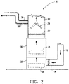
- FIG. 2 shows the application of a flame arrestor in a stationary heating/air conditioning system 10 (sometimes referred to as an integrated heating/cooling unit).
- 12 is the return air duct from a space to be heated or cooled, for instance a house. Return air from the space flows through the duct 12 through a filter 14 into a blowing unit 20.
- the blowing unit contains a blower or fan to move the air into the furnace 30 and from there through the evaporator unit 40 and into the ductwork that routes the air into the house or other space to be heated.
- the furnace includes a heating element 18, which may be a gas (e.g., propane or natural gas) or oil flame or electric heating element or coil.
- the evaporator unit 40 includes the metal mesh flame arrestor 22 and an evaporator 24, which contains refrigerant.
- Refrigerant flows into the evaporator through line 26 from an outside unit comprising a compressor and condenser to complete the vapor compression cooling/heating circuit and then flows back to the outside unit through line 28.
- any flame from the furnace unit would be arrested and prevented from extending past the metal mesh flame arrestor.
- the evaporator unit of the system shown in FIG. 2 may be part of a dedicated air conditioner system (for just cooling) or part of a heat pump system that provides cooling and heating (when outside temperatures allow). In the case of a heat pump, the furnace would serve as a back-up heating system for lower outside temperature conditions.
- the metal mesh flame arrestor may encapsulate a refrigerant source, such that if there is a leak from tubing that circulates flammable refrigerant material, the metal mesh can restrict any damage from ignition of the refrigerant to substantially within the refrigerant source and mitigate damage to areas beyond the refrigerant source.
- An 8 oz tin plated aerosol can was filled with about 175 grams of refrigerant compositions and fitted with an Acc-U-Sol actuator (Precision Valve Company).
- a standard plumber's candle 3.5 inches tall, was lit.
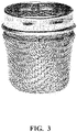
- a cup shaped flame arrestor with a closed top, a height of 45 mm, a base diameter of 40 mm and hole sizes varying from 0.5 mm to 1.2 mm (see FIG. 3 ) was placed over the flame to cover the flame and wick.
- Refrigerant compositions were sprayed liquid phase horizontally from about 10 inches away from the candle at the height of the flame and flame extension behavior was observed. Results are shown in Table 1 below: Table 1 Refrigerant Composition Refrigerant Composition.
- Results show the flame arrestor is capable of containing a flame exposed to HFO-1234yf or HFO-1234yf/HFC-152a mixtures and thereby improving safety of these refrigerant compositions.
- Results show the flame arrestor is effective at containing a flame exposed to HF0-1234yf/lubricant mixtures and thereby improving safety of these refrigerant/lubricant compositions.
- UCON-244 is a polyalkylene glycol compressor lubricant supplied by Dow (Midland, Michigan).
- An 8 oz tin plated aerosol can was filled with about 175 grams of refrigerant compositions and fitted with an Acc-U-Sol actuator.
- Flat woven 304 stainless steel wire screens of varying mesh size, opening size and wire diameter (McMaster-Carr, Elmhurst, Illinois) were placed vertically next to the candle on the side away from the aerosol can.
- the refrigerant compositions were sprayed liquid phase horizontally from about 10 inches away from the candle at the height of the flame. The flame extension was observed as to whether the flame traveled through the screen or was arrested upon spraying.
- An 8 oz tin plated aerosol can was filled with about 175 grams of refrigerant compositions and fitted with an Acc-U-Sol actuator.
- Flat woven aluminum wire screen of varying mesh size, opening size and wire diameter (McMaster-Carr, Elmhurst, Illinois) was placed vertically next to the candle on the side away from the aerosol can.
- the refrigerant compositions were sprayed liquid phase horizontally from about 10 inches away from the candle at the height of the flame. The flame extension was observed as to whether the flame traveled through the screen or was arrested upon spraying.
- An 8 oz tin plated aerosol can was filled with about 175 grams of refrigerant compositions and fitted with an Acc-U-Sol actuator.
- a flat aluminum mosquito screen was placed vertically next to the candle on the side away from the aerosol can.
- the refrigerant compositions were sprayed liquid phase horizontally from about 10 inches away from the candle at the height of the flame. The flame extension was observed as to whether the flame traveled through the screen or was arrested upon spraying. Results are shown in Table 5 below: Table 5 Material Material Type Mesh Size (per inch) Wire Diameter (in) Refrigerant Flame prevented from travel thru screen?
- Results show that a design as simple as a mosquito screen is also effective at arresting flames of trans-HFO-1234ze, HFO-1234yf and HFC-32.
- An 8 oz tin plated aerosol can was filled with about 175 grams of refrigerant compositions of the present invention and fitted with an Acc-U-Sol actuator.
- Two flat 304 SS woven screens were vertically positioned directly next to the candle with the screens overlapping each other and the holes offset. The screens were offset by centering the intersection of one wire screen in the open area between wires of the second wire screen. This arrangement was compared to a single screen which had failed in previous tests.
- the refrigerant compositions were sprayed liquid phase horizontally from about 10 inches away from the candle at the height of the flame. The flame extension was observed as to whether the flame traveled through the screen or was arrested upon spraying.
- results show metal mesh flame arrestors can also be effective when two screens are placed over each other with the holes lined up in an offset position to provide an additional path of resistance for the flame.
- the offset wire screens served to reduce the open area of the flame arrestor. This was effective for trans-HFO-1234ze, HFO-1234yf and HFC-32.
Landscapes
- Health & Medical Sciences (AREA)
- Public Health (AREA)
- Business, Economics & Management (AREA)
- Emergency Management (AREA)
- Chemical & Material Sciences (AREA)
- Engineering & Computer Science (AREA)
- Chemical Kinetics & Catalysis (AREA)
- General Chemical & Material Sciences (AREA)
- Oil, Petroleum & Natural Gas (AREA)
- Fireproofing Substances (AREA)
- Cooling Or The Like Of Semiconductors Or Solid State Devices (AREA)
- Air-Conditioning For Vehicles (AREA)
Abstract
Description
- The disclosed invention is in the field of flame arrestors for use with refrigerant and air conditioning systems, particularly mobile and stationary refrigerant and air conditioning systems.
- The refrigeration industry has been working for the past few decades to find replacement refrigerants for the ozone depleting chlorofluorocarbons (CFCs) and hydrochlorofluorocarbons (HCFCs) being phased out as a result of the Montreal Protocol. The solution for most refrigerant producers has been the commercialization of hydrofluorocarbon (HFC) refrigerants. The new HFC refrigerants, including HFC-134a, have zero ozone depletion potential and thus are not affected by the current regulatory phase out as a result of the Montreal Protocol.
- Further environmental regulations may ultimately cause global phase out of certain HFC refrigerants. Currently, industry is facing regulations relating to global warming potential (GWP) for refrigerants used in mobile air conditioning. Should the regulations be more broadly applied in the future, for instance for stationary air conditioning and refrigeration systems, an even greater need will be felt for refrigerants that can be used in all areas of the refrigeration and air-conditioning industry. In order to achieve low GWP, hydrofluorocarbon and hydrocarbon refrigerants with various levels of flammability have been proposed
- Refrigerant systems, such as air conditioning, refrigeration or heat pump systems, using flammable refrigerants may leak or otherwise escape from the refrigerant container or tubing due to vehicle accident or system malfunction. When the refrigerants are exposed to potential ignition sources, such as those within an automobile engine compartment, the potential for fire is present. For example, in the event that the refrigerant lines or containers are cut, punctured, ruptured, or otherwise damaged, such as in an automobile accident, the flammable refrigerants may contact certain ignition sources and thus lead to a fire. Systems are needed to prevent ignition of refrigerants and to otherwise mitigate the spread of a fire to other nearby combustible materials that may further damage property or materials within the vicinity of the ignition or be a risk to passengers.
- The present invention provides a method for reducing the propagation of a flame to or from a refrigerant source and an ignition source in or adjacent to a cooling system, comprising positioning a metal mesh flame arrestor between said refrigerant source and said ignition source.
- The general description and the following detailed description are exemplary and explanatory only and are not restrictive of the invention, as defined in the appended claims.
- For the purpose of illustrating the invention, there are shown in the drawings exemplary embodiments of the invention; however, the invention is not limited to the specific methods, compositions, and devices disclosed. In addition, the drawings are not necessarily drawn to scale. In the drawings:
-
FIG. 1 illustrates one embodiment of the present invention directed to an automobile exhaust manifold, in which the manifold components are covered with a flame arrestor. -
FIG. 2 illustrates one embodiment of the present invention directed to a stationary heating and cooling system for, for instance, a residential furnace/air conditioner, in which the flame arrestor is positioned between the heat source of the furnace and the evaporator. -
FIG. 3 is a picture of the cup-shaped flame arrestor used in Examples 1 and 2. - It is to be understood that this invention is not limited to the specific devices, methods, applications, conditions or parameters described and/or shown herein, and that the terminology used herein is for the purpose of describing particular embodiments by way of example only and is not intended to be limiting of the claimed invention. Also, as used in the specification including the appended claims, the singular forms "a," "an," and "the" include the plural, and reference to a particular numerical value includes at least that particular value, unless the context clearly dictates otherwise. The term "plurality", as used herein, means more than one. When a range of values is expressed, another embodiment includes from the one particular value and/or to the other particular value. Similarly, when values are expressed as approximations, by use of the antecedent "about," it will be understood that the particular value forms another embodiment. All ranges are inclusive and combinable.
- It is to be appreciated that certain features of the invention which are, for clarity, described herein in the context of separate embodiments, may also be provided in combination in a single embodiment. Conversely, various features of the invention that are, for brevity, described in the context of a single embodiment, may also be provided separately or in any subcombination. Further, reference to values stated in ranges include each and every value within that range.
- Various ignition sources may exist in cooling systems using refrigerant working fluids. As an example, refrigerant is contained in an air conditioning system for an automobile that is contained within the automobile's engine compartment. These sources include, for example, fuses, electrical heaters, engine exhaust manifolds, catalytic converters, or turbo chargers, and the hot surfaces associated with such sources. These ignition sources may be where a fire or spark starts or develops or potentially where a flame may travel.
- Cooling systems include refrigeration systems, air conditioning systems, and heat pump systems, as well as, combined air conditioning and heating systems, such as integrated heating/cooling systems that include a furnace. These systems include air conditioners, freezers, refrigerators, heat pumps, water chillers, flooded evaporator chillers, direct expansion chillers, walk-in coolers, heat pumps, mobile refrigerators, mobile air conditioning units and combinations thereof.
- As used herein, mobile heat transfer system refers to any refrigeration, air conditioner, or heating apparatus incorporated into a transportation unit for the road, rail, sea or air. In addition, mobile refrigeration or air conditioner units, include those apparatus that are independent of any moving carrier and are known as "intermodal" systems. Such intermodal systems include "container' (combined sea/land transport) as well as "swap bodies" (combined road/rail transport).
- As used herein, stationary heat transfer systems are systems that are fixed in place during operation. A stationary heat transfer system may be associated within or attached to buildings of any variety or may be standalone devices located out of doors, such as a drink or snack vending machine. These stationary applications may be stationary air conditioning and heat pumps (including but not limited to chillers, high temperature heat pumps, residential air conditioners, commercial or industrial air conditioning systems, and including window, ductless, ducted, packaged terminal, chillers, and those exterior but connected to the building such as rooftop systems). In stationary refrigeration applications, the disclosed compositions may be useful in equipment including commercial, industrial or residential refrigerators and freezers, ice machines, self-contained coolers and freezers, flooded evaporator chillers, direct expansion chillers, walk-in and reach-in coolers and freezers, and combination systems. In some embodiments, the disclosed compositions may be used in supermarket refrigeration systems. Additionally, stationary systems include secondary loop systems that utilize a primary refrigerant and a secondary heat transfer fluid.
- A flammable refrigerant is a refrigerant with the ability to ignite and/or propagate a flame in the presence of air. The flammability of a refrigerant is determined under test conditions specified in ASTM (American Society of Testing and Materials) E681. The test data indicates if the composition is flammable at specified temperatures (as designated by ASHRAE (American Society of Heating, Refrigerating and Air-Conditioning Engineers) in ASHRAE Standard 34).
- Examples of refrigerant sources include automotive air conditioning or heat pump systems and stationary furnaces or air conditioning/furnace combination systems. Such systems may comprise refrigerants that comprise one or more tetrafluoropropenes. The present invention is particularly useful in arresting the propagation of flames exposed to low GWP tetrafluoropropene refrigerants, such as 2,3,3,3-tetrafluoropropene (HF0-1234yf); cis-1,3,3,3-tetrafluoropropene (cis-HFO-1234ze); trans-1,3,3,3-tetrafluoropropene (trans-HF0-1234ze); cis-1,2,3,3-tetrafluoropropene (cis-HF0-1234ye); trans-1,2,3,3-tetrafluoropropene (trans-HFO-1234ye); 1,1,2,3-tetrafluoropropene (HF0-1234yc); and 1,1,3,3-tetrafluoropropene (HFO-1234zc). Other types of flammable refrigerants that may be found in engine compartments include 1,1-difluoroethane (HFC-152a) and difluoromethane (HFC-32). Additionally, flammable refrigerants that may be found in engine compartments include mixtures of tetrafluoropropenes with difluoromethane (HFC-32) and/or 1,1-difluoroethane (HFC-152a). In one embodiment, the refrigerant comprises 2,3,3,3-tetrafluoropropene. In another embodiment, the refrigerant comprises trans-1,3,3,3-tetrafluoropropene. In another embodiment, the refrigerant comprises difluoromethane. In another embodiment, the refrigerant comprises 1,1-difluoroethane.
- Containment systems are needed to prevent the ignition of flammable refrigerants or to contain or mitigate the spread of fire from the ignition of the refrigerant. For example, refrigerant may leak from tubing or a vessel holding the refrigerant and the refrigerant may ignite when exposed to a flame, hot surface, or spark. The present disclosure relates to the use of particular flame arrestors, such as those useful in arresting the propagation of flames exposed to tetrafluoropropene or other flammable refrigerants as described above.
- A flame arrestor functions by forcing a flame front through channels too narrow to permit the continuance of a flame. These passages can be regular, like metal mesh (e.g., wire mesh) or a sheet metal plate with punched holes, or irregular, such as those in random packing. The required size of the channels needed to stop a flame front can vary significantly, depending on the flammability properties of the leaking refrigerant.
- Metal mesh flame arrestors are particularly useful in connection with the present invention. These arrestors typically comprise planar sheets but may also take other shapes depending on the application of interest. For example, the metal mesh flame arrestor may be flexible so as to wrap around a particular ignition or refrigerant source.
- The flame arrestors of the present invention may be comprised of metals such as 316 stainless steel, 304 stainless steel, carbon steel, aluminum, or copper. In one embodiment, the mesh has an open area of about 60% or less, more preferably 52% or less. In certain embodiments, the metal mesh flame arrestors with symmetrical hole sizes have an opening width of .028 inches or less, more preferably 0.023 inches or less.
- The mesh size is indicated by "mesh per inch". The mesh per inch dimension is the number of openings (or channels, as described above) within an inch of the wire sheet. This dimension is expressed as two numbers, such as 3x3, which means there are three openings horizontally and three openings vertically in one inch. Open area (or open space) is the percent of the screen area that is made up of openings (or channels) in the mesh.
- In another embodiment of the invention, two or more metal mesh sheets may be used. For example, the two or more metal mesh sheets may be positioned so that the mesh holes of each sheet are lined up in an offset position, and may define various opening widths and open areas effective for reducing the propagation of a flame. In certain embodiments, the two or more metal mesh screens may be lined up to create an overall metal mesh flame arrestor with a preferred open area of about 63% or less, and an opening width of the mesh of about 0.132 inches or less, more preferred is an open area of about 56% or less and width of mesh of about 0.075 inches or less.
- The flame arrestor is typically positioned between the refrigerant source and the ignition source, preferably close to the ignition source to prevent significant propagation of the flame away from the ignition source. For example, the possibility of engine damage may be reduced by preventing a flame from propagating from an automobile exhaust manifold. This may be accomplished by wrapping a metal mesh flame arrestor around an exhaust manifold, thereby prohibiting the passage of flame away from the exhaust manifold in the event the hot manifold is exposed to leaking refrigerant and an ignition occurs.
- In some embodiments, the distance of the metal mesh from the ignition source will vary from a few millimeters to a few centimeters. In one embodiment, the distance between the metal mesh and the ignition source is from about 2 mm to about 5 cm. In another embodiment, the distance between the metal mesh and the ignition source is from about 5 mm to about 3 cm. In another embodiment, the distance between the metal mesh and the ignition source is from about 1 cm to about 2 cm.
FIG. 1 illustrates an embodiment where the metal mesh flame arrestor is wrapped around a manifold. Therefore, if there is a leak from the air conditioning system and the refrigerant vapor or liquid travels through the flame arrestor mesh and ignites with a hot surface, such as an exhaust manifold (or other ignition source), the flame front may attempt to spread, but can be stopped from passing back through the metal mesh flame arrestor if the hole size, for example, is correctly designed for the type of flame encountered. - With reference to
FIG. 1 , a flame arrestor is shown in one embodiment of a mobile system including an air conditioner containing refrigerant. In particular, an exhaust manifold of an automobile is shown inFIG. 1 with a flame arrestor attached. Theengine block 110 has multiple outlets for exhaust air. These outlets are connected to theexhaust manifold 112. The exhaust air flows out of the engine block through the outlets and into the exhaust manifold. The multiple exhaust air streams are merged into a single steam that flows into theexhaust pipe 116. The metalmesh flame arrestor 120 covers theentire exhaust manifold 112 from theconnections 118 for the engine block to theconnection 114 for the exhaust pipe. In another embodiment, the metal mesh flame arrestor may optionally be extended to cover at least some portion of theexhaust pipe 116, shown inFIG. 1 as 120a. The metal mesh flame arrestor may be attached by any means sufficient to hold it in place. Means for connecting the metal mesh flame arrestor to an exhaust manifold, for example, include welding (e.g., continuous welds or spot welds), brazing, and fasteners such as screws or bolts. In one embodiment, existing fasteners, for instance the bolts used to attach the exhaust manifold to the engine block at 118 inFIG. 1 may be utilized. In another embodiment, the flame arrestor may be incorporated in the design of new systems.FIG. 1 shows a single metal mesh flame arrestor covering the entire exhaust manifold, however in other embodiments, individual metal mesh flame arrestors may surround each pipe of the exhaust manifold. -
FIG. 2 shows the application of a flame arrestor in a stationary heating/air conditioning system 10 (sometimes referred to as an integrated heating/cooling unit). InFIG. 2 , 12 is the return air duct from a space to be heated or cooled, for instance a house. Return air from the space flows through theduct 12 through afilter 14 into ablowing unit 20. The blowing unit contains a blower or fan to move the air into thefurnace 30 and from there through the evaporator unit 40 and into the ductwork that routes the air into the house or other space to be heated. The furnace includes aheating element 18, which may be a gas (e.g., propane or natural gas) or oil flame or electric heating element or coil. The evaporator unit 40 includes the metalmesh flame arrestor 22 and anevaporator 24, which contains refrigerant. Refrigerant flows into the evaporator throughline 26 from an outside unit comprising a compressor and condenser to complete the vapor compression cooling/heating circuit and then flows back to the outside unit throughline 28. In the event of a refrigerant leak, any flame from the furnace unit would be arrested and prevented from extending past the metal mesh flame arrestor. - The evaporator unit of the system shown in
FIG. 2 may be part of a dedicated air conditioner system (for just cooling) or part of a heat pump system that provides cooling and heating (when outside temperatures allow). In the case of a heat pump, the furnace would serve as a back-up heating system for lower outside temperature conditions. - In an alternative embodiment, the metal mesh flame arrestor may encapsulate a refrigerant source, such that if there is a leak from tubing that circulates flammable refrigerant material, the metal mesh can restrict any damage from ignition of the refrigerant to substantially within the refrigerant source and mitigate damage to areas beyond the refrigerant source.
- When ranges are used herein for physical properties, such as mesh size, all combinations, and subcombinations of ranges for specific embodiments therein are intended to be included.
- Those skilled in the art will appreciate that numerous changes and modifications can be made to the preferred embodiments of the invention and that such changes and modifications can be made without departing from the spirit of the invention. It is, therefore, intended that the appended claims cover all such equivalent variations as fall within the true spirit and scope of the invention.
- An 8 oz tin plated aerosol can was filled with about 175 grams of refrigerant compositions and fitted with an Acc-U-Sol actuator (Precision Valve Company). A standard plumber's candle, 3.5 inches tall, was lit. A cup shaped flame arrestor with a closed top, a height of 45 mm, a base diameter of 40 mm and hole sizes varying from 0.5 mm to 1.2 mm (see
FIG. 3 ) was placed over the flame to cover the flame and wick. Refrigerant compositions were sprayed liquid phase horizontally from about 10 inches away from the candle at the height of the flame and flame extension behavior was observed. Results are shown in Table 1 below:Table 1 Refrigerant Composition Refrigerant Composition. (wt%) Flame Arrestor Present? Observation HF0-1234yf 100 No -1 inch flame extension then self-extinguished HFC-152a 100 No -14 inch flame extension HF0-1234yf/HFC-152a 50/50 No - 8 inch flame extension HF0-1234yf 100 Yes Flame stayed contained inside arrestor HFC-152a 100 Yes Flame extended beyond arrestor -2 inches, then flash back to aerosol can HFO-1234yf/HFC-152a 50/50 Yes Flame stayed contained inside arrestor - Results show the flame arrestor is capable of containing a flame exposed to HFO-1234yf or HFO-1234yf/HFC-152a mixtures and thereby improving safety of these refrigerant compositions.
- An 8 ounce tin plated aerosol can was filled with about 175 grams of refrigerant and lubricant compositions and fitted with an Acc-U-Sol actuator. A standard plumbers candle, 3.5 inches tall, was lit and the flame arrestor of Example 1 was placed over the flame to cover the flame and wick. The compositions were sprayed liquid phase horizontally from about 10 inches away from the candle at the height of the flame and flame extension behavior was observed. Results are shown in Table 2 below:
Table 2 Refrigerant Composition Refrigerant Composition (wt%) Lubricant Composition UCON 244 PAG (wt%) Flame Arrestor Present? Observation HFO-1234yf 99 1 No -1 inch flame extension then extinguished HFO-1234yf 97 3 No -1.5 inch flame extension then extinguished HFO-1234yf 93 7 No -4.5 inch flame extension then extinguished HFO-1234yf 99 1 Yes Flame stayed contained inside arrestor, then self-extinguished HF0-1234yf 97 3 Yes Flame stayed contained inside arrestor HF0-1234yf 93 7 Yes Flame stayed contained inside arrestor - Results show the flame arrestor is effective at containing a flame exposed to HF0-1234yf/lubricant mixtures and thereby improving safety of these refrigerant/lubricant compositions. UCON-244 is a polyalkylene glycol compressor lubricant supplied by Dow (Midland, Michigan).
- An 8 oz tin plated aerosol can was filled with about 175 grams of refrigerant compositions and fitted with an Acc-U-Sol actuator. A standard plumber's candle, 3.5 inches tall, was lit. Flat woven 304 stainless steel wire screens of varying mesh size, opening size and wire diameter (McMaster-Carr, Elmhurst, Illinois) were placed vertically next to the candle on the side away from the aerosol can. The refrigerant compositions were sprayed liquid phase horizontally from about 10 inches away from the candle at the height of the flame. The flame extension was observed as to whether the flame traveled through the screen or was arrested upon spraying. Results are shown in Table 3 below:
Table 3 Material Material Type Mesh Size (per inch) Wire Diameter (in) Opening Width (in) Open Area (%) Refrigerant Was flame arrested? (Y or N) 304SS Wire screen Thick Wire 2X2 0.063 0.437 76.4 t-1234ze No 1234vf No 32 No 152a No 304SS Wire screen Thin Wire 3X3 0.047 0.286 73.6 t-1234ze No 1234yf No 32 No 152a No 304SS Wire screen Thick Wire 3X3 0.063 0.270 65.6 t-1234ze No 1234yf No 32 No 152a No 304SS Wire screen Thin Wire 6X6 0.035 0.132 62.7 t-1234ze No 1234yf No 32 No 152a No 304SS Wire screen Thick Wire 6X6 0.063 0.104 38.9 t-1234ze Yes 1234vf Yes 32 Yes 152a No 304SS Wire screen Thin Wire 8X8 0.028 0.097 60.2 t-1234ze Yes 1234yf Yes 32 Yes 152a No 304SS Wire screen Thin Wire 10X10 0.025 0.075 56.3 t-1234ze Yes 1234yf Yes 32 Yes 152a No 304SS Wire screen Thin Wire 12X12 0.023 0.060 51.8 t-1234ze Yes 1234vf Yes 32 Yes 152a No 304SS Wire screen Thin Wire 20X20 0.016 0.034 46.2 t-1234ze Yes 1234yf Yes 32 Yes 152a No - The results show that stainless steel wire mesh with open area of about 60% or less will arrest flames from trans-HF0-1 234ze, HF0-1234yf and HFC-32which have relatively lowflame propagation characteristics (burning velocity less than 10 cm/sec). This open area corresponds to a screen mesh size of 8X8 or greater.
- An 8 oz tin plated aerosol can was filled with about 175 grams of refrigerant compositions and fitted with an Acc-U-Sol actuator. A standard plumbers candle, 3.5 inches tall, was lit. Flat woven aluminum wire screen of varying mesh size, opening size and wire diameter (McMaster-Carr, Elmhurst, Illinois) was placed vertically next to the candle on the side away from the aerosol can. The refrigerant compositions were sprayed liquid phase horizontally from about 10 inches away from the candle at the height of the flame. The flame extension was observed as to whether the flame traveled through the screen or was arrested upon spraying. Results are shown in Table 4 below:
Table 4 Material Material Type Mesh Size (per inch) Wire Diameter (in) Opening Width (in) Open Area (%) Refrigerant Was flame arrested? (Y or N) Aluminum Wire screen Thick Wire 2X2 0.063 0.437 76.4 t-1234ze No 1234vf No 32 No 152a No Aluminum Wire screen Thin Wire 6X6 0.035 0.132 62.7 t-1234ze No 1234vf No 32 No 152a No Aluminum Wire screen Thin Wire 8X8 0.028 0.097 60.2 t-1234ze Yes 1234vf No 32 Yes 152a No Aluminum Wire screen Thin Wire 10X10 0.025 0.075 56.3 t-1234ze Yes 1234yf Yes 32 Yes 152a No Aluminum Wire screen Thin Wire 12X12 0.023 0.06 51.8 t-1234ze Yes 1234vf Yes 32 Yes 152a No Aluminum Wire screen Thin Wire 20X20 0.016 0.034 46.2 t-1234ze Yes 1234yf Yes 32 Yes 152a No - The results show that aluminum wire mesh with open area of about 60% or less (8X8 mesh or greater) will arrest flames from trans-HFO-1234ze, and HFC-32 while mess with open area about 56% or less (10X10 mesh or greater) will arrest HFO-1234yf.
- An 8 oz tin plated aerosol can was filled with about 175 grams of refrigerant compositions and fitted with an Acc-U-Sol actuator. A standard plumbers candle, 3.5 inches tall, was lit. A flat aluminum mosquito screen was placed vertically next to the candle on the side away from the aerosol can. The refrigerant compositions were sprayed liquid phase horizontally from about 10 inches away from the candle at the height of the flame. The flame extension was observed as to whether the flame traveled through the screen or was arrested upon spraying. Results are shown in Table 5 below:
Table 5 Material Material Type Mesh Size (per inch) Wire Diameter (in) Refrigerant Flame prevented from travel thru screen? (Y or N) Aluminum Mosquito screen 16X16 0.008 trans-1234ze Yes Aluminum Mosquito screen 16X16 0.008 1234yf Yes Aluminum Mosquito screen 16X16 0.008 32 Yes Aluminum Mosquito screen 16X16 0.008 152a No - Results show that a design as simple as a mosquito screen is also effective at arresting flames of trans-HFO-1234ze, HFO-1234yf and HFC-32.
- An 8 oz tin plated aerosol can was filled with about 175 grams of refrigerant compositions of the present invention and fitted with an Acc-U-Sol actuator. A standard plumbers candle, 3.5 inches tall, was lit. Two flat 304 SS woven screens were vertically positioned directly next to the candle with the screens overlapping each other and the holes offset. The screens were offset by centering the intersection of one wire screen in the open area between wires of the second wire screen. This
arrangement was compared to a single screen which had failed in previous tests. The refrigerant compositions were sprayed liquid phase horizontally from about 10 inches away from the candle at the height of the flame. The flame extension was observed as to whether the flame
traveled through the screen or was arrested upon spraying. Results are shown in Table 6 below:Table 6 Material Material Type Mesh Size (per inch) Wire Diameter (in) Opening Width (in) Open Area (%) Refrigerant Was flame arrested? (Y or N) 304SS Wire screen, Single screen, Thin Wire 6X6 0.035 0.132 62.7 trans-1234ze No 1234vf No 32 No 152a No 304SS Wire screen, Two screens overlapping, Thin Wire 6X6 0.035 0.132 62.7 trans-1234ze Yes 1234yf Yes 32 Yes 152a No - Results show metal mesh flame arrestors can also be effective when two screens are placed over each other with the holes lined up in an offset position to provide an additional path of resistance for the flame. The offset wire screens served to reduce the open area of the flame arrestor.
This was effective for trans-HFO-1234ze, HFO-1234yf and HFC-32. - The application also concerns the following embodiments:
- Embodiment 1. A method for reducing the propagation of a flame to or from a refrigerant source and an ignition source in or adjacent to a cooling system, comprising positioning a metal mesh flame arrestor between said refrigerant source and said ignition source.
- Embodiment 2. The method of embodiment 1, wherein said refrigerant source is an air conditioning or heat pump system.
- Embodiment 3. The method of embodiment 1, wherein said refrigerant source comprises one or more tetrafluoropropenes and the arrestor reduces the propagation of a flame exposed to said tetrafluoropropenes.
- Embodiment 4. The method of embodiment 3, wherein said refrigerant comprises a mixture of one or more tetrafluoropropenes with difluoromethane or 1,1-difluoroethane.
- Embodiment 5. The method of embodiment 3, wherein said tetrafluoropropenes comprise 2,3,3,3-tetrafluoropropene; cis-1,3,3,3-tetrafluoropropene; trans-1,3,3,3-tetrafluoropropene; cis-1,2,3,3-tetrafluoropropene; trans-1,2,3,3-tetrafluoropropene; 1,1,2,3-tetrafluoropropene; or 1,1,3,3-tetrafluoropropene; or mixtures thereof.
- Embodiment 6. The method of embodiment 1, wherein said refrigerant source comprises difluoromethane and the arrestor reduces the propagation of a flame exposed to said difluoromethane.
- Embodiment 7. The method of embodiment 1, wherein said refrigerant source comprises 1,1-difluoroethane and the arrestor reduces the propagation of a flame exposed to said 1,1-difluoroethane.
- Embodiment 8. The method of embodiment 1, wherein said metal mesh is 316 stainless steel, 304 stainless steel, carbon steel or aluminium.
- Embodiment 9. The method of embodiment 8, wherein said metal mesh has an open area of about 60% or less.
-
Embodiment 10. The method of embodiment 8, wherein said metal mesh has an opening width of from about 0.2 mm to about 2.6 mm. - Embodiment 11. The method of embodiment 1, wherein said metal mesh is wrapped around the ignition source.
-
Embodiment 12. The method of embodiment 1, wherein two or more metal mesh flame arrestors are positioned and wherein the metal mesh holes of each arrestor are lined up in an offset position. - Embodiment 13. The method of embodiment 1, wherein said ignition source is an engine exhaust manifold, a fuse, an electric heater, a catalytic converter or a turbo charger.
-
Embodiment 14. The method of embodiment 1 , wherein said ignition source is a heating element or flame from a furnace.
Claims (11)
- A method for reducing the propagation of a flame to or from a refrigerant source and an ignition source in or adjacent to a cooling system, comprising positioning a metal mesh flame arrestor between said refrigerant source and said ignition source, wherein said refrigerant source comprises one or more tetrafluoropropenes and the arrestor reduces the propagation of a flame exposed to said tetrafluoropropenes, and wherein said metal mesh has an open area of about 60% or less, and an opening width of from about 0.2 mm to about 2.6 mm.
- The method of claim 1, wherein said refrigerant source is an air conditioning or heat pump system.
- The method of claim 1, wherein said refrigerant comprises a mixture of one or more tetrafluoropropenes with difluoromethane or 1,1-difluoroethane.
- The method of claim 3, wherein said tetrafluoropropenes comprise 2,3,3,3-tetrafluoropropene; cis-1,3,3,3-tetrafluoropropene; trans-1,3,3,3-tetrafluoropropene; cis-1,2,3,3-tetrafluoropropene; trans-1,2,3,3-tetrafluoropropene; 1,1,2,3-tetrafluoropropene; or 1,1,3,3-tetrafluoropropene; or mixtures thereof.
- The method of claim 1, wherein said refrigerant source comprises difluoromethane and the arrestor reduces the propagation of a flame exposed to said difluoromethane.
- The method of claim 1, wherein said refrigerant source comprises 1,1-difluoroethane and the arrestor reduces the propagation of a flame exposed to said 1,1-difluoroethane.
- The method of claim 1, wherein said metal mesh is wrapped around the ignition source.
- The method of claim 1, wherein said metal mesh is 316 stainless steel, 304 stainless steel, carbon steel or aluminium.
- The method of claim 1, wherein two or more metal mesh flame arrestors are positioned and wherein the metal mesh holes of each arrestor are lined up in an offset position.
- The method of claim 1, wherein said ignition source is an engine exhaust manifold, a fuse, an electric heater, a catalytic converter or a turbo charger.
- The method of claim 1 , wherein said ignition source is a heating element or flame from a furnace.
Applications Claiming Priority (3)
| Application Number | Priority Date | Filing Date | Title |
|---|---|---|---|
| US201161431587P | 2011-01-11 | 2011-01-11 | |
| EP12702917.1A EP2663373A2 (en) | 2011-01-11 | 2012-01-11 | Methods of reducing flame propogation in systems with a flammable refrigerant |
| PCT/US2012/020936 WO2012097060A2 (en) | 2011-01-11 | 2012-01-11 | Methods of reducing flame propogation in systems with a flammable refrigerant |
Related Parent Applications (1)
| Application Number | Title | Priority Date | Filing Date |
|---|---|---|---|
| EP12702917.1A Division EP2663373A2 (en) | 2011-01-11 | 2012-01-11 | Methods of reducing flame propogation in systems with a flammable refrigerant |
Publications (1)
| Publication Number | Publication Date |
|---|---|
| EP4101508A1 true EP4101508A1 (en) | 2022-12-14 |
Family
ID=45567117
Family Applications (2)
| Application Number | Title | Priority Date | Filing Date |
|---|---|---|---|
| EP12702917.1A Ceased EP2663373A2 (en) | 2011-01-11 | 2012-01-11 | Methods of reducing flame propogation in systems with a flammable refrigerant |
| EP22181782.8A Pending EP4101508A1 (en) | 2011-01-11 | 2012-01-11 | Methods of reducing flame propogation in systems with a flammable refrigerant |
Family Applications Before (1)
| Application Number | Title | Priority Date | Filing Date |
|---|---|---|---|
| EP12702917.1A Ceased EP2663373A2 (en) | 2011-01-11 | 2012-01-11 | Methods of reducing flame propogation in systems with a flammable refrigerant |
Country Status (9)
| Country | Link |
|---|---|
| US (1) | US9295860B2 (en) |
| EP (2) | EP2663373A2 (en) |
| JP (1) | JP6280745B2 (en) |
| KR (3) | KR101920096B1 (en) |
| CN (2) | CN108498980B (en) |
| AU (1) | AU2012205640B2 (en) |
| CA (1) | CA2824177A1 (en) |
| MX (1) | MX2013007990A (en) |
| WO (1) | WO2012097060A2 (en) |
Families Citing this family (13)
| Publication number | Priority date | Publication date | Assignee | Title |
|---|---|---|---|---|
| FR3003177B1 (en) | 2013-03-18 | 2017-09-01 | Arkema France | VEHICLE SAFETY DEVICE COMPRISING AN AIR CONDITIONING SYSTEM COMPRISING A FLAMMABLE REFRIGERANT FLUID AND METHOD FOR PREVENTING RISK OF INFLAMMING THE REFRIGERANT FLUID |
| EP3022497B1 (en) * | 2013-07-15 | 2023-09-20 | Carrier Corporation | Flame arrestors for use with a hvac/r system |
| US9731155B2 (en) * | 2014-09-05 | 2017-08-15 | Empyreus Solutions Llc | Flame arrester with porous sleeve |
| EP3001545B1 (en) | 2014-09-26 | 2018-06-06 | Weg Equipamentos Electricos S.A. | Internal pressure attenuator device for rotating electrical machines able to operate in explosive atmospheres |
| CN106999744A (en) * | 2014-10-16 | 2017-08-01 | 开利公司 | Fire extinguishing system and method |
| DE102015219562A1 (en) * | 2015-10-09 | 2017-04-13 | Bayerische Motoren Werke Aktiengesellschaft | motor vehicle |
| US20230218937A1 (en) * | 2017-06-27 | 2023-07-13 | Mark David GROBEN | Wildfire containment methods |
| CN107998540B (en) * | 2017-12-05 | 2020-04-14 | 大连理工大学 | A reusable explosion suppression and pressure relief device |
| DE102018127198A1 (en) | 2018-10-31 | 2020-04-30 | Vaillant Gmbh | Molded parts for heat pumps |
| JP2020106250A (en) * | 2018-12-28 | 2020-07-09 | ダイキン工業株式会社 | Combustion heater and air conditioning system |
| CN119486785A (en) | 2022-05-04 | 2025-02-18 | 里克有限责任公司 | Flame-mitigating closure systems and containers |
| US20250249300A1 (en) * | 2024-02-02 | 2025-08-07 | Daikin Comfort Technologies Manufacturing, L.P. | Gas furnace with flame arrestor |
| US20260097885A1 (en) | 2024-10-04 | 2026-04-09 | Rieke Llc | Container and closure systems with flame mitigation |
Citations (4)
| Publication number | Priority date | Publication date | Assignee | Title |
|---|---|---|---|---|
| DE523513C (en) * | 1929-04-23 | 1931-05-02 | Joseph Hausen Dr | Device to prevent room explosions |
| EP0117864A1 (en) * | 1983-01-25 | 1984-09-05 | Jenbacher Werke AG | Combustion engine |
| US5415233A (en) * | 1992-06-30 | 1995-05-16 | Chem-Mech | Flame arrestor apparatus |
| EP0947782A1 (en) * | 1997-10-21 | 1999-10-06 | Matsushita Electric Industrial Co., Ltd. | Explosion preventing apparatus for refrigerating machines using inflammable refrigerant |
Family Cites Families (23)
| Publication number | Priority date | Publication date | Assignee | Title |
|---|---|---|---|---|
| US3961900A (en) * | 1973-06-05 | 1976-06-08 | Catalytic Pollution Controls, Inc. | Combustible vapor detector |
| DE3819832A1 (en) | 1988-06-10 | 1989-12-14 | Michael Dr Spaeth | FIRE PROTECTION FILTER |
| US5203296A (en) * | 1992-04-09 | 1993-04-20 | Barbron Corporation | Flame arrester having helical flame arresting member |
| JPH0755298A (en) * | 1993-08-20 | 1995-03-03 | Matsushita Electric Ind Co Ltd | Air conditioner |
| US20020014218A1 (en) * | 1999-02-16 | 2002-02-07 | Beal Kevin R. | Multiple cylinder rotary motor and method of operation |
| JP2000301939A (en) * | 1999-04-20 | 2000-10-31 | Munenori Narita | Bactericidal and deodorizing system for automobile |
| US6644961B2 (en) * | 2001-03-27 | 2003-11-11 | The Protectoseal Company | Flame arrestor with reflection suppressor |
| JP2003106743A (en) * | 2001-09-27 | 2003-04-09 | Kunihiro Miyake | Glass tube heater for defrosting refrigerator |
| JP3904191B2 (en) * | 2001-10-23 | 2007-04-11 | 本田技研工業株式会社 | Exhaust fuel diluter and exhaust fuel dilution type fuel cell system |
| JP3088849U (en) * | 2002-03-26 | 2002-10-04 | 三菱化学株式会社 | Flameproof wire mesh attached to exhaust port |
| EP2455440A3 (en) * | 2003-11-13 | 2014-02-19 | E. I. du Pont de Nemours and Company | Compositions and methods for reducing fire hazard of flammable refrigerants |
| JP2005251431A (en) * | 2004-03-01 | 2005-09-15 | Denso Corp | Catalytic combustion equipment |
| US7150258B1 (en) | 2005-07-21 | 2006-12-19 | Foundation Coal Development Corporation | System and method for encapsulating high temperature surface portions of a machine component |
| CN1850311A (en) * | 2006-03-31 | 2006-10-25 | 周斌 | Novel fire-retardant core |
| US7874178B2 (en) | 2007-02-09 | 2011-01-25 | Dometic, LLC | Absorption refrigerator flame arrestor system |
| US7730735B2 (en) * | 2007-05-22 | 2010-06-08 | Maruya Richard H | Refrigerant service port valve for air conditioners |
| TW200920721A (en) * | 2007-07-13 | 2009-05-16 | Solvay Fluor Gmbh | Preparation of halogen and hydrogen containing alkenes over metal fluoride catalysts |
| US9550854B2 (en) * | 2007-10-12 | 2017-01-24 | Honeywell International Inc. | Amine catalysts for polyurethane foams |
| JP5435859B2 (en) * | 2007-11-26 | 2014-03-05 | Jx日鉱日石エネルギー株式会社 | Refrigerator oil and working fluid composition for refrigerator |
| JP2009257652A (en) * | 2008-02-29 | 2009-11-05 | Daikin Ind Ltd | Refrigerating apparatus |
| US9994751B2 (en) * | 2008-04-30 | 2018-06-12 | Honeywell International Inc. | Absorption refrigeration cycles using a LGWP refrigerant |
| WO2010008640A1 (en) * | 2008-07-16 | 2010-01-21 | Dow Global Technologies Inc. | Refrigerant compositions including silyl terminated polyalkylene glycols as lubricants and methods for making the same |
| JP4864059B2 (en) * | 2008-09-29 | 2012-01-25 | 三菱電機株式会社 | Heat pump water heater |
-
2012
- 2012-01-11 CA CA2824177A patent/CA2824177A1/en not_active Abandoned
- 2012-01-11 CN CN201810628304.0A patent/CN108498980B/en active Active
- 2012-01-11 KR KR1020137021072A patent/KR101920096B1/en active Active
- 2012-01-11 CN CN201280004945.XA patent/CN103328049B/en active Active
- 2012-01-11 MX MX2013007990A patent/MX2013007990A/en unknown
- 2012-01-11 WO PCT/US2012/020936 patent/WO2012097060A2/en not_active Ceased
- 2012-01-11 KR KR1020197037430A patent/KR102155170B1/en active Active
- 2012-01-11 US US13/978,730 patent/US9295860B2/en active Active
- 2012-01-11 JP JP2013549514A patent/JP6280745B2/en active Active
- 2012-01-11 AU AU2012205640A patent/AU2012205640B2/en not_active Ceased
- 2012-01-11 KR KR1020187027250A patent/KR102059016B1/en active Active
- 2012-01-11 EP EP12702917.1A patent/EP2663373A2/en not_active Ceased
- 2012-01-11 EP EP22181782.8A patent/EP4101508A1/en active Pending
Patent Citations (4)
| Publication number | Priority date | Publication date | Assignee | Title |
|---|---|---|---|---|
| DE523513C (en) * | 1929-04-23 | 1931-05-02 | Joseph Hausen Dr | Device to prevent room explosions |
| EP0117864A1 (en) * | 1983-01-25 | 1984-09-05 | Jenbacher Werke AG | Combustion engine |
| US5415233A (en) * | 1992-06-30 | 1995-05-16 | Chem-Mech | Flame arrestor apparatus |
| EP0947782A1 (en) * | 1997-10-21 | 1999-10-06 | Matsushita Electric Industrial Co., Ltd. | Explosion preventing apparatus for refrigerating machines using inflammable refrigerant |
Non-Patent Citations (1)
| Title |
|---|
| ANONYMOUS: "Davy lamp - Wikipedia", 26 January 2022 (2022-01-26), XP055973091, Retrieved from the Internet <URL:https://en.wikipedia.org/wiki/Davy_lamp> [retrieved on 20221019] * |
Also Published As
| Publication number | Publication date |
|---|---|
| US9295860B2 (en) | 2016-03-29 |
| CA2824177A1 (en) | 2012-07-19 |
| CN103328049B (en) | 2018-05-25 |
| WO2012097060A3 (en) | 2013-01-10 |
| CN103328049A (en) | 2013-09-25 |
| KR102059016B1 (en) | 2019-12-24 |
| KR102155170B1 (en) | 2020-09-11 |
| CN108498980B (en) | 2022-03-08 |
| EP2663373A2 (en) | 2013-11-20 |
| JP2014508570A (en) | 2014-04-10 |
| AU2012205640A1 (en) | 2013-07-11 |
| CN108498980A (en) | 2018-09-07 |
| KR20190142444A (en) | 2019-12-26 |
| JP6280745B2 (en) | 2018-02-14 |
| KR20180108861A (en) | 2018-10-04 |
| MX2013007990A (en) | 2013-08-21 |
| US20130284464A1 (en) | 2013-10-31 |
| KR20140053835A (en) | 2014-05-08 |
| WO2012097060A2 (en) | 2012-07-19 |
| AU2012205640B2 (en) | 2016-02-25 |
| KR101920096B1 (en) | 2018-11-19 |
Similar Documents
| Publication | Publication Date | Title |
|---|---|---|
| US9295860B2 (en) | Methods of reducing flame propogation in systems with a flammable refrigerant | |
| Lee et al. | Performance of virtually non-flammable azeotropic HFO1234yf/HFC134a mixture for HFC134a applications | |
| US11352533B2 (en) | Heat-transfer fluids having reduced flammability | |
| EP3730869A1 (en) | Air conditioning unit | |
| JP7284754B2 (en) | Heat transfer composition, method and system | |
| EP3121242B1 (en) | Working fluid for heat cycle, composition for heat-cycle systems, and heat-cycle system | |
| US6536225B1 (en) | Air conditioner | |
| EP3022497B1 (en) | Flame arrestors for use with a hvac/r system | |
| JP2020502299A (en) | Refrigerants, heat transfer compositions, methods, and systems | |
| EP3974032B1 (en) | Hvac system, method for operating an hvac system and rail vehicle | |
| Colbourne et al. | Development of R290 transport refrigeration system | |
| KR102214064B1 (en) | Refrigeration unit | |
| CN114686175A (en) | Azeotropic compositions of HFO-1234YF and hydrocarbons | |
| JP6583288B2 (en) | Working medium recovery device | |
| KR20250006164A (en) | Composition comprising tetrafluoropropene and hexafluorobutene | |
| Maclaine-cross | Insurance Risk for Hydrocarbon Refrigerants in Car Air-Conditioners | |
| JP2025064644A (en) | Refrigeration equipment | |
| TH80307A (en) | Stabilized iodocarbon mixtures | |
| HK1153220A1 (en) | Compositions comprising 2,3,3,3-tetrafluoropropene | |
| HK1153220B (en) | Compositions comprising 2,3,3,3-tetrafluoropropene |
Legal Events
| Date | Code | Title | Description |
|---|---|---|---|
| PUAI | Public reference made under article 153(3) epc to a published international application that has entered the european phase |
Free format text: ORIGINAL CODE: 0009012 |
|
| STAA | Information on the status of an ep patent application or granted ep patent |
Free format text: STATUS: THE APPLICATION HAS BEEN PUBLISHED |
|
| AC | Divisional application: reference to earlier application |
Ref document number: 2663373 Country of ref document: EP Kind code of ref document: P |
|
| AK | Designated contracting states |
Kind code of ref document: A1 Designated state(s): AL AT BE BG CH CY CZ DE DK EE ES FI FR GB GR HR HU IE IS IT LI LT LU LV MC MK MT NL NO PL PT RO RS SE SI SK SM TR |
|
| STAA | Information on the status of an ep patent application or granted ep patent |
Free format text: STATUS: REQUEST FOR EXAMINATION WAS MADE |
|
| 17P | Request for examination filed |
Effective date: 20230612 |
|
| RBV | Designated contracting states (corrected) |
Designated state(s): AL AT BE BG CH CY CZ DE DK EE ES FI FR GB GR HR HU IE IS IT LI LT LU LV MC MK MT NL NO PL PT RO RS SE SI SK SM TR |
|
| STAA | Information on the status of an ep patent application or granted ep patent |
Free format text: STATUS: EXAMINATION IS IN PROGRESS |
|
| 17Q | First examination report despatched |
Effective date: 20251028 |