EP4101492A1 - An intermittent urinary catheter - Google Patents
An intermittent urinary catheter Download PDFInfo
- Publication number
- EP4101492A1 EP4101492A1 EP22164302.6A EP22164302A EP4101492A1 EP 4101492 A1 EP4101492 A1 EP 4101492A1 EP 22164302 A EP22164302 A EP 22164302A EP 4101492 A1 EP4101492 A1 EP 4101492A1
- Authority
- EP
- European Patent Office
- Prior art keywords
- catheter
- eyelets
- cross
- tip
- intermittent
- Prior art date
- Legal status (The legal status is an assumption and is not a legal conclusion. Google has not performed a legal analysis and makes no representation as to the accuracy of the status listed.)
- Pending
Links
Images

Classifications
-
- A—HUMAN NECESSITIES
- A61—MEDICAL OR VETERINARY SCIENCE; HYGIENE
- A61M—DEVICES FOR INTRODUCING MEDIA INTO, OR ONTO, THE BODY; DEVICES FOR TRANSDUCING BODY MEDIA OR FOR TAKING MEDIA FROM THE BODY; DEVICES FOR PRODUCING OR ENDING SLEEP OR STUPOR
- A61M25/00—Catheters; Hollow probes
- A61M25/0017—Catheters; Hollow probes specially adapted for long-term hygiene care, e.g. urethral or indwelling catheters to prevent infections
-
- A—HUMAN NECESSITIES
- A61—MEDICAL OR VETERINARY SCIENCE; HYGIENE
- A61M—DEVICES FOR INTRODUCING MEDIA INTO, OR ONTO, THE BODY; DEVICES FOR TRANSDUCING BODY MEDIA OR FOR TAKING MEDIA FROM THE BODY; DEVICES FOR PRODUCING OR ENDING SLEEP OR STUPOR
- A61M25/00—Catheters; Hollow probes
- A61M25/0021—Catheters; Hollow probes characterised by the form of the tubing
-
- A—HUMAN NECESSITIES
- A61—MEDICAL OR VETERINARY SCIENCE; HYGIENE
- A61M—DEVICES FOR INTRODUCING MEDIA INTO, OR ONTO, THE BODY; DEVICES FOR TRANSDUCING BODY MEDIA OR FOR TAKING MEDIA FROM THE BODY; DEVICES FOR PRODUCING OR ENDING SLEEP OR STUPOR
- A61M25/00—Catheters; Hollow probes
- A61M25/0067—Catheters; Hollow probes characterised by the distal end, e.g. tips
- A61M25/0068—Static characteristics of the catheter tip, e.g. shape, atraumatic tip, curved tip or tip structure
- A61M25/007—Side holes, e.g. their profiles or arrangements; Provisions to keep side holes unblocked
-
- A—HUMAN NECESSITIES
- A61—MEDICAL OR VETERINARY SCIENCE; HYGIENE
- A61M—DEVICES FOR INTRODUCING MEDIA INTO, OR ONTO, THE BODY; DEVICES FOR TRANSDUCING BODY MEDIA OR FOR TAKING MEDIA FROM THE BODY; DEVICES FOR PRODUCING OR ENDING SLEEP OR STUPOR
- A61M25/00—Catheters; Hollow probes
- A61M25/0043—Catheters; Hollow probes characterised by structural features
- A61M25/0045—Catheters; Hollow probes characterised by structural features multi-layered, e.g. coated
- A61M2025/0046—Coatings for improving slidability
-
- A—HUMAN NECESSITIES
- A61—MEDICAL OR VETERINARY SCIENCE; HYGIENE
- A61M—DEVICES FOR INTRODUCING MEDIA INTO, OR ONTO, THE BODY; DEVICES FOR TRANSDUCING BODY MEDIA OR FOR TAKING MEDIA FROM THE BODY; DEVICES FOR PRODUCING OR ENDING SLEEP OR STUPOR
- A61M25/00—Catheters; Hollow probes
- A61M25/0043—Catheters; Hollow probes characterised by structural features
- A61M2025/0059—Catheters; Hollow probes characterised by structural features having means for preventing the catheter, sheath or lumens from collapsing due to outer forces, e.g. compressing forces, or caused by twisting or kinking
-
- A—HUMAN NECESSITIES
- A61—MEDICAL OR VETERINARY SCIENCE; HYGIENE
- A61M—DEVICES FOR INTRODUCING MEDIA INTO, OR ONTO, THE BODY; DEVICES FOR TRANSDUCING BODY MEDIA OR FOR TAKING MEDIA FROM THE BODY; DEVICES FOR PRODUCING OR ENDING SLEEP OR STUPOR
- A61M25/00—Catheters; Hollow probes
- A61M25/0067—Catheters; Hollow probes characterised by the distal end, e.g. tips
- A61M25/0068—Static characteristics of the catheter tip, e.g. shape, atraumatic tip, curved tip or tip structure
- A61M2025/0073—Tip designed for influencing the flow or the flow velocity of the fluid, e.g. inserts for twisted or vortex flow
-
- A—HUMAN NECESSITIES
- A61—MEDICAL OR VETERINARY SCIENCE; HYGIENE
- A61M—DEVICES FOR INTRODUCING MEDIA INTO, OR ONTO, THE BODY; DEVICES FOR TRANSDUCING BODY MEDIA OR FOR TAKING MEDIA FROM THE BODY; DEVICES FOR PRODUCING OR ENDING SLEEP OR STUPOR
- A61M2210/00—Anatomical parts of the body
- A61M2210/10—Trunk
- A61M2210/1078—Urinary tract
- A61M2210/1089—Urethra
- A61M2210/1092—Female
Definitions
- Urinary catheter assemblies for draining the bladder are increasingly used for intermittent catheterisation.
- urinary catheters are used by patients suffering from urinary incontinence or by disabled individuals like paraplegics or tetraplegics, who may have no control permitting voluntary urination and for whom catheterisation may be the way of urinating.
- Intermittent catheters are typically inserted by the user him- or herself and sits only in the urethra and bladder for as long as it takes to empty the bladder - e.g. for about 5-10 minutes. Intermittent catheters are used every 4-6 hours to empty the bladder corresponding roughly to the interval at which people having no urinary problems would usually go to the bathroom.
- An important feature for the intermittent catheter is to ease the insertion into the urethra. This is done by providing the intermittent catheter with a low frictious surface. Non-limiting examples of such are hydrophilic coated catheters which are subsequently wetted by a swelling media in order to produce a low friction surface, or oil or water based gel which is applied to the catheter before insertion into the urethra.
- Intermittent urinary catheters may be provided with a hydrophilic coating that needs to be wetted prior to use and thereby absorbs a considerable amount of liquid.
- a hydrophilic coating will provide a very lubricious surface that has very low-friction when the catheter is to be inserted.
- the invention relates to an intermittent urinary catheter as defined below.
- the intermittent urinary catheter is generally triangular in cross-section - this allows positioning of the eyelets in substantially flat surfaces and thus reduction of chafing at the mucosal surfaces of the urethra.
- Another aspect of the invention relates to positioning at least two eyelets in the same height at the urinary catheter - that is equidistantly from the tip. More eyelets positioned at the same height will allow for an increase in flow because more liquid can enter into the catheter and be drained out from the bladder.
- An interesting embodiment relates to a conical catheter. Conical catheters will lead to a more laminar flow, which provides a better flow than a more turbulent flow.
- the invention in a first aspect, relates to an intermittent urinary catheter with a generally triangular cross-section with three substantially flat surfaces connected by rounded corners and at least one eyelet positioned in one of the surfaces.
- a catheter with a triangular cross-section has a higher buckling strength than a catheter with a round cross-section. This means that the wall thickness of the catheter can be reduced in a triangular catheter and thus a larger inner cross-sectional area can be achieved.
- the eyelets can be positioned in substantially flat surfaces on the sides of the catheter.
- the entire edge of the eyelet will be in the same plane - that is the plane that corresponds to the surface.
- the edge of the eyelets will be curved in three dimensions. This means that parts of the edge, more specifically, the parts in the longitudinal direction of the catheter, will be positioned in another (lower) plane than the parts in the transverse direction of the catheter.
- the mucosa of the urethra may have a tendency to collapse around the catheter during insertion, thus if the edge of an eyelet is three-dimensional and thus has parts positioned lower than other parts, the mucosa may be slightly caught at the lower parts during insertion. This may lead to a degree of chafing at the mucosa during insertion.
- a plane or two-dimensional eyelet positioned in a substantially flat surface will minimise this effect, because there will be no lower positioned parts of the eyelet - thus the chafing caused by this will be eliminated.
- substantially flat surfaces is meant that seen in cross section, the length of the curve defining the surface between two corners are only slightly longer (less than 15 %, or more preferred less than 10 %, such as less than 5 %) than the chord between the same two corners.
- the surface area of one side of the catheter is less than 15 % (such as less than 10 % or less than 5 %) larger than the area of the plane spanned by the two corners of the side.
- rounded corners is meant that the transition from one surface to another around a circumferential cross-section of the catheter follows a rounded curve.
- the cross-section of the catheter consists of three pieces having a first small curvature (large radius) joined alternately with three pieces having a second larger curvature (small radius).
- the small radius (the corners) may be between 1 mm and 1.7 mm - such as 1.4 mm or 1.5 mm, whereas the large radius may be more than 10 mm.
- the three substantially flat surfaces are of generally the same size.
- generally the same size is meant that the surfaces have generally the same area meaning that the variation in area between the surfaces is lower than 5%.
- the referral is to the end adapted for insertion.
- the referral is to the end opposite the insertion end.
- the proximal end is the end closest to the user, when the catheter is to be inserted and the distal end is the opposite end - the end furthest away from the user when the catheter is to be inserted.
- the longitudinal direction is the direction from the distal to the proximal end.
- the transverse direction is the direction perpendicular to the longitudinal direction, which corresponds to the direction across the shaft of the catheter.
- the catheters described in this application are adapted for use as a urinary catheter.
- the catheter comprises a main tubular part extending from the distal end to the proximal end.
- the tip is positioned in the proximal end of the catheter and is provided as a rounded closed end of the tube constituting the main part of the catheter. Eyelet(s) for letting urine enter into the catheter is typically positioned close to the tip.
- the catheter may comprise a connector in the distal end and may in an embodiment comprise a flared end of the catheter so that the diameter of the connector increases with respect to the tubular part.
- the catheter may also comprise a handle in the distal end, which has a length allowing the user to manipulate the catheter.
- FR French size or Charriere (Ch)
- FR French size or Charriere (Ch)
- 8 FR corresponds to a catheter with an outer diameter of 2.7 mm
- 18 FR corresponds to a catheter with an outer diameter of 6 mm.
- a catheter used as urinary draining devices (a urinary catheter) which is adapted for intermittently being inserted into the urethra to drain urine from the bladder is adapted for being inserted by the user him/herself without assistance from medical personal and without insertion of any type of aids (e.g. guidewires) prior to insertion of the urinary catheter.
- a urinary catheter which is adapted for intermittently being inserted into the urethra to drain urine from the bladder is adapted for being inserted by the user him/herself without assistance from medical personal and without insertion of any type of aids (e.g. guidewires) prior to insertion of the urinary catheter.
- the eyelets may have an area at the surface of the catheter of between 3-5 mm 2 .
- the correlation between the CH sizes and the triangular catheters is so that the cross-sectional area inside the catheter corresponds to the cross-sectional area inside the corresponding CH size.
- the CH size corresponds neither to the inscribed circle of the triangle nor to the circumscribed circle of the triangle. Rather comparing the triangular cross-section with the corresponding CH size, the CH size is between the inscribed circle and the circumscribed circle of the triangle.
- the circumference of a triangular catheter is defined (the usual way) as the sum of the side lengths in the cross-section.
- Catheters of this invention may prior to use be provided with a hydrophilic coating so as to impart a low-friction insertion.
- the hydrophilic coating may be provided only on the insertable part of the catheter.
- the hydrophilic surface coating is of the kind which, when hydrated or swelled using a swelling medium, reduces the friction on the surface area of the catheter which is intended to be inserted into the urinary channel of a user corresponding to the insertable part of the catheter.
- An intermittent hydrophilic catheter differs from an indwelling catheter in that the hydrophilic surface coating of such a catheter is not suitable for indwelling use, because the surface coating tends to stick inside the mucosa of the urethra if left inside the body for a period exceeding 5-20 minutes, due to the hydrophilic coating transforming from being highly lubricious when fully wetted (95% weight water) to being adhesive when the hydration level of the coating is reduced ( ⁇ 75% weight water).
- the invention in a second aspect, relates to an intermittent, urinary catheter, where the catheter is provided with two eyelets positioned equidistantly from the tip of the catheter.
- Eyelets positioned equidistantly from the tip are an advantage, because the urine will flow where the resistance is lowest meaning that urine would rather flow in the bladder than flow inside the catheter due to the lower resistance in the bladder than in the catheter. This means that if the eyelets were positioned with a different distance to the tip, then the eyelet closer to the tip would contribute less than the eyelet furthest from the tip - provided that the lowermost eyelet is inserted fully into the bladder so urine can flow freely into this eyelet. In other words, the urine will mostly run through the eyelets closest to the outlet to avoid the higher resistance inside the catheter for as long as possible.
- the catheter is provided with three eyelets positioned equidistantly from the tip of the catheter.
- the catheter is only able to drain as much urine as the cross-sectional area of the catheter allows. This is because the volumetric flow rate follows the following principle: The resistance equals the pressure difference divided by the volumetric flow rate.
- R is the resistance to flow
- ⁇ P is the pressure difference
- Q is the volumetric flow rate
- ⁇ is the fluid viscosity
- L is the length
- a is the cross-sectional area.
- volumetric flow rate Q ⁇ P ⁇ ⁇ a 4 8 ⁇ L
- the cross-sectional area has a great influence on the volumetric flow rate.
- the cross-sectional area is the main factor on how fast the urine can be drained through the catheter.
- the first aspect is combined with the second aspect, so the invention provides an intermittent urinary catheter having a generally triangular cross-section with three substantially flat surfaces connected by rounded corners and two eyelets positioned equidistantly from the tip in two of the surfaces.
- three eyelets may be positioned equidistantly from the tip, one eyelet in each of the three substantially flat surfaces.
- the triangular cross-section provides for the possibility of positioning the eyelets so they are not opposite each other.
- the eyelets are positioned with an angle different from 180 degrees between each other around the circumference of the catheter cross-section. Positioning of two eyelets directly opposite each other may lead to weakening of the cross-section of the catheter at the eyelets. Thus, the catheter may have a tendency to collapse at this point during insertion.
- the catheter is conical so that the inner cross-sectional area increases from the proximal insertion end to the distal end.
- the cross-sectional area increases corresponding to at least one CH size.
- the degree of laminar flow with respect to turbulent flow inside the catheter will increase.
- Laminar flow is the fastest possible flow through a tube, thus it is desirable to achieve a high degree of laminar flow through the catheter.
- the cross-sectional area increases corresponding to at least two CH sizes.
- the insertion end has a cross-sectional area corresponding to a CH10 and the distal end has a cross-sectional area corresponding to a CH14.
- a further advantage of a conical catheter is that users may have to use a rather thin catheter (CH8 or CH10) for various reasons (e.g. narrow passage around the prostate) and previously had to live with the increased drainage time that was the effect of that. With a conical catheter this drawback is eliminated because the user can use a catheter having a CH10 as the insertion end and a CH14 as the distal end - and thus experience a flow corresponding to a regular CH14.
- CH8 or CH10 rather thin catheter
- a third aspect of the invention relates to an intermittent urinary catheter having a volumetric flow of at least 15 ml/s when measured at a pressure of 400 mm H 2 O.
- the measurement of the volumetric flow is performed according to the standard DS/EN 1618:1997. Instead of measuring for at least 30 s as mentioned in the standard, the time to empty 200 ml were used.
- the catheter is attached to a constant level tank by attaching it in a central hole in a rubber stopper attached to a plastic tube that in turn is attached to a tapered connector on the constant level tank.
- pressures of 400 mm H 2 O are normal for a user who is about to empty his or her bladder.
- a volumetric flow of at least 15 ml/s a catheter user will be able to empty the bladder as fast as a non-catheter user, because this flow is within the normal range of emptying for women.
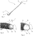
- Figures 1-3 illustrate an embodiment of a catheter 1 according to the invention.
- Figure 1 illustrates a perspective view of the catheter 1
- figure 2 illustrates a view of the catheter seen from above
- figure 3 illustrates a cross-sectional view of the catheter.
- the catheter 1 has a proximal insertion end 2 and a distal end 3.
- the catheter is provided with a rounded tip 4 and in the distal end 3, the catheter is provided with a connector 5. Furthermore, there is at least one eyelet 6 near the proximal end 2 of the catheter. From figure 2 and 3 it appears that the cross-section of the catheter is generally triangular with three substantially flat surfaces 7a , 7b , 7c connected by rounded corners 8a , 8b , 8c . The cross-section of the catheter is hatched and the inner cross-sectional area is indicated at 9 in figure 3 .
- Figures 4 to 6 illustrate the difference between the position of the eyelets in a catheter with a generally circular cross section ( figure 5 ) and in a catheter with a generally triangular cross-section ( figure 6).
- Figure 4 illustrates an eyelet 10 seen from the front or from the face.
- the eyelet 10 is oval having a larger dimension in the longitudinal direction of the catheter and is provided with a rounded edge 11 .
- the surface of the catheter is indicated at 12 .
- the edge 11 has four major parts, top 11a and bottom 11b extending transversely of the catheter and two sides 11c , 11d , extending in the longitudinal direction of the catheter.
- Figure 5 illustrates a schematic drawing of the position of the eyelet 10 in a catheter with generally circular cross section and how the two sides 11c , 11d of the edge is positioned lower in the surface 12 than the top 11a and bottom , respectively. This positioning of the edge 11 of the eyelet may lead to chafing of the mocusal tissue inside the urethra.
- Figure 6 illustrates a schematic drawing of the position of the eyelet 10 in a catheter with generally triangular cross section. From this figure it can be seen that all four parts ( 11a , 11b , 11c and 11d ) of the edge are positioned generally at the same level with respect to the surface 12 . The dotted line indicates the rounding of the edge 11 .
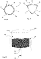
- Figures 7A and 7B illustrate partly an embodiment of a catheter 20 according to the invention, with three eyelets 21 positioned at the same height.
- Figures 8 and 9 illustrate cross sections of catheters having three eyelets at the same height.
- a catheter 30 with a circular cross section is illustrated and in figure 9 , a catheter 40 with a triangular cross section is illustrated.
- the cross-section is shown hatched and the eyelets are indicated at 31 , 32 and 33 in figure 8 and at 41 , 42 and 43 in figure 9 .
- FIG 10 illustrates the test set-up 100 used for the tests.
- the test set-up 100 includes a water tank 101 with an inlet tube 102 and an outlet tube 103 . Furthermore, an overflow tube 104 is provided.
- the outlet tube is provided with a tap 104 for opening and closing the outlet - and a rubber stopper 105 for closing the tube.
- a catheter provided with a modified rubber stopper is inserted in the outlet tube 103 in place of the rubber stopper 105 .
- the inlet tube 102 is connected to a water supply so that water continuously flows into the water tank 101 .
- the overflow tube 104 ensures that the level in the water tank is kept constant, thus ensuring that the pressure difference is constant and the correct volumetric flow through the catheter is measured.
- the tap 104 is opened and water drains through the catheter until the measurement is finished - see description in the Examples below.
- Tests were done on intermittent female catheters. As mentioned in the Background supra, females that are not catheter users are able to empty their bladder with a volumetric flow rate of 24 ml/s in average.
- a known catheter CH12 has a volumetric flow rate of about 9 ml/s in average (8.9 ml/s). This means that in average a catheter user takes up to three times as long time as a non-catheter user to empty their bladder.
- Different geometries of female catheters were tested to show which geometries influence the flow rates and by how much.
- the catheters were tested according to standard DS/EN 1618:1997. The testing was for all types of catheters done at a water column pressure of 400 mm H 2 O. The time it takes to empty 200 ml was measured.
- test set-up is shown in figure 10 .
- test series 1 to 6 The dimensions of the eyelets for test series 1 to 6 were a width (in the transverse direction of the catheter) of 0.9 mm and a height (in the longitudinal direction of the catheter) of 3.4 mm.
- the test series were as follows:
- Table 1 Test series Catheter type Mean ml/s Standard deviation 1 Triangular, ONE eyelet 19 mm from tip 8.6 0.33 2 Triangular, TWO eyelets 19 mm from tip 11.1 0.40 3 Triangular, THREE eyelets 19 mm from tip 12.5 0.51 4 Triangular, TWO eyelets, 7 mm / 19 mm from tip 10.5 0.29 5 Round, TWO eyelets, 7 mm / 19 mm from tip 10.6 0.33 6 Triangular, Conical, three eyelets CH10-->CH14 17.3 0.70 7 Triangular, Conical, three eyelets CH10 --> CH14, eyelets 20 % larger 18.9 0.26 8 Triangular, Conical, three eyelets CH10 --> CH14, eyelets 20 % smaller 15.8 0.38 9 Triangular, Conical, three
- Comparing test series 4 and 5 illustrates that by using a triangular catheter instead of a round catheter, the flow decreases slightly - however the difference is so small it is not significant. Thus, it is possible to use a triangular catheter and obtain the benefits with respect to reduced micro-traumas in the urethra due to the eyelets without influencing the flow through the catheter significantly.
- Comparing test series 1 to 3 illustrates that there is a large benefit of increasing the number of eyelets in the same height (equidistantly from the tip) from one to three.
- the flow through the catheter increases by almost 50 %. This can be explained by the theory above - that if the total area of eyelets at the same height (equidistantly from the tip) are at least as large as the cross-sectional area of the catheter, then the eyelets will not be the limiting factor with respect to flow.
- Comparing test series 3 and 6 illustrates that by making the catheter conical an increase in the flow of more than 60 % is obtained. As mentioned above, this is because the flow will be more laminar in a conical catheter and less turbulent. Laminar flow is to be aimed for since this is the fastest flow possible through a tube.
- Comparing test series 6 to 8 illustrates the influence of the width of the eyelets.
- the width of the eyelets is 20% higher, the flow is increased by almost 10%.
- a decrease in the width of the eyelets by 20% leads to a decrease in the flow by almost 10%.
- test series 7 and 9 illustrates that by increasing the width of the eyelets by 20 %, it is possible to obtain almost the same flow through the catheter as that obtainable by a suction catheter - that is a catheter having no tip and eyelets but just being cut-off at the position of the eyelets. The difference in flow between series 7 and 9 is not significant.
- the test shows that the optimal catheter with respect to flow is a triangular catheter having three eyelets in the same height and having a cross-sectional area which increases from an area corresponding to a CH10 at the tip and to a CH14 at the outlet.
Landscapes
- Health & Medical Sciences (AREA)
- Life Sciences & Earth Sciences (AREA)
- Biophysics (AREA)
- Pulmonology (AREA)
- Engineering & Computer Science (AREA)
- Anesthesiology (AREA)
- Biomedical Technology (AREA)
- Heart & Thoracic Surgery (AREA)
- Hematology (AREA)
- Animal Behavior & Ethology (AREA)
- General Health & Medical Sciences (AREA)
- Public Health (AREA)
- Veterinary Medicine (AREA)
- Epidemiology (AREA)
- Urology & Nephrology (AREA)
- External Artificial Organs (AREA)
- Media Introduction/Drainage Providing Device (AREA)
- Orthopedics, Nursing, And Contraception (AREA)
Abstract
Description
- Urinary catheter assemblies for draining the bladder are increasingly used for intermittent catheterisation. Typically, urinary catheters are used by patients suffering from urinary incontinence or by disabled individuals like paraplegics or tetraplegics, who may have no control permitting voluntary urination and for whom catheterisation may be the way of urinating.
- Intermittent catheters are typically inserted by the user him- or herself and sits only in the urethra and bladder for as long as it takes to empty the bladder - e.g. for about 5-10 minutes. Intermittent catheters are used every 4-6 hours to empty the bladder corresponding roughly to the interval at which people having no urinary problems would usually go to the bathroom. An important feature for the intermittent catheter is to ease the insertion into the urethra. This is done by providing the intermittent catheter with a low frictious surface. Non-limiting examples of such are hydrophilic coated catheters which are subsequently wetted by a swelling media in order to produce a low friction surface, or oil or water based gel which is applied to the catheter before insertion into the urethra.
- Intermittent urinary catheters may be provided with a hydrophilic coating that needs to be wetted prior to use and thereby absorbs a considerable amount of liquid. Such a hydrophilic coating will provide a very lubricious surface that has very low-friction when the catheter is to be inserted.
- Users of intermittent catheters may experience that emptying of the bladder takes long time - e.g. more than 10-15 minutes. This may at least partly be due to the fact that the user is unable to provide any pressure to the bladder, e.g. if the user is somehow spinal cord injured. This means that the urine has to exit the bladder through the catheter only through gravity forces. Furthermore, the limitation in the diameter of the catheter may also influence the flow-rate. The volumetric flow rate for a female that is not a catheter user is in average 25 ml/s - however flow rates down to 15 ml/s are within the normal margin.
- The invention relates to an intermittent urinary catheter as defined below.
-
-
Figure 1 illustrates a perspective view of an embodiment of a catheter according to the invention. -
Figure 2 illustrates a view seen from above of an embodiment of a catheter according to the invention. -
Figure 3 illustrates a cross-sectional view of an embodiment of a catheter according to the invention. -
Figures 4 to 6 illustrate the difference between the position of the eyelets in a catheter with a generally circular cross section (figure 5 ) and in a catheter with a generally triangular cross-section (figure 6 ). -
Figures 7A and 7B illustrate an embodiment of a catheter according to the invention, with three eyelets positioned at the same height. -
Figures 8 and 9 illustrate cross sections of catheters having three eyelets at the same height.Figure 8 illustrates a catheter with a circular cross section andfigure 9 illustrates a catheter with a triangular cross section. -
Figure 10 illustrates a test set-up used for the experiments. - In embodiments, the intermittent urinary catheter is generally triangular in cross-section - this allows positioning of the eyelets in substantially flat surfaces and thus reduction of chafing at the mucosal surfaces of the urethra. Another aspect of the invention relates to positioning at least two eyelets in the same height at the urinary catheter - that is equidistantly from the tip. More eyelets positioned at the same height will allow for an increase in flow because more liquid can enter into the catheter and be drained out from the bladder. An interesting embodiment relates to a conical catheter. Conical catheters will lead to a more laminar flow, which provides a better flow than a more turbulent flow.
- In a first aspect, the invention relates to an intermittent urinary catheter with a generally triangular cross-section with three substantially flat surfaces connected by rounded corners and at least one eyelet positioned in one of the surfaces.
- A catheter with a triangular cross-section has a higher buckling strength than a catheter with a round cross-section. This means that the wall thickness of the catheter can be reduced in a triangular catheter and thus a larger inner cross-sectional area can be achieved.
- Furthermore, the eyelets can be positioned in substantially flat surfaces on the sides of the catheter. When eyelets are positioned in a substantially flat surface the entire edge of the eyelet will be in the same plane - that is the plane that corresponds to the surface. When eyelets are positioned in a round surface, the edge of the eyelets will be curved in three dimensions. This means that parts of the edge, more specifically, the parts in the longitudinal direction of the catheter, will be positioned in another (lower) plane than the parts in the transverse direction of the catheter. The mucosa of the urethra may have a tendency to collapse around the catheter during insertion, thus if the edge of an eyelet is three-dimensional and thus has parts positioned lower than other parts, the mucosa may be slightly caught at the lower parts during insertion. This may lead to a degree of chafing at the mucosa during insertion. A plane or two-dimensional eyelet positioned in a substantially flat surface will minimise this effect, because there will be no lower positioned parts of the eyelet - thus the chafing caused by this will be eliminated.
- By substantially flat surfaces is meant that seen in cross section, the length of the curve defining the surface between two corners are only slightly longer (less than 15 %, or more preferred less than 10 %, such as less than 5 %) than the chord between the same two corners. In other words, the surface area of one side of the catheter is less than 15 % (such as less than 10 % or less than 5 %) larger than the area of the plane spanned by the two corners of the side.
- By rounded corners is meant that the transition from one surface to another around a circumferential cross-section of the catheter follows a rounded curve.
- Another way of describing this is that the cross-section of the catheter consists of three pieces having a first small curvature (large radius) joined alternately with three pieces having a second larger curvature (small radius). The small radius (the corners) may be between 1 mm and 1.7 mm - such as 1.4 mm or 1.5 mm, whereas the large radius may be more than 10 mm.
- In an embodiment of the invention, the three substantially flat surfaces are of generally the same size. By generally the same size is meant that the surfaces have generally the same area meaning that the variation in area between the surfaces is lower than 5%.
- In the following, whenever referring to a proximal end of an element of the invention, the referral is to the end adapted for insertion. Whenever referring to the distal end of an element, the referral is to the end opposite the insertion end. In other words, the proximal end is the end closest to the user, when the catheter is to be inserted and the distal end is the opposite end - the end furthest away from the user when the catheter is to be inserted.
- The longitudinal direction is the direction from the distal to the proximal end. The transverse direction is the direction perpendicular to the longitudinal direction, which corresponds to the direction across the shaft of the catheter.
- The catheters described in this application are adapted for use as a urinary catheter.
- The catheter comprises a main tubular part extending from the distal end to the proximal end. The tip is positioned in the proximal end of the catheter and is provided as a rounded closed end of the tube constituting the main part of the catheter. Eyelet(s) for letting urine enter into the catheter is typically positioned close to the tip. The catheter may comprise a connector in the distal end and may in an embodiment comprise a flared end of the catheter so that the diameter of the connector increases with respect to the tubular part. The catheter may also comprise a handle in the distal end, which has a length allowing the user to manipulate the catheter.
- Usually catheters used as urinary draining devices and adapted for intermittently being inserted into the urethra to drain urine from the bladder, are from size 8 FR to size 18 FR. FR (or French size or Charriere (Ch)) is a standard gauge for catheters approximately corresponding to the outer circumference in mm. More accurately, the outer diameter of the catheter in mm corresponds to FR divided by 3. Thus 8 FR corresponds to a catheter with an outer diameter of 2.7 mm and 18 FR corresponds to a catheter with an outer diameter of 6 mm.
- A catheter used as urinary draining devices (a urinary catheter) which is adapted for intermittently being inserted into the urethra to drain urine from the bladder is adapted for being inserted by the user him/herself without assistance from medical personal and without insertion of any type of aids (e.g. guidewires) prior to insertion of the urinary catheter.
- The eyelets may have an area at the surface of the catheter of between 3-5 mm2.
- For the triangular catheters of this invention, the correlation between the CH sizes and the triangular catheters is so that the cross-sectional area inside the catheter corresponds to the cross-sectional area inside the corresponding CH size. Thus the CH size corresponds neither to the inscribed circle of the triangle nor to the circumscribed circle of the triangle. Rather comparing the triangular cross-section with the corresponding CH size, the CH size is between the inscribed circle and the circumscribed circle of the triangle.
- The circumference of a triangular catheter is defined (the usual way) as the sum of the side lengths in the cross-section.
- Catheters of this invention may prior to use be provided with a hydrophilic coating so as to impart a low-friction insertion.
- The hydrophilic coating may be provided only on the insertable part of the catheter. The hydrophilic surface coating is of the kind which, when hydrated or swelled using a swelling medium, reduces the friction on the surface area of the catheter which is intended to be inserted into the urinary channel of a user corresponding to the insertable part of the catheter.
- An intermittent hydrophilic catheter differs from an indwelling catheter in that the hydrophilic surface coating of such a catheter is not suitable for indwelling use, because the surface coating tends to stick inside the mucosa of the urethra if left inside the body for a period exceeding 5-20 minutes, due to the hydrophilic coating transforming from being highly lubricious when fully wetted (95% weight water) to being adhesive when the hydration level of the coating is reduced (<75% weight water).
- In a second aspect, the invention relates to an intermittent, urinary catheter, where the catheter is provided with two eyelets positioned equidistantly from the tip of the catheter.
- Eyelets positioned equidistantly from the tip are an advantage, because the urine will flow where the resistance is lowest meaning that urine would rather flow in the bladder than flow inside the catheter due to the lower resistance in the bladder than in the catheter. This means that if the eyelets were positioned with a different distance to the tip, then the eyelet closer to the tip would contribute less than the eyelet furthest from the tip - provided that the lowermost eyelet is inserted fully into the bladder so urine can flow freely into this eyelet. In other words, the urine will mostly run through the eyelets closest to the outlet to avoid the higher resistance inside the catheter for as long as possible.
- Thus, positioning of two eyelets with the same distance to the tip ensures that both eyelets will contribute to lead the urine into the catheter.
- In an embodiment, the catheter is provided with three eyelets positioned equidistantly from the tip of the catheter.
- Three eyelets will provide for an even better emptying of the bladder.
- Increasing the total area of the eyelets (the sum of the areas of each eyelet) will lead to an increased inflow of urine into the catheter. However, the catheter is only able to drain as much urine as the cross-sectional area of the catheter allows. This is because the volumetric flow rate follows the following principle:
The resistance equals the pressure difference divided by the volumetric flow rate. - The above can be expressed in the form of an equation:

- In the equation above, R is the resistance to flow, ΔP is the pressure difference, Q is the volumetric flow rate, µ is the fluid viscosity, L is the length and a is the cross-sectional area.
- Thus the volumetric flow rate Q can be expressed as:

- From the equation above, it is clear that the cross-sectional area has a great influence on the volumetric flow rate. Thus, the cross-sectional area is the main factor on how fast the urine can be drained through the catheter.
- This means that if the total area of the eyelets can be as large as (or even exceed) the cross-sectional area of the catheter at the eyelets, then the cross-sectional area is utilised to the optimum degree.
- Due to the above consideration relating to urine flowing where the resistance is as small as possible, it is most beneficiary to increase the width of the eyelets (transversely of the catheter) rather than increasing the length of the eyelets (longitudinally of the catheter). This is because increasing the width provides for the direct inflow into the catheter at a lower point than increasing the length.
- In an embodiment of the invention, the first aspect is combined with the second aspect, so the invention provides an intermittent urinary catheter having a generally triangular cross-section with three substantially flat surfaces connected by rounded corners and two eyelets positioned equidistantly from the tip in two of the surfaces.
- In a further embodiment, three eyelets may be positioned equidistantly from the tip, one eyelet in each of the three substantially flat surfaces.
- The triangular cross-section provides for the possibility of positioning the eyelets so they are not opposite each other. In other words, the eyelets are positioned with an angle different from 180 degrees between each other around the circumference of the catheter cross-section. Positioning of two eyelets directly opposite each other may lead to weakening of the cross-section of the catheter at the eyelets. Thus, the catheter may have a tendency to collapse at this point during insertion.
- By positioning the eyelets with an angle of approximately 120 degrees between around the circumference, this effect is avoided.
- In an embodiment of the invention, the catheter is conical so that the inner cross-sectional area increases from the proximal insertion end to the distal end. In a related embodiment, the cross-sectional area increases corresponding to at least one CH size.
- By increasing the cross-sectional area at least one CH size, the degree of laminar flow with respect to turbulent flow inside the catheter will increase. Laminar flow is the fastest possible flow through a tube, thus it is desirable to achieve a high degree of laminar flow through the catheter.
- In a related embodiment, the cross-sectional area increases corresponding to at least two CH sizes. In an example, the insertion end has a cross-sectional area corresponding to a CH10 and the distal end has a cross-sectional area corresponding to a CH14.
- A further advantage of a conical catheter is that users may have to use a rather thin catheter (CH8 or CH10) for various reasons (e.g. narrow passage around the prostate) and previously had to live with the increased drainage time that was the effect of that. With a conical catheter this drawback is eliminated because the user can use a catheter having a CH10 as the insertion end and a CH14 as the distal end - and thus experience a flow corresponding to a regular CH14.
- A third aspect of the invention relates to an intermittent urinary catheter having a volumetric flow of at least 15 ml/s when measured at a pressure of 400 mm H2O.
- The measurement of the volumetric flow is performed according to the standard DS/EN 1618:1997. Instead of measuring for at least 30 s as mentioned in the standard, the time to empty 200 ml were used. The catheter is attached to a constant level tank by attaching it in a central hole in a rubber stopper attached to a plastic tube that in turn is attached to a tapered connector on the constant level tank.
- As mentioned in the Background supra, pressures of 400 mm H2O are normal for a user who is about to empty his or her bladder. With a volumetric flow of at least 15 ml/s, a catheter user will be able to empty the bladder as fast as a non-catheter user, because this flow is within the normal range of emptying for women.
- Initially, it shall be noted that the figures are schematic illustrations intended only to address the principles and functions of the base plate according to the invention and are not to be considered limiting to the scope of the attached claims. Furthermore, the figures and particularly the individually illustrated elements are not necessarily to scale, neither individually nor in relation to each other.
-
Figures 1-3 illustrate an embodiment of acatheter 1 according to the invention.Figure 1 illustrates a perspective view of thecatheter 1,figure 2 illustrates a view of the catheter seen from above andfigure 3 illustrates a cross-sectional view of the catheter. - The
catheter 1 has aproximal insertion end 2 and adistal end 3. In theproximal end 2, the catheter is provided with arounded tip 4 and in thedistal end 3, the catheter is provided with aconnector 5. Furthermore, there is at least one eyelet 6 near theproximal end 2 of the catheter. Fromfigure 2 and 3 it appears that the cross-section of the catheter is generally triangular with three substantiallyflat surfaces rounded corners figure 3 . -
Figures 4 to 6 illustrate the difference between the position of the eyelets in a catheter with a generally circular cross section (figure 5 ) and in a catheter with a generally triangular cross-section (figure 6). Figure 4 illustrates aneyelet 10 seen from the front or from the face. As can be seen infigure 4 , theeyelet 10 is oval having a larger dimension in the longitudinal direction of the catheter and is provided with arounded edge 11. The surface of the catheter is indicated at 12. Theedge 11 has four major parts, top 11a and bottom 11b extending transversely of the catheter and twosides -
Figure 5 illustrates a schematic drawing of the position of theeyelet 10 in a catheter with generally circular cross section and how the twosides surface 12 than the top 11a and bottom , respectively. This positioning of theedge 11 of the eyelet may lead to chafing of the mocusal tissue inside the urethra. -
Figure 6 illustrates a schematic drawing of the position of theeyelet 10 in a catheter with generally triangular cross section. From this figure it can be seen that all four parts (11a, 11b, 11c and 11d) of the edge are positioned generally at the same level with respect to thesurface 12. The dotted line indicates the rounding of theedge 11. -
Figures 7A and 7B illustrate partly an embodiment of acatheter 20 according to the invention, with threeeyelets 21 positioned at the same height.Figures 8 and 9 illustrate cross sections of catheters having three eyelets at the same height. Infigure 8 , acatheter 30 with a circular cross section is illustrated and infigure 9 , acatheter 40 with a triangular cross section is illustrated. The cross-section is shown hatched and the eyelets are indicated at 31, 32 and 33 infigure 8 and at 41, 42 and 43 infigure 9 . From the figures, it is clear that in thetriangular catheter 40, the material left at the cross-section, indicated at 44, 45 and 46, will provide for triangular structures, whereas in the circular catheter, the material left at the cross section, indicated at 34, 35 and 36 will provide for arcuate structures. Triangular structures are the strongest possible structures because of the inability of the parts of the triangle to move with respect to each other. Therefore, the structure infigure 9 will be much stronger than the structure infigure 8 and thus a catheter having a cross-section as shown infigure 9 will be able to withstand buckling better than a catheter having a cross-section as shown infigure 8 . -
Figure 10 illustrates the test set-up 100 used for the tests. The test set-up 100 includes awater tank 101 with aninlet tube 102 and anoutlet tube 103. Furthermore, anoverflow tube 104 is provided. The outlet tube is provided with atap 104 for opening and closing the outlet - and arubber stopper 105 for closing the tube. In use, a catheter provided with a modified rubber stopper is inserted in theoutlet tube 103 in place of therubber stopper 105. Theinlet tube 102 is connected to a water supply so that water continuously flows into thewater tank 101. Theoverflow tube 104 ensures that the level in the water tank is kept constant, thus ensuring that the pressure difference is constant and the correct volumetric flow through the catheter is measured. Thetap 104 is opened and water drains through the catheter until the measurement is finished - see description in the Examples below. - Tests were done on intermittent female catheters. As mentioned in the Background supra, females that are not catheter users are able to empty their bladder with a volumetric flow rate of 24 ml/s in average. A known catheter CH12 has a volumetric flow rate of about 9 ml/s in average (8.9 ml/s). This means that in average a catheter user takes up to three times as long time as a non-catheter user to empty their bladder. Different geometries of female catheters were tested to show which geometries influence the flow rates and by how much.
- The catheters were tested according to standard DS/EN 1618:1997. The testing was for all types of catheters done at a water column pressure of 400 mm H2O. The time it takes to empty 200 ml was measured.
- The test set-up is shown in
figure 10 . - For all
tests 5 measurements were done on each catheter, as described in the process for testing below: - 1. Insert a rubber stopper with a centre hole corresponding largely to the circumference of the catheters to be tested in a 24 cm plastic tube.
- 2. Connect the plastic tube to the constant level tank and let the water flow through the tube for a couple of seconds, then close the valve.
- 3. Insert a test catheter through the stopper, and start the water flow. Control that the inlet still maintains a constant level while draining, if not increase the inflow. Repeat until the correct inflow is observed.
- 4. Align the plastic tube fitting at the constant level tank, so that the correct water column pressure is obtained: 400 mm from water surface to bottom of the lower edge of the lower eyelet of the catheter.
- 5. Turn on the water faucet and fill the water tank so the constant level is placed at the overflow channel and maintain the filling. Measure the distance from the water surface to the lower eye and adjust the plastic tube so that a distance of exactly 400 mm from water surface to lower edge of lower eyelet of the catheter is obtained.
- 6. Pull out the test catheter.
- 7. Insert a catheter to be tested.
- 8. Put a finger under the plunger and the open the valve. Eliminate air bubbles in the tube and valve by snapping at the plastic tube and faucet. Close the valve and remove the finger.
- 9. Start the stopwatch simultaneously with opening the valve.
- 10. When the water reaches 200 ml in the measuring cylinder close the valve and stop the stopwatch.
- 11. Place the filled measuring cylinder on a scale; subtract the weight of the empty measuring cylinder to obtain a more precise measure of how much water passed through. Take the amount of water in ml (1ml=1g) and divide it by the time you measured on the stop watch. Write down how many ml/s ran through.
- 12. Empty the measuring cylinder and shake it a couple of times to remove excess water, and pull out the catheter tip and shake a couple of times.
- 13. Repeat step # 7-12 until there are 5 measurements for the catheter.
- All tested catheters were 3D-printed using a printer called ProJet HD 3000 plus from 3DSystems and material called VisiJet EX200. Initial tests shown that the flow through the catheter may increase by 15 % by using printed catheters as opposed to regular catheters (10.5 ml/s for a printed CH12 catheter compared to 8.9 ml/s for a regular CH12 female catheter). This is thought to be due to the surface structure.
- The dimensions of the eyelets for
test series 1 to 6 were a width (in the transverse direction of the catheter) of 0.9 mm and a height (in the longitudinal direction of the catheter) of 3.4 mm. The test series were as follows: - Series 1: 2 x triangular catheter with one eyelet. The eyelet is positioned with the center 19 mm from the tip.
- Series 2: 2 x triangular catheter with two eyelets positioned with the center 19 mm from the tip.
- Series 3: 2 x triangular catheter with three eyelets, one on each side, all positioned with the center 19 mm from the tip
- Series 4: 2 x triangular catheter with two eyelets, one eyelet positioned with the center 19 mm from the tip and one eyelet positioned with center 7 mm from the tip.
- Series 5: 2 x round catheter with two eyelets. One eyelet positioned with the center 19 mm from the tip and one eyelet positioned with the center 7 mm from the tip.
- Series 6: 2 x triangular catheter with three eyelets, placed exactly as the one described above. Conical with a cross-sectional area of a CH10 at the tip, and a CH14 at the outlet.
- Series 7: 2 x triangular catheter with three eyelets, placed exactly as the one described above. Conical with a cross-sectional area of a CH10 at the tip, and a CH14 at the outlet. The width of the eyelets is increased by 20 % with respect to series 6 (width of eyelets 1.1 mm).
- Series 8: 2 x triangular catheter with three eyelets, placed exactly as the one described above. Conical with a cross-sectional area of a CH10 at the tip, and a CH14 at the outlet. The width of the eyelets is decreased by 20 % with respect to series 6 (width of eyelets 0.72 mm).
- Series 9: 2 x triangular catheter cut-off below the eyelets to create direct inflow into the catheter tube. Conical with a cross-sectional area of a CH10 at the tip, and a CH14 at the outlet.
- The results of testing are shown in the table below. The mean-value for the series corresponds to the mean of
testing 2 catheters, each tested 5 times as described above. Thus, the mean value is the mean of 10 tests.Table 1 Test series Catheter type: Mean ml/s Standard deviation 1 Triangular, ONE eyelet 19 mm from tip 8.6 0.33 2 Triangular, TWO eyelets 19 mm from tip 11.1 0.40 3 Triangular, THREE eyelets 19 mm from tip 12.5 0.51 4 Triangular, TWO eyelets, 7 mm / 19 mm from tip 10.5 0.29 5 Round, TWO eyelets, 7 mm / 19 mm from tip 10.6 0.33 6 Triangular, Conical, three eyelets CH10-->CH14 17.3 0.70 7 Triangular, Conical, three eyelets CH10 --> CH14, eyelets 20 % larger 18.9 0.26 8 Triangular, Conical, three eyelets CH10 --> CH14, eyelets 20 % smaller 15.8 0.38 9 Triangular, Conical, three eyelets CH10 --> CH14, suction 19.3 0.58 - Comparing
test series - Comparing
test series 1 to 3 illustrates that there is a large benefit of increasing the number of eyelets in the same height (equidistantly from the tip) from one to three. The flow through the catheter increases by almost 50 %. This can be explained by the theory above - that if the total area of eyelets at the same height (equidistantly from the tip) are at least as large as the cross-sectional area of the catheter, then the eyelets will not be the limiting factor with respect to flow. - Comparing
test series 3 and 6 illustrates that by making the catheter conical an increase in the flow of more than 60 % is obtained. As mentioned above, this is because the flow will be more laminar in a conical catheter and less turbulent. Laminar flow is to be aimed for since this is the fastest flow possible through a tube. - Comparing test series 6 to 8 illustrates the influence of the width of the eyelets. When the width of the eyelets is 20% higher, the flow is increased by almost 10%. Likewise a decrease in the width of the eyelets by 20% leads to a decrease in the flow by almost 10%.
- Finally comparing
test series 7 and 9 illustrates that by increasing the width of the eyelets by 20 %, it is possible to obtain almost the same flow through the catheter as that obtainable by a suction catheter - that is a catheter having no tip and eyelets but just being cut-off at the position of the eyelets. The difference in flow betweenseries 7 and 9 is not significant. - In conclusion, the test shows that the optimal catheter with respect to flow is a triangular catheter having three eyelets in the same height and having a cross-sectional area which increases from an area corresponding to a CH10 at the tip and to a CH14 at the outlet. Even if the results were reduced by 15 % to compensate for the possible influence in material difference (printed material vs. regular catheter material), a catheter as in series 7 (reduced by 15 % --> flow = 16.1 ml/s) would still provide a flow within the region of flows for non-catheter users. Thus, a catheter user should be able to empty their bladder as fast as a non-catheter user.
-
- 1. An intermittent urinary catheter with a generally triangular cross-section with three substantially flat surfaces connected by rounded corners and at least one eyelet positioned in one of the surfaces.
- 2. The intermittent urinary catheter according to
embodiment 1, wherein the three substantially flat surfaces are of generally the same size. - 3. An intermittent, urinary catheter, where the catheter is provided with at least two eyelets positioned equidistantly from the tip of the catheter.
- 4. The intermittent, urinary catheter according to
embodiment 3, wherein the catheter is provided with three eyelets positioned equidistantly from the tip of the catheter. - 5. The intermittent urinary catheter according to any of embodiments 1-2, wherein the catheter is provided with two eyelets positioned equidistantly from the tip.
- 6. The intermittent urinary catheter according to any of embodiments 1-2, wherein the catheter is provided with three eyelets positioned equidistantly from the tip.
- 7. The intermittent urinary catheter according to embodiment 6 wherein the three eyelets are positioned so that one eyelet is positioned in each of the three substantially flat surfaces.
- 8. The intermittent urinary catheter according to any of the preceding embodiments, wherein the catheter is conical so that the inner cross-sectional area increases from the proximal insertion end to the distal end.
- 9. The intermittent urinary catheter according to embodiment 8, wherein the increase in cross-sectional area from the proximal end to the distal end corresponds to at least one, preferably two CH sizes.
- 10. An intermittent urinary catheter having a flow through the catheter of at least 15 ml/s when measured at a pressure of 400 mm H2O.
Claims (9)
- An intermittent, urinary catheter, where the catheter is provided with at least two eyelets positioned equidistantly from the tip of the catheter.
- The intermittent, urinary catheter according to claim 1, wherein the catheter is provided with three eyelets positioned equidistantly from the tip of the catheter.
- The intermittent urinary catheter according to any of the preceding claims, wherein the catheter is conical so that the inner cross-sectional area increases from the proximal insertion end to the distal end.
- The intermittent urinary catheter according to claim 3, wherein the increase in cross-sectional area from the proximal end to the distal end corresponds to at least one, preferably two CH sizes.
- The intermittent urinary catheter according to any of claims 3 or 4, wherein the proximal insertion end has a cross-sectional area corresponding to a CH10 and the distal end has a cross-sectional area corresponding to a CH14.
- The intermittent urinary catheter according to any of the preceding claims, wherein the eyelets have an area at the surface of the catheter of between 3-5 mm2.
- The intermittent urinary catheter according to any of the preceding claims, wherein the total area of the eyelets is at least as large as the cross-sectional area of the catheter at the eyelets.
- The intermittent urinary catheter according to any of the preceding claims, wherein the catheter is provided with a hydrophilic coating.
- The intermittent urinary catheter according to any of the preceding claims, wherein the catheter is having a flow through the catheter of at least 15 ml/s when measured at a pressure of 400 mm H2O.
Applications Claiming Priority (3)
| Application Number | Priority Date | Filing Date | Title |
|---|---|---|---|
| DKPA201370808 | 2013-12-20 | ||
| EP14825260.4A EP3082929B1 (en) | 2013-12-20 | 2014-12-19 | An intermittent urinary catheter |
| PCT/DK2014/050445 WO2015090338A1 (en) | 2013-12-20 | 2014-12-19 | An intermittent urinary catheter |
Related Parent Applications (1)
| Application Number | Title | Priority Date | Filing Date |
|---|---|---|---|
| EP14825260.4A Division EP3082929B1 (en) | 2013-12-20 | 2014-12-19 | An intermittent urinary catheter |
Publications (1)
| Publication Number | Publication Date |
|---|---|
| EP4101492A1 true EP4101492A1 (en) | 2022-12-14 |
Family
ID=50112655
Family Applications (2)
| Application Number | Title | Priority Date | Filing Date |
|---|---|---|---|
| EP14825260.4A Active EP3082929B1 (en) | 2013-12-20 | 2014-12-19 | An intermittent urinary catheter |
| EP22164302.6A Pending EP4101492A1 (en) | 2013-12-20 | 2014-12-19 | An intermittent urinary catheter |
Family Applications Before (1)
| Application Number | Title | Priority Date | Filing Date |
|---|---|---|---|
| EP14825260.4A Active EP3082929B1 (en) | 2013-12-20 | 2014-12-19 | An intermittent urinary catheter |
Country Status (6)
| Country | Link |
|---|---|
| US (2) | US10493230B2 (en) |
| EP (2) | EP3082929B1 (en) |
| CN (1) | CN105828864B (en) |
| BR (1) | BR112016013510A2 (en) |
| RU (2) | RU2699741C1 (en) |
| WO (1) | WO2015090338A1 (en) |
Cited By (3)
| Publication number | Priority date | Publication date | Assignee | Title |
|---|---|---|---|---|
| US12011547B2 (en) | 2020-04-24 | 2024-06-18 | Convatec Limited | Wetting mechanism for a catheter |
| US12053593B2 (en) | 2020-04-24 | 2024-08-06 | Convatec Limited | Wetting mechanism for a catheter |
| US12171956B2 (en) | 2020-04-24 | 2024-12-24 | Convatec Limited | Wetting mechanism for a catheter |
Families Citing this family (29)
| Publication number | Priority date | Publication date | Assignee | Title |
|---|---|---|---|---|
| MX348673B (en) | 2008-05-01 | 2017-06-23 | Convatec Tech Inc * | Rectal drain appliance. |
| CN103533969A (en) | 2011-03-17 | 2014-01-22 | 康沃特克科技公司 | High barrier elastomer fecal catheter or ostomy bag |
| CA2918607C (en) | 2013-08-01 | 2024-02-20 | Convatec Technologies Inc. | Self-closing bag connector |
| CA2957085C (en) | 2014-08-26 | 2023-01-17 | C.R. Bard, Inc. | Packaging and hydrophilic coating of urinary catheter |
| IL254838A0 (en) | 2016-10-05 | 2017-12-31 | Cathaway Medical 2012 Ltd | Asymmetric catheter tips |
| WO2018198837A1 (en) | 2017-04-28 | 2018-11-01 | 株式会社Screenホールディングス | Anastomosis assisting tool and vascular anastomosis method |
| JP6430673B2 (en) * | 2017-04-28 | 2018-11-28 | 株式会社Screenホールディングス | Anastomosis aid |
| MX2020004744A (en) | 2017-11-09 | 2020-08-13 | 11 Health And Tech Limited | Ostomy monitoring system and method. |
| GB201721955D0 (en) | 2017-12-27 | 2018-02-07 | Convatec Ltd | Catheter wetting devices |
| GB201721956D0 (en) | 2017-12-27 | 2018-02-07 | Convatec Ltd | Female catheter locator tip |
| CN112312951A (en) | 2018-04-12 | 2021-02-02 | 火箭科学健康公司 | Intranasal drug delivery devices, systems and procedures |
| USD893514S1 (en) | 2018-11-08 | 2020-08-18 | 11 Health And Technologies Limited | Display screen or portion thereof with graphical user interface |
| MX2021005900A (en) * | 2018-11-21 | 2021-08-11 | Coloplast As | An intermittent urinary catheter. |
| CN116271420B (en) * | 2019-02-08 | 2025-11-21 | 科洛普拉斯特公司 | Urinary catheter |
| AU2020290905A1 (en) | 2019-06-11 | 2021-11-18 | Convatec Technologies Inc. | Urine collection bags for use with catheter products, kits incorporating the same, and methods therefor |
| RU2737217C1 (en) * | 2019-10-08 | 2020-11-26 | Александр Анатольевич Зимичев | Method of low-traumatic installation of urethral catheter |
| USD975844S1 (en) | 2019-11-06 | 2023-01-17 | Free Life Medical Gmbh | Cannula |
| EP4364777B1 (en) | 2020-08-03 | 2026-05-06 | C. R. Bard, Inc. | Intermittent-catheter assemblies and methods thereof |
| US12611519B2 (en) | 2020-09-11 | 2026-04-28 | C. R. Bard, Inc. | Intermittent-catheter assembly and methods thereof |
| AU2021361238A1 (en) | 2020-10-15 | 2023-05-25 | Convatec Technologies Inc. | Ostomy systems and methods |
| USD967404S1 (en) | 2021-04-16 | 2022-10-18 | Hollister Incorporated | Urinary catheter |
| USD967406S1 (en) | 2021-04-16 | 2022-10-18 | Hollister Incorporated | Urinary catheter |
| USD967405S1 (en) | 2021-04-16 | 2022-10-18 | Hollister Incorporated | Urinary catheter |
| USD967403S1 (en) | 2021-04-16 | 2022-10-18 | Hollister Incorporated | Urinary catheter |
| USD967407S1 (en) | 2021-04-16 | 2022-10-18 | Hollister Incorporated | Urinary catheter |
| USD1083086S1 (en) | 2022-12-20 | 2025-07-08 | Hollister Incorporated | Intermittent urinary catheter |
| EP4709456A1 (en) * | 2023-05-09 | 2026-03-18 | Hollister Incorporated | Urinary catheter products with increased lubricity |
| US20250161627A1 (en) | 2023-10-27 | 2025-05-22 | Nowwell Flow Technology AS | Catheter |
| USD1103378S1 (en) | 2024-05-29 | 2025-11-25 | Hollister Incorporated | Intermittent urinary catheter |
Citations (5)
| Publication number | Priority date | Publication date | Assignee | Title |
|---|---|---|---|---|
| RU2008031C1 (en) * | 1991-02-13 | 1994-02-28 | Александр Робертович Гуськов | Catheter |
| US20030216710A1 (en) * | 2002-03-26 | 2003-11-20 | Hurt Robert F. | Catheter |
| US20090221992A1 (en) * | 2008-02-28 | 2009-09-03 | Hollister Incorporated | Fluid Drainage Catheter Having an External Flow Path |
| WO2011014201A1 (en) * | 2009-07-29 | 2011-02-03 | C. R. Bard, Inc. | Catheter having improved drainage and/or a retractable sleeve and method of using the same |
| US20120239005A1 (en) * | 2011-03-14 | 2012-09-20 | Conway Anthony J | Catheter grip and method |
Family Cites Families (15)
| Publication number | Priority date | Publication date | Assignee | Title |
|---|---|---|---|---|
| US3831814A (en) * | 1969-07-25 | 1974-08-27 | Cutter Lab | Trocar-cannula |
| US4406656A (en) * | 1981-06-01 | 1983-09-27 | Brack Gillium Hattler | Venous catheter having collapsible multi-lumens |
| US4894057A (en) | 1987-06-19 | 1990-01-16 | Howes Randolph M | Flow enhanced multi-lumen venous catheter device |
| US5368566A (en) * | 1992-04-29 | 1994-11-29 | Cardiovascular Dynamics, Inc. | Delivery and temporary stent catheter having a reinforced perfusion lumen |
| US5947953A (en) * | 1997-08-06 | 1999-09-07 | Hemocleanse, Inc. | Splittable multiple catheter assembly and methods of inserting the same |
| AU733053C (en) * | 1998-02-24 | 2001-11-29 | Boston Scientific Limited | High flow rate dialysis catheters and related methods |
| US7331949B2 (en) * | 2003-02-27 | 2008-02-19 | Margaret Grahn Marisi | Urinary catheter with check valve |
| GB2418361A (en) | 2004-08-13 | 2006-03-29 | Don Julian De Silva | Intravenous catheter with flow increase |
| US7879053B2 (en) * | 2004-12-20 | 2011-02-01 | Boston Scientific Scimed, Inc. | Balloon with stepped sections and implements |
| DE102006052612B3 (en) | 2006-06-07 | 2008-02-07 | Mykhaylo Mosenkis | Implantable catheter for use in e.g. surgery, has cylindrical unit with openings extending from flat sections with groove-like recess at outer surface of unit to inner area surface, where passages from outer surface to sections are rounded |
| EP2180914A1 (en) | 2007-07-16 | 2010-05-05 | Med-I-Dynamix Fluid Monitoring Ltd. | Systems and methods for removal of urine |
| US20110319902A1 (en) * | 2010-06-26 | 2011-12-29 | Scott Epstein | Catheter delivery system |
| WO2012166168A1 (en) * | 2011-06-02 | 2012-12-06 | Atrium Medical Corporation | Body lumen fluid delivery device |
| CN202277602U (en) * | 2011-06-30 | 2012-06-20 | 南通伊诺精密塑胶导管有限公司 | Triangular prism pigtail catheter |
| US20130253479A1 (en) * | 2012-03-23 | 2013-09-26 | Tsung-chow SU | Modified flow catheters and methods of use thereof |
-
2014
- 2014-12-19 RU RU2016128060A patent/RU2699741C1/en active
- 2014-12-19 RU RU2019127382A patent/RU2019127382A/en unknown
- 2014-12-19 US US15/104,981 patent/US10493230B2/en active Active
- 2014-12-19 BR BR112016013510A patent/BR112016013510A2/en active Search and Examination
- 2014-12-19 EP EP14825260.4A patent/EP3082929B1/en active Active
- 2014-12-19 EP EP22164302.6A patent/EP4101492A1/en active Pending
- 2014-12-19 WO PCT/DK2014/050445 patent/WO2015090338A1/en not_active Ceased
- 2014-12-19 CN CN201480069549.4A patent/CN105828864B/en active Active
-
2019
- 2019-10-30 US US16/667,940 patent/US20200061335A1/en not_active Abandoned
Patent Citations (5)
| Publication number | Priority date | Publication date | Assignee | Title |
|---|---|---|---|---|
| RU2008031C1 (en) * | 1991-02-13 | 1994-02-28 | Александр Робертович Гуськов | Catheter |
| US20030216710A1 (en) * | 2002-03-26 | 2003-11-20 | Hurt Robert F. | Catheter |
| US20090221992A1 (en) * | 2008-02-28 | 2009-09-03 | Hollister Incorporated | Fluid Drainage Catheter Having an External Flow Path |
| WO2011014201A1 (en) * | 2009-07-29 | 2011-02-03 | C. R. Bard, Inc. | Catheter having improved drainage and/or a retractable sleeve and method of using the same |
| US20120239005A1 (en) * | 2011-03-14 | 2012-09-20 | Conway Anthony J | Catheter grip and method |
Cited By (3)
| Publication number | Priority date | Publication date | Assignee | Title |
|---|---|---|---|---|
| US12011547B2 (en) | 2020-04-24 | 2024-06-18 | Convatec Limited | Wetting mechanism for a catheter |
| US12053593B2 (en) | 2020-04-24 | 2024-08-06 | Convatec Limited | Wetting mechanism for a catheter |
| US12171956B2 (en) | 2020-04-24 | 2024-12-24 | Convatec Limited | Wetting mechanism for a catheter |
Also Published As
| Publication number | Publication date |
|---|---|
| RU2699741C1 (en) | 2019-09-09 |
| US10493230B2 (en) | 2019-12-03 |
| EP3082929A1 (en) | 2016-10-26 |
| CN105828864A (en) | 2016-08-03 |
| EP3082929B1 (en) | 2022-03-30 |
| RU2019127382A (en) | 2019-09-11 |
| WO2015090338A1 (en) | 2015-06-25 |
| RU2016128060A (en) | 2018-01-25 |
| CN105828864B (en) | 2020-02-14 |
| US20170028168A1 (en) | 2017-02-02 |
| US20200061335A1 (en) | 2020-02-27 |
| BR112016013510A2 (en) | 2017-08-08 |
Similar Documents
| Publication | Publication Date | Title |
|---|---|---|
| EP3082929B1 (en) | An intermittent urinary catheter | |
| US11896785B2 (en) | Ureteral and bladder catheters and methods of inducing negative pressure to increase renal perfusion | |
| US20250152783A1 (en) | Intermittent urinary catheter having multiple drainage openings | |
| EP3883630B1 (en) | An intermittent urinary catheter | |
| US6908447B2 (en) | Anti-reflux ureteral stents and methods | |
| EP3672656B1 (en) | Ureteral and bladder catheters and methods of inducing negative pressure to increase renal perfusion | |
| JPH08500982A (en) | Urinary incontinence woman and its use | |
| EP3038689B1 (en) | Catheter | |
| EP2788068A1 (en) | Liquid stop | |
| US8491569B1 (en) | Intermittent catheter | |
| JP7242688B2 (en) | urodynamic tester | |
| CN221618067U (en) | Anti-blockage ventricular drainage device | |
| CN203970988U (en) | A kind of ventricles of the brain-abdominal cavity shunt device of cerebrospinal fluid | |
| JP2018527131A (en) | A catheter-free adapter for injecting a drug from the urethra to the bladder and a method for manufacturing the device | |
| US20120004645A1 (en) | Capsular urinary catheter | |
| CN202173621U (en) | Combination type self-help catheterization device component | |
| JP7158792B1 (en) | Continuous outflow system circuit and its quality control system | |
| CN205215917U (en) | Ventricles of brain venous sinus diverging device | |
| Lee et al. | Does size matter? Measured and modeled effects of suprapubic catheter size on urinary flow | |
| CN118541186A (en) | Adjustable flow catheter | |
| CN116531585B (en) | Catheterization system | |
| CN219167237U (en) | Disposable lumbar cistern Guan Kang reflux drainage control device | |
| CN222585152U (en) | Lumbar cistern drainage device capable of locating the position of intraspinal drainage tube | |
| CN215194157U (en) | A Drainage Device That Can Flush and Easily Monitor Intra-abdominal Pressure | |
| CN219558425U (en) | Ultrafine Silicone Catheter |
Legal Events
| Date | Code | Title | Description |
|---|---|---|---|
| PUAI | Public reference made under article 153(3) epc to a published international application that has entered the european phase |
Free format text: ORIGINAL CODE: 0009012 |
|
| STAA | Information on the status of an ep patent application or granted ep patent |
Free format text: STATUS: THE APPLICATION HAS BEEN PUBLISHED |
|
| AC | Divisional application: reference to earlier application |
Ref document number: 3082929 Country of ref document: EP Kind code of ref document: P |
|
| AK | Designated contracting states |
Kind code of ref document: A1 Designated state(s): AL AT BE BG CH CY CZ DE DK EE ES FI FR GB GR HR HU IE IS IT LI LT LU LV MC MK MT NL NO PL PT RO RS SE SI SK SM TR |
|
| STAA | Information on the status of an ep patent application or granted ep patent |
Free format text: STATUS: REQUEST FOR EXAMINATION WAS MADE |
|
| 17P | Request for examination filed |
Effective date: 20230614 |
|
| RBV | Designated contracting states (corrected) |
Designated state(s): AL AT BE BG CH CY CZ DE DK EE ES FI FR GB GR HR HU IE IS IT LI LT LU LV MC MK MT NL NO PL PT RO RS SE SI SK SM TR |
|
| STAA | Information on the status of an ep patent application or granted ep patent |
Free format text: STATUS: EXAMINATION IS IN PROGRESS |
|
| 17Q | First examination report despatched |
Effective date: 20251021 |