EP4101099B1 - Gleichzeitige rückkopplungsinformation und gemeinsam genutzte uplink-kanalübertragungen - Google Patents
Gleichzeitige rückkopplungsinformation und gemeinsam genutzte uplink-kanalübertragungen Download PDFInfo
- Publication number
- EP4101099B1 EP4101099B1 EP21708823.6A EP21708823A EP4101099B1 EP 4101099 B1 EP4101099 B1 EP 4101099B1 EP 21708823 A EP21708823 A EP 21708823A EP 4101099 B1 EP4101099 B1 EP 4101099B1
- Authority
- EP
- European Patent Office
- Prior art keywords
- uplink
- carrier
- shared channel
- carriers
- transmission
- Prior art date
- Legal status (The legal status is an assumption and is not a legal conclusion. Google has not performed a legal analysis and makes no representation as to the accuracy of the status listed.)
- Active
Links
Images


Classifications
-
- H—ELECTRICITY
- H04—ELECTRIC COMMUNICATION TECHNIQUE
- H04W—WIRELESS COMMUNICATION NETWORKS
- H04W72/00—Local resource management
- H04W72/12—Wireless traffic scheduling
- H04W72/1263—Mapping of traffic onto schedule, e.g. scheduled allocation or multiplexing of flows
- H04W72/1268—Mapping of traffic onto schedule, e.g. scheduled allocation or multiplexing of flows of uplink data flows
-
- H—ELECTRICITY
- H04—ELECTRIC COMMUNICATION TECHNIQUE
- H04B—TRANSMISSION
- H04B7/00—Radio transmission systems, i.e. using radiation field
- H04B7/02—Diversity systems; Multi-antenna system, i.e. transmission or reception using multiple antennas
- H04B7/04—Diversity systems; Multi-antenna system, i.e. transmission or reception using multiple antennas using two or more spaced independent antennas
- H04B7/06—Diversity systems; Multi-antenna system, i.e. transmission or reception using multiple antennas using two or more spaced independent antennas at the transmitting station
- H04B7/0613—Diversity systems; Multi-antenna system, i.e. transmission or reception using multiple antennas using two or more spaced independent antennas at the transmitting station using simultaneous transmission
- H04B7/0615—Diversity systems; Multi-antenna system, i.e. transmission or reception using multiple antennas using two or more spaced independent antennas at the transmitting station using simultaneous transmission of weighted versions of same signal
- H04B7/0619—Diversity systems; Multi-antenna system, i.e. transmission or reception using multiple antennas using two or more spaced independent antennas at the transmitting station using simultaneous transmission of weighted versions of same signal using feedback from receiving side
- H04B7/0621—Feedback content
- H04B7/0626—Channel coefficients, e.g. channel state information [CSI]
-
- H—ELECTRICITY
- H04—ELECTRIC COMMUNICATION TECHNIQUE
- H04L—TRANSMISSION OF DIGITAL INFORMATION, e.g. TELEGRAPHIC COMMUNICATION
- H04L1/00—Arrangements for detecting or preventing errors in the information received
- H04L1/0001—Systems modifying transmission characteristics according to link quality, e.g. power backoff
- H04L1/0023—Systems modifying transmission characteristics according to link quality, e.g. power backoff characterised by the signalling
- H04L1/0026—Transmission of channel quality indication
-
- H—ELECTRICITY
- H04—ELECTRIC COMMUNICATION TECHNIQUE
- H04L—TRANSMISSION OF DIGITAL INFORMATION, e.g. TELEGRAPHIC COMMUNICATION
- H04L1/00—Arrangements for detecting or preventing errors in the information received
- H04L1/0001—Systems modifying transmission characteristics according to link quality, e.g. power backoff
- H04L1/0023—Systems modifying transmission characteristics according to link quality, e.g. power backoff characterised by the signalling
- H04L1/0027—Scheduling of signalling, e.g. occurrence thereof
-
- H—ELECTRICITY
- H04—ELECTRIC COMMUNICATION TECHNIQUE
- H04L—TRANSMISSION OF DIGITAL INFORMATION, e.g. TELEGRAPHIC COMMUNICATION
- H04L1/00—Arrangements for detecting or preventing errors in the information received
- H04L1/12—Arrangements for detecting or preventing errors in the information received by using return channel
- H04L1/16—Arrangements for detecting or preventing errors in the information received by using return channel in which the return channel carries supervisory signals, e.g. repetition request signals
- H04L1/1607—Details of the supervisory signal
- H04L1/1614—Details of the supervisory signal using bitmaps
-
- H—ELECTRICITY
- H04—ELECTRIC COMMUNICATION TECHNIQUE
- H04L—TRANSMISSION OF DIGITAL INFORMATION, e.g. TELEGRAPHIC COMMUNICATION
- H04L1/00—Arrangements for detecting or preventing errors in the information received
- H04L1/12—Arrangements for detecting or preventing errors in the information received by using return channel
- H04L1/16—Arrangements for detecting or preventing errors in the information received by using return channel in which the return channel carries supervisory signals, e.g. repetition request signals
- H04L1/1607—Details of the supervisory signal
- H04L1/1664—Details of the supervisory signal the supervisory signal being transmitted together with payload signals; piggybacking
-
- H—ELECTRICITY
- H04—ELECTRIC COMMUNICATION TECHNIQUE
- H04L—TRANSMISSION OF DIGITAL INFORMATION, e.g. TELEGRAPHIC COMMUNICATION
- H04L1/00—Arrangements for detecting or preventing errors in the information received
- H04L1/12—Arrangements for detecting or preventing errors in the information received by using return channel
- H04L1/16—Arrangements for detecting or preventing errors in the information received by using return channel in which the return channel carries supervisory signals, e.g. repetition request signals
- H04L1/18—Automatic repetition systems, e.g. Van Duuren systems
- H04L1/1829—Arrangements specially adapted for the receiver end
- H04L1/1854—Scheduling and prioritising arrangements
-
- H—ELECTRICITY
- H04—ELECTRIC COMMUNICATION TECHNIQUE
- H04L—TRANSMISSION OF DIGITAL INFORMATION, e.g. TELEGRAPHIC COMMUNICATION
- H04L1/00—Arrangements for detecting or preventing errors in the information received
- H04L1/12—Arrangements for detecting or preventing errors in the information received by using return channel
- H04L1/16—Arrangements for detecting or preventing errors in the information received by using return channel in which the return channel carries supervisory signals, e.g. repetition request signals
- H04L1/18—Automatic repetition systems, e.g. Van Duuren systems
- H04L1/1829—Arrangements specially adapted for the receiver end
- H04L1/1864—ARQ related signaling
-
- H—ELECTRICITY
- H04—ELECTRIC COMMUNICATION TECHNIQUE
- H04L—TRANSMISSION OF DIGITAL INFORMATION, e.g. TELEGRAPHIC COMMUNICATION
- H04L1/00—Arrangements for detecting or preventing errors in the information received
- H04L1/12—Arrangements for detecting or preventing errors in the information received by using return channel
- H04L1/16—Arrangements for detecting or preventing errors in the information received by using return channel in which the return channel carries supervisory signals, e.g. repetition request signals
- H04L1/18—Automatic repetition systems, e.g. Van Duuren systems
- H04L1/1867—Arrangements specially adapted for the transmitter end
- H04L1/1887—Scheduling and prioritising arrangements
-
- H—ELECTRICITY
- H04—ELECTRIC COMMUNICATION TECHNIQUE
- H04L—TRANSMISSION OF DIGITAL INFORMATION, e.g. TELEGRAPHIC COMMUNICATION
- H04L5/00—Arrangements affording multiple use of the transmission path
- H04L5/0001—Arrangements for dividing the transmission path
- H04L5/0003—Two-dimensional division
- H04L5/0005—Time-frequency
- H04L5/0007—Time-frequency the frequencies being orthogonal, e.g. OFDM(A) or DMT
- H04L5/001—Time-frequency the frequencies being orthogonal, e.g. OFDM(A) or DMT the frequencies being arranged in component carriers
-
- H—ELECTRICITY
- H04—ELECTRIC COMMUNICATION TECHNIQUE
- H04L—TRANSMISSION OF DIGITAL INFORMATION, e.g. TELEGRAPHIC COMMUNICATION
- H04L5/00—Arrangements affording multiple use of the transmission path
- H04L5/003—Arrangements for allocating sub-channels of the transmission path
- H04L5/0053—Allocation of signalling, i.e. of overhead other than pilot signals
- H04L5/0057—Physical resource allocation for CQI
-
- H—ELECTRICITY
- H04—ELECTRIC COMMUNICATION TECHNIQUE
- H04L—TRANSMISSION OF DIGITAL INFORMATION, e.g. TELEGRAPHIC COMMUNICATION
- H04L5/00—Arrangements affording multiple use of the transmission path
- H04L5/0091—Signalling for the administration of the divided path, e.g. signalling of configuration information
- H04L5/0094—Indication of how sub-channels of the path are allocated
-
- H—ELECTRICITY
- H04—ELECTRIC COMMUNICATION TECHNIQUE
- H04W—WIRELESS COMMUNICATION NETWORKS
- H04W72/00—Local resource management
- H04W72/04—Wireless resource allocation
- H04W72/044—Wireless resource allocation based on the type of the allocated resource
- H04W72/0453—Resources in frequency domain, e.g. a carrier in FDMA
-
- H—ELECTRICITY
- H04—ELECTRIC COMMUNICATION TECHNIQUE
- H04W—WIRELESS COMMUNICATION NETWORKS
- H04W72/00—Local resource management
- H04W72/20—Control channels or signalling for resource management
- H04W72/21—Control channels or signalling for resource management in the uplink direction of a wireless link, i.e. towards the network
-
- H—ELECTRICITY
- H04—ELECTRIC COMMUNICATION TECHNIQUE
- H04W—WIRELESS COMMUNICATION NETWORKS
- H04W72/00—Local resource management
- H04W72/20—Control channels or signalling for resource management
- H04W72/23—Control channels or signalling for resource management in the downlink direction of a wireless link, i.e. towards a terminal
-
- H—ELECTRICITY
- H04—ELECTRIC COMMUNICATION TECHNIQUE
- H04W—WIRELESS COMMUNICATION NETWORKS
- H04W72/00—Local resource management
- H04W72/50—Allocation or scheduling criteria for wireless resources
- H04W72/535—Allocation or scheduling criteria for wireless resources based on resource usage policies
Definitions
- the following relates generally to wireless communications and more specifically to simultaneous feedback information and uplink shared channel transmissions.
- Wireless communications systems are widely deployed to provide various types of communication content such as voice, video, packet data, messaging, broadcast, and so on. These systems may be capable of supporting communication with multiple users by sharing the available system resources (e.g., time, frequency, and power).
- Examples of such multiple-access systems include fourth generation (4G) systems such as Long Term Evolution (LTE) systems, LTE-Advanced (LTE-A) systems, or LTE-A Pro systems, and fifth generation (5G) systems which may be referred to as New Radio (NR) systems.
- 4G systems such as Long Term Evolution (LTE) systems, LTE-Advanced (LTE-A) systems, or LTE-A Pro systems
- 5G systems which may be referred to as New Radio (NR) systems.
- a wireless multiple-access communications system may include one or more base stations or one or more network access nodes, each simultaneously supporting communication for multiple communication devices, which may be otherwise known as user equipment (UE).
- UE user equipment
- KR 2019/0028262 A relates to an uplink control information transmission and reception method.
- WO 2019/159303 A1 discloses a wireless communication system which allows a terminal to send uplink control information along with uplink data to a base station, even when the timing for transmitting both overlaps.
- the base station signals the terminal about resources available for loading uplink control information onto the channel used for uplink data transmission.
- the terminal sends at least some of the uplink control information simultaneously with the data, ensuring allocated resources for high-reliability data and meeting the required error rate.
- a user equipment may transmit feedback information to a base station based on successful or unsuccessful reception and decoding of a downlink transmission from the base station.
- a base station may initially schedule resources for a downlink transmission in a physical downlink shared channel (PDSCH) from the base station by transmitting a downlink grant to the UE indicating the resources.
- the UE may then monitor the resources, and may transmit uplink control information (e.g., feedback information) based on a successful or unsuccessful reception of the downlink transmission.
- the UE may transmit the uplink control information (e.g., feedback information) in a physical uplink control channel (PUCCH) transmission to the base station.
- the UE may receive an uplink grant scheduling hybrid automatic repeat request (HARQ) feedback in a PUCCH.
- HARQ hybrid automatic repeat request
- the UE may also receive an uplink grant scheduling other transmissions (e.g., data transmissions) in a physical uplink shared channel (PUSCH).
- PUSCH physical uplink shared channel
- the PUCCH may be scheduled for a time overlapped with a PUSCH in time.
- the overlap may be symbol-level (e.g., the PUCCH and a PUSCH are concurrently scheduled in one or more symbols in time) or slot-level (e.g., the PUCCH and a PUSCH are scheduled in a same slot).
- the UE may use the PUSCH to transmit feedback information, rather than transmitting the feedback information in the overlapped PUCCH.
- the UE may "piggyback" uplink control information (UCI) (e.g., HARQ feedback, periodic channel state information (P-CSI)) on the PUSCH.
- UCI uplink control information
- a UE may receive an uplink grant scheduling a PUSCH transmission that overlaps in time with scheduled PUCCH.
- the UE may similarly piggyback (e.g., multiplex) UCI associated with the PUCCH transmission onto the PUSCH (e.g., and the UE may drop the PUCCH as to avoid simultaneous PUCCH-PUSCH transmission).
- wireless communications systems may support simultaneous PUCCH-PUSCH transmission.
- wireless communications systems may support and enable simultaneous PUCCH-PUSCH across two or more carriers.
- a carrier configured for a PUSCH transmission may further be configured to disable communication of control information via the carrier (e.g., a carrier configured for PUSCH in a simultaneous PUCCH-PUSCH scenario may be configured as a data only carrier or a non-piggyback carrier).
- wireless communications systems may configure (e.g., via radio resource control (RRC) signaling) simultaneous PUCCH-PUSCH across two or more carriers, where piggybacking of feedback information on uplink shared channel transmission may be disabled.
- RRC radio resource control
- wireless communications systems may configure simultaneous PUCCH-PUSCH such that feedback information (e.g., HARQ feedback, P-CSI) of PUCCH may not be piggybacked (e.g., multiplexed) on the PUSCH.
- feedback information e.g., HARQ feedback, P-CSI
- CA uplink carrier aggregation
- inter-FR inter-frequency range
- SCS subcarrier spacing
- LAA License Assisted Access
- SCells secondary cells
- aspects of the disclosure are initially described in the context of wireless communications systems. Aspects are the described with respect to CA schemes and a process flow. Aspects of the disclosure are further illustrated by and described with reference to apparatus diagrams, system diagrams, and flowcharts that relate to simultaneous feedback information and uplink shared channel transmissions.
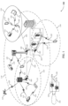
- FIG. 1 illustrates an example of a wireless communications system 100 that supports simultaneous feedback information and uplink shared channel transmissions in accordance with aspects of the present disclosure.
- the wireless communications system 100 may include one or more base stations 105, one or more UEs 115, and a core network 130.
- the wireless communications system 100 may be a Long Term Evolution (LTE) network, an LTE-Advanced (LTE-A) network, an LTE-A Pro network, or a New Radio (NR) network.
- LTE Long Term Evolution
- LTE-A LTE-Advanced
- LTE-A Pro LTE-A Pro
- NR New Radio
- the wireless communications system 100 may support enhanced broadband communications, ultra-reliable (e.g., mission critical) communications, low latency communications, communications with low-cost and low-complexity devices, or any combination thereof.
- ultra-reliable e.g., mission critical
- the base stations 105 may be dispersed throughout a geographic area to form the wireless communications system 100 and may be devices in different forms or having different capabilities.
- the base stations 105 and the UEs 115 may wirelessly communicate via one or more communication links 125.
- Each base station 105 may provide a coverage area 110 over which the UEs 115 and the base station 105 may establish one or more communication links 125.
- the coverage area 110 may be an example of a geographic area over which a base station 105 and a UE 115 may support the communication of signals according to one or more radio access technologies.
- the UEs 115 may be dispersed throughout a coverage area 110 of the wireless communications system 100, and each UE 115 may be stationary, or mobile, or both at different times.
- the UEs 115 may be devices in different forms or having different capabilities. Some example UEs 115 are illustrated in FIG. 1 .
- the UEs 115 described herein may be able to communicate with various types of devices, such as other UEs 115, the base stations 105, or network equipment (e.g., core network nodes, relay devices, integrated access and backhaul (IAB) nodes, or other network equipment), as shown in FIG. 1 .
- network equipment e.g., core network nodes, relay devices, integrated access and backhaul (IAB) nodes, or other network equipment
- the base stations 105 may communicate with the core network 130, or with one another, or both.
- the base stations 105 may interface with the core network 130 through one or more backhaul links 120 (e.g., via an S1, N2, N3, or other interface).
- the base stations 105 may communicate with one another over the backhaul links 120 (e.g., via an X2, Xn, or other interface) either directly (e.g., directly between base stations 105), or indirectly (e.g., via core network 130), or both.
- the backhaul links 120 may be or include one or more wireless links.
- One or more of the base stations 105 described herein may include or may be referred to by a person having ordinary skill in the art as a base transceiver station, a radio base station, an access point, a radio transceiver, a NodeB, an eNodeB (eNB), a next-generation NodeB or a giga-NodeB (either of which may be referred to as a gNB), a Home NodeB, a Home eNodeB, or other suitable terminology.
- a base transceiver station a radio base station
- an access point a radio transceiver
- a NodeB an eNodeB (eNB)
- eNB eNodeB
- next-generation NodeB or a giga-NodeB either of which may be referred to as a gNB
- gNB giga-NodeB
- a UE 115 may include or may be referred to as a mobile device, a wireless device, a remote device, a handheld device, or a subscriber device, or some other suitable terminology, where the "device” may also be referred to as a unit, a station, a terminal, or a client, among other examples.
- a UE 115 may also include or may be referred to as a personal electronic device such as a cellular phone, a personal digital assistant (PDA), a tablet computer, a laptop computer, or a personal computer.
- PDA personal digital assistant
- a UE 115 may include or be referred to as a wireless local loop (WLL) station, an Internet of Things (IoT) device, an Internet of Everything (IoE) device, or a machine type communications (MTC) device, among other examples, which may be implemented in various objects such as appliances, or vehicles, meters, among other examples.
- WLL wireless local loop
- IoT Internet of Things
- IoE Internet of Everything
- MTC machine type communications
- the UEs 115 described herein may be able to communicate with various types of devices, such as other UEs 115 that may sometimes act as relays as well as the base stations 105 and the network equipment including macro eNBs or gNBs, small cell eNBs or gNBs, or relay base stations, among other examples, as shown in FIG. 1 .
- devices such as other UEs 115 that may sometimes act as relays as well as the base stations 105 and the network equipment including macro eNBs or gNBs, small cell eNBs or gNBs, or relay base stations, among other examples, as shown in FIG. 1 .
- the UEs 115 and the base stations 105 may wirelessly communicate with one another via one or more communication links 125 over one or more carriers.
- carrier may refer to a set of radio frequency spectrum resources having a defined physical layer structure for supporting the communication links 125.
- a carrier used for a communication link 125 may include a portion of a radio frequency spectrum band (e.g., a bandwidth part (BWP)) that is operated according to one or more physical layer channels for a given radio access technology (e.g., LTE, LTE-A, LTE-A Pro, NR).
- Each physical layer channel may carry acquisition signaling (e.g., synchronization signals, system information), control signaling that coordinates operation for the carrier, user data, or other signaling.
- the wireless communications system 100 may support communication with a UE 115 using CA or multi-carrier operation.
- a UE 115 may be configured with multiple downlink component carriers and one or more uplink component carriers according to a CA configuration.
- CA may be used with both frequency division duplexing (FDD) and time division duplexing (TDD) component carriers.
- FDD frequency division duplexing
- TDD time division duplexing
- a carrier may be associated with a particular bandwidth of the radio frequency spectrum, and in some examples the carrier bandwidth may be referred to as a "system bandwidth" of the carrier or the wireless communications system 100.
- the carrier bandwidth may be one of a number of determined bandwidths for carriers of a particular radio access technology (e.g., 1.4, 3, 5, 10, 15, 20, 40, or 80 megahertz (MHz)).
- Devices of the wireless communications system 100 e.g., the base stations 105, the UEs 115, or both
- the wireless communications system 100 may include base stations 105 or UEs 115 that support simultaneous communications via carriers associated with multiple carrier bandwidths.
- each served UE 115 may be configured for operating over portions (e.g., a sub-band, a BWP) or all of a carrier bandwidth.
- Signal waveforms transmitted over a carrier may be made up of multiple subcarriers (e.g., using multi-carrier modulation (MCM) techniques such as orthogonal frequency division multiplexing (OFDM) or discrete Fourier transform spread OFDM (DFT-S-OFDM)).
- MCM multi-carrier modulation
- OFDM orthogonal frequency division multiplexing
- DFT-S-OFDM discrete Fourier transform spread OFDM
- a resource element may consist of one symbol period (e.g., a duration of one modulation symbol) and one subcarrier, where the symbol period and SCS are inversely related.
- the number of bits carried by each resource element may depend on the modulation scheme (e.g., the order of the modulation scheme, the coding rate of the modulation scheme, or both).
- One or more numerologies for a carrier may be supported, where a numerology may include a SCS ( ⁇ f ) and a cyclic prefix.
- a carrier may be divided into one or more BWPs having the same or different numerologies.
- a UE 115 may be configured with multiple BWPs.
- a single BWP for a carrier may be active at a given time and communications for the UE 115 may be restricted to one or more active BWPs.
- Time intervals of a communications resource may be organized according to radio frames each having a specified duration (e.g., 10 milliseconds (ms)). Each radio frame may be identified by a system frame number (SFN) (e.g., ranging from 0 to 1023).
- SFN system frame number
- Each frame may include multiple consecutively numbered subframes or slots, and each subframe or slot may have the same duration.
- a frame may be divided (e.g., in the time domain) into subframes, and each subframe may be further divided into a number of slots.
- each frame may include a variable number of slots, and the number of slots may depend on SCS.
- Each slot may include a number of symbol periods (e.g., depending on the length of the cyclic prefix prepended to each symbol period).
- a slot may further be divided into multiple mini-slots containing one or more symbols. Excluding the cyclic prefix, each symbol period may contain one or more (e.g., N f ) sampling periods. The duration of a symbol period may depend on the SCS or frequency band of operation.
- a subframe, a slot, a mini-slot, or a symbol may be the smallest scheduling unit (e.g., in the time domain) of the wireless communications system 100 and may be referred to as a transmission time interval (TTI).
- TTI duration e.g., the number of symbol periods in a TTI
- the smallest scheduling unit of the wireless communications system 100 may be dynamically selected (e.g., in bursts of shortened TTIs (sTTIs)).
- Physical channels may be multiplexed on a carrier according to various techniques.
- a physical control channel and a physical data channel may be multiplexed on a downlink carrier, for example, using one or more of time division multiplexing (TDM) techniques, frequency division multiplexing (FDM) techniques, or hybrid TDM-FDM techniques.
- a control region e.g., a control resource set (CORESET)
- CORESET control resource set
- One or more control regions (e.g., CORESETs) may be configured for a set of the UEs 115.
- one or more of the UEs 115 may monitor or search control regions for control information according to one or more search space sets, and each search space set may include one or multiple control channel candidates in one or more aggregation levels arranged in a cascaded manner.
- An aggregation level for a control channel candidate may refer to a number of control channel resources (e.g., control channel elements (CCEs)) associated with encoded information for a control information format having a given payload size.
- Search space sets may include common search space sets configured for sending control information to multiple UEs 115 and UE-specific search space sets for sending control information to a specific UE 115.
- a base station 105 may be movable and therefore provide communication coverage for a moving geographic coverage area 110.
- different geographic coverage areas 110 associated with different technologies may overlap, but the different geographic coverage areas 110 may be supported by the same base station 105.
- the overlapping geographic coverage areas 110 associated with different technologies may be supported by different base stations 105.
- the wireless communications system 100 may include, for example, a heterogeneous network in which different types of the base stations 105 provide coverage for various geographic coverage areas 110 using the same or different radio access technologies.
- the wireless communications system 100 may be configured to support ultra-reliable communications or low-latency communications, or various combinations thereof.
- the wireless communications system 100 may be configured to support ultra-reliable low-latency communications (URLLC) or mission critical communications.
- the UEs 115 may be designed to support ultra-reliable, low-latency, or critical functions (e.g., mission critical functions).
- Ultra-reliable communications may include private communication or group communication and may be supported by one or more mission critical services such as mission critical push-to-talk (MCPTT), mission critical video (MCVideo), or mission critical data (MCData).
- MCPTT mission critical push-to-talk
- MCVideo mission critical video
- MCData mission critical data
- Support for mission critical functions may include prioritization of services, and mission critical services may be used for public safety or general commercial applications.
- the terms ultra-reliable, low-latency, mission critical, and ultra-reliable low-latency may be used interchangeably herein.
- a UE 115 may also be able to communicate directly with other UEs 115 over a device-to-device (D2D) communication link 135 (e.g., using a peer-to-peer (P2P) or D2D protocol).
- D2D device-to-device
- P2P peer-to-peer
- One or more UEs 115 utilizing D2D communications may be within the geographic coverage area 110 of a base station 105.
- Other UEs 115 in such a group may be outside the geographic coverage area 110 of a base station 105 or be otherwise unable to receive transmissions from a base station 105.
- groups of the UEs 115 communicating via D2D communications may utilize a one-to-many (1:M) system in which each UE 115 transmits to every other UE 115 in the group.
- a base station 105 facilitates the scheduling of resources for D2D communications. In other cases, D2D communications are carried out between the UEs 115 without the involvement of a base station 105.
- the core network 130 may provide user authentication, access authorization, tracking, Internet Protocol (IP) connectivity, and other access, routing, or mobility functions.
- the core network 130 may be an evolved packet core (EPC) or 5G core (5GC), which may include at least one control plane entity that manages access and mobility (e.g., a mobility management entity (MME), an access and mobility management function (AMF)) and at least one user plane entity that routes packets or interconnects to external networks (e.g., a serving gateway (S-GW), a Packet Data Network (PDN) gateway (P-GW), or a user plane function (UPF)).
- EPC evolved packet core
- 5GC 5G core
- MME mobility management entity
- AMF access and mobility management function
- S-GW serving gateway
- PDN Packet Data Network gateway
- UPF user plane function
- the control plane entity may manage non-access stratum (NAS) functions such as mobility, authentication, and bearer management for the UEs 115 served by the base stations 105 associated with the core network 130.
- NAS non-access stratum
- User IP packets may be transferred through the user plane entity, which may provide IP address allocation as well as other functions.
- the user plane entity may be connected to the network operators IP services 150.
- the network operators IP services 150 may include access to the Internet, Intranet(s), an IP Multimedia Subsystem (IMS), or a Packet-Switched Streaming Service.
- Some of the network devices may include subcomponents such as an access network entity 140, which may be an example of an access node controller (ANC).
- Each access network entity 140 may communicate with the UEs 115 through one or more other access network transmission entities 145, which may be referred to as radio heads, smart radio heads, or transmission/reception points (TRPs).
- Each access network transmission entity 145 may include one or more antenna panels.
- various functions of each access network entity 140 or base station 105 may be distributed across various network devices (e.g., radio heads and ANCs) or consolidated into a single network device (e.g., a base station 105).
- the wireless communications system 100 may operate using one or more frequency bands, typically in the range of 300 megahertz (MHz) to 300 gigahertz (GHz).
- the region from 300 MHz to 3 GHz is known as the ultra-high frequency (UHF) region or decimeter band because the wavelengths range from approximately one decimeter to one meter in length.
- UHF waves may be blocked or redirected by buildings and environmental features, but the waves may penetrate structures sufficiently for a macro cell to provide service to the UEs 115 located indoors.
- the transmission of UHF waves may be associated with smaller antennas and shorter ranges (e.g., less than 100 kilometers) compared to transmission using the smaller frequencies and longer waves of the high frequency (HF) or very high frequency (VHF) portion of the spectrum below 300 MHz.
- HF high frequency
- VHF very high frequency
- the wireless communications system 100 may utilize both licensed and unlicensed radio frequency spectrum bands.
- the wireless communications system 100 may employ LAA, LTE-Unlicensed (LTE-U) radio access technology, or NR technology in an unlicensed band such as the 5 GHz industrial, scientific, and medical (ISM) band.
- LTE-U LTE-Unlicensed
- NR NR technology
- an unlicensed band such as the 5 GHz industrial, scientific, and medical (ISM) band.
- devices such as the base stations 105 and the UEs 115 may employ carrier sensing for collision detection and avoidance.
- operations in unlicensed bands may be based on a CA configuration in conjunction with component carriers operating in a licensed band (e.g., LAA).
- Operations in unlicensed spectrum may include downlink transmissions, uplink transmissions, P2P transmissions, or D2D transmissions, among other examples.
- a base station 105 or a UE 115 may be equipped with multiple antennas, which may be used to employ techniques such as transmit diversity, receive diversity, multiple-input multiple-output (MIMO) communications, or beamforming.
- the antennas of a base station 105 or a UE 115 may be located within one or more antenna arrays or antenna panels, which may support MIMO operations or transmit or receive beamforming.
- one or more base station antennas or antenna arrays may be co-located at an antenna assembly, such as an antenna tower.
- antennas or antenna arrays associated with a base station 105 may be located in diverse geographic locations.
- a base station 105 may have an antenna array with a number of rows and columns of antenna ports that the base station 105 may use to support beamforming of communications with a UE 115.
- a UE 115 may have one or more antenna arrays that may support various MIMO or beamforming operations.
- an antenna panel may support radio frequency beamforming for a signal transmitted via an antenna port.
- Beamforming which may also be referred to as spatial filtering, directional transmission, or directional reception, is a signal processing technique that may be used at a transmitting device or a receiving device (e.g., a base station 105, a UE 115) to shape or steer an antenna beam (e.g., a transmit beam, a receive beam) along a spatial path between the transmitting device and the receiving device.
- Beamforming may be achieved by combining the signals communicated via antenna elements of an antenna array such that some signals propagating at particular orientations with respect to an antenna array experience constructive interference while others experience destructive interference.
- the adjustment of signals communicated via the antenna elements may include a transmitting device or a receiving device applying amplitude offsets, phase offsets, or both to signals carried via the antenna elements associated with the device.
- the adjustments associated with each of the antenna elements may be defined by a beamforming weight set associated with a particular orientation (e.g., with respect to the antenna array of the transmitting device or receiving device, or with respect to some other orientation).
- the UEs 115 and the base stations 105 may support retransmissions of data to increase the likelihood that data is received successfully.
- HARQ feedback is one technique for increasing the likelihood that data is received correctly over a communication link 125.
- HARQ may include a combination of error detection (e.g., using a cyclic redundancy check (CRC)), forward error correction (FEC), and retransmission (e.g., automatic repeat request (ARQ)).
- FEC forward error correction
- ARQ automatic repeat request
- HARQ may improve throughput at the medium access control (MAC) layer in poor radio conditions (e.g., low signal-to-noise conditions).
- MAC medium access control
- a device may support same-slot HARQ feedback, where the device may provide HARQ feedback in a specific slot for data received in a previous symbol in the slot. In other cases, the device may provide HARQ feedback in a subsequent slot, or according to some other time interval.
- wireless communications system 100 may support simultaneous PUCCH-PUSCH transmission by UEs 115.
- wireless communications system 100 may support and enable simultaneous PUCCH-PUSCH across two or more carriers.
- a carrier configured for a PUSCH transmission may further be configured to disable control information (e.g., a carrier configured for PUSCH in a simultaneous PUCCH-PUSCH scenario may be configured as a data only carrier or non-piggyback carrier).
- wireless communications system 100 may configure (e.g., via RRC signaling) simultaneous PUCCH-PUSCH across two or more carriers, where piggybacking of feedback information on uplink shared channel transmission may be disabled.
- wireless communications system 100 may configure simultaneous PUCCH-PUSCH such that feedback information (e.g., HARQ feedback, P-CSI) of PUCCH may not be piggybacked (e.g., multiplexed) on the PUSCH (e.g., as the PUCCH and PUSCH may be transmitted simultaneously).
- feedback information e.g., HARQ feedback, P-CSI
- P-CSI feedback information
- Configuring UEs 115 with simultaneous PUCCH-PUSCH and disabling UCI piggybacking on PUSCH for some uplink carriers may allow utilization of some SCells for data only, which may provide for more efficient handling of control information (e.g., improved HARQ procedures), improved data throughput (e.g., on PUSCH), etc.
- FIG. 2 illustrates an example of a wireless communications system 200 that supports simultaneous feedback information and uplink shared channel transmissions in accordance with aspects of the present disclosure.
- wireless communications system 200 may implement aspects of wireless communication system 100.
- UE 115-a may be an example of a UE 115 as described with respect to FIG. 1
- base station 105-a may be an example of a base station 105 as described with respect to FIG. 1 .
- Base station 105-a may serve a coverage area 110-a, which may include UE 115-a.
- base station 105-a and UE 115-a may communicate using various CA schemes.
- UE 115-a may communicate with base station 105-a using an uplink CA configuration (e.g., which may include, for example, two uplink carriers in the example illustrated by FIG. 2 ).
- wireless communications system 200 may support simultaneous transmission of PUCCH transmission 205 and PUSCH transmission 210 (e.g., which may be referred to as simultaneous PUCCH-PUSCH).
- Base station 105-a may transmit an uplink grant 215 to UE 115-a.
- Uplink grant 215 may schedule a set of uplink resources for UE 115-a to use to transmit an uplink transmission (e.g., a PUSCH transmission 210).
- a UE 115-a may transmit a scheduling request (SR) to base station 105-a, prompting base station 105-a to transmit the uplink grant 215 to UE 115-a.
- SR scheduling request
- UE 115-a may identify pending (e.g., buffered) data to be transmitted to base station 105-a, and UE 115-a may, accordingly, transmit an SR to base station 105-a to request uplink resources for transmission of the pending data.
- base station 105-a may transmit uplink grant 215 to UE 115-a, and UE 115-a may transmit uplink data (e.g., PUSCH transmission 210) to the base station 105-a using time and frequency resources indicated by the uplink grant 215.
- uplink data e.g., PUSCH transmission 210
- base station 105-a may transmit a downlink grant (e.g., downlink assignment, scheduling assignment) to UE 115-a.
- the downlink grant may include resources indicating a downlink transmission, such as a PDSCH message, from base station 105-a.
- UE 115-a may then monitor the indicated resources for the PDSCH message, and attempt to decode the message. Based on monitoring the resources and attempted decoding, UE 115-a may generate feedback information for the PDSCH.
- the feedback information may be transmitted by UE 115-a in an uplink message.
- UE 115-a may transmit HARQ feedback, such as an acknowledgment (ACK), or a negative acknowledgment (NACK).
- ACK acknowledgment
- NACK negative acknowledgment
- An ACK may be transmitted based on a successful reception and decoding of a message from base station 105-a, and a NACK may be transmitted based on unsuccessful reception or decoding of the PDSCH transmission.
- the feedback information may be transmitted in a PUCCH scheduled by an uplink grant transmitted to UE 115-a by base station 105-a (e.g., which may be included in PDSCH, may be included in the original downlink grant, may be a separate uplink grant, etc.).
- UE 115-a may piggyback feedback information (e.g., an ACK/NACK for a downlink shared channel transmission) in PUSCH transmission 210.
- a PUCCH transmission 205 may be scheduled for a time overlapped with a PUSCH transmission 210. Therefore, UE 115-a may use the PUSCH transmission 210 to transmit feedback information.
- UE 115-a may piggyback UCI on the PUSCH transmission 210 (e.g., HARQ feedback, P-CSI, etc. may be multiplexed onto PUSCH and may be transmitted via PUSCH transmission 210) and UE 115-a may refrain from transmitting the PUCCH.
- a CA configuration may include one or more carriers in the unlicensed band (e.g., in examples where wireless communications system 200 illustrates an LAA system).
- UE 115-a may perform listen-before-talk (LBT) procedures prior to accessing the medium.
- LBT listen-before-talk
- reliance on UCI piggybacking for communicating feedback information may be inefficient, as the UE 115-a may or may not ultimately win access to the medium for PUSCH transmission 210 on a carrier in the unlicensed band.
- the described techniques may be implemented to disable UCI piggybacking on such carriers in the unlicensed band (e.g., which may provide for improved reliability of UCI via PUCCH transmissions 205, may provide for improved throughput data only carriers via PUSCH transmissions 210, etc.).
- simultaneous PUCCH-PUSCH may be configured via RRC signaling.
- RRC configuration may enable simultaneous PUCCH-PUSCH across carriers and, once configured for a particular PUSCH, multiplexing of UCI from PUCCH may be disabled for the particular PUSCH configured for simultaneous PUCCH-PUSCH.
- RRC signaling for simultaneous PUCCH-PUSCH configuration may include configuration of data only carriers (e.g., where UCI piggybacking is disabled) on a per carrier basis, on a per group of uplink carriers basis, on a per cell-group/PUCCH-group basis, etc.
- the T-DAI field may not be included in a DCI scheduling a data-only uplink carrier.
- UE 115-a may receive uplink DCI scheduling a PUSCH that does not have piggybacking disabled.
- the DCI scheduling the piggybacking supporting carrier may include a T-DAI field.
- the T-DAI field on the uplink DCI scheduling the piggybacking carrier may indicate the HARQ feedback codebook size for transmitting HARQ feedback (e.g., UCI) in a PUSCH on the piggybacking carrier.
- UE 115-a may transmit the HARQ feedback using a PUCCH, where the HARQ feedback codebook size may be determined based on the T-DAI field value in the uplink or downlink DCI.
- the T-DAI field included in the DCI scheduling a data-only PUSCH may be interpreted by UE 115-a as a HARQ feedback codebook size indicator that UE 115-a may use to configure the HARQ feedback in the PUCCH.
- FIG. 3 illustrates an example of a CA scheme 300 that supports simultaneous feedback information and uplink shared channel transmissions in accordance with aspects of the present disclosure.
- CA scheme 300 may implement aspects of wireless communication system 100.
- CA scheme 300 may be implemented by UEs that may be examples of UEs as described with respect to FIGs. 1 and 2 , and base stations that may examples of base stations as described with respect to FIGs. 1 and 2 .
- a base station and UE may communicate using various CA schemes.
- a UE may communicate with a base station using an uplink CA configuration (e.g., which may include, for example, three uplink carriers in the example illustrated by FIG. 3 ).
- CA scheme 300 may support simultaneous transmission of PUCCH transmission and PUSCH transmission (e.g., which may be referred to as simultaneous PUCCH-PUSCH).
- a UE may determine feedback information 310 such as HARQ ACK/NACK, or channel state information (CSI), or a combination thereof for one or more of the uplink carriers 330.
- the UE may receive an uplink grant 315 that configures a future uplink shared channel 320 transmission that is scheduled at the same time an uplink control channel transmission 325 is scheduled.
- a UE may not be configured to simultaneously transmit feedback information 310 on an uplink control channel 325 (e.g., PUCCH) and an uplink shared channel 320 (e.g., PUSCH).
- the UE may instead multiplex (e.g., piggyback) the feedback information 310 with the uplink shared channel 320 and drop the uplink control channel 325.
- network reliability and efficiency may be increased by enabling a feedback information 310 (e.g., UCI, HARQ ACK/NACK) disabling scheme.
- a UE may receive a feedback information 310 piggybacking status for one or more uplink carriers via RRC signaling, which may disable piggybacking on the one or more uplink carriers, or enable piggybacking on the one or more uplink carriers, or a combination thereof to enable simultaneous PUCCH-PUSCH transmissions by the UE.
- the RRC signaling may indicate disabled piggybacking on a per-uplink carrier 330 basis, a per-group of uplink carriers 330 basis, a per-cell-group basis, or a per-PUCCH group basis, or a combination thereof.
- the RRC signaling may individually indicate one or more uplink carriers 330 that are disabled for piggybacking.
- the RRC signaling may indicate a group of uplink carriers 330 that are disabled for piggyback based on frequency band, frequency range, TA group, per cell-group, per PUCCH group, or per UE.
- the RRC signaling may indicate per group of cells or group of PUCCHs an SCell or multiple SCells in the bands other than the band associated with the PCell that are data only carriers.
- the UE may receive a piggybacking status (e.g., feedback information piggybacking status, uplink control information piggybacking status) via an RRC parameter that indicates one or more uplink carriers 330 are configured as a data-only channel.
- the RRC signaling may indicate UCI piggybacking is disabled for uplink carrier 330-a, uplink carrier 330-b, or a combination thereof, where uplink carriers 330-a and 330-b may be in different frequency bands.
- the feedback information 310 may be carried by uplink control channel 325, where the uplink control channel 325 may be scheduled at the same time an uplink shared channel 320 is scheduled by an uplink grant 315.
- feedback information 310 regarding one or more symbols 305 on one or more carriers such as feedback information 310 relating to uplink carriers 330-a, 330-b, and 330-c may be transmitted by uplink control channel 325.
- the uplink control channel 325, carrying the feedback information 310 may be transmitted at the same time an uplink shared channel 320 is transmitted.
- the UE may be configured to simultaneously transmit an uplink control channel 325 and an uplink shared channel 320 on different frequency bands (e.g., sub-6, mmW).
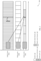
- FIG. 4 illustrates an example of a CA scheme 400 that supports simultaneous feedback information and uplink shared channel transmissions in accordance with aspects of the present disclosure.
- CA scheme 400 may implement aspects of wireless communication system 100.
- CA scheme 400 may be implemented by UEs that may be examples of UEs as described with respect to FIGs. 1 and 2 , and base stations that may examples of base stations as described with respect to FIGs. 1 and 2 .
- a UE may be configured for CA using a first uplink carrier 430-c that is a PCell, a second uplink carrier 430-b that is a first SCell, and a third uplink carrier 430-a that is a second SCell, as described above with respect to FIG. 2 .
- a UE may be configured to simultaneously transmit feedback information 410 and uplink shared channels 420 across different frequency bands and a UE may be configured to multiplex UCI with an uplink shared channel 420 on one of the frequency bands. For example, the UE may receive a piggybacking status via an RRC parameter that indicates uplink carrier 430-a in a second frequency band (e.g., sub-6, mmW) is configured as a data-only channel where UCI piggybacking is disabled for uplink carrier 430-a.
- a second frequency band e.g., sub-6, mmW
- feedback information 410 associated with uplink carriers 430-a, 430-b, and 430-c may not be transmitted on uplink carrier 430-a during uplink shared channel 420.
- HARQ ACK/NACK and CSI e.g., P-CSI
- a UE may be configured to piggyback a portion or all of the feedback information 410 from each of the uplink carriers 430 in uplink shared channel 420 of uplink carrier 430-b, where piggybacking may refer to multiplexing UCI onto an uplink shared channel 420 transmission.
- the feedback information 410 that would be carried in an uplink control channel 425 of uplink carrier 430-c may be piggybacked with uplink shared channel 420 of uplink carrier 430-b.
- the UE may transmit the two uplink shared channels 420 on uplink carriers 430-a, and 430-b and the uplink control channel 425 on uplink carrier 430-c simultaneously.
- the feedback information 410 may be piggybacked on uplink shared channel 420 on uplink carrier 430-b, the uplink control channel 425 on uplink carrier 430-c may be dropped. In some cases, the feedback information 410 may be piggybacked based on uplink carriers 430-b and 430-c being in the same frequency band.
- feedback information 410 regarding one or more symbols 405 on one or more uplink carriers 430 may be transmitted by uplink shared channel 420 on uplink carrier 430-b.
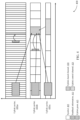
- FIG. 5 illustrates an example of a CA scheme 500 that supports simultaneous feedback information and uplink shared channel transmissions in accordance with aspects of the present disclosure.
- CA scheme 500 may implement aspects of wireless communication system 100.
- CA scheme 500 may be implemented by UEs that may be examples of UEs as described with respect to FIGs. 1 and 2 , and base stations that may examples of base stations as described with respect to FIGs. 1 and 2 .
- a UE may be configured for CA using a first uplink carrier 530-c that is a PCell, a second uplink carrier 530-b that is a first SCell, and a third uplink carrier 530-a that is a second SCell, as described above with respect to FIG. 2 .
- a UE may be configured to simultaneously transmit feedback information 510 and uplink shared channels 520 across different frequency bands. For example, the UE may receive a piggybacking status via an RRC parameter that indicates uplink carrier 530-a in a second frequency band and uplink carrier 530-b in a first frequency band are configured as a data-only channels where UCI piggybacking is disabled for uplink carriers 530-a and 530-b.
- the feedback information 510 may be carried by uplink control channel 525 on uplink carrier 530-c of a first frequency band, where the uplink control channel 525 may be scheduled at the same time an uplink shared channel 520 is scheduled by an uplink grant 515.
- feedback information 510 regarding one or more symbols 505 on one or more uplink carriers 530 such as feedback information 510 relating to uplink carriers 530-a, 530-b, and 530-c may be transmitted by uplink control channel 525 on uplink carrier 530-c.
- the uplink control channel 525 carrying the feedback information 510, may be transmitted at the same time one or more uplink shared channels 520 are transmitted.
- the UE may be configured to simultaneously transmit an uplink control channel 525 and an uplink shared channel 520.
- the UE may transmit the two uplink shared channels 520 on uplink carriers 530-a, and 530-b and the uplink control channel 525 on uplink carrier 530-c simultaneously.
- the feedback information 510 may be piggybacked based on uplink carriers 530-b and 530-c being in the same frequency band.
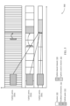
- FIG. 6 illustrates an example of a CA scheme 600 that supports simultaneous feedback information and uplink shared channel transmissions in accordance with aspects of the present disclosure.
- CA scheme 600 may implement aspects of wireless communication system 100.
- CA scheme 600 may be implemented by UEs that may be examples of UEs as described with respect to FIGs. 1 and 2 , and base stations that may examples of base stations as described with respect to FIGs. 1 and 2 .
- a UE may be configured for CA using a first uplink carrier 630-b that is a PCell, and a second uplink carrier 630-a that is a first SCell, as described above with respect to FIG. 2 .
- a UE may be configured to simultaneously transmit feedback information 610 and an uplink shared channel 620 across the same frequency band.
- the UE may receive a piggybacking status via an RRC parameter that indicates uplink carrier 630-a is configured as a data-only channel where UCI piggybacking is disabled for uplink carriers 630-a.
- feedback information 610 associated with uplink carriers 630-a, and 630-b such as HARQ ACK/NACK and CSI (e.g., P-CSI), may not be transmitted on uplink carrier 630-a during uplink shared channel 620.
- the feedback information 610 may be carried by uplink control channel 625 on uplink carrier 630-b, where the uplink control channel 625 may be scheduled at the same time an uplink shared channel 620 is scheduled by an uplink grant 615.
- feedback information 610 regarding one or more symbols 605 on one or more uplink carriers 630 such as feedback information 610 relating to uplink carriers 630-a, and 630-b may be transmitted by uplink control channel 625 on uplink carrier 630-b.
- the uplink control channel 625, carrying the feedback information 610 may be transmitted at the same time one or more uplink shared channels 620 are transmitted.
- the UE may be configured to simultaneously transmit an uplink control channel 625 and an uplink shared channel 620 in the same frequency band.
- aperiodic CSI A-CSI
- SP-CSI semi-persistent CSI
- uplink DCI A-CSI/SP-CSI
- the uplink shared channel 620 may collide with feedback information 610 transmitted simultaneously in the uplink control channel 625.
- the uplink shared channel 620 may be configured as a data only channel and may not support piggybacking A-CSI/SP-CSI.
- a UE may be configured such that A-CSI/SP-CSI is not activated for an uplink shared channel 620 on a data-only uplink carrier 630 such that A-CSI/SP-CSI may be disabled for a data only uplink carrier 630.
- a CSI request field in a DCI may be associated with activated A-CSI.
- a UE or base station may configure the CSI request field in DCI to not activate the A-CSI for an uplink shared channel 620 on the data-only uplink carrier 630.
- activation DCI may be associated with triggering SP-CSI and the base station or UE may configure the activation DCI with CRC scrambled by SP-CSI-RNTI such that the activation DCI may not activate SP-CSI.
- an uplink grant 615 may include an UL-SCH field that may indicate whether uplink data will be carried on a PUSCH.
- the UL-SCH field may be used to indicate that no data will be transmitted on the PUSCH and instead, A-CSI/SP-CSI may be transmitted on the PUSCH.
- the UL-SCH field may be set to preconfigured value (e.g., 1) if A-CSI/SP-CSI should not be triggered.
- a dynamic beta-offset field may indicate the code rate of the UCI on the PUSCH, if the uplink shared channel 620 is not configured as a data-only channel. As such the dynamic beta-offset file may control the code rate of the UCI and PUSCH.
- the dynamic beta-offset may be set to a fixed value (e.g., 0) so as not to indicate a code rate. Additionally or alternatively, the UE may be configured to ignore the dynamic beta-offset if the uplink carrier 630 associated with the dynamic beta-offset is configured as a data-only carrier. In some cases, the A-CSI/SP-CSI may be triggered for a PUSCH on uplink carrier 630 as the data-only carrier.
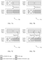
- FIGs. 7A, 7B, 7C, and 7D illustrate examples of CA schemes 700, 701, 702, and 703 that support simultaneous feedback information and uplink shared channel transmissions in accordance with aspects of the present disclosure.
- CA schemes 700, 701, 702, and 703 may implement aspects of wireless communication system 100.
- CA schemes 700, 701, 702, and 703 may be implemented by UEs that may be examples of UEs as described with respect to FIGs. 1 and 2 , and base stations that may examples of base stations as described with respect to FIGs. 1 and 2 .
- a base station and UE may communicate using various CA schemes.
- a UE may communicate with a base station using an uplink CA configuration (e.g., which may include, for example, at least two uplink carriers in the examples illustrated by FIGs. 7A, 7B, 7C, and 7D ).
- CA schemes 700, 701, 702, and 703 may support simultaneous transmission of PUCCH transmission and PUSCH transmission (e.g., which may be referred to as simultaneous PUCCH-PUSCH).
- an A-CSI/SP-CSI 715 may need to be appropriately configured relative to data-only carriers.
- A-CSI/SP-CSI 715 may be triggered for a PUSCH on the uplink data carrier 705.
- a base station may schedule uplink transmissions at a UE such that A-CSI/SP-CSI 715 on the PUSCH of the uplink data-only carrier and feedback information 730 (e.g., HARQ ACK/NACK, P-CSI, UCI) on the PUCCH or PUSCH of a non-data-only carrier do not overlap.
- the PUSCH carrying the A-CSI/SP-CSI 715 may be scheduled such that the PUSCH does not overlap with the PUCCH/PUSCH carrying the feedback information 730.
- uplink carrier 705 may include a PUSCH on an SCell, and uplink carrier 710 may include a PUCCH on a PCell.
- the uplink carriers 705 and 710 may operate in the same frequencies bands, or different frequency bands.
- Uplink carrier 705 may include an A-CSI/SP-CSI and an uplink shared channel 720 (e.g., UL-SCH).
- Uplink carrier 710 may include a P-CSI 725 and feedback information 730 (e.g., HARQ ACK/NACK, UCI).
- the UE may drop A-CSI/SP-CSI 715 in uplink carrier 705 and the UE may transmit uplink carriers 705-a and 710-a. Additionally or alternatively, as depicted in FIG. 7B , the UE may drop the P-CSI 725 in uplink carrier 710-b and simultaneously transmit uplink carriers 705-b and 710-b. Additionally or alternatively, as depicted in FIG. 7C , the UE may drop the P-CSI 725 in uplink carrier 710-c and piggyback the feedback information 730 with the uplink shared channel 720 on uplink carrier 705-c.
- the UE may transmit uplink carrier 705-c and drop uplink carrier 710-c.
- the UE may be configured with more than two uplink carriers as described with reference to FIGs. 3 through 5 .
- the UE may be configured with another uplink carrier such that UE may simultaneously transmit the piggybacked feedback information and one or more other PUSCH transmissions, PUCCH transmissions, or a combination thereof. Additionally or alternatively, as depicted in FIG.
- the UE may partially drop the P-CSI 725 in uplink carrier 710-d and may piggyback the remaining P-CSI 725 with the A-CSI/SP-CSI 715 on uplink carries 705-d.
- the UE may also piggyback the feedback information 730 with the uplink shared channel 720 on uplink carrier 705-d.
- the UE may transmit uplink carrier 705-d and drop uplink carrier 710-d.
- the UE may be configured with more than two uplink carriers as described with reference to FIGs. 3 through 5 .
- the UE may drop an uplink carrier and piggyback feedback information on a PUSCH
- the UE may be configured with another uplink carrier such that UE may simultaneously transmit the piggybacked feedback information and one or more other PUSCH transmissions, PUCCH transmissions, or a combination thereof.
- T proc,2 is the minimum PUSCH preparation time for a PUSCH scheduled on an uplink data carrier, if the PUSCH does not carry feedback information.
- the minimum PUSCH preparation time may be irrespective of whether or how feedback information is piggybacked on other uplink carriers.
- the minimum PUSCH preparation time for the PUSCH on an uplink carrier, that is not piggybacked with feedback information may not be impacted by the processing timeline for other uplink carriers.
- the minimum processing timelines for other carriers e.g., PDSCH processing preparation for PUSCH, CSI computation and preparation
- the minimum PUSCH preparation time may be based on the maximum T proc,2 for any overlapped PUSCHs and based on the minimum SCS configuration.
- the minimum SCS configuration may be a part of SCS configurations used for physical downlink control channel (PDCCH) scheduling the i-th PUSCH, i being an integer index, the PDCCHs scheduling the PDSCHs with corresponding HARQ ACK/NACK transmissions on a PUCCH which may be in the group of overlapping PUCCHs/PUSCHs described with reference to FIGs. 7A through 7B , and all PUSCHs in the group of overlapping PUCCHs and PUSCHs described with reference to FIGs. 7A through 7B .
- PUCCH physical downlink control channel
- FIG. 8 illustrates an example of a process flow 800 that supports simultaneous feedback information and uplink shared channel transmissions in accordance with aspects of the present disclosure.
- the process flow 800 may illustrate an example of a simultaneous feedback information transmission and shared channel transmission scheme.
- UE 115-b may be configured to transmit feedback information and an uplink shared channel simultaneously in different subcarriers to base station 105-b.
- Base station 105-b and UE 115-b may be examples of the corresponding wireless devices described with reference to FIGs. 1 through 7 .
- a different type of wireless device e.g., a base station 105
- Alternative examples of the following may be implemented, where some steps are performed in a different order than described or are not performed at all. In some cases, steps may include additional features not mentioned below, or further steps may be added.
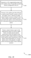
- UE 115-b may receive a piggybacking status for a first uplink carrier of a set of uplink carriers configured for UE 115-b.
- UE 115-b may receive a control message including an indication that uplink control information piggybacking (e.g., feedback information piggybacking) is disabled for the first uplink carrier.
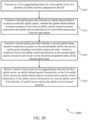
- UE 115-b may receive a control message including an indication that uplink control information piggybacking is disabled for a group of uplink carriers within the set of uplink carriers, where the group of uplink carriers includes the first uplink carrier.
- UE 115-b may receive a control message including an indication that uplink control information piggybacking is enabled for a group of uplink carriers within the set of uplink carriers, where the first uplink carrier is absent from the group of uplink carriers, and where the control message is configured per cell-group, or per uplink control channel group, or a combination thereof.
- UE 115-b may receive a first uplink grant that indicates an uplink shared channel occasion on the first uplink carrier.
- UE 115-b may receive a downlink assignment index in the first uplink grant, where performing the uplink shared channel transmission includes encoding the uplink shared channel transmission irrespective of the downlink assignment index.
- UE 115-b may generate uplink control information (e.g., feedback information) for a downlink transmission from base station 105-b, where the uplink control information may be associated with an uplink control channel occasion that overlaps in time with the uplink shared channel occasion.
- uplink control information e.g., feedback information
- UE 115-b may select the second uplink carrier for the uplink control transmission based on the piggybacking status for the first uplink carrier and the uplink control channel occasion overlapping in time with the uplink shared channel occasion.
- UE 115-b may perform, based on the piggybacking status for the first uplink carrier, an uplink shared channel transmission on the first uplink carrier during the uplink shared channel occasion and a uplink control transmission of the uplink control information on a second uplink carrier of the set of uplink carriers during the uplink control channel occasion. In some cases, UE 115-b may transmit the uplink shared channel transmission and the uplink control transmission to base station 105-b.
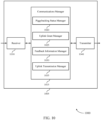
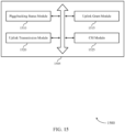
- FIG. 9 shows a block diagram 900 of a device 905 that supports simultaneous feedback information and uplink shared channel transmissions in accordance with aspects of the present disclosure.
- the device 905 may be an example of aspects of a UE 115 as described herein.
- the device 905 may include a receiver 910, a communications manager 915, and a transmitter 920.
- the device 905 may also include a processor. Each of these components may be in communication with one another (e.g., via one or more buses).
Landscapes
- Engineering & Computer Science (AREA)
- Signal Processing (AREA)
- Computer Networks & Wireless Communication (AREA)
- Quality & Reliability (AREA)
- Mobile Radio Communication Systems (AREA)
Claims (15)
- Verfahren (800) zur drahtlosen Kommunikation an einem Benutzergerät, UE (115-b), umfassend:Empfangen (805) eines Huckepack-Status für einen ersten Uplink-Träger einer Vielzahl von Uplink-Trägern, die für das UE konfiguriert sind;Empfangen (810) einer ersten Uplink-Gewährung, die eine gemeinsame Uplink-Kanalgelegenheit auf dem ersten Uplink-Träger anzeigt;Erzeugen (815) von Uplink-Steuerinformation für eine Downlink-Übertragung von einer Basisstation (105-b), wobei die Uplink-Steuerinformation mit einer Uplink-Steuerkanalgelegenheit assoziiert ist, die sich zeitlich mit der gemeinsamen Uplink-Kanalgelegenheit überlappt; undDurchführen (820), basierend zumindest teilweise auf dem Huckepack-Status für den ersten Uplink-Träger, einer gemeinsamen Uplink-Kanalübertragung auf dem ersten Uplink-Träger während der gemeinsamen Uplink-Kanalgelegenheit und einer Uplink-Steuerübertragung der Uplink-Steuerinformation auf einem zweiten Uplink-Träger der Vielzahl von Uplink-Trägern während der Uplink-Steuerkanalgelegenheit.
- Verfahren nach Anspruch 1, ferner umfassend:
Auswählen des zweiten Uplink-Trägers für die Uplink-Steuerübertragung basierend zumindest teilweise auf dem Huckepack-Status für den ersten Uplink-Träger und der Uplink-Steuerkanalgelegenheit, die sich zeitlich mit der gemeinsamen Uplink-Kanalgelegenheit überlappt. - Verfahren nach Anspruch 1, wobei das Empfangen des Huckepack-Status für den ersten Uplink-Träger umfasst:
Empfangen einer Steuernachricht, die eine Anzeige umfasst, dass das Huckepacken von Uplink-Steuerinformation für den ersten Uplink-Träger deaktiviert ist, oder Empfangen einer Steuernachricht, die eine Anzeige umfasst, dass das Huckepacken von Uplink-Steuerinformation für eine Gruppe von Uplink-Trägern innerhalb der Vielzahl von Uplink-Trägern deaktiviert ist, wobei die Gruppe von Uplink-Trägern den ersten Uplink-Träger umfasst, wobei die Gruppe von Uplink-Trägern gemäß einem oder mehreren von Folgendem gruppiert ist:
Frequenzbereich, Frequenzband, Timing-Advance-Gruppe, Zellengruppe, physikalischer Uplink-Steuerkanalgruppe oder UE, oder Empfangen einer Steuernachricht, die eine Anzeige umfasst, dass das Huckepacken von Uplink-Steuerinformation für eine Gruppe von Uplink-Trägern innerhalb der Vielzahl von Uplink-Trägern aktiviert ist, wobei der erste Uplink-Träger in der Gruppe von Uplink-Trägern fehlt, wobei die Steuernachricht pro Zellengruppe oder pro Uplink-Steuerkanalgruppe oder einer Kombination davon konfiguriert ist. - Verfahren nach Anspruch 1, wobei das Empfangen der ersten Uplink-Gewährung umfasst:Empfangen eines Downlink-Zuweisungsindex in der ersten Uplink-Gewährung; undwobei das Durchführen der gemeinsamen Uplink-Kanalübertragung das Codieren der gemeinsamen Uplink-Kanalübertragung unabhängig von dem Downlink-Zuweisungsindex umfasst, ferner umfassend:
Ignorieren des Downlink-Zuweisungsindex in der ersten Uplink-Gewährung basierend zumindest teilweise auf dem Huckepack-Status für den ersten Uplink-Träger, und/oder wobei der Downlink-Zuweisungsindex in der ersten Uplink-Gewährung auf einem vorkonfigurierten Wert basierend zumindest teilweise auf dem Huckepack-Status für den ersten Uplink-Träger festgelegt ist, und/oder ferner umfassend:
Bestimmen einer Codebuchgröße für die Uplink-Steuerübertragung auf dem zweiten Uplink-Träger basierend zumindest teilweise auf dem Downlink-Zuweisungsindex in der ersten Uplink-Gewährung. - Verfahren nach Anspruch 1, ferner umfassend:Empfangen einer zweiten Uplink-Gewährung, die eine zweite gemeinsame Uplink-Kanalgelegenheit auf dem zweiten Uplink-Träger anzeigt, wobei die zweite Uplink-Gewährung einen Downlink-Zuweisungsindex umfasst; undBestimmen einer Codebuchgröße für die Uplink-Steuerübertragung auf dem zweiten Uplink-Träger basierend zumindest teilweise auf dem Downlink-Zuweisungsindex der zweiten Uplink-Gewährung.
- Verfahren nach Anspruch 1, wobei:
aperiodische oder semipersistente Kanalzustandsinformationsübertragungen auf dem ersten Uplink-Träger deaktiviert sind basierend zumindest teilweise auf dem Huckepack-Status für den ersten Uplink-Träger, oder wobei ein gemeinsames Uplink-Kanalanzeigefeld in der ersten Uplink-Gewährung auf einen Bitwert von 1 gesetzt ist basierend zumindest teilweise auf einer Kanalzustandsinformationsgelegenheit, die sich mit der gemeinsamen Uplink-Kanalgelegenheit überlappt. - Verfahren (1900) zur drahtlosen Kommunikation an einer Basisstation (105-b), umfassend:Übertragen (1905) an ein Benutzergerät, UE, (115-b) eines Huckepack-Status für einen ersten Uplink-Träger einer Vielzahl von Uplink-Trägern, die für das UE konfiguriert sind;Übertragen (1910) einer ersten Uplink-Gewährung, die eine gemeinsame Uplink-Kanalgelegenheit auf dem ersten Uplink-Träger anzeigt, wobei die gemeinsame Uplink-Kanalgelegenheit sich zeitlich mit einer Uplink-Steuerkanalgelegenheit überlappt, die mit Uplink-Steuerinformation für eine Downlink-Übertragung von der Basisstation assoziiert ist; undEmpfangen (1915), basierend zumindest teilweise auf dem Huckepack-Status für den ersten Uplink-Träger, einer gemeinsamen Uplink-Kanalübertragung auf dem ersten Uplink-Träger während der gemeinsamen Uplink-Kanalgelegenheit und einer Uplink-Steuerübertragung der Uplink-Steuerinformation auf einem zweiten Uplink-Träger der Vielzahl von Uplink-Trägern während der Uplink-Steuerkanalgelegenheit.
- Verfahren nach Anspruch 7, wobei das Übertragen des Huckepack-Status für den ersten Uplink-Träger umfasst:Übertragen einer Steuernachricht, die eine Anzeige umfasst, dass das Huckepacken von Uplink-Steuerinformation für den ersten Uplink-Träger deaktiviert ist,oder Übertragen einer Steuernachricht, die eine Anzeige umfasst, dass das Huckepacken von Uplink-Steuerinformation für eine Gruppe von Uplink-Trägern innerhalb der Vielzahl von Uplink-Trägern deaktiviert ist, wobei die Gruppe von Uplink-Trägern den ersten Uplink-Träger umfasst, wobei die Gruppe von Uplink-Trägern gemäß einem oder mehreren von Folgendem gruppiert ist:Frequenzbereich, Frequenzband, Timing-Advance-Gruppe, Zellengruppe, physikalischer Uplink-Steuerkanalgruppe oder UE,oder Übertragen einer Steuernachricht, die eine Anzeige umfasst, dass das Huckepacken von Uplink-Steuerinformation für eine Gruppe von Uplink-Trägern innerhalb der Vielzahl von Uplink-Trägern aktiviert ist, wobei der erste Uplink-Träger in der Gruppe von Uplink-Trägern fehlt.
- Verfahren nach Anspruch 7, wobei das Übertragen der ersten Uplink-Gewährung umfasst:
Übertragen eines Downlink-Zuweisungsindex in der ersten Uplink-Gewährung, wobei die gemeinsame Uplink-Kanalübertragung unabhängig von dem Downlink-Zuweisungsindex codiert ist, wobei der Downlink-Zuweisungsindex in der ersten Uplink-Gewährung auf einem Wert von 0 basierend zumindest teilweise auf dem Huckepack-Status für den ersten Uplink-Träger festgelegt ist, und/oder wobei eine Codebuchgröße für die Uplink-Steuerübertragung auf dem zweiten Uplink-Träger zumindest teilweise auf dem Downlink-Zuweisungsindex in der ersten Uplink-Gewährung basiert. - Verfahren nach Anspruch 7, ferner umfassend:
Übertragen einer zweiten Uplink-Gewährung, die eine zweite gemeinsame Uplink-Kanalgelegenheit auf dem zweiten Uplink-Träger anzeigt, wobei die zweite Uplink-Gewährung einen Downlink-Zuweisungsindex umfasst, wobei eine Codebuchgröße für die Uplink-Steuerübertragung auf dem zweiten Uplink-Träger zumindest teilweise auf dem Downlink-Zuweisungsindex der zweiten Uplink-Gewährung basiert. - Verfahren nach Anspruch 7, ferner umfassend:
Deaktivieren von aperiodischen oder semipersistenten Kanalzustandsinformationsübertragungen auf dem ersten Uplink-Träger deaktiviert basierend zumindest teilweise auf dem Huckepack-Status für den ersten Uplink-Träger, oder wobei ein gemeinsames Uplink-Kanalanzeigefeld in der ersten Uplink-Gewährung auf einen Bitwert von 1 gesetzt ist basierend zumindest teilweise auf einer Kanalzustandsinformationsgelegenheit, die sich mit der gemeinsamen Uplink-Kanalgelegenheit überlappt. - Verfahren nach Anspruch 7, ferner umfassend:
Empfangen von aperiodischen oder semipersistenten Kanalzustandsinformationsübertragungen auf dem ersten Uplink-Träger während Kanalzustandsinformationsgelegenheiten, die zeitlich orthogonal zu Uplink-Steuerinformationsübertragungen durch das UE sind basierend auf dem Huckepack-Status für den ersten Uplink-Träger. - Vorrichtung zur drahtlosen Kommunikation an einem Benutzergerät, (UE 115-b), umfassend:Mittel zum Empfangen eines Huckepack-Status für einen ersten Uplink-Träger einer Vielzahl von Uplink-Trägern, die für das UE konfiguriert sind;Mittel zum Empfangen einer ersten Uplink-Gewährung, die eine gemeinsame Uplink-Kanalgelegenheit auf dem ersten Uplink-Träger anzeigt;Mittel zum Erzeugen von Uplink-Steuerinformation für eine Downlink-Übertragung von einer Basisstation (105-b), wobei die Uplink-Steuerinformation mit einer Uplink-Steuerkanalgelegenheit assoziiert ist, die sich zeitlich mit der gemeinsamen Uplink-Kanalgelegenheit überlappt; undMittel zum Durchführen, basierend zumindest teilweise auf dem Huckepack-Status für den ersten Uplink-Träger, einer gemeinsamen Uplink-Kanalübertragung auf dem ersten Uplink-Träger während der gemeinsamen Uplink-Kanalgelegenheit und einer Uplink-Steuerübertragung der Uplink-Steuerinformation auf einem zweiten Uplink-Träger der Vielzahl von Uplink-Trägern während der Uplink-Steuerkanalgelegenheit.
- Vorrichtung zur drahtlosen Kommunikation an einer Basisstation (105-b), umfassend:Mittel zum Übertragen an ein Benutzergerät, UE, (115-b) eines Huckepack-Status für einen ersten Uplink-Träger einer Vielzahl von Uplink-Trägern, die für das UE konfiguriert sind;Mittel zum Übertragen einer ersten Uplink-Gewährung, die eine gemeinsame Uplink-Kanalgelegenheit auf dem ersten Uplink-Träger anzeigt, wobei die gemeinsame Uplink-Kanalgelegenheit sich zeitlich mit einer Uplink-Steuerkanalgelegenheit überlappt, die mit Uplink-Steuerinformation für eine Downlink-Übertragung von der Basisstation assoziiert ist; undMittel zum Empfangen, basierend zumindest teilweise auf dem Huckepack-Status für den ersten Uplink-Träger, einer gemeinsamen Uplink-Kanalübertragung auf dem ersten Uplink-Träger während der gemeinsamen Uplink-Kanalgelegenheit und einer Uplink-Steuerübertragung der Uplink-Steuerinformation auf einem zweiten Uplink-Träger der Vielzahl von Uplink-Trägern während der Uplink-Steuerkanalgelegenheit.
- Computerprogrammprodukt, umfassend Anweisungen, die die Vorrichtung nach Anspruch 13 veranlassen, ein Verfahren nach einem der Ansprüche 1 bis 6 auszuführen, oder die Vorrichtung nach Anspruch 14 veranlassen, ein Verfahren nach einem der Ansprüche 7 bis 12 auszuführen.
Applications Claiming Priority (3)
| Application Number | Priority Date | Filing Date | Title |
|---|---|---|---|
| US202062970165P | 2020-02-04 | 2020-02-04 | |
| US17/164,567 US11838907B2 (en) | 2020-02-04 | 2021-02-01 | Simultaneous feedback information and uplink shared channel transmissions |
| PCT/US2021/016195 WO2021158535A1 (en) | 2020-02-04 | 2021-02-02 | Simultaneous feedback information and uplink shared channel transmissions |
Publications (3)
| Publication Number | Publication Date |
|---|---|
| EP4101099A1 EP4101099A1 (de) | 2022-12-14 |
| EP4101099C0 EP4101099C0 (de) | 2025-04-02 |
| EP4101099B1 true EP4101099B1 (de) | 2025-04-02 |
Family
ID=77062989
Family Applications (1)
| Application Number | Title | Priority Date | Filing Date |
|---|---|---|---|
| EP21708823.6A Active EP4101099B1 (de) | 2020-02-04 | 2021-02-02 | Gleichzeitige rückkopplungsinformation und gemeinsam genutzte uplink-kanalübertragungen |
Country Status (8)
| Country | Link |
|---|---|
| US (1) | US11838907B2 (de) |
| EP (1) | EP4101099B1 (de) |
| KR (1) | KR20220130140A (de) |
| CN (1) | CN115004594B (de) |
| BR (1) | BR112022014655A2 (de) |
| PH (1) | PH12022551781A1 (de) |
| TW (1) | TWI878446B (de) |
| WO (1) | WO2021158535A1 (de) |
Families Citing this family (8)
| Publication number | Priority date | Publication date | Assignee | Title |
|---|---|---|---|---|
| CN110943805B (zh) * | 2018-09-21 | 2021-06-04 | 电信科学技术研究院有限公司 | 一种harq-ack的传输方法、终端设备及网络设备 |
| US11558797B2 (en) * | 2020-05-29 | 2023-01-17 | At&T Intellectual Property I, L.P. | Flexible 5G services control through an enhanced network feature support |
| US11968148B2 (en) * | 2020-08-06 | 2024-04-23 | Lg Electronics Inc. | Method and apparatus for transmitting or receiving HARQ feedback for multicast/broadcast signal |
| US20230403701A1 (en) * | 2020-10-23 | 2023-12-14 | Mediatek Singapore Pte. Ltd. | Methods For Simultaneous PUCCH And PUSCH Transmissions In Intra-Band Carrier Aggregation |
| JP7628136B2 (ja) * | 2020-12-11 | 2025-02-07 | 株式会社Nttドコモ | 端末、無線通信方法、基地局及びシステム |
| US20240155618A1 (en) * | 2021-05-27 | 2024-05-09 | Qualcomm Incorporated | Uplink control information multiplexing for multi-panel transmission |
| WO2023105597A1 (ja) * | 2021-12-06 | 2023-06-15 | 株式会社Nttドコモ | 端末及び通信方法 |
| WO2025007328A1 (en) * | 2023-07-06 | 2025-01-09 | Qualcomm Incorporated | Invalid physical uplink shared channel occasions for uplink control information designs |
Citations (1)
| Publication number | Priority date | Publication date | Assignee | Title |
|---|---|---|---|---|
| WO2019159303A1 (ja) * | 2018-02-15 | 2019-08-22 | 富士通株式会社 | 無線通信システム、端末および基地局 |
Family Cites Families (17)
| Publication number | Priority date | Publication date | Assignee | Title |
|---|---|---|---|---|
| JP5449378B2 (ja) * | 2008-10-20 | 2014-03-19 | インターデイジタル パテント ホールディングス インコーポレイテッド | キャリア集約 |
| WO2011162568A2 (ko) * | 2010-06-24 | 2011-12-29 | 엘지전자 주식회사 | 무선 통신 시스템에서 상향링크 제어 정보 전송 방법 및 장치 |
| KR101570915B1 (ko) * | 2011-02-15 | 2015-11-20 | 엘지전자 주식회사 | 무선 통신 시스템에서 상향링크 제어 정보 전송 방법 및 장치 |
| JP6454786B2 (ja) * | 2015-01-20 | 2019-01-16 | エルジー エレクトロニクス インコーポレイティド | 上りリンク制御情報を送信するための方法及びそのための装置 |
| WO2016121428A1 (ja) * | 2015-01-28 | 2016-08-04 | シャープ株式会社 | 端末装置、基地局装置、通信方法、および、集積回路 |
| US10425925B2 (en) * | 2015-04-02 | 2019-09-24 | Ntt Docomo, Inc. | User terminal, radio base station and radio communication method |
| US10530553B2 (en) * | 2015-04-10 | 2020-01-07 | Nokia Solutions And Networks Oy | Enhanced carrier aggregation in communications |
| US20190053265A1 (en) * | 2016-03-28 | 2019-02-14 | Lg Electronics Inc. | Method for transmitting uplink control channel in wireless communication system supporting unlicensed band and device supporting same |
| US10314037B2 (en) * | 2016-07-08 | 2019-06-04 | Qualcomm Incorporated | Latency reduction techniques in wireless communications |
| KR20190028262A (ko) | 2017-09-08 | 2019-03-18 | 주식회사 케이티 | 차세대 무선망을 위한 상향 링크 제어 정보 피기백 방법 및 장치 |
| WO2019134083A1 (en) * | 2018-01-04 | 2019-07-11 | Panasonic Intellectual Property Corporation Of America | User equipment, base station and wireless communication method |
| US11039465B2 (en) * | 2018-01-12 | 2021-06-15 | Qualcomm Incorporated | Uplink control information piggybacking in wireless systems |
| US10966223B2 (en) * | 2018-01-22 | 2021-03-30 | Apple Inc. | Handling overlapping of PUCCH and PUSCH for new radio systems |
| US11115150B2 (en) * | 2018-05-09 | 2021-09-07 | FG Innovation Company Limited | Methods and devices for reporting CSI during DRX operations |
| CN110474747B (zh) * | 2018-05-11 | 2022-01-25 | 中兴通讯股份有限公司 | 一种信号传输方法和装置、及终端 |
| CN118473607A (zh) * | 2018-05-11 | 2024-08-09 | 韦勒斯标准与技术协会公司 | 在无线通信系统中多路复用上行链路控制信息的方法和使用该方法的装置 |
| WO2020201827A1 (en) * | 2019-03-29 | 2020-10-08 | Lenovo (Singapore) Pte. Ltd. | Transmission power for dual connectivity |
-
2021
- 2021-02-01 US US17/164,567 patent/US11838907B2/en active Active
- 2021-02-02 CN CN202180011038.7A patent/CN115004594B/zh active Active
- 2021-02-02 WO PCT/US2021/016195 patent/WO2021158535A1/en not_active Ceased
- 2021-02-02 PH PH1/2022/551781A patent/PH12022551781A1/en unknown
- 2021-02-02 KR KR1020227025774A patent/KR20220130140A/ko active Pending
- 2021-02-02 BR BR112022014655A patent/BR112022014655A2/pt unknown
- 2021-02-02 EP EP21708823.6A patent/EP4101099B1/de active Active
- 2021-02-03 TW TW110103984A patent/TWI878446B/zh active
Patent Citations (1)
| Publication number | Priority date | Publication date | Assignee | Title |
|---|---|---|---|---|
| WO2019159303A1 (ja) * | 2018-02-15 | 2019-08-22 | 富士通株式会社 | 無線通信システム、端末および基地局 |
Non-Patent Citations (2)
| Title |
|---|
| LG ELECTRONICS: "Enhancements on multi-TRP/panel transmission", vol. RAN WG1, no. Reno, USA; 20190513 - 20190517, 13 May 2019 (2019-05-13), XP051728181, Retrieved from the Internet <URL:http://www.3gpp.org/ftp/Meetings%5F3GPP%5FSYNC/RAN1/Docs/R1%2D1906730%2Ezip> [retrieved on 20190513] * |
| LG ELECTRONICS: "UCI piggyback onto PUSCH for carrier aggregation", 3GPP DRAFT; R1-102692 LTEA_UCI PIGGYBACK, 3RD GENERATION PARTNERSHIP PROJECT (3GPP), MOBILE COMPETENCE CENTRE ; 650, ROUTE DES LUCIOLES ; F-06921 SOPHIA-ANTIPOLIS CEDEX ; FRANCE, vol. RAN WG1, no. Montreal, Canada; 20100510, 4 May 2010 (2010-05-04), XP050419899 * |
Also Published As
| Publication number | Publication date |
|---|---|
| EP4101099C0 (de) | 2025-04-02 |
| TW202139755A (zh) | 2021-10-16 |
| TWI878446B (zh) | 2025-04-01 |
| US11838907B2 (en) | 2023-12-05 |
| CN115004594A (zh) | 2022-09-02 |
| EP4101099A1 (de) | 2022-12-14 |
| CN115004594B (zh) | 2024-08-20 |
| KR20220130140A (ko) | 2022-09-26 |
| US20210243778A1 (en) | 2021-08-05 |
| WO2021158535A1 (en) | 2021-08-12 |
| BR112022014655A2 (pt) | 2022-09-13 |
| PH12022551781A1 (en) | 2023-11-20 |
Similar Documents
| Publication | Publication Date | Title |
|---|---|---|
| US12143997B2 (en) | Time domain resource allocation for downlink data repetitions | |
| EP4101099B1 (de) | Gleichzeitige rückkopplungsinformation und gemeinsam genutzte uplink-kanalübertragungen | |
| US20210258981A1 (en) | Uplink channel prioritization for periodic high priority uplink communications | |
| US11706774B2 (en) | Downlink control information for scheduling multiple component carriers | |
| WO2022087397A1 (en) | Reference signal configuration for secondary cell activation | |
| US12004193B2 (en) | Intra-device collision handling | |
| US11870588B2 (en) | Feedback process reuse in wireless communications | |
| US20250267669A1 (en) | Generating a feedback codebook | |
| WO2021207484A1 (en) | Indicating original data communications | |
| EP4285538A1 (de) | Temporäres referenzsignal für schnelle sekundärzellenaktivierung | |
| EP4260496A1 (de) | Rückkopplungskonfiguration für uplink-steuernachrichten | |
| US11909691B2 (en) | On-demand negative acknowledgment resource request | |
| US11910381B2 (en) | Multiplexing techniques for uplink transmissions | |
| US12074825B2 (en) | Assignment indexes for dynamic feedback | |
| US12342286B2 (en) | Power control for uplink transmission multiplexing | |
| US12335961B2 (en) | Resources for uplink control information multiplexing in an absence of demodulation reference signals | |
| WO2022159971A1 (en) | Generating a feedback codebook | |
| WO2022155470A1 (en) | Power control for uplink transmission multiplexing | |
| WO2022165213A1 (en) | Temporary reference signal for fast secondary cell activation |
Legal Events
| Date | Code | Title | Description |
|---|---|---|---|
| STAA | Information on the status of an ep patent application or granted ep patent |
Free format text: STATUS: UNKNOWN |
|
| STAA | Information on the status of an ep patent application or granted ep patent |
Free format text: STATUS: THE INTERNATIONAL PUBLICATION HAS BEEN MADE |
|
| PUAI | Public reference made under article 153(3) epc to a published international application that has entered the european phase |
Free format text: ORIGINAL CODE: 0009012 |
|
| STAA | Information on the status of an ep patent application or granted ep patent |
Free format text: STATUS: REQUEST FOR EXAMINATION WAS MADE |
|
| 17P | Request for examination filed |
Effective date: 20220713 |
|
| AK | Designated contracting states |
Kind code of ref document: A1 Designated state(s): AL AT BE BG CH CY CZ DE DK EE ES FI FR GB GR HR HU IE IS IT LI LT LU LV MC MK MT NL NO PL PT RO RS SE SI SK SM TR |
|
| DAV | Request for validation of the european patent (deleted) | ||
| DAX | Request for extension of the european patent (deleted) | ||
| STAA | Information on the status of an ep patent application or granted ep patent |
Free format text: STATUS: EXAMINATION IS IN PROGRESS |
|
| GRAP | Despatch of communication of intention to grant a patent |
Free format text: ORIGINAL CODE: EPIDOSNIGR1 |
|
| STAA | Information on the status of an ep patent application or granted ep patent |
Free format text: STATUS: GRANT OF PATENT IS INTENDED |
|
| INTG | Intention to grant announced |
Effective date: 20241120 |
|
| GRAS | Grant fee paid |
Free format text: ORIGINAL CODE: EPIDOSNIGR3 |
|
| GRAA | (expected) grant |
Free format text: ORIGINAL CODE: 0009210 |
|
| STAA | Information on the status of an ep patent application or granted ep patent |
Free format text: STATUS: THE PATENT HAS BEEN GRANTED |
|
| AK | Designated contracting states |
Kind code of ref document: B1 Designated state(s): AL AT BE BG CH CY CZ DE DK EE ES FI FR GB GR HR HU IE IS IT LI LT LU LV MC MK MT NL NO PL PT RO RS SE SI SK SM TR |
|
| REG | Reference to a national code |
Ref country code: GB Ref legal event code: FG4D |
|
| REG | Reference to a national code |
Ref country code: CH Ref legal event code: EP |
|
| REG | Reference to a national code |
Ref country code: DE Ref legal event code: R096 Ref document number: 602021028499 Country of ref document: DE |
|
| REG | Reference to a national code |
Ref country code: IE Ref legal event code: FG4D |
|
| U01 | Request for unitary effect filed |
Effective date: 20250423 |
|
| U07 | Unitary effect registered |
Designated state(s): AT BE BG DE DK EE FI FR IT LT LU LV MT NL PT RO SE SI Effective date: 20250428 |
|
| PG25 | Lapsed in a contracting state [announced via postgrant information from national office to epo] |
Ref country code: ES Free format text: LAPSE BECAUSE OF FAILURE TO SUBMIT A TRANSLATION OF THE DESCRIPTION OR TO PAY THE FEE WITHIN THE PRESCRIBED TIME-LIMIT Effective date: 20250402 |
|
| PG25 | Lapsed in a contracting state [announced via postgrant information from national office to epo] |
Ref country code: GR Free format text: LAPSE BECAUSE OF FAILURE TO SUBMIT A TRANSLATION OF THE DESCRIPTION OR TO PAY THE FEE WITHIN THE PRESCRIBED TIME-LIMIT Effective date: 20250703 Ref country code: NO Free format text: LAPSE BECAUSE OF FAILURE TO SUBMIT A TRANSLATION OF THE DESCRIPTION OR TO PAY THE FEE WITHIN THE PRESCRIBED TIME-LIMIT Effective date: 20250702 |
|
| PG25 | Lapsed in a contracting state [announced via postgrant information from national office to epo] |
Ref country code: PL Free format text: LAPSE BECAUSE OF FAILURE TO SUBMIT A TRANSLATION OF THE DESCRIPTION OR TO PAY THE FEE WITHIN THE PRESCRIBED TIME-LIMIT Effective date: 20250402 |
|
| PG25 | Lapsed in a contracting state [announced via postgrant information from national office to epo] |
Ref country code: HR Free format text: LAPSE BECAUSE OF FAILURE TO SUBMIT A TRANSLATION OF THE DESCRIPTION OR TO PAY THE FEE WITHIN THE PRESCRIBED TIME-LIMIT Effective date: 20250402 |
|
| PG25 | Lapsed in a contracting state [announced via postgrant information from national office to epo] |
Ref country code: RS Free format text: LAPSE BECAUSE OF FAILURE TO SUBMIT A TRANSLATION OF THE DESCRIPTION OR TO PAY THE FEE WITHIN THE PRESCRIBED TIME-LIMIT Effective date: 20250702 |
|
| PG25 | Lapsed in a contracting state [announced via postgrant information from national office to epo] |
Ref country code: IS Free format text: LAPSE BECAUSE OF FAILURE TO SUBMIT A TRANSLATION OF THE DESCRIPTION OR TO PAY THE FEE WITHIN THE PRESCRIBED TIME-LIMIT Effective date: 20250802 |