EP4101034B1 - Schutzelement zum schutz von federnden armen einer kontaktanordnung gegen anstossen - Google Patents
Schutzelement zum schutz von federnden armen einer kontaktanordnung gegen anstossen Download PDFInfo
- Publication number
- EP4101034B1 EP4101034B1 EP21705267.9A EP21705267A EP4101034B1 EP 4101034 B1 EP4101034 B1 EP 4101034B1 EP 21705267 A EP21705267 A EP 21705267A EP 4101034 B1 EP4101034 B1 EP 4101034B1
- Authority
- EP
- European Patent Office
- Prior art keywords
- mating
- cable assembly
- resilient contact
- housing
- cable
- Prior art date
- Legal status (The legal status is an assumption and is not a legal conclusion. Google has not performed a legal analysis and makes no representation as to the accuracy of the status listed.)
- Active
Links
Images


Classifications
-
- H—ELECTRICITY
- H01—ELECTRIC ELEMENTS
- H01R—ELECTRICALLY-CONDUCTIVE CONNECTIONS; STRUCTURAL ASSOCIATIONS OF A PLURALITY OF MUTUALLY-INSULATED ELECTRICAL CONNECTING ELEMENTS; COUPLING DEVICES; CURRENT COLLECTORS
- H01R13/00—Details of coupling devices of the kinds covered by groups H01R12/70 or H01R24/00 - H01R33/00
- H01R13/648—Protective earth or shield arrangements on coupling devices, e.g. anti-static shielding
- H01R13/658—High frequency shielding arrangements, e.g. against EMI [Electro-Magnetic Interference] or EMP [Electro-Magnetic Pulse]
- H01R13/6581—Shield structure
- H01R13/6582—Shield structure with resilient means for engaging mating connector
-
- H—ELECTRICITY
- H01—ELECTRIC ELEMENTS
- H01R—ELECTRICALLY-CONDUCTIVE CONNECTIONS; STRUCTURAL ASSOCIATIONS OF A PLURALITY OF MUTUALLY-INSULATED ELECTRICAL CONNECTING ELEMENTS; COUPLING DEVICES; CURRENT COLLECTORS
- H01R13/00—Details of coupling devices of the kinds covered by groups H01R12/70 or H01R24/00 - H01R33/00
- H01R13/648—Protective earth or shield arrangements on coupling devices, e.g. anti-static shielding
- H01R13/658—High frequency shielding arrangements, e.g. against EMI [Electro-Magnetic Interference] or EMP [Electro-Magnetic Pulse]
- H01R13/6591—Specific features or arrangements of connection of shield to conductive members
- H01R13/6592—Specific features or arrangements of connection of shield to conductive members the conductive member being a shielded cable
-
- H—ELECTRICITY
- H01—ELECTRIC ELEMENTS
- H01R—ELECTRICALLY-CONDUCTIVE CONNECTIONS; STRUCTURAL ASSOCIATIONS OF A PLURALITY OF MUTUALLY-INSULATED ELECTRICAL CONNECTING ELEMENTS; COUPLING DEVICES; CURRENT COLLECTORS
- H01R13/00—Details of coupling devices of the kinds covered by groups H01R12/70 or H01R24/00 - H01R33/00
- H01R13/46—Bases; Cases
- H01R13/502—Bases; Cases composed of different pieces
- H01R13/506—Bases; Cases composed of different pieces assembled by snap action of the parts
-
- H—ELECTRICITY
- H01—ELECTRIC ELEMENTS
- H01R—ELECTRICALLY-CONDUCTIVE CONNECTIONS; STRUCTURAL ASSOCIATIONS OF A PLURALITY OF MUTUALLY-INSULATED ELECTRICAL CONNECTING ELEMENTS; COUPLING DEVICES; CURRENT COLLECTORS
- H01R13/00—Details of coupling devices of the kinds covered by groups H01R12/70 or H01R24/00 - H01R33/00
- H01R13/646—Details of coupling devices of the kinds covered by groups H01R12/70 or H01R24/00 - H01R33/00 specially adapted for high-frequency, e.g. structures providing an impedance match or phase match
-
- H—ELECTRICITY
- H01—ELECTRIC ELEMENTS
- H01R—ELECTRICALLY-CONDUCTIVE CONNECTIONS; STRUCTURAL ASSOCIATIONS OF A PLURALITY OF MUTUALLY-INSULATED ELECTRICAL CONNECTING ELEMENTS; COUPLING DEVICES; CURRENT COLLECTORS
- H01R13/00—Details of coupling devices of the kinds covered by groups H01R12/70 or H01R24/00 - H01R33/00
- H01R13/648—Protective earth or shield arrangements on coupling devices, e.g. anti-static shielding
- H01R13/658—High frequency shielding arrangements, e.g. against EMI [Electro-Magnetic Interference] or EMP [Electro-Magnetic Pulse]
- H01R13/6591—Specific features or arrangements of connection of shield to conductive members
- H01R13/6592—Specific features or arrangements of connection of shield to conductive members the conductive member being a shielded cable
- H01R13/6593—Specific features or arrangements of connection of shield to conductive members the conductive member being a shielded cable the shield being composed of different pieces
-
- H—ELECTRICITY
- H01—ELECTRIC ELEMENTS
- H01R—ELECTRICALLY-CONDUCTIVE CONNECTIONS; STRUCTURAL ASSOCIATIONS OF A PLURALITY OF MUTUALLY-INSULATED ELECTRICAL CONNECTING ELEMENTS; COUPLING DEVICES; CURRENT COLLECTORS
- H01R24/00—Two-part coupling devices, or either of their cooperating parts, characterised by their overall structure
- H01R24/38—Two-part coupling devices, or either of their cooperating parts, characterised by their overall structure having concentrically or coaxially arranged contacts
- H01R24/40—Two-part coupling devices, or either of their cooperating parts, characterised by their overall structure having concentrically or coaxially arranged contacts specially adapted for high frequency
- H01R24/42—Two-part coupling devices, or either of their cooperating parts, characterised by their overall structure having concentrically or coaxially arranged contacts specially adapted for high frequency comprising impedance matching means or electrical components, e.g. filters or switches
- H01R24/44—Two-part coupling devices, or either of their cooperating parts, characterised by their overall structure having concentrically or coaxially arranged contacts specially adapted for high frequency comprising impedance matching means or electrical components, e.g. filters or switches comprising impedance matching means
-
- H—ELECTRICITY
- H01—ELECTRIC ELEMENTS
- H01R—ELECTRICALLY-CONDUCTIVE CONNECTIONS; STRUCTURAL ASSOCIATIONS OF A PLURALITY OF MUTUALLY-INSULATED ELECTRICAL CONNECTING ELEMENTS; COUPLING DEVICES; CURRENT COLLECTORS
- H01R9/00—Structural associations of a plurality of mutually-insulated electrical connecting elements, e.g. terminal strips or terminal blocks; Terminals or binding posts mounted upon a base or in a case; Bases therefor
- H01R9/03—Connectors arranged to contact a plurality of the conductors of a multiconductor cable, e.g. tapping connections
- H01R9/05—Connectors arranged to contact a plurality of the conductors of a multiconductor cable, e.g. tapping connections for coaxial cables
- H01R9/0518—Connection to outer conductor by crimping or by crimping ferrule
-
- H—ELECTRICITY
- H01—ELECTRIC ELEMENTS
- H01R—ELECTRICALLY-CONDUCTIVE CONNECTIONS; STRUCTURAL ASSOCIATIONS OF A PLURALITY OF MUTUALLY-INSULATED ELECTRICAL CONNECTING ELEMENTS; COUPLING DEVICES; CURRENT COLLECTORS
- H01R24/00—Two-part coupling devices, or either of their cooperating parts, characterised by their overall structure
- H01R24/38—Two-part coupling devices, or either of their cooperating parts, characterised by their overall structure having concentrically or coaxially arranged contacts
- H01R24/40—Two-part coupling devices, or either of their cooperating parts, characterised by their overall structure having concentrically or coaxially arranged contacts specially adapted for high frequency
- H01R24/54—Intermediate parts, e.g. adapters, splitters or elbows
- H01R24/547—Splitters
-
- H—ELECTRICITY
- H01—ELECTRIC ELEMENTS
- H01R—ELECTRICALLY-CONDUCTIVE CONNECTIONS; STRUCTURAL ASSOCIATIONS OF A PLURALITY OF MUTUALLY-INSULATED ELECTRICAL CONNECTING ELEMENTS; COUPLING DEVICES; CURRENT COLLECTORS
- H01R24/00—Two-part coupling devices, or either of their cooperating parts, characterised by their overall structure
- H01R24/86—Parallel contacts arranged about a common axis
-
- H—ELECTRICITY
- H01—ELECTRIC ELEMENTS
- H01R—ELECTRICALLY-CONDUCTIVE CONNECTIONS; STRUCTURAL ASSOCIATIONS OF A PLURALITY OF MUTUALLY-INSULATED ELECTRICAL CONNECTING ELEMENTS; COUPLING DEVICES; CURRENT COLLECTORS
- H01R9/00—Structural associations of a plurality of mutually-insulated electrical connecting elements, e.g. terminal strips or terminal blocks; Terminals or binding posts mounted upon a base or in a case; Bases therefor
- H01R9/03—Connectors arranged to contact a plurality of the conductors of a multiconductor cable, e.g. tapping connections
- H01R9/05—Connectors arranged to contact a plurality of the conductors of a multiconductor cable, e.g. tapping connections for coaxial cables
- H01R9/0503—Connection between two cable ends
Definitions
- the present invention is directed a contact sleeve or assembly with resilient contact arms.
- the invention is directed to a contact assembly which has a protection member to prevent the stubbing of the contact arms while providing an improved electrical path for grounding.
- Connectors in particular coaxial connectors, serve to releasably connect coaxial cables.
- Coaxial connectors have the advantages of coaxial cables, specifically low electromagnetic influencing and good electrical shielding.
- Coaxial connectors also have an impedance which corresponds to that of the connected coaxial cable in order to avoid reflection phenomena at the transition point between the coaxial connector and the coaxial cable.
- Coaxial connectors are designed to provide a predetermined characteristic impedance in order to ensure reflection-free transmission of RF signals.
- impedance mismatch often results, causing a degradation in the signal transmitted there across.
- mating the coaxial connector with the mating coaxial connector can cause damage to either the connector or the mating connector, due to issues such as stubbing and the like.
- the problem to be solved is to provide a coaxial connector which provides for an improved electrical path for grounding with a mating connector.
- Another problem to be solved is to provide a coaxial connector which reduces the possibility of stubbing when the connector is mated with the mating connector.
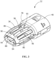
- an electrical connector assembly 10 is electrically and mechanically connected to a cable 12.
- the cable 12 can transfer data between and among storage devices, switches, routers, printed circuit boards (PCBs), analog to digital converters, connectors, and other devices.
- the cable 12 can support data transfer rates of 100 Mbps and higher.
- the cable 12 can support data transfer rates of approximately 4.25 Gbps to approximately 25 Gbps.
- the cable 12 also can be used with data transfer rates above or below these exemplary rates.
- the cable 12 has a cable jacket 14, a braided shield 16, a metalized foil 18 and two center conductors 20, 22. An end of the cable 12 has the cable jacket 14 removed.
- the dielectrics 24, 26 of the conductors 20, 22 are also removed, thereby exposing a portion of the conductors 20, 22.
- the electrical connector assembly 10 has a cable assembly mating end 30 and a cable assembly cable receiving end 31.
- the connector assembly 10 includes a first metallic outer shell 32, a second metallic outer shell 34 and a third metallic outer shell 35.
- the first metallic outer shell 32 has a mating connector receiving portion 36 and a second metallic outer shell receiving portion 40.
- the second metallic outer shell 34 has a first metallic outer shell receiving portion 42 and a conductor transition portion 44.
- a dielectric housing 50 is positioned in the electrical connector assembly 10.
- the housing 50 made of dielectric material.
- the housing 50 has a mating end 52 and an oppositely facing conductor receiving end 54.
- Terminal receiving openings 56 extend from the mating end 52 to the conductor receiving end 54.
- the terminal receiving openings 56 are dimensioned to receive terminals 60 ( FIGS. 2 and 4 ) through the conductor receiving end 54.
- the terminals 60 are electrically connected to the exposed ends of the conductors 20, 22 of the cable 12.
- two terminal receiving openings 56 are provided, however other numbers and configurations of the terminal receiving openings may be used.
- the dielectric housing 50 has mounting projections 70 which extend from side surface 72 thereof.
- the mounting projections each have a first shell engagement surface 74 and a second shell engagement surface 76.
- the dielectric housing 50 When assembled, as shown in FIG. 4 , the dielectric housing 50 is positioned in the mating connector receiving portion 36 and the second metallic outer shell receiving portion 40 of the first metallic outer shell 32.
- the first shell engagement surfaces 74 of the mounting projections 70 engage an inner transition wall 78 of the mating connector receiving portion 36 to properly position the housing 50 and prevent the further movement of the housing 50 into the mating connector receiving portion 36.
- first metallic outer shell receiving portion 42 of the second metallic outer shell 34 is positioned within the second metallic outer shell receiving portion 40 of the first metallic outer shell 32.
- One or more latches 82 of the first metallic outer shell 32 cooperate with one or more openings 84 of the second metallic outer shell 34 to secure the second metallic outer shell 34 to the first metallic outer shell 32.
- the second metallic outer shell 34 is secured to the first metallic outer shell 32 by adhesive, or other know methods of attachment. In this position, the end 80 of the second metallic outer shell 34 engages the second shell engagement surfaces 76 of the mounting projections 70 to properly position the housing 50 and prevent the movement of the housing 50 into the second metallic outer shell 34.
- the terminals 60 of the electrical connector assembly 10 are terminated to ends of the conductors 20, 22 of the cable 12, such as by crimping.
- the terminals 60 are female terminals with receptacle portions 62.
- other configurations of terminals including, but not limited to, female socket terminals, may be used.
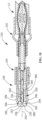
- the mating connector receiving portion 36 of the first metallic outer shell 32 has resilient contact arms 86 which extend from the second metallic outer shell receiving portion 40 to an electrically conductive protection member or portion 88 of the mating connector receiving portion 36.
- the protection member 88 is positioned proximate to and extends from the cable assembly mating end 30.
- the protection member 88 surrounds the mating end 52 of the housing 50, but does not cover the terminal receiving openings 56.
- the protection member 88 has an outer surface 90 which is tapered toward a longitudinal axis 92 of the cable assembly 10. The tapered shape of the outer surface 90 acts as a lead-in surface when a mating connector is mated to the connector assembly 10.
- the resilient contact arms 86 have front ends 94 which are proximate the cable assembly mating end 30 and which cooperate with the protection member 88. As shown in FIG. 3 , the front ends 94 of the resilient contact arms 86 are integrally formed and attached to the protection member 88 of the mating connector receiving portion 36 of the first metallic outer shell 32. Rear ends 95 of the resilient contact arms 86 are positioned away from the cable assembly mating end 30 and are integrally formed and attached to the inner transition wall 78 of the mating connector receiving portion 36. The resilient contact arms 86 are bowed, wherein center sections 96 of the resilient contact arms 86 are spaced further from a longitudinal axis 92 of the cable assembly 10 than the front ends 94 of the resilient contact arms 86 or the protection member 88. In various embodiments, the center sections 96 may have enlarged contact sections which provide a greater surface area to engage the mating connector when the mating connector is mated to the connector assembly 10.
- the use of the resilient contact arms 86 and the bowed center sections 96 provide for increased connection between the mating connector (not shown) and the connector assembly 10.
- the resilient contact arms 86 are supported at both ends, the resilient contact arms 86 provide for enhanced structural integrity of the mating connector receiving portion 36 of the first metallic outer shell 32.
- the bowed center sections 96 of the resilient contact arms 86 engage a cavity (not shown) of the mating connector, causing the bowed center sections 96 to resiliently deform toward the longitudinal axis 92 of the cable assembly 10.
- the bowed center sections 96 resist the inward movement of the bowed center sections 96, thereby causing a force to be applied to the mating connector.
- the fixed front ends 94 and rear ends 95 also cause the center of the bowed center sections 96 to deform more than the ends of the bowed center sections 96, causing the bowed center sections 96 to become flatter, thereby providing more connection points and surfaces for the electrical connection or pathway between the mating connector and the connector assembly 10.
- the entire length of the resilient contact arms 86 and the electrically conductive protection member 88 provide an electrical path thereby facilitating high speed transmission and better EMI performance, in contrast to prior connectors in which the contact arms are fixed or non-deformable and do not connector to an electrically conductive member at both ends, resulting in the contact arm being electrically isolated and therefore, the EMI performance is not enhanced.
- the front ends 94 of the resilient contact arms 86 are integrally attached to the protection member 88, free edges of the front ends 94 are not free or exposed and therefore cannot engage the mating connector as the mating connector is mated to the connector assembly 10.
- the outer surface 90 of the integrally formed protection member 88 acts as a lead-in surface when a mating connector is initially mated to the connector assembly 10 and as the mating connector is moved over the outer surface 90 and the contact arms 86. Stubbing of the mating connector on the resilient contact arms 86 is thereby minimized or prevented.
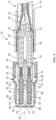
- FIGS. 5 through 7 An embodiment of an electrical connector 110 falling within the scope of the invention is shown in FIGS. 5 through 7 .
- the electrical connector assembly 110 is electrically and mechanically connected to a cable 12.
- the electrical connector assembly 110 has a cable assembly mating end 130 and a cable assembly cable receiving end 131.
- the connector assembly 110 includes a first metallic outer shell 132, a second metallic outer shell 134 and a third metallic outer shell 135.
- the first metallic outer shell 132 has a mating connector receiving portion 136, which is also a housing retention portion, and a second metallic outer shell receiving portion 140.
- the second metallic outer shell 134 has a first metallic outer shell receiving portion 142, a conductor transition portion 144 and a third metallic shell cooperating portion 146.
- a dielectric housing 150 is positioned in the electrical connector assembly 110.
- the housing 150 made of dielectric material. As shown in FIGS. 6 and 7 , the housing 150 has a mating end 152 and an oppositely facing conductor receiving end 154. Terminal receiving openings 156 extend from the mating end 152 to the conductor receiving end 154. The terminal receiving openings 156 are dimensioned to receive terminals 160 ( FIG. 2 ) through the conductor receiving end 154. The terminals 160 are electrically connected to the exposed ends of the conductors 20, 22 of the cable 12. In the embodiment shown, two terminal receiving openings 156 are provided, however other numbers and configurations of the terminal receiving openings may be used.
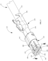
- the dielectric housing 150 has recess 166 which extend from proximate the mating end 152 toward the conductor receiving end 154. Raised projections or areas 167 ( FIG. 7 ) are provided proximate the recesses 166.
- a protection member 188 is provided at the mating end 152 of the housing 150.
- the protection member 188 is made of dielectric material and is integrally molded with the housing 150.
- the protection member 188 surrounds the mating end 152 of the housing 150, but does not cover the terminal receiving openings 156. As shown in FIG. 7 , the protection member 188 has an outer surface 190 with a shoulder 191 which defines a resilient arm receiving cavity 193.
- the mating connector receiving portion 136 of the first metallic outer shell 132 has resilient contact arms 186 which extend from the second metallic outer shell receiving portion 140.
- the resilient contact arms 186 have front ends 194 which are proximate the cable assembly mating end 130 and which cooperate with the protection member 188.
- the front ends 194 of the resilient contact arms 186 have curved or arcuate contact sections 196, wherein curved contact sections 196 of the resilient contact arms 186 are spaced further from a longitudinal axis 192 of the cable assembly 110 than the front ends 194 of the resilient contact arms 186 and the protection member 188.
- the front ends 194 of the resilient contact arms 186 of the first metallic outer shell 132 are resiliently deformed away from the longitudinal axis 192 by the raised areas 167 of the housing 150. Continued insertion allows the front ends 194 to move beyond the raised areas 167, allowing the resilient contact arms 186 to return toward their unstressed position. In this position, the front ends 194 are positioned in the recesses 166, thereby retaining the housing 150 in the first metallic outer shell 132. In this position, the front ends 194 are also positioned in the resilient arm receiving cavity 193 of the protection member 188, with the shoulder 191 positioned over the front ends 194 of the resilient contact arms 186.
- the use of the resilient contact arms 186 and the curved contact sections 196 provides for increased connection between the mating connector (not shown) and the connector assembly 110.
- the free ends 194 of the resilient contact arms 186 are supported by the housing 150, the movement of the resilient contact arms 186 toward the longitudinal axis 192 of the cable assembly 110 is limited, thereby providing for enhanced structural integrity of the mating connector receiving portion 136 of the first metallic outer shell 132.
- the curved contact sections 196 of the resilient contact arms 186 engage a cavity (not shown) of the mating connector, causing the curved contact sections 196 to deform toward the longitudinal axis 192 of the cable assembly 110.
- the curved contact sections 196 are prevented from inward movement, thereby causing a force to be applied by the curved contact sections 196 to the mating connector.
- the curved contact sections 196 are deformed as mating occurs. The deformation of the curved contact sections 196 causes the curved contact sections 196 to become flatter, thereby providing more connection points and surfaces for the electrical connection or pathway between the mating connector and the connector assembly 110.
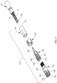
- the electrical connector assembly 210 is electrically and mechanically connected to a cable 12.
- the electrical connector assembly 210 has a cable assembly mating end 230 and a cable assembly cable receiving end 231.
- the connector assembly 210 includes a first metallic outer shell 232 and a second metallic outer shell 234. As shown in FIG. 9 , the first metallic outer shell 232 has a mating connector receiving portion 236 and a second metallic outer shell receiving portion 240.
- the second metallic outer shell 234 has a first metallic outer shell receiving portion 242.
- a dielectric housing 250 is positioned in the electrical connector assembly 210.
- the housing 250 made of dielectric material. As shown in FIGS. 9 and 10 , the housing 250 has a mating end 252 and an oppositely facing conductor receiving end 254. Terminal receiving openings 256 extend from the mating end 252 to the conductor receiving end 254. The terminal receiving openings 256 are dimensioned to receive terminals 260 ( FIG. 9 ) through the conductor receiving end 254. The terminals 260 are electrically connected to the exposed ends of the conductors 20, 22 of the cable 12. In the embodiment shown, two terminal receiving openings 256 are provided, however other numbers and configurations of the terminal receiving openings may be used.
- the dielectric housing 250 has recesses 266 which extend from proximate the mating end 252 toward the conductor receiving end 254. As shown in FIG. 10 , raised projections or areas 267 are provided proximate the recesses 266 A protection member 288 is provided at the mating end 252 of the housing 250.
- the protection member 288 is made of dielectric material and is integrally molded with the housing 250.
- the protection member 288 surrounds the mating end 252 of the housing 250, but does not cover the terminal receiving openings 256.
- the protection member 288 has an outer surface 290 which is tapered toward a longitudinal axis 292 of the cable assembly 10. The tapered shape of the outer surface 290 acts as a lead-in surface when a mating connector is mated to the connector assembly 210.
- the mating connector receiving portion 236 of the first metallic outer shell 232 has resilient contact arms 286 which extend from the second metallic outer shell receiving portion 240.
- the resilient contact arms 286 have front ends 294 which are proximate the cable assembly mating end 230 and which cooperate with the protection member 288. In one embodiment, the front ends 294 are received in recesses 266 of the protection member 288.
- the front ends 294 of the resilient contact arms 286 have curved or arcuate contact sections 296. The curved contact sections 296 of the resilient contact arms 286 are spaced further from a longitudinal axis 292 of the cable assembly 210 than the front ends 294 of the resilient contact arms 286 or the protection member 288.
- the front ends 294 of the resilient contact arms 286 are resiliently deformed away from the longitudinal axis 292 by the housing 250, as the width of the housing 250 is greater than the opening between the front ends 294 of the resilient contact arms 286.
- the front ends 294 continue insertion allows the front ends 294 to move into recesses 266, allowing the resilient contact arms 286 to return toward their unstressed position. In this position, the front ends 294 are positioned in the recesses 266, thereby retaining the housing 250 in the first metallic outer shell 232.
- the use of the resilient contact arms 286 and the curved contact sections 296 provides for increased connection between the mating connector (not shown) and the connector assembly 210.
- the free ends 294 of the resilient contact arms 286 are supported by the housing 250, the movement of the resilient contact arms 286 toward the longitudinal axis 292 of the cable assembly 210 is limited, thereby providing for enhanced structural integrity of the mating connector receiving portion 236 of the first metallic outer shell 232.
- the curved contact sections 296 of the resilient contact arms 286 engage a cavity (not shown) of the mating connector, causing the curved contact sections 296 to deform toward the longitudinal axis 292 of the cable assembly 210.
- the curved contact sections 296 are prevented from inward movement, thereby causing a force to be applied by the curved contact sections 296 to the mating connector.
- the curved contact sections 296 are deformed as mating occurs. The deformation of the curved contact sections 296 causes the curved contact sections 296 to become flatter, thereby providing more connection points and surfaces for the electrical connection or pathway between the mating connector and the connector assembly 210.
Landscapes
- Details Of Connecting Devices For Male And Female Coupling (AREA)
- Coupling Device And Connection With Printed Circuit (AREA)
- Connector Housings Or Holding Contact Members (AREA)
Claims (2)
- Kabelanordnung (110) zum Terminieren eines Kabels, wobei die Kabelanordnung (110) Folgendes umfasst:ein Kabelanordnungs-Verpaarungsende (130) und ein Kabelanordnungs-Kabelaufnahmeende (131);einen metallischen Außenmantel (132), der in der Nähe des Kabelanordnungs-Verpaarungsendes (130) der Kabelanordnung (110) positioniert ist, wobei der metallische Außenmantel (132) einen Verpaarungskontakteingriffsabschnitt (136) hat;ein Gehäuse (150) aus dielektrischem Material, das im metallischen Außenmantel (132) positioniert ist, wobei das Gehäuse (150) ein Gehäuseverpaarungsende (152) und ein entgegengesetzt gerichtetes Gehäuseleiteraufnahmeende (154) hat, wobei sich Klemmenaufnahmeöffnungen (156) vom Gehäuseverpaarungsende (152) erstrecken, wobei sich das Gehäuse (150) von nahe dem Kabelanordnungsverpaarungsende (130) in Richtung des Kabelanordnungs-Kabelaufnahmeendes (131) erstreckt;elastische Kontaktarme (186), die am Verpaarungskontakteingriffsabschnitt (136) des metallischen Außenmantels (132) vorgesehen sind, wobei sich die elastischen Kontaktarme (186) von nahe dem Kabelanordnungsverpaarungsende (130) erstrecken, wobei vordere Enden (194) der elastischen Kontaktarme (186) nahe dem Kabelanordnungsverpaarungsende (130) liegen und mit einem Schutzelement (188) der Kabelanordnung (110) zusammenwirken,wobei das Schutzelement (188) der Kabelanordnung (110) am Gehäuse (150) vorgesehen ist, das Aussparungen (166) zur Aufnahme der elastischen Kontaktarme aufweist, die sich vom Schutzelement (188) in Richtung des Kabelanordnungs-Kabelaufnahmeendes (131) erstrecken, und die vorderen Enden (194) der elastischen Kontaktarme (186) in den Aussparungen (166) zur Aufnahme der elastischen Kontaktarme positioniert sind,dadurch gekennzeichnet, dass das Schutzelement (188) eine Schulter (191) hat, die sich über Abschnitte der Aussparungen (166) zur Aufnahme der elastischen Kontaktarme und die vorderen Enden (194) der elastischen Kontaktarme (186) erstreckt.
- Kabelanordnung (110) nach Anspruch 1, wobei gebogene Verpaarungsanordnungskontaktsektionen (196) in der Nähe der vorderen Enden (194) der elastischen Kontaktarme (186) vorgesehen sind, wobei die gebogenen Verpaarungsanordnungskontaktsektionen (196) weiter von einer Längsachse (192) der Kabelanordnung (110) beabstandet sind als die vorderen Enden (194) der elastischen Kontaktarme (186) und als das Schutzelement (188) des Gehäuses (150).
Priority Applications (1)
| Application Number | Priority Date | Filing Date | Title |
|---|---|---|---|
| EP25150304.1A EP4510392A3 (de) | 2020-02-07 | 2021-02-08 | Schutzelement zum schutz elastischer arme einer kontaktanordnung vor überbäuten |
Applications Claiming Priority (2)
| Application Number | Priority Date | Filing Date | Title |
|---|---|---|---|
| US16/784,626 US10978832B1 (en) | 2020-02-07 | 2020-02-07 | Protection member to protect resilient arms of a contact assembly from stubbing |
| PCT/IB2021/051006 WO2021156843A1 (en) | 2020-02-07 | 2021-02-08 | Protection member to protect resilient arms of a contact assembly from stubbing |
Related Child Applications (1)
| Application Number | Title | Priority Date | Filing Date |
|---|---|---|---|
| EP25150304.1A Division EP4510392A3 (de) | 2020-02-07 | 2021-02-08 | Schutzelement zum schutz elastischer arme einer kontaktanordnung vor überbäuten |
Publications (2)
| Publication Number | Publication Date |
|---|---|
| EP4101034A1 EP4101034A1 (de) | 2022-12-14 |
| EP4101034B1 true EP4101034B1 (de) | 2025-01-08 |
Family
ID=74595333
Family Applications (2)
| Application Number | Title | Priority Date | Filing Date |
|---|---|---|---|
| EP25150304.1A Pending EP4510392A3 (de) | 2020-02-07 | 2021-02-08 | Schutzelement zum schutz elastischer arme einer kontaktanordnung vor überbäuten |
| EP21705267.9A Active EP4101034B1 (de) | 2020-02-07 | 2021-02-08 | Schutzelement zum schutz von federnden armen einer kontaktanordnung gegen anstossen |
Family Applications Before (1)
| Application Number | Title | Priority Date | Filing Date |
|---|---|---|---|
| EP25150304.1A Pending EP4510392A3 (de) | 2020-02-07 | 2021-02-08 | Schutzelement zum schutz elastischer arme einer kontaktanordnung vor überbäuten |
Country Status (7)
| Country | Link |
|---|---|
| US (1) | US10978832B1 (de) |
| EP (2) | EP4510392A3 (de) |
| JP (2) | JP7662208B2 (de) |
| KR (1) | KR102774577B1 (de) |
| CN (1) | CN115336118A (de) |
| MX (2) | MX2022009663A (de) |
| WO (1) | WO2021156843A1 (de) |
Families Citing this family (7)
| Publication number | Priority date | Publication date | Assignee | Title |
|---|---|---|---|---|
| DE102020132011A1 (de) * | 2020-12-02 | 2022-06-02 | Md Elektronik Gmbh | Steckverbinderanordnung |
| US12170424B2 (en) | 2021-08-11 | 2024-12-17 | Te Connectivity Germany Gmbh | Contact of an electrical connector with protection tabs for cantilever beams |
| US20230155326A1 (en) * | 2021-11-12 | 2023-05-18 | Te Connectivity Germany Gmbh | Contact arrangement for a coaxial plug and mutliple contact arrangement |
| US12244114B2 (en) * | 2021-11-16 | 2025-03-04 | Te Connectivity Solutions Gmbh | High deformation and retention ferrule |
| JP2025011421A (ja) * | 2023-07-11 | 2025-01-24 | 株式会社オートネットワーク技術研究所 | シールドコネクタ |
| US20250266648A1 (en) * | 2024-02-21 | 2025-08-21 | Te Connectivity Solutions Gmbh | Shield Contact System |
| FR3165116A1 (fr) * | 2024-07-25 | 2026-01-30 | Raydiall Sas | Corps de blindage électromagnétique pour connecteur de transmission de signaux électriques et/ou de données et/ou de signaux radiofréquences (RF), comprenant des pattes flexibles radialement à deux profils différents dont un à bossage destiné à former un point de contact électrique. |
Family Cites Families (26)
| Publication number | Priority date | Publication date | Assignee | Title |
|---|---|---|---|---|
| US3366920A (en) * | 1965-11-22 | 1968-01-30 | Amp Inc | Coaxial connector |
| US5066249A (en) * | 1990-12-18 | 1991-11-19 | Amp Incorporated | Coaxial subminiature connector |
| GB9406934D0 (en) * | 1994-04-07 | 1994-06-01 | Amp Gmbh | Electrial terminal back-up spring with anti-chattering support members |
| FR2730864B3 (fr) * | 1995-02-17 | 1997-04-30 | Amp France | Borne femelle electrique d'une seule piece |
| JP2006318788A (ja) * | 2005-05-13 | 2006-11-24 | Auto Network Gijutsu Kenkyusho:Kk | シールドコネクタ |
| US7806737B2 (en) * | 2008-02-04 | 2010-10-05 | Methode Electronics, Inc. | Stamped beam connector |
| DE202012007577U1 (de) | 2012-08-07 | 2012-09-13 | Rosenberger Hochfrequenztechnik Gmbh & Co. Kg | Steckverbinder |
| DE202012008961U1 (de) | 2012-09-17 | 2012-10-12 | Rosenberger Hochfrequenztechnik Gmbh & Co. Kg | Kontaktelement |
| CN203150752U (zh) * | 2013-01-31 | 2013-08-21 | 和锲精密电子股份有限公司 | 电源连接器 |
| DE202013006297U1 (de) | 2013-07-11 | 2013-07-25 | Rosenberger Hochfrequenztechnik Gmbh & Co. Kg | Steckverbinder |
| DE202014003291U1 (de) | 2014-04-16 | 2014-07-04 | Rosenberger Hochfrequenztechnik Gmbh & Co. Kg | Kabelanordnung |
| DE102014006244A1 (de) | 2014-04-28 | 2015-10-29 | Rosenberger Hochfrequenztechnik Gmbh & Co. Kg | Crimp-Schweißverbindung |
| DE202015000750U1 (de) | 2015-01-30 | 2015-02-25 | Rosenberger Hochfrequenztechnik Gmbh & Co. Kg | Steckverbinderanordnung mit Kompensationshülse |
| DE102015004485B4 (de) | 2015-04-07 | 2016-12-15 | Rosenberger Hochfrequenztechnik Gmbh & Co. Kg | Verfahren zum Herstellen einer Steckverbinderanordnung |
| US10541488B2 (en) | 2016-02-26 | 2020-01-21 | Rosenberger Hochfrequenztechnik Gmbh | Outer conductor arrangement for a coaxial plug connector |
| WO2017144069A1 (de) | 2016-02-26 | 2017-08-31 | Rosenberger Hochfrequenztechnik Gmbh & Co. Kg | Kontakthülse für einen elektrischen steckverbinder |
| JP7005507B2 (ja) | 2016-02-26 | 2022-01-21 | ローゼンベルガー ホーフフレクベンツテクニーク ゲーエムベーハー ウント ツェーオー カーゲー | 電気プラグコネクタ |
| KR102075283B1 (ko) | 2016-02-26 | 2020-03-02 | 로젠버거 호흐프리쿠벤츠테흐닉 게엠베하 운트 코. 카게 | Hf 플러그 연결부 |
| DE102016003134A1 (de) | 2016-03-15 | 2017-09-21 | Rosenberger Hochfrequenztechnik Gmbh & Co. Kg | Kabel zum Übertragen von elektrischen Signalen |
| DE102016109266A1 (de) | 2016-05-06 | 2017-11-09 | Rosenberger Hochfrequenztechnik Gmbh & Co. Kg | Steckverbindungsvorrichtung mit wenigstens einem Steckverbinder |
| EP3396793B1 (de) * | 2017-04-28 | 2020-08-26 | Rosenberger Hochfrequenztechnik GmbH & Co. KG | Kontaktkörper für einen steckverbinder |
| JP6913524B2 (ja) * | 2017-06-14 | 2021-08-04 | モレックス エルエルシー | 同軸コネクタ |
| FR3074614B1 (fr) * | 2017-12-06 | 2019-11-01 | Raydiall | Connecteur pour cable a fils electriques isoles, comprenant un corps logeant des contacts centraux en saillie et deux demi-coques assemblees entre elles autour du corps et des contacts sertis sur les fils |
| FR3074616B1 (fr) * | 2017-12-06 | 2019-11-01 | Raydiall | Piece d'adaptation d'impedance electrique pour connecteur monte sur cable a fils electriques isoles |
| DE102018102564A1 (de) * | 2018-02-06 | 2019-08-08 | Te Connectivity Germany Gmbh | Elektrische Ferrule, elektrische Verbindungseinrichtung, sowie Verfahren zum Konfektionieren eines elektrischen Kabels |
| JP7357912B2 (ja) | 2019-09-24 | 2023-10-10 | 日本圧着端子製造株式会社 | 同軸コネクタ |
-
2020
- 2020-02-07 US US16/784,626 patent/US10978832B1/en active Active
-
2021
- 2021-02-08 MX MX2022009663A patent/MX2022009663A/es unknown
- 2021-02-08 JP JP2022547190A patent/JP7662208B2/ja active Active
- 2021-02-08 WO PCT/IB2021/051006 patent/WO2021156843A1/en not_active Ceased
- 2021-02-08 EP EP25150304.1A patent/EP4510392A3/de active Pending
- 2021-02-08 CN CN202180012776.3A patent/CN115336118A/zh active Pending
- 2021-02-08 KR KR1020227030794A patent/KR102774577B1/ko active Active
- 2021-02-08 EP EP21705267.9A patent/EP4101034B1/de active Active
-
2022
- 2022-08-05 MX MX2025004153A patent/MX2025004153A/es unknown
-
2025
- 2025-03-24 JP JP2025048323A patent/JP2025098131A/ja active Pending
Also Published As
| Publication number | Publication date |
|---|---|
| JP2023513119A (ja) | 2023-03-30 |
| KR20220133292A (ko) | 2022-10-04 |
| WO2021156843A1 (en) | 2021-08-12 |
| MX2025004153A (es) | 2025-05-02 |
| US10978832B1 (en) | 2021-04-13 |
| EP4101034A1 (de) | 2022-12-14 |
| EP4510392A3 (de) | 2025-05-07 |
| KR102774577B1 (ko) | 2025-03-04 |
| JP7662208B2 (ja) | 2025-04-15 |
| JP2025098131A (ja) | 2025-07-01 |
| CN115336118A (zh) | 2022-11-11 |
| EP4510392A2 (de) | 2025-02-19 |
| MX2022009663A (es) | 2022-09-09 |
Similar Documents
| Publication | Publication Date | Title |
|---|---|---|
| EP4101034B1 (de) | Schutzelement zum schutz von federnden armen einer kontaktanordnung gegen anstossen | |
| US6582252B1 (en) | Termination connector assembly with tight angle for shielded cable | |
| US5454734A (en) | Electrical connection system | |
| US10777936B2 (en) | Electrical device having a ground termination component with strain relief | |
| US20040259421A1 (en) | Cable connector assembly having improved shield members | |
| GB2257851A (en) | Shielded connector. | |
| US12003061B2 (en) | Ground structure for a cable card assembly of an electrical connector | |
| US6065998A (en) | Electrical connector for coaxial cable | |
| EP4104256B1 (de) | Impedanzkontrollstecker | |
| US20040266266A1 (en) | Cable end connector assembly with a shield device | |
| EP0542075B1 (de) | Verfahren zum Anschliessen eines elektrischen koaxialen Miniatursteckers und sich daraus ergebender Steckeranschluss | |
| JP7772308B2 (ja) | インピーダンス制御のための誘電体クラムシェルコネクタを備えるケーブルアセンブリ | |
| JP7751137B2 (ja) | 電気ケーブルの編組位置決めクリップ | |
| US11811171B2 (en) | Cable termination for an electrical connector | |
| US6106334A (en) | Shielded cable connector | |
| EP1410469B1 (de) | Steckverbinder für eine mehrzahl von anschlussbuchsen für koaxialkabel | |
| US20220271476A1 (en) | Ground structure for a cable card assembly of an electrical connector |
Legal Events
| Date | Code | Title | Description |
|---|---|---|---|
| STAA | Information on the status of an ep patent application or granted ep patent |
Free format text: STATUS: UNKNOWN |
|
| STAA | Information on the status of an ep patent application or granted ep patent |
Free format text: STATUS: THE INTERNATIONAL PUBLICATION HAS BEEN MADE |
|
| PUAI | Public reference made under article 153(3) epc to a published international application that has entered the european phase |
Free format text: ORIGINAL CODE: 0009012 |
|
| STAA | Information on the status of an ep patent application or granted ep patent |
Free format text: STATUS: REQUEST FOR EXAMINATION WAS MADE |
|
| 17P | Request for examination filed |
Effective date: 20220905 |
|
| AK | Designated contracting states |
Kind code of ref document: A1 Designated state(s): AL AT BE BG CH CY CZ DE DK EE ES FI FR GB GR HR HU IE IS IT LI LT LU LV MC MK MT NL NO PL PT RO RS SE SI SK SM TR |
|
| DAV | Request for validation of the european patent (deleted) | ||
| DAX | Request for extension of the european patent (deleted) | ||
| GRAP | Despatch of communication of intention to grant a patent |
Free format text: ORIGINAL CODE: EPIDOSNIGR1 |
|
| STAA | Information on the status of an ep patent application or granted ep patent |
Free format text: STATUS: GRANT OF PATENT IS INTENDED |
|
| INTG | Intention to grant announced |
Effective date: 20240808 |
|
| GRAS | Grant fee paid |
Free format text: ORIGINAL CODE: EPIDOSNIGR3 |
|
| GRAA | (expected) grant |
Free format text: ORIGINAL CODE: 0009210 |
|
| STAA | Information on the status of an ep patent application or granted ep patent |
Free format text: STATUS: THE PATENT HAS BEEN GRANTED |
|
| AK | Designated contracting states |
Kind code of ref document: B1 Designated state(s): AL AT BE BG CH CY CZ DE DK EE ES FI FR GB GR HR HU IE IS IT LI LT LU LV MC MK MT NL NO PL PT RO RS SE SI SK SM TR |
|
| REG | Reference to a national code |
Ref country code: GB Ref legal event code: FG4D |
|
| REG | Reference to a national code |
Ref country code: CH Ref legal event code: EP |
|
| REG | Reference to a national code |
Ref country code: DE Ref legal event code: R096 Ref document number: 602021024642 Country of ref document: DE |
|
| REG | Reference to a national code |
Ref country code: IE Ref legal event code: FG4D |
|
| PGFP | Annual fee paid to national office [announced via postgrant information from national office to epo] |
Ref country code: AT Payment date: 20250417 Year of fee payment: 5 |
|
| REG | Reference to a national code |
Ref country code: LT Ref legal event code: MG9D |
|
| REG | Reference to a national code |
Ref country code: NL Ref legal event code: MP Effective date: 20250108 |
|
| REG | Reference to a national code |
Ref country code: AT Ref legal event code: MK05 Ref document number: 1758958 Country of ref document: AT Kind code of ref document: T Effective date: 20250108 |
|
| PG25 | Lapsed in a contracting state [announced via postgrant information from national office to epo] |
Ref country code: NL Free format text: LAPSE BECAUSE OF FAILURE TO SUBMIT A TRANSLATION OF THE DESCRIPTION OR TO PAY THE FEE WITHIN THE PRESCRIBED TIME-LIMIT Effective date: 20250108 |
|
| PG25 | Lapsed in a contracting state [announced via postgrant information from national office to epo] |
Ref country code: RS Free format text: LAPSE BECAUSE OF FAILURE TO SUBMIT A TRANSLATION OF THE DESCRIPTION OR TO PAY THE FEE WITHIN THE PRESCRIBED TIME-LIMIT Effective date: 20250408 |
|
| PG25 | Lapsed in a contracting state [announced via postgrant information from national office to epo] |
Ref country code: FI Free format text: LAPSE BECAUSE OF FAILURE TO SUBMIT A TRANSLATION OF THE DESCRIPTION OR TO PAY THE FEE WITHIN THE PRESCRIBED TIME-LIMIT Effective date: 20250108 |
|
| PG25 | Lapsed in a contracting state [announced via postgrant information from national office to epo] |
Ref country code: PL Free format text: LAPSE BECAUSE OF FAILURE TO SUBMIT A TRANSLATION OF THE DESCRIPTION OR TO PAY THE FEE WITHIN THE PRESCRIBED TIME-LIMIT Effective date: 20250108 |
|
| PG25 | Lapsed in a contracting state [announced via postgrant information from national office to epo] |
Ref country code: ES Free format text: LAPSE BECAUSE OF FAILURE TO SUBMIT A TRANSLATION OF THE DESCRIPTION OR TO PAY THE FEE WITHIN THE PRESCRIBED TIME-LIMIT Effective date: 20250108 |
|
| PG25 | Lapsed in a contracting state [announced via postgrant information from national office to epo] |
Ref country code: NO Free format text: LAPSE BECAUSE OF FAILURE TO SUBMIT A TRANSLATION OF THE DESCRIPTION OR TO PAY THE FEE WITHIN THE PRESCRIBED TIME-LIMIT Effective date: 20250408 Ref country code: IS Free format text: LAPSE BECAUSE OF FAILURE TO SUBMIT A TRANSLATION OF THE DESCRIPTION OR TO PAY THE FEE WITHIN THE PRESCRIBED TIME-LIMIT Effective date: 20250508 |
|
| PG25 | Lapsed in a contracting state [announced via postgrant information from national office to epo] |
Ref country code: HR Free format text: LAPSE BECAUSE OF FAILURE TO SUBMIT A TRANSLATION OF THE DESCRIPTION OR TO PAY THE FEE WITHIN THE PRESCRIBED TIME-LIMIT Effective date: 20250108 |
|
| PG25 | Lapsed in a contracting state [announced via postgrant information from national office to epo] |
Ref country code: PT Free format text: LAPSE BECAUSE OF FAILURE TO SUBMIT A TRANSLATION OF THE DESCRIPTION OR TO PAY THE FEE WITHIN THE PRESCRIBED TIME-LIMIT Effective date: 20250508 Ref country code: LV Free format text: LAPSE BECAUSE OF FAILURE TO SUBMIT A TRANSLATION OF THE DESCRIPTION OR TO PAY THE FEE WITHIN THE PRESCRIBED TIME-LIMIT Effective date: 20250108 |
|
| PG25 | Lapsed in a contracting state [announced via postgrant information from national office to epo] |
Ref country code: GR Free format text: LAPSE BECAUSE OF FAILURE TO SUBMIT A TRANSLATION OF THE DESCRIPTION OR TO PAY THE FEE WITHIN THE PRESCRIBED TIME-LIMIT Effective date: 20250409 Ref country code: BG Free format text: LAPSE BECAUSE OF FAILURE TO SUBMIT A TRANSLATION OF THE DESCRIPTION OR TO PAY THE FEE WITHIN THE PRESCRIBED TIME-LIMIT Effective date: 20250108 |
|
| PG25 | Lapsed in a contracting state [announced via postgrant information from national office to epo] |
Ref country code: AT Free format text: LAPSE BECAUSE OF FAILURE TO SUBMIT A TRANSLATION OF THE DESCRIPTION OR TO PAY THE FEE WITHIN THE PRESCRIBED TIME-LIMIT Effective date: 20250108 |
|
| PG25 | Lapsed in a contracting state [announced via postgrant information from national office to epo] |
Ref country code: SE Free format text: LAPSE BECAUSE OF FAILURE TO SUBMIT A TRANSLATION OF THE DESCRIPTION OR TO PAY THE FEE WITHIN THE PRESCRIBED TIME-LIMIT Effective date: 20250108 |
|
| REG | Reference to a national code |
Ref country code: CH Ref legal event code: PL |
|
| PG25 | Lapsed in a contracting state [announced via postgrant information from national office to epo] |
Ref country code: SM Free format text: LAPSE BECAUSE OF FAILURE TO SUBMIT A TRANSLATION OF THE DESCRIPTION OR TO PAY THE FEE WITHIN THE PRESCRIBED TIME-LIMIT Effective date: 20250108 |
|
| REG | Reference to a national code |
Ref country code: DE Ref legal event code: R097 Ref document number: 602021024642 Country of ref document: DE |
|
| PG25 | Lapsed in a contracting state [announced via postgrant information from national office to epo] |
Ref country code: DK Free format text: LAPSE BECAUSE OF FAILURE TO SUBMIT A TRANSLATION OF THE DESCRIPTION OR TO PAY THE FEE WITHIN THE PRESCRIBED TIME-LIMIT Effective date: 20250108 |
|
| PG25 | Lapsed in a contracting state [announced via postgrant information from national office to epo] |
Ref country code: MC Free format text: LAPSE BECAUSE OF FAILURE TO SUBMIT A TRANSLATION OF THE DESCRIPTION OR TO PAY THE FEE WITHIN THE PRESCRIBED TIME-LIMIT Effective date: 20250108 |
|
| PG25 | Lapsed in a contracting state [announced via postgrant information from national office to epo] |
Ref country code: LU Free format text: LAPSE BECAUSE OF NON-PAYMENT OF DUE FEES Effective date: 20250208 |
|
| PG25 | Lapsed in a contracting state [announced via postgrant information from national office to epo] |
Ref country code: CH Free format text: LAPSE BECAUSE OF NON-PAYMENT OF DUE FEES Effective date: 20250228 |
|
| PG25 | Lapsed in a contracting state [announced via postgrant information from national office to epo] |
Ref country code: CZ Free format text: LAPSE BECAUSE OF FAILURE TO SUBMIT A TRANSLATION OF THE DESCRIPTION OR TO PAY THE FEE WITHIN THE PRESCRIBED TIME-LIMIT Effective date: 20250108 Ref country code: EE Free format text: LAPSE BECAUSE OF FAILURE TO SUBMIT A TRANSLATION OF THE DESCRIPTION OR TO PAY THE FEE WITHIN THE PRESCRIBED TIME-LIMIT Effective date: 20250108 |
|
| PG25 | Lapsed in a contracting state [announced via postgrant information from national office to epo] |
Ref country code: RO Free format text: LAPSE BECAUSE OF FAILURE TO SUBMIT A TRANSLATION OF THE DESCRIPTION OR TO PAY THE FEE WITHIN THE PRESCRIBED TIME-LIMIT Effective date: 20250108 |
|
| PG25 | Lapsed in a contracting state [announced via postgrant information from national office to epo] |
Ref country code: SK Free format text: LAPSE BECAUSE OF FAILURE TO SUBMIT A TRANSLATION OF THE DESCRIPTION OR TO PAY THE FEE WITHIN THE PRESCRIBED TIME-LIMIT Effective date: 20250108 |
|
| PLBE | No opposition filed within time limit |
Free format text: ORIGINAL CODE: 0009261 |
|
| STAA | Information on the status of an ep patent application or granted ep patent |
Free format text: STATUS: NO OPPOSITION FILED WITHIN TIME LIMIT |
|
| REG | Reference to a national code |
Ref country code: BE Ref legal event code: MM Effective date: 20250228 |
|
| 26N | No opposition filed |
Effective date: 20251009 |
|
| GBPC | Gb: european patent ceased through non-payment of renewal fee |
Effective date: 20250408 |
|
| PG25 | Lapsed in a contracting state [announced via postgrant information from national office to epo] |
Ref country code: GB Free format text: LAPSE BECAUSE OF NON-PAYMENT OF DUE FEES Effective date: 20250408 |
|
| PG25 | Lapsed in a contracting state [announced via postgrant information from national office to epo] |
Ref country code: FR Free format text: LAPSE BECAUSE OF NON-PAYMENT OF DUE FEES Effective date: 20250308 |
|
| PG25 | Lapsed in a contracting state [announced via postgrant information from national office to epo] |
Ref country code: BE Free format text: LAPSE BECAUSE OF NON-PAYMENT OF DUE FEES Effective date: 20250228 |
|
| PG25 | Lapsed in a contracting state [announced via postgrant information from national office to epo] |
Ref country code: IE Free format text: LAPSE BECAUSE OF NON-PAYMENT OF DUE FEES Effective date: 20250208 |
|
| PG25 | Lapsed in a contracting state [announced via postgrant information from national office to epo] |
Ref country code: IT Free format text: LAPSE BECAUSE OF FAILURE TO SUBMIT A TRANSLATION OF THE DESCRIPTION OR TO PAY THE FEE WITHIN THE PRESCRIBED TIME-LIMIT Effective date: 20250108 |
|
| PGFP | Annual fee paid to national office [announced via postgrant information from national office to epo] |
Ref country code: DE Payment date: 20251216 Year of fee payment: 6 |