EP4100916B1 - Activation de caméra monoculaire pour localisation basée sur des données provenant d'un capteur de profondeur - Google Patents
Activation de caméra monoculaire pour localisation basée sur des données provenant d'un capteur de profondeur Download PDFInfo
- Publication number
- EP4100916B1 EP4100916B1 EP20704011.4A EP20704011A EP4100916B1 EP 4100916 B1 EP4100916 B1 EP 4100916B1 EP 20704011 A EP20704011 A EP 20704011A EP 4100916 B1 EP4100916 B1 EP 4100916B1
- Authority
- EP
- European Patent Office
- Prior art keywords
- localization
- monocular camera
- depth
- activating
- benefit level
- Prior art date
- Legal status (The legal status is an assumption and is not a legal conclusion. Google has not performed a legal analysis and makes no representation as to the accuracy of the status listed.)
- Active
Links
Images



Classifications
-
- G—PHYSICS
- G06—COMPUTING OR CALCULATING; COUNTING
- G06T—IMAGE DATA PROCESSING OR GENERATION, IN GENERAL
- G06T7/00—Image analysis
- G06T7/70—Determining position or orientation of objects or cameras
- G06T7/73—Determining position or orientation of objects or cameras using feature-based methods
-
- G—PHYSICS
- G01—MEASURING; TESTING
- G01S—RADIO DIRECTION-FINDING; RADIO NAVIGATION; DETERMINING DISTANCE OR VELOCITY BY USE OF RADIO WAVES; LOCATING OR PRESENCE-DETECTING BY USE OF THE REFLECTION OR RERADIATION OF RADIO WAVES; ANALOGOUS ARRANGEMENTS USING OTHER WAVES
- G01S17/00—Systems using the reflection or reradiation of electromagnetic waves other than radio waves, e.g. lidar systems
- G01S17/88—Lidar systems specially adapted for specific applications
- G01S17/89—Lidar systems specially adapted for specific applications for mapping or imaging
- G01S17/894—Three-dimensional [3D] imaging with simultaneous measurement of time-of-flight at a two-dimensional [2D] array of receiver pixels, e.g. time-of-flight cameras or flash lidar
-
- G—PHYSICS
- G06—COMPUTING OR CALCULATING; COUNTING
- G06T—IMAGE DATA PROCESSING OR GENERATION, IN GENERAL
- G06T7/00—Image analysis
- G06T7/50—Depth or shape recovery
-
- H—ELECTRICITY
- H04—ELECTRIC COMMUNICATION TECHNIQUE
- H04N—PICTORIAL COMMUNICATION, e.g. TELEVISION
- H04N23/00—Cameras or camera modules comprising electronic image sensors; Control thereof
- H04N23/60—Control of cameras or camera modules
- H04N23/66—Remote control of cameras or camera parts, e.g. by remote control devices
-
- G—PHYSICS
- G06—COMPUTING OR CALCULATING; COUNTING
- G06T—IMAGE DATA PROCESSING OR GENERATION, IN GENERAL
- G06T2207/00—Indexing scheme for image analysis or image enhancement
- G06T2207/10—Image acquisition modality
- G06T2207/10028—Range image; Depth image; 3D point clouds
-
- G—PHYSICS
- G06—COMPUTING OR CALCULATING; COUNTING
- G06T—IMAGE DATA PROCESSING OR GENERATION, IN GENERAL
- G06T2207/00—Indexing scheme for image analysis or image enhancement
- G06T2207/30—Subject of image; Context of image processing
- G06T2207/30241—Trajectory
-
- G—PHYSICS
- G06—COMPUTING OR CALCULATING; COUNTING
- G06T—IMAGE DATA PROCESSING OR GENERATION, IN GENERAL
- G06T2207/00—Indexing scheme for image analysis or image enhancement
- G06T2207/30—Subject of image; Context of image processing
- G06T2207/30244—Camera pose
Definitions
- the present disclosure relates to a device for performing localization using one or both of a depth sensor and a monocular camera that are transportable with the device, a method by a device for performing localization using one or both of a depth sensor and a monocular camera that are transportable with the device, and a corresponding computer program product.
- Localization and mapping algorithms such as Simultaneous localization and mapping (SLAM) algorithms, are a technology that allows devices to localize themselves in an environment while relying on onboard sensors such as cameras, range sensors, inertial sensors among others. This is essential for robots to navigate and understand an environment to perform a task, as well as for enabling realistic and persistent content to be displayed in mixed reality devices.
- SLAM Simultaneous localization and mapping
- RGB and IMU sensors Several SLAM algorithms have been proposed which rely on RGB and IMU sensors, depth sensors or a combination of all of these.
- a reason for using a combination of different types of sensors is to leverage unique operational advantages of the differing sensors, and to improve on their individual limitations. For example, an RGB camera performs poorly in a dark or too bright environment since visual features are hard or impossible to acquire in such environments, where a depth camera such as a LIDAR or active stereo camera would perform well in such scenarios.
- a depth camera such as a LIDAR or active stereo camera would perform well in such scenarios.
- the localization and mapping may be performed with higher accuracy and may capture a larger amount of information of the environment (e.g. construction of a dense map instead of a sparse map), among other benefits.
- US 2020/0033127 Al discloses a mechanism that enables the balance between the satisfaction of measurement accuracy required for an application and the suppression of power consumption.
- An information processing apparatus which includes: a control unit configured to acquire information indicating required accuracy of measurement information based on a result of detection by a sensor from an application that uses the measurement information, and control the sensor on the basis of the information indicating the required accuracy.
- the benefit level of activating the monocular camera for localization is determined based on: converting the depth data, which represents a 3-dimensional (3D) localization map, to 2-dimensional (2D) depth data representing a 2D depth image, generating an approximation of depth information that can be acquired from the monocular camera if activated, based on the 2D depth image, and determining the benefit level of activating the monocular camera for localization based on the approximation of depth information.
- Potential advantages of one or more of these embodiments may include that the device is able to determine using depth data from a depth sensor when a monocular camera can provide a sufficient benefit level such that it should be activated from a deactivated state for subsequent use in localization. In this manner, the monocular camera does not have to already be activate in order to programmatically determine whether it would provide a sufficient benefit level for use in localization to justify its activation and use. These operations can reduce the energy consumption and computational resource utilization of the device when performing localization.
- Figure 1 illustrates operations that convert three-dimensional (3D) depth data 100 from a depth sensor, such as LIDAR, to a two-dimensional (2D) depth image 102.
- the 2D depth image 102 can then be processed to determine the benefit level that can be obtained by activating a monocular camera for use in localization, in accordance with some embodiments.
- An estimate of the image that can be captured by the monocular camera, such as an RGB camera, can be extracted from the 3D depth data 100 by converting the 3D depth data 100 into the 2D depth image 102 using intrinsic parameters of the depth camera.
- Potential advantages of one or more of these embodiments may include that the device is able to determine based on the 3D depth data 100 received from the depth sensor when a monocular camera can provide a sufficient benefit level that it should be activated from a deactivated state for use in localization. In this manner, the monocular camera does not have to already be activated in order to programmatically determine whether it would provide a sufficient benefit level for use in localization. These operations can reduce the energy consumption and computational resource utilization of the device when performing localization.
- the following operations can be performed to determine whether the benefit level of activating the monocular camera is sufficient to trigger its activation, and which may further determine whether the depth sensor should be deactivated:
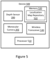
- Figure 5 illustrates a block diagram of components of an example device 500 that are configured in accordance with some embodiments of the present disclosure.
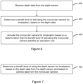
- Figure 6 illustrate a flowchart of operations that may be performed by the device 500 to control activation of a monocular camera 202 for localization based on a determination that the benefit level of activating the monocular camera 202 for localization satisfies an activation rule, in accordance with some embodiments of the present disclosure.
- the device 500 includes at least one processor 510 (hereinafter “processor”) operationally connected to a depth sensor 200, a monocular camera 202, and at least one memory 520 (hereinafter “memory”) storing program code that is executed by the processor 510 to perform operations to receive 600 depth data from the depth sensor 200, determine 602 based on the depth data a benefit level of activating the monocular camera 202 for localization, and activate 604 the monocular camera 202 for localization based on a determination that the benefit level of activating the monocular camera 202 satisfies an activation rule.
- the memory 520 may include a localization map repository 522 (e.g., historical local map) which may be used as explained below.
- the device 500 may include a wireless transceiver 530 that is configured to communicate through a wireless interface.
- the depth sensor 200 and the monocular camera 202 are transportable with the device 500 but are not necessarily part of the device 500.
- the device 500 includes the depth sensor 200, the monocular camera 202, the processor 510, and the memory 520, in some embodiments one or more of these components may be separate from the device 500 and communicatively connected thereto through the wireless transceiver 530 and/or a wired interface.
- the device 500 can be, but is not limited to, a component of any of a smartphone, wearable computer, augmented reality headset, virtual reality headset, mixed reality headset, semi-autonomous or autonomous vehicle, drone, aircraft, robot, etc.
- the "monocular camera” may correspond to a set of monocular cameras
- the "depth sensor” may correspond to a set of depth sensors.
- a set of sensors may contain homogeneous or non-homogenous types of sensors.
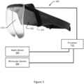
- the MR headset 300 includes a lens 310 through which a user who is wearing the MR headset can view real-world features.
- the MR headset 300 further includes a holder 321 that is configured to releasably retain the mobile electronic device 320 in a defined orientation relative to the lens 310 so that images displayed on a display device of the mobile electronic device 320 are reflected by the lens 310 directly or indirectly toward the user's eyes.
- the MR headset 300 may include intervening mirrors that are positioned between the lens 310 and the user's eyes and, hence, the light may be reflected directly or indirectly toward the user's eyes and/or the camera 202.
- the sensor activation and deactivation logic 204 may also be configured to deactivate the depth sensor 200 based on a determination that the benefit level of using the depth sensor 200 for localization satisfies a deactivation rule, such as when the monocular camera 202 has become activated for localization and when continued use of the depth sensor 200 does not provide sufficient continued benefit. While the monocular camera 202 is active, image data is provided from the monocular camera 202 to a localization algorithm, such as a localization and mapping algorithm 212. Similarly while the depth sensor 200 is active, depth data is provided from the depth sensor 200 to the localization algorithm, such as the localization and mapping algorithm 212.
- the sensor activation and deactivation logic 204 controls switch logic 208 that performs deactivation and activation of selected ones of the sensors 200 and 202.
- the switch logic 208 can perform activation of a sensor (i.e., the depth sensor 200 or the monocular camera 202) by triggering at least one of transitioning the sensor to a higher power state, powering-on the sensor, increasing a data sampling rate of the sensor to a level which is used for localization, increasing resolution of the sensor to a level which is used for localization, changing an optical parameter (e.g., focal length, field of view, etc.) to what is used for localization, and adapting the localization algorithm to use parameters (e.g., optical parameters) of the sensor.
- a sensor i.e., the depth sensor 200 or the monocular camera 202
- the switch logic 208 can perform activation of a sensor (i.e., the depth sensor 200 or the monocular camera 202) by triggering at least one of transitioning the sensor to a higher power state, powering
- the switch logic 208 can perform deactivation of the sensor by triggering at least one of transitioning the sensor to a lower power state, powering-off the sensor, decreasing a data sampling rate of the sensor to a level below what is used for localization, decreasing resolution of the sensor to a level which is below what is used for localization, changing an optical parameter (e.g., focal length, field of view, etc.) to what is not used for localization, and adapting the localization algorithm to cease using parameters (e.g., optical parameters) of the sensor.
- the term "switch" is not constrained to an off-on switch but alternatively or additionally can include control logic that performs one or more of the more complex above-activities for activating and deactivating sensors.
- the monocular camera 202 In order for the monocular camera 202 to provide image data that can be used for localization operations and/or combined localization and mapping operations, e.g., SLAM, the monocular camera 202 has to be able to capture relevant environmental features.
- Various alternative embodiments of operations will now be explained that can determine the benefit level of activating the monocular camera based on the performance of a localization algorithm, such as the localization and mapping algorithm 212.
- the benefit level of activating the monocular camera 202 is determined based on sampling and analyzing the 3D depth data 100 after conversion to a 2D depth image 102, as illustrated in Figure 1 .
- the benefit level of activating the monocular camera 202 for localization is determined 602 based on converting the depth data, which represents a 3D localization map 210, to 2D depth data representing a 2D depth image 102, and generating an approximation of depth information that can be acquired from the monocular camera 202 if activated, based on the 2D depth image 102.
- the benefit level of activating the monocular camera 200 for localization is then determined based on the approximation of depth information.
- the 2D depth image 102 is generated as an approximation of the information that would be required by the monocular camera 202 if activated.
- the approximation may be performed more accurately by repeating the conversion for a sequence of 3D depth data 100 into a sequence of 2D depth images 102 from different perspectives. This may correspond to taking snapshots of the 3D depth data 100, depicted as a 3D depth data, from different perspectives.
- FIG. 9 Corresponding operations are illustrated in Figure 9 , which are configured in accordance with some embodiments of the present disclosure.
- operations repeat 900 the conversion of the depth data representing the perspective in the 3D localization map 210 to the 2D depth data representing the 2D depth image 102.
- the generation of the approximation of depth information is performed based on the 2D depth data for the plurality of different perspectives in the 3D localization map 210.
- the benefit level of activating the monocular camera 202 for localization can be determined 602 based on sampling and analyzing the 3D depth data 100 contained in the localization map 210 currently being used by the depth camera 200 to perform localization.
- the determination 602 of the benefit level of activating the monocular camera for localization can include determining location of the monocular camera based on the depth data.
- a historical 3D localization map repository which may correspond to the localization map repository 522 shown in Figure 5 , is accessed using the location of the monocular camera 202 to obtain historical depth data.
- the historical depth data which represents a historical 3D localization map, is converted to historical 2D depth data representing a historical 2D depth image.
- An approximation of depth information that can be acquired from the monocular camera 202 if activated, is generated based on the historical 2D depth image.
- the benefit level is then determined based on the approximation of depth information.
- the benefit level of activating the monocular camera 202 is determined using a historical 3D localization map (e.g., within repository 522 in Fig. 5 ) and a present trajectory of the monocular camera 202 relative to locations in the historical 3D localization map.
- a historical 3D localization map e.g., within repository 522 in Fig. 5
- a present trajectory of the monocular camera 202 relative to locations in the historical 3D localization map e.g., within repository 522 in Fig. 5
- Example operations are described in the context of Figures 4 and 10 .
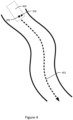
- Figure 4 illustrates a top-view of a device 400 with a depth sensor 200 and a monocular camera 202 moving through an environment along a predicted trajectory 402.
- the operations repeat 1000 the conversion of the historical depth data representing the perspective in the historical 3D localization map to the historical 2D depth data representing the historical 2D depth image 102.
- the generation of the approximation of depth information is performed based on the historical 2D depth data for the plurality of different perspectives along the predicted motion trajectory 402 of the monocular camera 202 relative to the historical 3D localization map.
- the device 500 determines its current pose with respect to the historical 3D localization map being used for localization, and knowledge of direction of motion of the device 500. Given this information, the operations obtain 2D depth images 102 for different perspectives within the historical 3D localization map corresponding to an estimate of the motion trajectory 402 and perform similar operations as detailed in the previous embodiment. For every chosen perspective, the operations can determine the benefit level of activating the monocular camera 202 for localization. Hence, instead of using only online data presently captured from the depth sensor 200, the operations can additionally rely on depth data captured apriori and stored in the historical 3D localization map.
- the minimum number of required feature descriptors to be extracted from the images of the monocular camera 202 may depend on the localization algorithm that is used and the quality of the inferred feature descriptors. For example, the operations may be configured to require a minimum of 6 feature descriptors meeting a quality threshold. However, in order to handle noise when detecting and computing the pose of the features, a larger number of feature descriptors should be detected.
- the monocular camera 202 should be activated if a function of the benefit level obtained over a set of measurements, for example the average of the last N measurements with the depth sensor 200, is above an activation threshold.
- the monocular camera 202 should be activated when the benefit level determined over a set of measurements performed on the localization map (e.g. within the localization map repository 522 in Fig. 5 ), using a measurement for the current pose of the device 400 and the predicted pose of the device 400 along the future motion trajectory 402 , is above the activation threshold.
- the determination of whether the benefit level of activating the monocular camera 202 satisfies an activation rule can be based on the energy budget 206 of the device. For example, if the above conditions are satisfied for the benefit level of activating monocular camera 202, and there is furthermore a need to reduce the energy consumption of the device based on the energy budget 206, the lower power consuming monocular camera 202 can be activated and thereafter the high power consuming depth sensor 200 can be deactivated in order to reduce power consumption of the device.
- the value of Mmin and Qmin are trained from experiments where both a monocular camera 202 and a depth sensor 200 are active and the number of feature descriptors M and their quality Qi are detected for both sensors.
- Mmin and Qmin for the monocular camera 202 images should be at a desired value, and the corresponding values of M and Qi given the depth image are recorded.
- the model corresponding to the relationship between M and Qi for 3D depth data 100 and Mmin and Qmin for the monocular image is established, so when the benefit level computed given the 3D depth data 100 is above these values the monocular camera 202 should be activated.
- Some further embodiments are directed to determining the benefit level of continuing to use the depth sensor 200 for localization after the monocular camera 202 has become activated for localization, which may then trigger deactivation of the depth sensor.
- the benefit level of continuing to use the depth sensor 200 for localization can be determined based on the 3D depth data 100 from the depth sensor 200 and the image data received from the now-activated monocular camera 202.
- Figure 7 illustrates a corresponding flowchart of operations for determining a benefit level of using the depth sensor 200 for localization. The operations determine 700 the benefit level of using the depth sensor 200 for localization, based on the depth data from the depth sensor 200 and based on image data from the monocular camera 202 after the activation 604 of the monocular camera 202 has been performed.
- the determination 700 that the benefit level of using the depth sensor 200 for localization satisfies the deactivation rule includes determining a number of feature descriptors in the image data from the monocular camera 202, and determining that the number of feature descriptors in the image data within a common field of view of both the depth sensor 200 and the monocular camera 202 satisfies a threshold number of feature descriptors needed to perform localization. Because the field of view of the monocular camera 202 may be different than field of view of the depth camera 200, the feature descriptors may, for example, be determined in the 2D depth image space (from the 3D depth data from the depth sensor) which corresponds the field of view of the monocular camera 202.
- the number of feature descriptors in the image data from the monocular camera 202 is limited to include only the feature descriptors that satisfy a feature quality threshold.
- the above embodiment can be combined using the energy budget 206 of the device 500 to determine whether the benefit level of activating the monocular camera satisfies an activation rule.
- Use of the energy budget 206 enables the device to react to a situation when there is excessively high power consumption because both the depth sensor 200 and the monocular camera 202 are simultaneously active, which can responsively trigger deactivation of the depth camera 200.
- the determination 700 that the benefit level of using the depth sensor 200 for localization satisfies the deactivation rule includes determining that use of both the depth sensor 200 and the monocular camera 202 for localization consumes energy at a level greater than an energy budget 206 of how much energy should be provided by the device 500.
- Deactivation of a sensor in various embodiments herein may be performed by triggering at least one of transitioning the sensor to a lower power state, powering-off the sensor, decreasing a data sampling rate of the sensor to a level below what is used for localization, decreasing resolution of the sensor to a level which is below what is used for localization, changing an optical parameter (e.g., focal length, field of view, etc.) to what is not used for localization, and adapting the localization algorithm to cease using parameters (e.g., optical parameters) of the sensor.
- an optical parameter e.g., focal length, field of view, etc.
- the determination 700 that the benefit level of using the depth sensor 200 for localization satisfies the deactivation rule is performed based on a determining whether hardware resource utilization that is obtained for device performing localization using the depth sensor 200, where the hardware resource utilization includes at least one of processor utilization, memory utilization, and network communication utilization.
- activation of a sensor may be performed by triggering at least one of transitioning the sensor to a higher power state, powering-on the sensor, increasing a data sampling rate of the sensor to a level which is used for localization, increasing resolution of the sensor to a level which is used for localization, changing an optical parameter (e.g., focal length, field of view, etc.) to what is used for localization, and adapting the localization algorithm to use parameters (e.g., optical parameters) of the sensor.
- an optical parameter e.g., focal length, field of view, etc.
- the activation 604 of the monocular camera 202 includes one of triggering at least one of transitioning the monocular camera 202 to a higher power state, powering-on the monocular camera 202, increasing a data sampling rate of the monocular camera 202 to a level which is used for localization, increasing resolution of the monocular camera 202 to a level which is used for localization, and adapting a localization algorithm 212 to use optical parameters of the monocular camera 202.
- Some other related embodiments are directed to computer program product for performing localization using one or both of a depth sensor and a monocular camera that are transportable with a device.
- the computer program product includes a non-transitory computer readable medium 520 storing instructions executable at least one processor of the device to configure the device to: receive depth data from the depth sensor, determine a benefit level of activating the monocular camera for localization, based on the depth data, and activate the monocular camera for localization based on a determination that the benefit level of activating the monocular camera satisfies an activation rule.
- the instructions further configure the device to further perform any of the operations described above in the context of Figures 1-11 .
- the terms “comprise”, “comprising”, “comprises”, “include”, “including”, “includes”, “have”, “has”, “having”, or variants thereof are open-ended, and include one or more stated features, integers, elements, steps, components or functions but does not preclude the presence or addition of one or more other features, integers, elements, steps, components, functions or groups thereof.
- the common abbreviation “e.g.”, which derives from the Latin phrase “exempli gratia” may be used to introduce or specify a general example or examples of a previously mentioned item, and is not intended to be limiting of such item.
- the common abbreviation “i.e.”, which derives from the Latin phrase “id est,” may be used to specify a particular item from a more general recitation.
- Example embodiments are described herein with reference to block diagrams and/or flowchart illustrations of computer-implemented methods, apparatus (systems and/or devices) and/or computer program products. It is understood that a block of the block diagrams and/or flowchart illustrations, and combinations of blocks in the block diagrams and/or flowchart illustrations, can be implemented by computer program instructions that are performed by one or more computer circuits.
- These computer program instructions may be provided to a processor circuit of a general purpose computer circuit, special purpose computer circuit, and/or other programmable data processing circuit to produce a machine, such that the instructions, which execute via the processor of the computer and/or other programmable data processing apparatus, transform and control transistors, values stored in memory locations, and other hardware components within such circuitry to implement the functions/acts specified in the block diagrams and/or flowchart block or blocks, and thereby create means (functionality) and/or structure for implementing the functions/acts specified in the block diagrams and/or flowchart block(s).
Landscapes
- Engineering & Computer Science (AREA)
- Physics & Mathematics (AREA)
- General Physics & Mathematics (AREA)
- Computer Vision & Pattern Recognition (AREA)
- Theoretical Computer Science (AREA)
- Computer Networks & Wireless Communication (AREA)
- Electromagnetism (AREA)
- Radar, Positioning & Navigation (AREA)
- Remote Sensing (AREA)
- Signal Processing (AREA)
- Multimedia (AREA)
- Length Measuring Devices By Optical Means (AREA)
- Image Analysis (AREA)
Claims (20)
- Dispositif (500) configuré pour réaliser une localisation en utilisant l'un ou les deux parmi un capteur de profondeur (200) et une caméra monoculaire (202) qui sont transportables avec le dispositif, le dispositif (500) comprenant :au moins un processeur (510) relié de manière fonctionnelle au capteur de profondeur (200) et à la caméra monoculaire (202) ;au moins une mémoire (520) stockant un code de programme qui est exécuté par l'au moins un processeur (510) pour réaliser des opérations pour :recevoir (600) des données de profondeur provenant du capteur de profondeur ;déterminer (602) un niveau d'avantage de l'activation de la caméra monoculaire pour la localisation, sur la base des données de profondeur ; etactiver (604) la caméra monoculaire pour la localisation sur la base d'une détermination que le niveau d'avantage de l'activation de la caméra monoculaire satisfait une règle d'activation ;caractérisé en ce que le niveau d'avantage de l'activation de la caméra monoculaire pour la localisation est déterminé (602) sur la base de :la conversion des données de profondeur, qui représentent une carte de localisation tridimensionnelle, 3D, en données de profondeur bidimensionnelles, 2D, représentant une image de profondeur 2D ;la génération d'une approximation d'informations de profondeur qui peuvent être acquises à partir de la caméra monoculaire si elle est activée, sur la base de l'image de profondeur 2D ; etla détermination du niveau d'avantage de l'activation de la caméra monoculaire pour la localisation sur la base de l'approximation d'informations de profondeur.
- Dispositif (500) selon la revendication 1, dans lequel les opérations configurent en outre l'au moins un processeur pour déterminer (700) un niveau d'avantage de l'utilisation du capteur de profondeur pour la localisation, sur la base des données de profondeur provenant du capteur de profondeur et sur la base des données d'image provenant de la caméra monoculaire après que l'activation (604) de la caméra monoculaire a été réalisée.
- Dispositif (500) selon la revendication 2, dans lequel les opérations configurent en outre l'au moins un processeur pour désactiver (800) le capteur de profondeur sur la base d'une détermination que le niveau d'avantage de l'utilisation du capteur de profondeur pour la localisation satisfait une règle de désactivation.
- Dispositif (500) selon la revendication 3, dans lequel la détermination (700) que le niveau d'avantage de l'utilisation du capteur de profondeur pour la localisation satisfait la règle de désactivation comprend :la détermination d'un nombre de descripteurs de caractéristiques dans les données d'image provenant de la caméra monoculaire, etla détermination que le nombre de descripteurs de caractéristiques dans les données d'image dans un champ de vision commun à la fois du capteur de profondeur et de la caméra monoculaire satisfait un nombre seuil de descripteurs de caractéristiques nécessaires pour réaliser la localisation.
- Dispositif (500) selon la revendication 4, dans lequel le nombre de descripteurs de caractéristiques dans les données d'image provenant de la caméra monoculaire est limité pour inclure uniquement les descripteurs de caractéristiques qui satisfont un seuil de qualité de caractéristiques.
- Dispositif (500) selon l'une quelconque des revendications 3 à 5, dans lequel la détermination (700) que le niveau d'avantage de l'utilisation du capteur de profondeur pour la localisation satisfait la règle de désactivation comprend la détermination qu'une utilisation à la fois du capteur de profondeur et de la caméra monoculaire pour la localisation consomme de l'énergie à un niveau supérieur à un budget d'énergie de la quantité d'énergie qui doit être fournie par le dispositif.
- Dispositif (500) selon l'une quelconque des revendications 2 à 6, dans lequel la détermination (700) que le niveau d'avantage de l'utilisation du capteur de profondeur pour la localisation satisfait la règle de désactivation, est réalisée sur la base d'une utilisation de ressource matérielle qui est obtenue pour le dispositif réalisant la localisation en utilisant le capteur de profondeur, dans lequel l'utilisation de ressource matérielle comprend au moins une utilisation parmi une utilisation de processeur, une utilisation de mémoire et une utilisation de communication réseau.
- Dispositif (500) selon l'une quelconque des revendications 1 à 7, dans lequel l'activation (604) de la caméra monoculaire comprend un parmi un déclenchement d'au moins une opération parmi la transition de la caméra monoculaire à un état de puissance plus élevé, la mise sous tension de la caméra monoculaire, l'augmentation d'un taux d'échantillonnage de données de la caméra monoculaire à un niveau qui est utilisé pour la localisation, l'augmentation de la résolution de la caméra monoculaire à un niveau qui est utilisé pour la localisation, la modification d'un paramètre optique pour qu'il soit utilisé pour la localisation, et l'adaptation d'un algorithme de localisation pour utiliser des paramètres optiques de la caméra monoculaire.
- Dispositif (500) selon la revendication 1, comprenant en outre :pour chacune d'une pluralité de perspectives différentes dans la carte de localisation 3D, la répétition (900) de la conversion des données de profondeur représentant la perspective dans la carte de localisation 3D en données de profondeur 2D représentant l'image de profondeur 2D,dans lequel la génération de l'approximation des informations de profondeur est réalisée sur la base des données de profondeur 2D pour la pluralité de perspectives différentes dans la carte de localisation 3D.
- Dispositif (500) selon la revendication 1 ou 9, dans lequel la détermination (602) du niveau d'avantage de l'activation de la caméra monoculaire pour la localisation est basée sur la détermination d'un nombre de descripteurs de caractéristiques détectés par le traitement des données de profondeur 2D par un algorithme de détection de descripteur de caractéristiques.
- Dispositif (500) selon la revendication 10, dans lequel la détermination (602) du niveau d'avantage de l'activation de la caméra monoculaire pour la localisation est en outre basée sur le nombre de descripteurs de caractéristiques satisfaisant un seuil de nombre de caractéristiques minimum.
- Dispositif (500) selon l'une quelconque des revendications 1 à 11, dans lequel la détermination (602) du niveau d'avantage de l'activation de la caméra monoculaire pour la localisation est basée sur :la détermination d'un emplacement de la caméra monoculaire sur la base des données de profondeur ;l'accès à un référentiel de carte de localisation 3D historique utilisant l'emplacement de la caméra monoculaire pour obtenir des données de profondeur historiques ;la conversion des données de profondeur historiques, qui représentent une carte de localisation 3D historique, en données de profondeur 2D historiques représentant une image de profondeur 2D historique ;la génération d'une approximation des informations de profondeur qui peuvent être acquises à partir de la caméra monoculaire si elle est activée, sur la base de l'image de profondeur 2D historique ; etla détermination du niveau d'avantage de l'activation de la caméra monoculaire pour la localisation sur la base de l'approximation des informations de profondeur.
- Dispositif (500) selon la revendication 12, comprenant en outre :pour chacune d'une pluralité de perspectives différentes le long d'une trajectoire de mouvement de la caméra monoculaire par rapport à la carte de localisation 3D historique, la répétition (1000) de la conversion des données de profondeur historiques représentant la perspective dans la carte de localisation 3D historique en données de profondeur 2D historiques représentant l'image de profondeur 2D historique,dans lequel la génération de l'approximation d'informations de profondeur est réalisée sur la base des données de profondeur 2D historiques pour la pluralité de perspectives différentes le long de la trajectoire de mouvement de la caméra monoculaire par rapport à la carte de localisation 3D historique.
- Dispositif (500) selon l'une quelconque des revendications 1 à 13, dans lequel l'activation (604) de la caméra monoculaire pour la localisation sur la base de la détermination que le niveau d'avantage de l'activation de la caméra monoculaire satisfait la règle d'activation comprend la détermination qu'une valeur du niveau d'avantage satisfait une valeur seuil.
- Dispositif (500) selon la revendication 14, comprenant en outre :
la détermination (1100) de la valeur seuil sur la base d'une détermination d'un nombre de descripteurs de caractéristiques dans les données de profondeur provenant du capteur de profondeur qui sont estimés comme étant détectables par la caméra monoculaire, et une détermination que le nombre de descripteurs de caractéristiques satisfait un nombre seuil de descripteurs de caractéristiques nécessaires pour réaliser la localisation. - Dispositif (500) selon la revendication 15, dans lequel le nombre de descripteurs de caractéristiques dans les données de profondeur provenant du capteur de profondeur qui sont estimés comme étant détectables par la caméra monoculaire, est limité pour inclure uniquement les descripteurs de caractéristiques qui satisfont un seuil de qualité de caractéristiques.
- Procédé réalisé par un dispositif (500) pour réaliser une localisation en utilisant un ou deux éléments parmi un capteur de profondeur (200) et une caméra monoculaire (202) qui sont transportables avec le dispositif, le procédé comprenant :la réception (600) de données de profondeur provenant du capteur de profondeur ;la détermination (602) d'un niveau d'avantage de l'activation de la caméra monoculaire pour la localisation, sur la base des données de profondeur ; etl'activation (604) de la caméra monoculaire pour la localisation sur la base d'une détermination que le niveau d'avantage de l'activation de la caméra monoculaire satisfait une règle d'activation ;caractérisé en ce que le niveau d'avantage de l'activation de la caméra monoculaire pour la localisation est déterminé (602) sur la base de :la conversion des données de profondeur, qui représentent une carte de localisation tridimensionnelle, 3D, en données de profondeur bidimensionnelles, 2D, représentant une image de profondeur 2D ;la génération d'une approximation d'informations de profondeur qui peuvent être acquises à partir de la caméra monoculaire si elle est activée, sur la base de l'image de profondeur 2D ; etla détermination du niveau d'avantage de l'activation de la caméra monoculaire pour la localisation sur la base de l'approximation des informations de profondeur.
- Procédé selon la revendication 17, comprenant en outre la réalisation des opérations réalisées par l'au moins un processeur d'un dispositif selon l'une quelconque des revendications 2 à 16.
- Produit de programme informatique pour la réalisation d'une localisation en utilisant un ou deux éléments parmi un capteur de profondeur (200) et une caméra monoculaire (202) qui sont transportables avec un dispositif (500), le produit de programme informatique comprenant un support lisible par ordinateur non transitoire stockant des instructions exécutables par au moins un processeur du dispositif pour configurer le dispositif pour :recevoir (600) des données de profondeur en provenance du capteur de profondeur ;déterminer (602) un niveau d'avantage de l'activation de la caméra monoculaire pour la localisation, sur la base des données de profondeur ; etactiver (604) la caméra monoculaire pour la localisation sur la base d'une détermination que le niveau d'avantage de l'activation de la caméra monoculaire satisfait une règle d'activation ;caractérisé en ce que le niveau d'avantage de l'activation de la caméra monoculaire pour la localisation est déterminé (602) sur la base de :la conversion des données de profondeur, qui représentent une carte de localisation tridimensionnelle, 3D, en données de profondeur bidimensionnelles, 2D, représentant une image de profondeur 2D ;la génération d'une approximation des informations de profondeur qui peuvent être acquises à partir de la caméra monoculaire si elle est activée, sur la base de l'image de profondeur 2D ; etla détermination du niveau d'avantage de l'activation de la caméra monoculaire pour la localisation sur la base de l'approximation des informations de profondeur.
- Produit de programme informatique selon la revendication 19, dans lequel les instructions configurent en outre le dispositif pour fonctionner selon l'une quelconque des revendications 2 à 16.
Applications Claiming Priority (1)
| Application Number | Priority Date | Filing Date | Title |
|---|---|---|---|
| PCT/EP2020/053072 WO2021155946A1 (fr) | 2020-02-07 | 2020-02-07 | Activation de caméra monoculaire pour localisation basée sur des données provenant d'un capteur de profondeur |
Publications (2)
| Publication Number | Publication Date |
|---|---|
| EP4100916A1 EP4100916A1 (fr) | 2022-12-14 |
| EP4100916B1 true EP4100916B1 (fr) | 2025-04-09 |
Family
ID=69500761
Family Applications (1)
| Application Number | Title | Priority Date | Filing Date |
|---|---|---|---|
| EP20704011.4A Active EP4100916B1 (fr) | 2020-02-07 | 2020-02-07 | Activation de caméra monoculaire pour localisation basée sur des données provenant d'un capteur de profondeur |
Country Status (5)
| Country | Link |
|---|---|
| US (1) | US12056893B2 (fr) |
| EP (1) | EP4100916B1 (fr) |
| CN (1) | CN115053259B (fr) |
| CA (1) | CA3166706A1 (fr) |
| WO (1) | WO2021155946A1 (fr) |
Families Citing this family (3)
| Publication number | Priority date | Publication date | Assignee | Title |
|---|---|---|---|---|
| CN115088244B (zh) * | 2020-02-12 | 2025-02-14 | 瑞典爱立信有限公司 | 用于基于来自单目相机的数据进行定位的深度传感器激活 |
| US11979657B1 (en) * | 2020-09-14 | 2024-05-07 | Apple Inc. | Power efficient object tracking |
| US20230274386A1 (en) * | 2022-02-28 | 2023-08-31 | Ford Global Technologies, Llc | Systems and methods for digital display stabilization |
Family Cites Families (18)
| Publication number | Priority date | Publication date | Assignee | Title |
|---|---|---|---|---|
| CN102034248B (zh) * | 2010-12-31 | 2012-08-22 | 浙江大学 | 单目图像序列的运动分割和3d表达方法 |
| US9083960B2 (en) * | 2013-01-30 | 2015-07-14 | Qualcomm Incorporated | Real-time 3D reconstruction with power efficient depth sensor usage |
| CN105164610B (zh) * | 2013-04-30 | 2018-05-25 | 惠普发展公司,有限责任合伙企业 | 深度传感器 |
| US9336440B2 (en) | 2013-11-25 | 2016-05-10 | Qualcomm Incorporated | Power efficient use of a depth sensor on a mobile device |
| US10565723B2 (en) * | 2016-02-02 | 2020-02-18 | Samsung Electronics Co., Ltd. | Systems and methods for drift correction |
| US10841491B2 (en) * | 2016-03-16 | 2020-11-17 | Analog Devices, Inc. | Reducing power consumption for time-of-flight depth imaging |
| US11232583B2 (en) * | 2016-03-25 | 2022-01-25 | Samsung Electronics Co., Ltd. | Device for and method of determining a pose of a camera |
| US10890600B2 (en) * | 2016-05-18 | 2021-01-12 | Google Llc | Real-time visual-inertial motion tracking fault detection |
| US10474145B2 (en) * | 2016-11-08 | 2019-11-12 | Qualcomm Incorporated | System and method of depth sensor activation |
| CN110463165B (zh) * | 2017-03-27 | 2022-05-17 | 索尼公司 | 信息处理装置、信息处理方法和记录介质 |
| US20200150695A1 (en) * | 2018-02-13 | 2020-05-14 | Honeywell International Inc. | Environment-adaptive sense and avoid system for unmanned vehicles |
| US11202006B2 (en) | 2018-05-18 | 2021-12-14 | Samsung Electronics Co., Ltd. | CMOS-assisted inside-out dynamic vision sensor tracking for low power mobile platforms |
| US11064178B2 (en) * | 2018-06-16 | 2021-07-13 | Artisense Corporation | Deep virtual stereo odometry |
| US10860032B2 (en) * | 2018-10-29 | 2020-12-08 | Dell Products, Lp | System and method for adaptive infrared emitter power optimization for simultaneous localization and mapping |
| CN113316755B (zh) * | 2019-01-25 | 2024-04-23 | 索尼高级视觉传感股份公司 | 使用基于事件的视觉传感器的环境模型保持 |
| US11256319B2 (en) * | 2019-11-22 | 2022-02-22 | Facebook Technologies, Llc | Hierarchical power management in artificial reality systems |
| JP7474849B2 (ja) * | 2019-12-17 | 2024-04-25 | テレフオンアクチーボラゲット エルエム エリクソン(パブル) | エネルギー効率の良い自己位置推定のためのセンサのアクティブ化と非アクティブ化の制御 |
| CN115088244B (zh) * | 2020-02-12 | 2025-02-14 | 瑞典爱立信有限公司 | 用于基于来自单目相机的数据进行定位的深度传感器激活 |
-
2020
- 2020-02-07 EP EP20704011.4A patent/EP4100916B1/fr active Active
- 2020-02-07 US US17/795,322 patent/US12056893B2/en active Active
- 2020-02-07 WO PCT/EP2020/053072 patent/WO2021155946A1/fr not_active Ceased
- 2020-02-07 CA CA3166706A patent/CA3166706A1/fr active Pending
- 2020-02-07 CN CN202080095716.8A patent/CN115053259B/zh active Active
Also Published As
| Publication number | Publication date |
|---|---|
| CA3166706A1 (fr) | 2021-08-12 |
| WO2021155946A1 (fr) | 2021-08-12 |
| CN115053259B (zh) | 2025-02-18 |
| US12056893B2 (en) | 2024-08-06 |
| CN115053259A (zh) | 2022-09-13 |
| EP4100916A1 (fr) | 2022-12-14 |
| US20230089616A1 (en) | 2023-03-23 |
Similar Documents
| Publication | Publication Date | Title |
|---|---|---|
| KR102462799B1 (ko) | 자세 추정 방법 및 자세 추정 장치 | |
| CN113052907B (zh) | 一种动态环境移动机器人的定位方法 | |
| SG11202110917SA (en) | Image-based localization | |
| US12423859B2 (en) | Depth sensor activation for localization based on data from monocular camera | |
| EP4100916B1 (fr) | Activation de caméra monoculaire pour localisation basée sur des données provenant d'un capteur de profondeur | |
| WO2019196476A1 (fr) | Génération de carte basée sur un capteur laser | |
| CN112262357A (zh) | 针对多个uav的编队确定控制参数 | |
| CN112184828B (zh) | 激光雷达与摄像头的外参标定方法、装置及自动驾驶车辆 | |
| JP2023505962A (ja) | エネルギー効率の良い自己位置推定のためのセンサのアクティブ化と非アクティブ化の制御 | |
| CN120226045A (zh) | 用于深度估计的缩放 | |
| US20190096073A1 (en) | Histogram and entropy-based texture detection | |
| WO2018216342A1 (fr) | Appareil de traitement d'informations, procédé de traitement d'informations et programme | |
| US10521964B1 (en) | Switching among disparate simultaneous localization and mapping (SLAM) methods in virtual, augmented, and mixed reality (xR) applications | |
| US10540809B2 (en) | Methods and apparatus for tracking a light source in an environment surrounding a device | |
| WO2024112458A1 (fr) | Mise à l'échelle pour une estimation de profondeur | |
| KR20220037212A (ko) | 강인한 스테레오 비주얼 관성 항법 장치 및 방법 | |
| US20170147873A1 (en) | Motion recognition method and motion recognition device | |
| JP2016513842A (ja) | 異なる精度のソフトウェアアルゴリズム及びハードウェアアルゴリズムを実施する評価層を備えた画像プロセッサ | |
| US20240362891A1 (en) | Systems and methods for selecting motion models for aligning scene content captured by different image sensors | |
| CN111935389A (zh) | 拍摄对象切换方法、装置、拍摄设备及可读存储介质 | |
| CN116051767A (zh) | 一种三维地图构建方法以及相关设备 | |
| CN107562050B (zh) | 一种机器人识别环境的方法及系统 | |
| TWI803334B (zh) | 深度估計模型優化與物體距離檢測方法及相關設備 | |
| US20240013433A1 (en) | Information processing device, information processing method, and storage medium | |
| Haddadi et al. | Evaluation of Monocular Visual-Inertial SLAM: Benchmark and Experiment |
Legal Events
| Date | Code | Title | Description |
|---|---|---|---|
| STAA | Information on the status of an ep patent application or granted ep patent |
Free format text: STATUS: UNKNOWN |
|
| STAA | Information on the status of an ep patent application or granted ep patent |
Free format text: STATUS: THE INTERNATIONAL PUBLICATION HAS BEEN MADE |
|
| PUAI | Public reference made under article 153(3) epc to a published international application that has entered the european phase |
Free format text: ORIGINAL CODE: 0009012 |
|
| STAA | Information on the status of an ep patent application or granted ep patent |
Free format text: STATUS: REQUEST FOR EXAMINATION WAS MADE |
|
| 17P | Request for examination filed |
Effective date: 20220902 |
|
| AK | Designated contracting states |
Kind code of ref document: A1 Designated state(s): AL AT BE BG CH CY CZ DE DK EE ES FI FR GB GR HR HU IE IS IT LI LT LU LV MC MK MT NL NO PL PT RO RS SE SI SK SM TR |
|
| DAV | Request for validation of the european patent (deleted) | ||
| DAX | Request for extension of the european patent (deleted) | ||
| GRAP | Despatch of communication of intention to grant a patent |
Free format text: ORIGINAL CODE: EPIDOSNIGR1 |
|
| STAA | Information on the status of an ep patent application or granted ep patent |
Free format text: STATUS: GRANT OF PATENT IS INTENDED |
|
| INTG | Intention to grant announced |
Effective date: 20241106 |
|
| GRAS | Grant fee paid |
Free format text: ORIGINAL CODE: EPIDOSNIGR3 |
|
| GRAA | (expected) grant |
Free format text: ORIGINAL CODE: 0009210 |
|
| STAA | Information on the status of an ep patent application or granted ep patent |
Free format text: STATUS: THE PATENT HAS BEEN GRANTED |
|
| AK | Designated contracting states |
Kind code of ref document: B1 Designated state(s): AL AT BE BG CH CY CZ DE DK EE ES FI FR GB GR HR HU IE IS IT LI LT LU LV MC MK MT NL NO PL PT RO RS SE SI SK SM TR |
|
| REG | Reference to a national code |
Ref country code: GB Ref legal event code: FG4D |
|
| REG | Reference to a national code |
Ref country code: CH Ref legal event code: EP |
|
| REG | Reference to a national code |
Ref country code: DE Ref legal event code: R096 Ref document number: 602020049045 Country of ref document: DE |
|
| REG | Reference to a national code |
Ref country code: IE Ref legal event code: FG4D |
|
| REG | Reference to a national code |
Ref country code: NL Ref legal event code: MP Effective date: 20250409 |
|
| PG25 | Lapsed in a contracting state [announced via postgrant information from national office to epo] |
Ref country code: NL Free format text: LAPSE BECAUSE OF FAILURE TO SUBMIT A TRANSLATION OF THE DESCRIPTION OR TO PAY THE FEE WITHIN THE PRESCRIBED TIME-LIMIT Effective date: 20250409 |
|
| REG | Reference to a national code |
Ref country code: AT Ref legal event code: MK05 Ref document number: 1784233 Country of ref document: AT Kind code of ref document: T Effective date: 20250409 |
|
| PG25 | Lapsed in a contracting state [announced via postgrant information from national office to epo] |
Ref country code: FI Free format text: LAPSE BECAUSE OF FAILURE TO SUBMIT A TRANSLATION OF THE DESCRIPTION OR TO PAY THE FEE WITHIN THE PRESCRIBED TIME-LIMIT Effective date: 20250409 Ref country code: PT Free format text: LAPSE BECAUSE OF FAILURE TO SUBMIT A TRANSLATION OF THE DESCRIPTION OR TO PAY THE FEE WITHIN THE PRESCRIBED TIME-LIMIT Effective date: 20250811 Ref country code: ES Free format text: LAPSE BECAUSE OF FAILURE TO SUBMIT A TRANSLATION OF THE DESCRIPTION OR TO PAY THE FEE WITHIN THE PRESCRIBED TIME-LIMIT Effective date: 20250409 |
|
| REG | Reference to a national code |
Ref country code: LT Ref legal event code: MG9D |
|
| PG25 | Lapsed in a contracting state [announced via postgrant information from national office to epo] |
Ref country code: NO Free format text: LAPSE BECAUSE OF FAILURE TO SUBMIT A TRANSLATION OF THE DESCRIPTION OR TO PAY THE FEE WITHIN THE PRESCRIBED TIME-LIMIT Effective date: 20250709 Ref country code: GR Free format text: LAPSE BECAUSE OF FAILURE TO SUBMIT A TRANSLATION OF THE DESCRIPTION OR TO PAY THE FEE WITHIN THE PRESCRIBED TIME-LIMIT Effective date: 20250710 |
|
| PG25 | Lapsed in a contracting state [announced via postgrant information from national office to epo] |
Ref country code: PL Free format text: LAPSE BECAUSE OF FAILURE TO SUBMIT A TRANSLATION OF THE DESCRIPTION OR TO PAY THE FEE WITHIN THE PRESCRIBED TIME-LIMIT Effective date: 20250409 |
|
| PG25 | Lapsed in a contracting state [announced via postgrant information from national office to epo] |
Ref country code: BG Free format text: LAPSE BECAUSE OF FAILURE TO SUBMIT A TRANSLATION OF THE DESCRIPTION OR TO PAY THE FEE WITHIN THE PRESCRIBED TIME-LIMIT Effective date: 20250409 |
|
| PG25 | Lapsed in a contracting state [announced via postgrant information from national office to epo] |
Ref country code: HR Free format text: LAPSE BECAUSE OF FAILURE TO SUBMIT A TRANSLATION OF THE DESCRIPTION OR TO PAY THE FEE WITHIN THE PRESCRIBED TIME-LIMIT Effective date: 20250409 |
|
| PG25 | Lapsed in a contracting state [announced via postgrant information from national office to epo] |
Ref country code: AT Free format text: LAPSE BECAUSE OF FAILURE TO SUBMIT A TRANSLATION OF THE DESCRIPTION OR TO PAY THE FEE WITHIN THE PRESCRIBED TIME-LIMIT Effective date: 20250409 |
|
| PG25 | Lapsed in a contracting state [announced via postgrant information from national office to epo] |
Ref country code: RS Free format text: LAPSE BECAUSE OF FAILURE TO SUBMIT A TRANSLATION OF THE DESCRIPTION OR TO PAY THE FEE WITHIN THE PRESCRIBED TIME-LIMIT Effective date: 20250709 |
|
| PG25 | Lapsed in a contracting state [announced via postgrant information from national office to epo] |
Ref country code: IS Free format text: LAPSE BECAUSE OF FAILURE TO SUBMIT A TRANSLATION OF THE DESCRIPTION OR TO PAY THE FEE WITHIN THE PRESCRIBED TIME-LIMIT Effective date: 20250809 |
|
| PG25 | Lapsed in a contracting state [announced via postgrant information from national office to epo] |
Ref country code: LV Free format text: LAPSE BECAUSE OF FAILURE TO SUBMIT A TRANSLATION OF THE DESCRIPTION OR TO PAY THE FEE WITHIN THE PRESCRIBED TIME-LIMIT Effective date: 20250409 |
|
| REG | Reference to a national code |
Ref country code: DE Ref legal event code: R097 Ref document number: 602020049045 Country of ref document: DE |
|
| PG25 | Lapsed in a contracting state [announced via postgrant information from national office to epo] |
Ref country code: DK Free format text: LAPSE BECAUSE OF FAILURE TO SUBMIT A TRANSLATION OF THE DESCRIPTION OR TO PAY THE FEE WITHIN THE PRESCRIBED TIME-LIMIT Effective date: 20250409 Ref country code: SM Free format text: LAPSE BECAUSE OF FAILURE TO SUBMIT A TRANSLATION OF THE DESCRIPTION OR TO PAY THE FEE WITHIN THE PRESCRIBED TIME-LIMIT Effective date: 20250409 |
|
| PG25 | Lapsed in a contracting state [announced via postgrant information from national office to epo] |
Ref country code: CZ Free format text: LAPSE BECAUSE OF FAILURE TO SUBMIT A TRANSLATION OF THE DESCRIPTION OR TO PAY THE FEE WITHIN THE PRESCRIBED TIME-LIMIT Effective date: 20250409 |
|
| PG25 | Lapsed in a contracting state [announced via postgrant information from national office to epo] |
Ref country code: EE Free format text: LAPSE BECAUSE OF FAILURE TO SUBMIT A TRANSLATION OF THE DESCRIPTION OR TO PAY THE FEE WITHIN THE PRESCRIBED TIME-LIMIT Effective date: 20250409 |
|
| PG25 | Lapsed in a contracting state [announced via postgrant information from national office to epo] |
Ref country code: SK Free format text: LAPSE BECAUSE OF FAILURE TO SUBMIT A TRANSLATION OF THE DESCRIPTION OR TO PAY THE FEE WITHIN THE PRESCRIBED TIME-LIMIT Effective date: 20250409 |
|
| PG25 | Lapsed in a contracting state [announced via postgrant information from national office to epo] |
Ref country code: IT Free format text: LAPSE BECAUSE OF FAILURE TO SUBMIT A TRANSLATION OF THE DESCRIPTION OR TO PAY THE FEE WITHIN THE PRESCRIBED TIME-LIMIT Effective date: 20250409 |
|
| PLBE | No opposition filed within time limit |
Free format text: ORIGINAL CODE: 0009261 |
|
| STAA | Information on the status of an ep patent application or granted ep patent |
Free format text: STATUS: NO OPPOSITION FILED WITHIN TIME LIMIT |
|
| REG | Reference to a national code |
Ref country code: CH Ref legal event code: L10 Free format text: ST27 STATUS EVENT CODE: U-0-0-L10-L00 (AS PROVIDED BY THE NATIONAL OFFICE) Effective date: 20260218 |
|
| 26N | No opposition filed |
Effective date: 20260112 |
|
| PGFP | Annual fee paid to national office [announced via postgrant information from national office to epo] |
Ref country code: GB Payment date: 20260227 Year of fee payment: 7 |
|
| PGFP | Annual fee paid to national office [announced via postgrant information from national office to epo] |
Ref country code: DE Payment date: 20260227 Year of fee payment: 7 |