EP4100816B1 - System und verfahren zur asynchronen gehirnsteuerung von einer oder mehreren aufgaben - Google Patents
System und verfahren zur asynchronen gehirnsteuerung von einer oder mehreren aufgaben Download PDFInfo
- Publication number
- EP4100816B1 EP4100816B1 EP20917523.1A EP20917523A EP4100816B1 EP 4100816 B1 EP4100816 B1 EP 4100816B1 EP 20917523 A EP20917523 A EP 20917523A EP 4100816 B1 EP4100816 B1 EP 4100816B1
- Authority
- EP
- European Patent Office
- Prior art keywords
- task
- user
- status
- msg
- status information
- Prior art date
- Legal status (The legal status is an assumption and is not a legal conclusion. Google has not performed a legal analysis and makes no representation as to the accuracy of the status listed.)
- Active
Links
Images


Classifications
-
- G—PHYSICS
- G06—COMPUTING OR CALCULATING; COUNTING
- G06F—ELECTRIC DIGITAL DATA PROCESSING
- G06F3/00—Input arrangements for transferring data to be processed into a form capable of being handled by the computer; Output arrangements for transferring data from processing unit to output unit, e.g. interface arrangements
- G06F3/01—Input arrangements or combined input and output arrangements for interaction between user and computer
- G06F3/011—Arrangements for interaction with the human body, e.g. for user immersion in virtual reality
- G06F3/015—Input arrangements based on nervous system activity detection, e.g. brain waves [EEG] detection, electromyograms [EMG] detection, electrodermal response detection
-
- A—HUMAN NECESSITIES
- A61—MEDICAL OR VETERINARY SCIENCE; HYGIENE
- A61B—DIAGNOSIS; SURGERY; IDENTIFICATION
- A61B5/00—Measuring for diagnostic purposes; Identification of persons
- A61B5/0093—Detecting, measuring or recording by applying one single type of energy and measuring its conversion into another type of energy
- A61B5/0095—Detecting, measuring or recording by applying one single type of energy and measuring its conversion into another type of energy by applying light and detecting acoustic waves, i.e. photoacoustic measurements
-
- A—HUMAN NECESSITIES
- A61—MEDICAL OR VETERINARY SCIENCE; HYGIENE
- A61B—DIAGNOSIS; SURGERY; IDENTIFICATION
- A61B5/00—Measuring for diagnostic purposes; Identification of persons
- A61B5/24—Detecting, measuring or recording bioelectric or biomagnetic signals of the body or parts thereof
- A61B5/316—Modalities, i.e. specific diagnostic methods
- A61B5/369—Electroencephalography [EEG]
- A61B5/372—Analysis of electroencephalograms
-
- G—PHYSICS
- G06—COMPUTING OR CALCULATING; COUNTING
- G06F—ELECTRIC DIGITAL DATA PROCESSING
- G06F9/00—Arrangements for program control, e.g. control units
- G06F9/06—Arrangements for program control, e.g. control units using stored programs, i.e. using an internal store of processing equipment to receive or retain programs
- G06F9/46—Multiprogramming arrangements
- G06F9/48—Program initiating; Program switching, e.g. by interrupt
- G06F9/4806—Task transfer initiation or dispatching
- G06F9/4843—Task transfer initiation or dispatching by program, e.g. task dispatcher, supervisor, operating system
-
- G—PHYSICS
- G06—COMPUTING OR CALCULATING; COUNTING
- G06F—ELECTRIC DIGITAL DATA PROCESSING
- G06F9/00—Arrangements for program control, e.g. control units
- G06F9/06—Arrangements for program control, e.g. control units using stored programs, i.e. using an internal store of processing equipment to receive or retain programs
- G06F9/46—Multiprogramming arrangements
- G06F9/54—Interprogram communication
- G06F9/544—Buffers; Shared memory; Pipes
Definitions
- Embodiments of the present disclosure relate generally to systems and methods for asynchronous brain control of tasks.
- related art BMI devices including cognitive control are single-task systems (i.e., related art cognitive control-based BMI devices enable the user to control only a single task of a device).
- one related art method for controlling a docking maneuver of a satellite includes displaying a number of command icons on a display, each blinking at certain unique times, which caused a P300 electroencephalography (EEG) signal to be generated when the user viewed the blinking command icons. By comparing the timing of the P300 EEG signal to the time of the blink of each command icon, this related art system could deduce which command to execute on the satellite.
- EEG electroencephalography
- this related art system is relatively slow, taking on the order of seconds to perform the commands. Additionally, with this related art method, the user must foveate on a particular blinking display to send a control signal, thus losing awareness of the situation he/she is in. Finally, these methods do not provide a way for the user to ascertain the status of the controlled device in a non-sensory manner. Instead, the user must devote sensory resources to acquiring and maintaining awareness of the controlled device or task, reducing the sensory resources available for awareness of the user's surroundings and personal safety.
- the present disclosure relates to various embodiments of a closed-loop system for asynchronous brain control of one or more tasks, corresponding to the appended claims.
- the system includes a brain state decoder configured to decode neural signals of a user into control signals for controlling the one or more tasks, a task interface module configured to transmit the highest priority control signals to the one or more tasks, store status information regarding each of the one or more tasks, and select the status information of one of the one or more tasks to transmit to the user, and a brain state encoder configured to map the status information received from the task interface module into brain state montages for transmission to the user.
- the task interface module may include at least one status buffer configured to store the status information of the at least one task, and a status selector module programmed with an algorithm configured to select the status information of the one of the at least one task based on a classification of the status information, a recency parameter, and a priority of the at least one task.
- the algorithm may include a weighting parameter R weighing on the recency parameter ⁇ t msg .
- the weighting parameter may be a constant value or a function of the recency parameter.
- the function may be a non-linear function.
- UrgencyValue msg for a particular type of message may be based on the likelihood of loss or damage if the message is ignored. For example, message types that convey critical failures in the controlled task (e.g., message type ERROR) might be assigned higher UrgencyValue than message types that convey benign status updates (e.g., message type INFORMATION or WARNING).
- message types that convey critical failures in the controlled task e.g., message type ERROR
- benign status updates e.g., message type INFORMATION or WARNING
- the task interface module may further include a command multiplexer configured to transmit the control signals to the one or more tasks.
- the task interface module may further include a status multiplexer configured to transmit the status information of the one of the at least one task to the brain state encoder.
- the one or more tasks may be performed on a same semi-autonomous device or on two or more separate semi-autonomous devices.
- a flying platform might have a task related to steering and navigation, and a different task related to controlling a video or audio sensor and analyzing the data in search of particular objects of interest.
- the present disclosure also relates to various methods for asynchronous control of at least one task in a closed-loop system.
- the method includes decoding, with a brain state decoder, neural signals of a user into a command signal, transmitting the command signal to the at least one task, storing, in status buffers, status information including a series of messages regarding the at least one task, selecting, with a status selector module programmed with an algorithm, one message of the series of messages, and encoding, with a brain state encoder, the one message regarding the at least one task into state brain state montages for transmission to the user.
- the method may include obtaining the neural signals invasively or non-invasively from the user.
- the method may also include transmitting the brain state montages directly to the user's short-term memory, and the brain state montages may be configured to create a non-sensory cognitive perception in the user of the status information regarding the second task.
- the algorithm may include a classification of the messages, a recency parameter, and a priority of the messages.
- the algorithm may include a weighting parameter weighing on the recency parameter.
- the weighting parameter may be a constant value or a function of the recency parameter.
- the function may be a non-linear function.
- the present disclosure also relates to various embodiments of a closed-loop system for asynchronous brain control of at least one task.
- the system includes means for decoding neural signals of a user into a command signal, means for transmitting the command signal to the at least one task, means for storing status information including a series of messages regarding each of the at least one task, means for selecting one message from the series of messages regarding the at least one task, and means for encoding the one message regarding the at least one task into brain state montages for transmission to the user.
- the present disclosure relates to various embodiments of systems and methods for enabling asynchronous cognitive control of two or more tasks utilizing application-agnostic bi-directional human-machine communication.
- Embodiments of the systems and methods of the present disclosure are configured to reduce the amount of time it takes for the user to reacquire cognitive situational awareness when switching between the tasks by utilizing a direct neural interface that can be serviced and processed independently of the user's senses (i.e., signals or data are transmitted or communicated to the user's nervous system in a manner that bypasses the user's physical senses). Reducing the amount of time it takes the user to reacquire cognitive situational awareness enables the user to rapidly switch between performing the two or more tasks.
- data e.g., status information
- a second task can bypass the user's senses and be transmitted directly to the user's short-term memory utilizing embodiments of the systems and methods of the present disclosure.
- Keeping the user informed in this manner of the status of Task B while performing Task A minimizes or at least reduces the lag time for the user to reacquire situational awareness of Task B, which enables the user to quickly regain effective, informed control of Task B after switching away from performing Task A.
- the systems and methods of the present disclosure utilize a brain state encoder with a direct neural interface to enable data obtained from a secondary task to bypass the user's senses and to be fed directly into the user's short-term memory while the user is performing a primary task. Additionally, in one or more embodiments, the systems and methods of the present disclosure utilize a brain state decoder to output control signals for two or more tasks based on the user's brain state (e.g., dynamic properties of the brain, such as blood flow and/or electrical emanations).
- embodiments of the systems and methods of the present disclosure enable a user to supervise and control multiple tasks asynchronously by switching rapidly between the tasks because the direct neural interface reduces the user's time lag in reacquiring situational awareness of the secondary task after switching away from performing the primary task. That is, embodiments of the systems and methods of the present disclosure enable cognitive control of multiple tasks and avoid or at least reduce the related art situational awareness acquisition penalty because cognitive awareness is constantly updated directly in the user's working memory in a direct, non-sensory manner.
- the systems and methods of the present disclosure may be utilized to enable asynchronous, low-latency cognitive control of any semi-autonomous device capable of accepting discrete commands, such as, for instance, air vehicles (e.g., UAVs), ground vehicles, water vehicles, humanoid robots (e.g., a robot arm), or interfaces of computers.
- discrete commands refers to a command that is individually separate and distinct (i.e., not continuous).
- the user might be trained to visualize a movement vector as an egocentric arrow.
- the brain decoder can be trained to recognize such a brain state, and encode a command message for the task.
- the systems and methods of the present disclosure are configured to enable continuous, asynchronous cognitive control of the one or more tasks for a sustained duration, such as, for example, 1 minute, or 5 minutes, or 30 minutes, or 2 hours, or so on, limited only by the user's need to rest or sleep and the brain encode/decode system's ability to continue to interface with the brain.
- Continuous control is implemented by a stream of discrete commands to a task, and discrete feedback from the task.
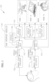
- a closed-loop system 100 for enabling asynchronous control of one or more tasks includes a brain state decoder 101 configured to receive dynamic properties of a user's brain (e.g., blood flow properties and/or electrical emanations that are indicative of neural signals) and to decode these dynamic properties of the user's brain into output control signals to control the one or more task.
- a brain state decoder 101 configured to receive dynamic properties of a user's brain (e.g., blood flow properties and/or electrical emanations that are indicative of neural signals) and to decode these dynamic properties of the user's brain into output control signals to control the one or more task.
- the system 100 also includes a brain state encoder 102 configured to receive status information (e.g., data) from the one or more task and to encode this status information into transcranial stimulation patterns (e.g., brain stimulation montages) which, when transmitted to the user, invoke a brain state that causes a non-sensory cognitive perception of the status of the tasks being performed by the user utilizing the system 100.
- the brain state encoder 102 is configured to supply the status information as non-sensory neural information to the user.
- the one or more tasks may be one or more tasks performed on the same semi-autonomous device or on two or more separate semi-autonomous devices, such as, for instance, air vehicles (e.g., a UAV), ground vehicles, water vehicles, humanoid robots, or interfaces of computers (e.g., desktop or laptop computers).
- air vehicles e.g., a UAV
- ground vehicles e.g., ground vehicles
- water vehicles e.g., humanoid robots
- computers e.g., desktop or laptop computers.
- the brain state decoder 101 and the brain state encoder 102 may have any suitable type or kind of direct neural link to the user.
- the brain state decoder and the brain state encoder may be configured to sense the user's neural signals and transmit neural signals to the user, respectively, either invasively (e.g., from sensors surgically implanted inside the brain) or non-invasively (e.g., by sensors placed outside the user's skull).
- the brain state decoder 101 and the brain state encoder 102 may be any type or kind of decoder and encoder, respectively, suitable for the types of tasks the system 100 is designed to control and depending, for instance, on the desired accuracy and latency of the system 100.
- the brain state decoder 101 may be the brain-machine interface decoder disclosed in U.S. Patent Application No.
- 16/890,406 filed June 02, 2020 , and entitled "System and Method for Continual Decoding of Brain States to Multi-Degree-of-Freedom Control Signals in Hands Free Devices," that is configured to learn a transformation between a specific user's neural data while the user is visualizing the desired control of a task.
- the brain state encoder 102 may be any suitable type or kind of brain state encoder.
- FIG. 5 depicts a brain-state (BS) self-organizing feature map (SOFM).
- the encoding system is personalized based on brain state representations derived from fused sensor signals acquired during testing and training sessions.
- sub-regional activity bounded by Region of Interest coordinates represent brain states. These states are then mapped into a Self-Organizing Feature Map (SOFM), which clusters brain states containing similar features.
- SOFM Self-Organizing Feature Map
- the goal state is a state-node associated with a desired percept identified in the training phase.
- stimulation interventions are represented as action principles between brain state SOFM nodes.
- Each link consists of a representation of the stimulation (e.g., volumetric electric fields) associated with a state-action-state triad.
- the action-principle layer (APL) consists of known (observed) transitions between state-nodes and node-clusters; transitioning from start state to goal state in these cases can be achieved simply by path planning backwards from the goal. If no known paths exist, a radial basis function network (inset, left) is used to learn general rules about directionality within action-link space to bridge the nodes.
- a Self-Organizing Feature Map is a type of artificial neural network that is trained using unsupervised learning to produce a low-dimensional (e.g., two-dimensional), discretized representation of the input space of the training samples, called a map, and is therefore a method to do dimensionality reduction, and clustering.
- the task is to read the brain activity data, cluster it into the most similar cognitive state, and then to provide transcranial stimulation to change that cognitive state into one which causes the user to perceive the sensory feedback.
- the lower layer of the BS-SOFM represents what is called the Action Principles Layer in FIG. 5 .
- the method includes iteratively applying stimulus patterns so as to drive or steer the brain's cognitive state into the desired state.
- a pre-training phase is used to capture information to train the SOFM concerning the application control space as well as consideration of the input signal type and environmental noise that will be present during use (see FIG. 6 ).
- finite element models are derived from structural imaging data ( FIG. 6 , step 1).
- the user will perform a series of tasks in the context of interest with varying cognitive loads.
- multi-modal high-resolution brain activity data is acquired ( FIG. 6 , step 2) to learn the initial predictive relationships between the fused brain data and the control signals in the brain state decoder module ( FIG. 6 , step 3).
- Brain activity data is also acquired while the subject is perceiving or visualizing each of the categories of sensory feedback from the device sensors about the task environment, to be stored as potential goal states in the SOFM lookup table.
- This data is used to identify regions of the brain with the most informative activations as control signals (clustered into nodes in the cognitive states network of the SOFM), and for calculating subject-specific transforms (for the action-principles layer) to align these regions across users ( FIG. 6 , step 4).
- calibration data is obtained by recording brain state dynamics as high-definition transcranial current stimulation (HD-tCS) pulses of varied montages and parameters are applied to initially train the encoder module to be able to rapidly compute a trajectory in HD-tCS space for steering brain activity from an arbitrary start state to a desired goal state ( FIG. 6 , step 5).
- HD-tCS high-definition transcranial current stimulation
- a cap/helmet equipped for recording brain signals is fitted to the user in order to begin training the system algorithms governing the learning of neural patterns for feedback. This allows for learning a personalizable policy of neurostimulation mapped to subjective experience.
- structural models are also developed based on vascular patterns and brain topology for the purpose of generating finite-elements modeling (FEM) predictions of current spread throughout the brain and refining beam-steering properties of electrical stimulation.
- FEM finite-elements modeling
- the user is administered spatio-temporally varying signals targeting, for example, the somatosensory cortex and is asked to report subjective perceptions to map stimulation patterns to behavioral ends.
- the desired behavioral end of the inventive system is being able to convey to the user a certain sensory perception relative to the chosen task/context of interest, solely as a result of changing the user's brain state. That is, the user is unable to perceive the feedback using the 5 senses, but can perceive it due to the stimulation's effect on brain state.
- Also included within this human-in-the-loop testing are subjective measures of discernibility, in order to ensure that mapped sensory stimulation parameters induce sensory information that is clearly distinguishable across 6 or more categories (i.e., 6 or more distinct sensory feedback types). Categories can correspond to different distinct types of status information from the tasks, including any "information", "warning", or "error”.
- Fused blood flow imaging (BOLD) and electrophysiology (EEG) is then computed in order to train the SOFM.
- FEM models are generated and potential montages and protocols are computed using structural imagery of the user's brain.
- a dictionary of possible stimulation combinations and beam-steering properties are encoded and stored.
- the dictionary of neurostimulation intervention definitions are mapped to the neurophysiological/subjective sensory information to enable conversion from sensor percept to subjective sensory experience.
- Action Principles here, stimulation patterns/montages/protocol
- AP Action Principle
- BCI Brain-Computer Interface
- the user's cognitive state is sensed and matched with the states in the Brain State SOFM. Even if there is not a perfect match, the map will return the closest match, which is the current state.
- the sensory feedback state is the goal state, which is found using a lookup table of brain states (created above) that match sensory feedback states for the particular task/context of interest.
- the SOFM's Action-Principles Layer is used to search for a stimulus pattern that can be applied that will take the user's cognitive state closer to the desired state (found above). After each pattern is applied, the brain state is again sensed and the SOFM consulted for the next stimulus pattern to apply. These cycles can take place very rapidly on the order of 10's of milliseconds.
- the goal state is reached (or a state that is clustered with the goal state) the sensory feedback has been delivered to the user.
- FIG. 7 depicts an implementation for sensing a brain state at high temporal and spatial resolution.
- the system or device includes a PhotoAcoustic Tomography (PAT) device or technique and an electroencephalogram (EEG) device or technique.
- PAT and EEG may be combined utilizing a tensor decomposition technique to fuse the multi-dimensional data in a way that employs the advantages of both technique (e.g., the brain state encoder 102 may utilize a method for sensor data fusion employing independent component analysis of tensors).
- PAT is a very high resolution sensing technique that can penetrate the human skull to provide a high-resoluation image with only one-way distoration of ultrasound (compared to round-trip distorations of functional ultrasound), and it is complementary to EEG because of its low speed.
- PAT directly detecs both oxy- and deoxy-hemodynamic changes related to neural activities, and when fused with EEG will preserve high frequency features within high spatiotemporal brain imaging at less than or equal to approximately (about) 1 mm 3 spatial resolution and less than or equal to approximately (about) 10 millisecond (ms) temporal resolution.
- the brain state encoder 102 may learn a self-organizing map that describe parameters for a combined PhotoAcoustic Tomography (PAT)/electroencephalogram (EEG), which will change any brain state into a state in which the user has a non-sensory experience of a particular situational awareness.
- PAT PhotoAcoustic Tomography
- EEG electroencephalogram
- the brain state encoder 102 is a method of producing cognitive states in a user that cause the user to experience a certain sensory perception, without involving the 5 senses.
- the method includes a task of (a) a pre-training phase trains a Brain State Self-Organizing Feature Map (SOFM) to identify the brain regions whose activity correlates with the task and context of interest, and clusters their activity. As the user explored the degrees of freedom of the task/context of interest, each sensory feedback and the brain state it evokes is recorded in a lookup table; (b) an action-principles layer is trained by having the user exercise the degrees of freedom of the task/context of interest.
- SOFM Brain State Self-Organizing Feature Map
- each cognitive state learns how each cognitive state will change when a certain stimulus pattern is applied and translates events in the world into temporal brain stimulation montages to apply non-invasively to a human brain in order to induce a perception of the event; and (c) during operation, each sensory feedback from the monitored system is converted into a goal cognitive state by consulting a lookup table.
- Current brain state is sensed, and a stimulation pattern chosen from the Action Principles Layer that will steer the user's current brain state closer to the goal state. This happens iteratively until the user's cognitive state is clustered with the goal state.
- the system 100 also includes a command multiplexer (MUX) 103 in one or more task interface modules 104 that is configured to receive the output signal from the brain state decoder 101 and configured to output command or control signals to the designated task (e.g., the designated device among two or more devices, or the designated task for a single device among two or more potential tasks for that single device).
- the command MUX 103 may be configured to transmit the commands over any transmission medium suitable for the respective task (e.g., the command MUX 103 may be configured to transmit the commands for the tasks over a wired medium or a wireless medium).
- the system 100 also includes a series of status buffers 105 in the one or more task interface modules 104 that are configured to store status information (e.g., status updates) of the respective tasks.
- the number of status buffers 105 is equal to the number of tasks (e.g., the number of tasks for a single device or the number of different devices) controlled by the system 100, and each status buffer 105 is configured to store the status information (e.g., the status updates) of only a single task.
- the system 100 includes N status buffers 105 corresponding to N number of tasks the system 100 is configured to perform.
- the brain state decoder 101 may be configured to decode the user's neural signals (e.g., as the user visualizes 6 degree of freedom motion from an egocentric perspective, where the degrees of freedom correspond to the 3 components of translation and 3 components of rotation) into a single 6 degree of freedom control command message for the movement task that controls a device (e.g., an aerial vehicle, a robot, a land vehicle, or a maritime vessel), and the task interface module 104 may include a task buffer 105 configured to store this movement command message such that the system 100 is configured to control each of the 6 degrees of freedom of the device. In one or more embodiments, storing the status information in individual status buffers 105 facilitates receiving status information asynchronously from the tasks.
- a device e.g., an aerial vehicle, a robot, a land vehicle, or a maritime vessel
- the task interface module 104 may include a task buffer 105 configured to store this movement command message such that the system 100 is configured to control each of the 6 degrees of freedom of the device.
- the one or more task interface modules 104 includes a status selector module 106 electrically connected to the status buffers 105.
- the status selector module 106 is configured to select which status information (i.e., the status information from which of the status buffers 105) to send to the brain state encoder 102 via a status multiplexer (MUX) 107.
- MUX status multiplexer
- the status selector module 106 is configured with a default task priority for each task, rules for evaluating individual status messages from the tasks, and a timing mechanism to ensure that each task gets to deliver status updates to the user via the brain state encoder at at least a minimum timing frequency, as described in more detail below.
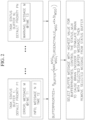
- FIG. 2 is a schematic block diagram illustrating the algorithm programmed on the status selector module 106 according to one embodiment of the present disclosure (e.g., FIG. 2 illustrates pseudo-code for controlling the operation of the status selector module 106 according to one embodiment of the present disclosure).
- the algorithm of the status selector module 106 is configured to select the status information from one of the status buffers 105 that has the highest BufferPriorities value according to the following equation and send that status information to the user via the status MUX 107 and the brain state encoder 102:
- BufferPriorities buffer P buffer ⁇ max msg 1 msg n UrgencyValue msg ⁇ R ⁇ ⁇ t msg
- the algorithm of the status selector module 106 includes a priority parameter, P buffer for each of the tasks (e.g., primary priority for the task of controlling an autonomous aerial vehicle, secondary priority for the task of controlling an interface of a computer monitor, and tertiary priority for the task of controlling a humanoid robot).
- P buffer for each of the tasks (e.g., primary priority for the task of controlling an autonomous aerial vehicle, secondary priority for the task of controlling an interface of a computer monitor, and tertiary priority for the task of controlling a humanoid robot).
- P buffer for each of the tasks (e.g., primary priority for the task of controlling an autonomous aerial vehicle, secondary priority for the task of controlling an interface of a computer monitor, and tertiary priority for the task of controlling a humanoid robot).
- the terms "tasks” and “buffers” are used synonymously or interchangeably because, in one or more embodiments, there is one message buffer representing each task.
- the task priority may be input a-priori by the
- the task priority multiplies the maximum urgency metric, UrgencyValue msg * R * ⁇ t msg , of each task status message (i.e., msg 1 through msg n ) stored in the status buffer 105. Accordingly, the message to be selected for sending is the one with the maximum urgency metric in the buffer with the highest BufferPriority.
- the algorithm of the status selector module 106 multiplies an urgency value, UrgencyValue msg , based on the classification of the status information from the tasks.
- the value assigned to UrgencyValue msg for a particular type of message (msg) may be based on the likelihood of loss or damage if the message is ignored. For example, message types that convey critical failures in the controlled task (e.g., message type ERROR) might be assigned higher UrgencyValue msg than message types that convey benign status updates (e.g., message type INFORMATION or WARNING).
- the urgency value, UrgencyValue msg may be set to one of three different values depending on whether the status information from the task is classified as "information," a "warning," or an "error.” For instance, the urgency value, UrgencyValue msg , may be set to the highest possible value when the status information from the respective task is classified as an error message, the urgency value, UrgencyValue msg , may be set to the lowest possible value when the status information from the respective task is classified as information, and the urgency value, UrgencyValue msg , may be set to an intermediate value when the status information from the respective task is classified as a warning (e.g., an error message may be assigned an urgency value, UrgencyValue msg , of 3, a warning may be assigned an urgency value, UrgencyValue msg , of 2, and information may be assigned an urgency value, UrgencyValue msg , of 1).
- an error message may be assigned an
- the algorithm of the status selector module 106 is configured to ensure that error messages get the highest priority for being transmitted to the user via the status multiplexer 107 and the brain state encoder 102, information gets the lowest priority, and warnings get an intermediate level of priority that is lower than the highest priority assigned to error messages and is higher than the lowest priority assigned to information.
- the algorithm of the status selector module 106 includes three different potential urgency values UrgencyValue msg
- the algorithm of the status selector module 106 may include any other suitable number of different potential urgency values (e.g., more or less than three values) depending on the number of different classifications of the status information from the tasks. Additionally, in one or more embodiments, different values for the urgency value UrgencyValue msg may not increase linearly (e.g., the urgency values may increase exponentially).
- the algorithm for controlling the operation of the status selector module 106 also includes a recency parameter, ⁇ t msg , which denotes the amount of time that has elapsed since the message (msg) containing status information was stored in the status buffer 105. Additionally, in the illustrated embodiment, the algorithm for controlling the operation of the status selector module 106 includes a weighting parameter R configured to weigh the recency parameter, ⁇ t msg (e.g., the weighting parameter R is configured to bias the importance of the recency parameter, ⁇ t msg ). In one or more embodiments, the weighting parameter R may be input a-priori by the user.
- the weighting parameter R may be set to a constant value (e.g., 1) or the weighting parameter R may be a function of the recency parameter, ⁇ t msg .
- the weighting parameter R may be set as a non-linear function (e.g., an exponential function) of the recency parameter, ⁇ t msg , such that the priority of the status information would increase exponentially with the passage of time after the status information was stored in one of the status buffers 105.
- the weighting parameter R may be a hard-coded time limit (e.g., the weighting parameter R may increase or be set to a predetermined value upon the recency parameter ⁇ t msg reaching a preset time limit) or the weighting parameter R may be a function of a task-related variable.
- the weighting parameter R may be a function of the speed of an autonomous vehicle controlled by the system 100 such that the weighting parameter R increases as the speed of the autonomous vehicle (and therefore the frequency at which status information changes) increases.
- the weighting parameter R may be configured to increase the priority of sending the status information to the user via the status MUX 107 and the brain state encoder 102 as the frequency at which the status information from the task changes increases.
- the status selector module 106 is configured to select the status information message with the highest urgency metric from the buffer with the highest value for BufferPriorities (see Equation 1 above) and send this status information to the user via the status MUX 107 and the brain state encoder 102. Additionally, in one or more embodiments, the system 100 is configured to clear the status information stored in the status buffer 105 after that status information is sent to the user via the status MUX 107 and the brain state encoder 102. The algorithm of the status selector module 106 (e.g., the algorithm depicted in FIG. 2 ) is then repeatedly performed to determine the subsequent status information to send to the user via the status MUX 107 and the brain state encoder 102.
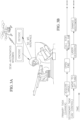
- FIG. 3A is a perspective view of a user (a soldier performing a primary task of controlling a weapon on a mobile platform (i.e., a gunner)) utilizing the embodiment of the system 100 illustrated in FIG. 1 to asynchronously perform two subtasks of a secondary task (UAV control), while the user manually performs the primary task (gunner) unassisted by the system 100.
- the user can perform the primary task of acquiring targets, shooting, and calling for artillery fire all without the aid of the system 100, but the secondary task is controlled by means of the system 100.
- the secondary task might be divided into two subtasks, each subtask with its own message task buffer.
- FIG. 3B is a timeline of the user (the soldier) of FIG. 3A switching between the primary and secondary tasks (gunner and UAV control) utilizing the embodiment of the system 100 illustrated in FIG. 1 . While multitasking, it is well-known that it takes time for the user to reacquire situational awareness when switching tasks.
- Embodiments of the present disclosure make it possible to reduce the acquisition time of the secondary task, because while the user is focused consciously on the primary task, the systems and methods of the present disclosure continue to update status messages from the secondary task, which means they are encoded and applied to the brain, bypassing the senses. Thus, the situational awareness of the secondary task is continually updated subconsiously, even as the user's senses and consciousness are involved with the primary task.
- the brain state decoder 101 of the system 100 is configured to decode the neural signals of the soldier and send the output signal to the command MUX 102, which sends control signals to the secondary task of operating the unmanned aerial vehicle (UAV) (e.g., moving the UAV, laser designating a target, conducting damage assessment, etc.).
- UAV unmanned aerial vehicle
- a first status buffer 105 is configured to receive status information (e.g., status updates such as whether a target has been detected, or damage assessments) ) from the UAV sensing task and a second status buffer 105 is configured to receive status information (e.g., status updates such as arrival at designated waypoint or low fuel indications) from the UAV movement control task.
- status information e.g., status updates such as whether a target has been detected, or damage assessments
- a second status buffer 105 is configured to receive status information (e.g., status updates such as arrival at designated waypoint or low fuel indications) from the UAV movement control task.
- the algorithm of the status selector module 106 e.g., Equation 1 above and depicted in FIG.
- the system 100 is configured to select the status information from one of the status buffers 105 based on a set of parameters, such as, for example, classification of the status information (e.g., an error message, a warning message, or information), the time that has elapsed since each status information message was stored in the status buffer 105, and/or the priority of the tasks to be performed utilizing the system 100.
- the system 100 is configured to then send the selected status information as non-sensory neural data to the user via the status MUX 107 and the brain state encoder 102.
- the system 100 is configured to minimize or at least reduce the time lag (e.g., situation acquisition time) for the operator to switch between one of the gunner tasks and one of the UAV control tasks, as shown in the timeline depicted in FIG. 3B .
- time lag e.g., situation acquisition time
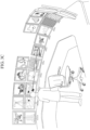
- FIG. 3C is a perspective view of a user (an intelligence analyst) utilizing the embodiment of the system 100 illustrated in FIG. 1 to asynchronously perform tasks of monitoring the content displayed on two or more computer monitors according to one embodiment of the present disclosure (e.g., getting alerts when content on a monitor is urgent, and sending commands from the user to control each task controlling a monitor).
- the brain state decoder 101 of the system 100 is configured to decode the neural signals of the intelligence analyst and send the output signal to the command MUX 102, which sends control signals to the primary task of operating, or analyzing the information displayed on, one of the computer monitors and the secondary task of operating, or analyzing the information displayed on, another one of the computer monitors.
- a first status buffer 105 is configured to receive status information (e.g., status updates such as new information appearing or alerts about particularly critical information) from one of the monitors and a second status buffer 105 is configured to receive status information (e.g., status updates) from another one of the monitors.
- the algorithm of the status selector module 106 e.g., Equation 1 above and depicted in FIG.
- the system 100 is configured to select the status information from one of the status buffers 105 based on a set of parameters, such as, for example, classification of the status information (e.g., an error message, a warning message, or information), the time that has elapsed since the status information was stored in the status buffer 105, and/or the priority of the tasks to be performed utilizing the system 100.
- the system 100 is configured to then send the selected status information as non-sensory neural data to the user via the status MUX 107 and the brain state encoder 102. In this manner, the system 100 is configured to minimize or at least reduce the time lag for the operator to switch between operating and/or analyzing the information displayed on one of the monitors and operating and/or analyzing the information displayed on another one of the monitors.
- system 100 has been described above as being utilized to asynchronously switch between operating and/or analyzing the information displayed on two different monitors, in one or more embodiments, the system 100 of the present disclosure may be utilized to asynchronously switch between operating and/or analyzing the information displayed on three or more different monitors.
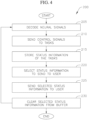
- FIG. 4 is a flowchart illustrating tasks of a method 200 of asynchronous brain control of one or more tasks according to an embodiment of the present disclosure.
- the one or more tasks may be one or more semi-autonomous tasks for controlling or operating a single device (e.g., a single semi-autonomous device) or the two or more tasks may be semi-autonomous tasks for controlling or operating two or more different devices (e.g., two or more different semi-autonomous devices).
- the method 200 may be utilized to perform cognitive control of any semi-autonomous device capable of accepting discrete commands, such as, for instance, air vehicles (e.g., UAVs), ground vehicles, water vehicles, humanoid robots (e.g., a robot arm), or interfaces of computers.
- air vehicles e.g., UAVs
- ground vehicles e.g., water vehicles
- humanoid robots e.g., a robot arm
- interfaces of computers e.g., a robot arm
- the method 200 includes a task 205 of obtaining or receiving dynamic properties of the user's brain (e.g., neural signals, blood flow, and/or electrical emanations) and decoding the neural signals of the user into control signals for controlling the two or more tasks.
- the task 205 of receiving/obtaining the neural signals from the user may be performed either invasively (e.g., by electrodes surgically implanted inside the brain) or non-invasively (e.g., by electrodes placed outside the user's skull).
- the number of control signals decoded from the neural signals of the user in task 205 may be equal to the number of tasks performed utilizing the method 200.
- the task 205 of decoding the user's neural signals may be performed utilizing the decoder 101 described above with reference to the embodiment illustrated in FIG. 1 .
- the control signals may be any suitable type or kind of control signals depending on the type of tasks the system is designed to control, such as, for example, steering commands to an unmanned aerial vehicle or actuation and manipulation control signals to a robot arm.
- the method 200 includes a task 210 of sending the decoded neural signals as control signals to the two or more tasks (e.g., utilizing the command MUX 102 described above with reference to the embodiment illustrated in FIG. 1 ).
- the task 210 of sending the decoded neural signals as control signals to the two or more tasks may be performed by transmitting the control signals over any transmission medium suitable for the respective task (e.g., the control signals may be transmitted over a wired medium or a wireless medium).
- the method 200 also includes a task 215 of storing status information (e.g., status messages) obtained from each of the one or more tasks in individual status buffers (e.g., the status buffers 105 described above with reference to the embodiment illustrated in FIG. 1 ).
- the status information of the tasks may include information (e.g., general information) regarding the status of one of the tasks, a warning regarding one of the tasks, or an indication that an error occurred with one of the tasks.
- the number of status buffers utilized in task 215 to store the status information of the tasks is equal to the number of tasks controlled by the method 200, and each status buffer is configured to store the status information (e.g., the status updates) of only a single task.
- the brain state decoder utilized in task 205 may be configured to decode the user's neural signals into any other suitable number of control signals and the task 215 may include individually storing the status information in any other suitable number of status buffers depending on the number of tasks the method 200 is configured to control. Storing the status information in individual status buffers in task 215 facilitates receiving status information asynchronously from the tasks.
- the method 200 also includes a task 220 of selecting the status information stored in one of the individual status buffers to send to the user.
- the task 220 of selecting the status information to send to the user may be based on a set of parameters, such as, for example, a classification of the status information (e.g., an error message, a warning message, or information), the time that has elapsed since the status information was stored in the status buffer, a weighting factor on the elapsed time since storage in the status buffer, and/or the priority of the tasks to be performed utilizing the method 200.
- a classification of the status information e.g., an error message, a warning message, or information
- the time that has elapsed since the status information was stored in the status buffer e.g., a weighting factor on the elapsed time since storage in the status buffer, and/or the priority of the tasks to be performed utilizing the method 200.
- the task 220 of selecting the status information to send to the user may be performed utilizing the embodiment of the status selector module 106 depicted in FIG. 1 and the status selector module 106 may be programmed with any suitable algorithm for prioritizing the status information, such as, for example, Equation 1 described above with reference to embodiment depicted in FIG. 2 .
- the method 200 also includes a task 225 of sending the status information that was selected in task 220 to the user as brain stimulation montages that create a non-sensory awareness in the user of the status information (e.g., non-sensory awareness of the task state of one of the two or more tasks). That is, in one or more embodiments, the task 225 includes transmitting the selected status information of one of the tasks to the user as non-sensory neural data (e.g., the selected status information bypasses the user's senses and is transmitted directly to the user's short-term memory).
- the task 225 of sending the selected status information to the user may be performed utilizing the embodiment of the status MUX 107 and the embodiment of the brain state encoder 102 described above with reference to the embodiment depicted in FIG. 1 . Additionally, in one or more embodiments, the task 225 of sending the status information to the user as non-sensory neural data may be performed either invasively (e.g., by electrodes surgically implanted inside the brain) or non-invasively (e.g., by electrodes placed outside the user's skull).
- Sending the selected status information to the user as non-sensory neural data in task 225 reduces the amount of time it takes for the user to reacquire cognitive situational awareness of the task about which the status information was provided when switching from performing another task. Reducing the amount of time it takes the user to reacquire cognitive situational awareness enables the user to rapidly switch between performing the two or more tasks.
- task 225 which keeps the user informed of the status of a second task via non-sensory neural data while performing a first task, minimizes or at least reduces the lag time in the user reacquiring situational awareness of the second task, which enables the user to regain effective, informed control of the second task after switching away from performing the first task.
- the method 200 enables asynchronous control of the two or more tasks with low-latency, such as latency less than or equal to approximately 50 ms.
- the method 200 includes a task 230 of clearing the selected status information from the status buffer in which that status information was stored.
- the task 205 of decoding the user's neural signals, the task 210 of sending the decoded neural signals as control signals for performing two or more tasks, the task 215 of storing status information about the two or more tasks, the task 220 of selecting status information to send to the user, the task 225 of sending the selected information to the user as non-sensory neural data, and the task 230 of clearing the selected status information from the status buffer are repeatedly performed until the operation of controlling the two or more tasks has completed.
- the method 200 of the present disclosure is configured to enable continuous, asynchronous cognitive control of the two or more tasks with low-latency for a sustained duration, such as, for example, up to approximately (about) two (2) hours or more, depending on how long the encoding/decoding device can be safely interfaced to the brain of the user, and the user's fatigue level.
- any suitable hardware, firmware e.g. an application-specific integrated circuit
- software e.g. an application-specific integrated circuit
- the various components of the system may be formed on one integrated circuit (IC) chip or on separate IC chips.
- the various components of the system may be implemented on a flexible printed circuit film, a tape carrier package (TCP), a printed circuit board (PCB), or formed on one substrate.
- the various components of the system may be a process or thread, running on one or more processors, in one or more computing devices, executing computer program instructions and interacting with other system components for performing the various functionalities described herein.
- the computer program instructions are stored in a memory which may be implemented in a computing device using a standard memory device, such as, for example, a random access memory (RAM).
- the computer program instructions may also be stored in other non-transitory computer readable media such as, for example, a CD-ROM, flash drive, or the like.
- a person of skill in the art should recognize that the functionality of various computing devices may be combined or integrated into a single computing device, or the functionality of a particular computing device may be distributed across one or more other computing devices without departing from the scope of the exemplary embodiments of the present invention.
Landscapes
- Engineering & Computer Science (AREA)
- Health & Medical Sciences (AREA)
- Theoretical Computer Science (AREA)
- Physics & Mathematics (AREA)
- General Engineering & Computer Science (AREA)
- Life Sciences & Earth Sciences (AREA)
- Software Systems (AREA)
- General Physics & Mathematics (AREA)
- Biomedical Technology (AREA)
- General Health & Medical Sciences (AREA)
- Molecular Biology (AREA)
- Veterinary Medicine (AREA)
- Heart & Thoracic Surgery (AREA)
- Medical Informatics (AREA)
- Biophysics (AREA)
- Surgery (AREA)
- Animal Behavior & Ethology (AREA)
- Human Computer Interaction (AREA)
- Public Health (AREA)
- Pathology (AREA)
- Neurosurgery (AREA)
- Neurology (AREA)
- Dermatology (AREA)
- Psychology (AREA)
- Psychiatry (AREA)
- Acoustics & Sound (AREA)
- User Interface Of Digital Computer (AREA)
- Measurement And Recording Of Electrical Phenomena And Electrical Characteristics Of The Living Body (AREA)
Claims (14)
- Geschlossenes Regelsystem (100) zur asynchronen Gehirnsteuerung mindestens einer Aufgabe, wobei das System Folgendes umfasst:einen Gehirnzustandsdecodierer (101), der dazu ausgestaltet ist, Nervensignale eines Benutzers in Steuersignale zur Steuerung der mindestens einen Aufgabe zu decodieren;ein Aufgabenschnittstellenmodul (104), das dazu ausgestaltet ist, die Steuersignale an die mindestens eine Aufgabe zu übertragen, in mindestens einem Statuszwischenspeicher (105) Statusinformationen, die eine Mehrzahl von Nachrichten bezüglich jeder der mindestens einen Aufgabe umfassen, zu speichern und eine Nachricht der Mehrzahl von Nachrichten zur Übertragung an den Benutzer auszuwählen; undeinen Gehirnzustandscodierer (102), der dazu ausgestaltet ist, die eine von dem Aufgabenschnittstellenmodul empfangene Nachricht in Gehirnzustandsmontagen abzubilden und unter Verwendung von Elektroden die Gehirnzustandsmontagen an das Kurzzeitgedächtnis des Benutzers zu übertragen,wobei die Gehirnzustandsmontagen Statusinformationen als transkranielle Stimulationsmuster codieren und dazu ausgestaltet sind, eine nichtsensorische kognitive Wahrnehmung in dem Benutzer der Statusinformationen bezüglich der mindestens einen Aufgabe zu erzeugen, wenn sie übertragen werden.
- System nach Anspruch 1, wobei das Aufgabenschnittstellenmodul Folgendes umfasst:mindestens einen Statuszwischenspeicher, der dazu ausgestaltet ist, die Statusinformationen der mindestens einen Aufgabe zu speichern; undein Statusselektormodul (106), programmiert mit einem Algorithmus, der dazu ausgestaltet ist, die eine Nachricht aus der Mehrzahl von Nachrichten bezüglich der mindestens einen Aufgabe auf der Grundlage einer Klassifizierung der Statusinformationen, eines Aktualitätsparameters und einer Priorität der mindestens einen Aufgabe auszuwählen.
- System nach Anspruch 2, wobei der Algorithmus ferner einen Gewichtungsparameter umfasst, der den Aktualitätsparameter gewichtet, und wobei der Gewichtungsparameter ein konstanter Wert oder eine Funktion des Aktualitätsparameters ist.
- System nach Anspruch 3, wobei der Gewichtungsparameter die Funktion des Aktualitätsparameters ist und wobei die Funktion eine nichtlineare Funktion ist.
- System nach einem der Ansprüche 2, 3 oder 4, wobei der Algorithmus wie folgt ist:
 wobei msg 1 bis msgn die Mehrzahl von Nachrichten bezüglich der mindestens einen Aufgabe sind, Pbuffer ein Apriori-Wert ist, der eine Priorität jedes des mindestens einen Statuszwischenspeichers darstellt, UrgencyValuemsg ein Dringlichkeitswert auf der Grundlage einer Klassifizierung jeder der Mehrzahl von Nachrichten ist,Δtmsg ein Aktualitätsparameter ist, der eine Aktualität der Mehrzahl von Nachrichten widerspiegelt, und R ein Gewichtungsparameter ist, der eine Wichtigkeit des Aktualitätsparameters widerspiegelt, undwobei die eine durch das Statusselektormodul ausgewählte Nachricht eine Nachricht der Mehrzahl von Nachrichten mit einem höchsten BufferPriorities -Wert ist.
 - System nach einem der Ansprüche 2, 3, 4 oder 5, wobei das Aufgabenschnittstellenmodul ferner einen Befehlsmultiplexer (103) umfasst, der dazu ausgestaltet ist, die Steuersignale an die mindestens eine Aufgabe zu übertragen.
- System nach einem der Ansprüche 2, 3, 4, 5 oder 6, wobei das Aufgabenschnittstellenmodul ferner einen Statusmultiplexer (107) umfasst, der dazu ausgestaltet ist, die Statusinformationen der einen der mindestens einen Aufgabe an den Gehirnzustandscodierer zu übertragen.
- System nach einem der Ansprüche 1, 2, 3, 4, 5, 6 oder 7, wobei die mindestens eine Aufgabe auf einer selben halbautonomen Vorrichtung oder auf zwei oder mehr getrennten halbautonomen Vorrichtungen ausgeführt wird.
- Verfahren zur asynchronen Steuerung mindestens einer Aufgabe in einem geschlossenen Regelsystem, wobei das Verfahren Folgendes umfasst:Decodieren, mit einem Gehirnzustandsdecodierer, von Nervensignalen eines Benutzers in ein Befehlssignal;Übertragen des Befehlssignales an die mindestens eine Aufgabe;Speichern, in mindestens einem Statuszwischenspeicher, von Statusinformationen, die eine Mehrzahl von Nachrichten bezüglich jeder der mindestens einen Aufgabe umfassen;Auswählen, mit einem Statusselektormodul, das mit einem Algorithmus programmiert ist, einer Nachricht der Mehrzahl von Nachrichten;Codieren, mit einem Gehirnzustandscodierer, der einen Nachricht in Gehirnzustandsmontagen zur Übertragung an den Benutzer; undÜbertragen, unter Verwendung von Elektroden, der Gehirnzustandsmontagen direkt an das Kurzzeitgedächtnis des Benutzers, wobei die Gehirnzustandsmontagen Statusinformationen als transkranielle Stimulationsmuster codieren und dazu ausgestaltet sind, eine nichtsensorische kognitive Wahrnehmung in dem Benutzer der Statusinformationen bezüglich der mindestens einen Aufgabe zu erzeugen, wenn sie übertragen werden.
- Verfahren nach Anspruch 9, ferner umfassend das invasive oder nichtinvasive Erlangen der Nervensignale von dem Benutzer.
- Verfahren nach einem der Ansprüche 9-10, wobei der Algorithmus eine Klassifizierung der Mehrzahl von Nachrichten, einen Aktualitätsparameter und eine Priorität der Mehrzahl von Nachrichten umfasst.
- Verfahren nach Anspruch 11, wobei der Algorithmus ferner einen Gewichtungsparameter umfasst, der den Aktualitätsparameter gewichtet, und wobei der Gewichtungsparameter ein konstanter Wert oder eine Funktion des Aktualitätsparameters ist.
- Verfahren nach Anspruch 12, wobei der Gewichtungsparameter die Funktion des Aktualitätsparameters ist und wobei die Funktion eine nichtlineare Funktion ist.
- Verfahren nach einem der Ansprüche 9-13, wobei der Algorithmus wie folgt ist:
 wobei msg 1 bis msgn die Mehrzahl von Nachrichten bezüglich der mindestens einen Aufgabe sind, Pbuffer ein Apriori-Wert ist, der eine Priorität jedes des mindestens einen Statuszwischenspeichers darstellt, UrgencyValuemsg ein Dringlichkeitswert auf der Grundlage einer Klassifizierung jeder der Mehrzahl von Nachrichten ist,Δtmsg ein Aktualitätsparameter ist, der eine Aktualität der Mehrzahl von Nachrichten widerspiegelt, und R ein Gewichtungsparameter ist, der eine Wichtigkeit des Aktualitätsparameters widerspiegelt, undwobei die eine durch das Statusselektormodul ausgewählte Nachricht eine Nachricht der Mehrzahl von Nachrichten mit einem höchsten BufferPriorities -Wert ist.
Applications Claiming Priority (2)
| Application Number | Priority Date | Filing Date | Title |
|---|---|---|---|
| US202062970079P | 2020-02-04 | 2020-02-04 | |
| PCT/US2020/063274 WO2021158276A1 (en) | 2020-02-04 | 2020-12-04 | System and method for asynchronous brain control of one or more tasks |
Publications (3)
| Publication Number | Publication Date |
|---|---|
| EP4100816A1 EP4100816A1 (de) | 2022-12-14 |
| EP4100816A4 EP4100816A4 (de) | 2023-07-05 |
| EP4100816B1 true EP4100816B1 (de) | 2024-07-31 |
Family
ID=77200260
Family Applications (1)
| Application Number | Title | Priority Date | Filing Date |
|---|---|---|---|
| EP20917523.1A Active EP4100816B1 (de) | 2020-02-04 | 2020-12-04 | System und verfahren zur asynchronen gehirnsteuerung von einer oder mehreren aufgaben |
Country Status (4)
| Country | Link |
|---|---|
| US (1) | US11237634B2 (de) |
| EP (1) | EP4100816B1 (de) |
| CN (1) | CN114981755B (de) |
| WO (1) | WO2021158276A1 (de) |
Families Citing this family (7)
| Publication number | Priority date | Publication date | Assignee | Title |
|---|---|---|---|---|
| FR3118413B1 (fr) * | 2020-12-29 | 2024-05-10 | Commissariat Energie Atomique | Méthode d’apprentissage auto-adaptatif d’une interface neuronale directe utilisant une détection physique d’état mental |
| CN112735570B (zh) * | 2021-01-09 | 2022-02-22 | 深圳先进技术研究院 | 影像驱动的脑图谱构建方法、装置、设备及存储介质 |
| EP4287947A4 (de) * | 2021-02-03 | 2025-01-15 | Synchron Australia Pty Ltd | Neuromonitoring-diagnosesysteme |
| CN114035679B (zh) * | 2021-10-26 | 2023-11-17 | 浙江大学 | 一种可动态重组的脑神经信号并行解码方法和装置 |
| US20240069501A1 (en) * | 2022-08-30 | 2024-02-29 | Mitsubishi Electric Research Laboratories, Inc. | System and Method for Controlling an Entity |
| CN117573329B (zh) * | 2024-01-16 | 2024-05-03 | 深圳市极限网络科技有限公司 | 多脑协同的任务调度方法、任务调度装置及存储介质 |
| CN120672163A (zh) * | 2025-06-09 | 2025-09-19 | 昆山梦宇三维数字技术有限公司 | 面向城市改建全生命周期的智能调度与协同系统及其方法 |
Family Cites Families (13)
| Publication number | Priority date | Publication date | Assignee | Title |
|---|---|---|---|---|
| JP3993069B2 (ja) * | 2002-10-30 | 2007-10-17 | 三菱電機株式会社 | 脳波信号を利用した制御装置 |
| US8005766B2 (en) * | 2007-03-23 | 2011-08-23 | Nokia Corporation | Apparatus, method and computer program product providing a hierarchical approach to command-control tasks using a brain-computer interface |
| WO2008137346A2 (en) | 2007-05-02 | 2008-11-13 | University Of Florida Research Foundation, Inc. | System and method for brain machine interface (bmi) control using reinforcement learning |
| US9081742B2 (en) * | 2009-04-27 | 2015-07-14 | Intel Corporation | Network communications processor architecture |
| TW201238562A (en) * | 2011-03-25 | 2012-10-01 | Univ Southern Taiwan | Brain wave control system and method |
| EP2768385B1 (de) * | 2011-10-21 | 2021-03-31 | Cerevast Medical, Inc. | System zur direkten kommunikation |
| EP2972662A4 (de) * | 2013-03-15 | 2017-03-01 | Intel Corporation | Gehirn-computer-schnittstellensystem auf basis der erfassung zeitlicher und räumlicher muster biophysikalischer signale |
| US9539118B2 (en) * | 2013-03-15 | 2017-01-10 | Neurolutions, Inc. | Brain-controlled body movement assistance devices and methods |
| US10241575B2 (en) * | 2013-10-31 | 2019-03-26 | Commissariat A L'energie Atomique Et Aux Energies Alternatives | Direct neural interface system and method |
| US10695574B2 (en) * | 2015-10-21 | 2020-06-30 | University Of Washington | Sensory input through non-invasive brain stimulation |
| WO2019144025A1 (en) * | 2018-01-22 | 2019-07-25 | Hrl Laboratories, Llc | Neuro-adaptive body sensing for user states framework (nabsus) |
| CN109062398B (zh) * | 2018-06-07 | 2021-06-29 | 中国航天员科研训练中心 | 一种基于虚拟现实与多模态人机接口的航天器交会对接方法 |
| WO2019239367A1 (en) | 2018-06-14 | 2019-12-19 | Inner Cosmos Llc | Virtual user interface system and methods for use thereof |
-
2020
- 2020-12-04 EP EP20917523.1A patent/EP4100816B1/de active Active
- 2020-12-04 WO PCT/US2020/063274 patent/WO2021158276A1/en not_active Ceased
- 2020-12-04 CN CN202080090173.0A patent/CN114981755B/zh active Active
- 2020-12-04 US US17/112,052 patent/US11237634B2/en active Active
Also Published As
| Publication number | Publication date |
|---|---|
| CN114981755B (zh) | 2025-11-25 |
| EP4100816A4 (de) | 2023-07-05 |
| US11237634B2 (en) | 2022-02-01 |
| WO2021158276A1 (en) | 2021-08-12 |
| EP4100816A1 (de) | 2022-12-14 |
| US20210240265A1 (en) | 2021-08-05 |
| CN114981755A (zh) | 2022-08-30 |
Similar Documents
| Publication | Publication Date | Title |
|---|---|---|
| EP4100816B1 (de) | System und verfahren zur asynchronen gehirnsteuerung von einer oder mehreren aufgaben | |
| Escolano et al. | A telepresence mobile robot controlled with a noninvasive brain–computer interface | |
| JP7014129B2 (ja) | 推定器生成装置、モニタリング装置、推定器生成方法及び推定器生成プログラム | |
| EP3459807A1 (de) | System zur überwachung eines bedieners | |
| US20240400083A1 (en) | Method and System for Collaborative Task-Based Allocation Between Human and Autonomous Systems | |
| Ajmeria et al. | A critical survey of EEG-based BCI systems for applications in industrial internet of things | |
| CN113778113B (zh) | 一种基于多模态生理信号的飞行员辅助驾驶方法及系统 | |
| Li et al. | Noninvasive EEG-based intelligent mobile robots: a systematic review | |
| Dalilian et al. | Biometrically measured affect for screen-based drone pilot skill acquisition | |
| EP3944049B1 (de) | Betrieb eines mobilen kommunikationsendgerätes eines roboterendgerätes | |
| Cassenti et al. | Using cognitive modeling for adaptive automation triggering | |
| Bazzano et al. | Mental workload assessment for UAV Traffic control using consumer-grade BCI equipment | |
| Goh et al. | Construction of air traffic controller’s decision network using error-related potential | |
| Ciabattoni et al. | Human-in-the-loop approach to safe navigation of a smart wheelchair via brain computer interface | |
| Pietracupa et al. | Detection of Pre-error States in Aircraft Pilots Through Machine Learning | |
| Forsythe et al. | Augmented cognition | |
| US12505361B2 (en) | System and method for predicting manned unmanned teaming (MUM-T) autonomy overrides | |
| Distefano | Augmenting Artificial Intelligence Design and Performance With Human Physiological and Behavioral Information | |
| Wang et al. | Design and Application of Digital Twin‐Based Brain Control System | |
| Jayarajah et al. | TagTeam: Towards wearable-assisted, implicit guidance for human-drone teams | |
| Kowalska | Brain–computer interface for autonomous vehicles: An investigation of a hands-free control system | |
| Zhang et al. | Enhancing Gesture-Based Human-Drone Interaction in Emergency Scenarios: An Elicitation Study | |
| Periyanan et al. | Next-Generation Adaptive Wearable Devices for Dual-Mode Therapy: Integration of Bioinformatics and Real-Time Computational Intelligence | |
| Jiang et al. | Understanding Trust and Fatigue Under Transparency Regulation in Air Traffic Control: A Multimodal Approach | |
| Simonetto et al. | Enhancing Motor Imagery Decoding with Environmental Context During Robot Control |
Legal Events
| Date | Code | Title | Description |
|---|---|---|---|
| STAA | Information on the status of an ep patent application or granted ep patent |
Free format text: STATUS: THE INTERNATIONAL PUBLICATION HAS BEEN MADE |
|
| PUAI | Public reference made under article 153(3) epc to a published international application that has entered the european phase |
Free format text: ORIGINAL CODE: 0009012 |
|
| STAA | Information on the status of an ep patent application or granted ep patent |
Free format text: STATUS: REQUEST FOR EXAMINATION WAS MADE |
|
| 17P | Request for examination filed |
Effective date: 20220516 |
|
| AK | Designated contracting states |
Kind code of ref document: A1 Designated state(s): AL AT BE BG CH CY CZ DE DK EE ES FI FR GB GR HR HU IE IS IT LI LT LU LV MC MK MT NL NO PL PT RO RS SE SI SK SM TR |
|
| DAV | Request for validation of the european patent (deleted) | ||
| DAX | Request for extension of the european patent (deleted) | ||
| A4 | Supplementary search report drawn up and despatched |
Effective date: 20230601 |
|
| RIC1 | Information provided on ipc code assigned before grant |
Ipc: A61B 5/374 20210101ALI20230526BHEP Ipc: A61B 5/291 20210101ALI20230526BHEP Ipc: A61B 5/378 20210101ALI20230526BHEP Ipc: G06F 3/01 20060101AFI20230526BHEP |
|
| GRAP | Despatch of communication of intention to grant a patent |
Free format text: ORIGINAL CODE: EPIDOSNIGR1 |
|
| STAA | Information on the status of an ep patent application or granted ep patent |
Free format text: STATUS: GRANT OF PATENT IS INTENDED |
|
| RIC1 | Information provided on ipc code assigned before grant |
Ipc: A61B 5/372 20210101ALI20240318BHEP Ipc: A61B 5/00 20060101ALI20240318BHEP Ipc: A61B 5/374 20210101ALI20240318BHEP Ipc: A61B 5/291 20210101ALI20240318BHEP Ipc: A61B 5/378 20210101ALI20240318BHEP Ipc: G06F 3/01 20060101AFI20240318BHEP |
|
| INTG | Intention to grant announced |
Effective date: 20240405 |
|
| GRAS | Grant fee paid |
Free format text: ORIGINAL CODE: EPIDOSNIGR3 |
|
| GRAA | (expected) grant |
Free format text: ORIGINAL CODE: 0009210 |
|
| STAA | Information on the status of an ep patent application or granted ep patent |
Free format text: STATUS: THE PATENT HAS BEEN GRANTED |
|
| AK | Designated contracting states |
Kind code of ref document: B1 Designated state(s): AL AT BE BG CH CY CZ DE DK EE ES FI FR GB GR HR HU IE IS IT LI LT LU LV MC MK MT NL NO PL PT RO RS SE SI SK SM TR |
|
| REG | Reference to a national code |
Ref country code: CH Ref legal event code: EP Ref country code: GB Ref legal event code: FG4D |
|
| REG | Reference to a national code |
Ref country code: DE Ref legal event code: R096 Ref document number: 602020035092 Country of ref document: DE |
|
| REG | Reference to a national code |
Ref country code: IE Ref legal event code: FG4D |
|
| P01 | Opt-out of the competence of the unified patent court (upc) registered |
Free format text: CASE NUMBER: APP_49319/2024 Effective date: 20240830 |
|
| REG | Reference to a national code |
Ref country code: LT Ref legal event code: MG9D |
|
| REG | Reference to a national code |
Ref country code: NL Ref legal event code: MP Effective date: 20240731 |
|
| PG25 | Lapsed in a contracting state [announced via postgrant information from national office to epo] |
Ref country code: PT Free format text: LAPSE BECAUSE OF FAILURE TO SUBMIT A TRANSLATION OF THE DESCRIPTION OR TO PAY THE FEE WITHIN THE PRESCRIBED TIME-LIMIT Effective date: 20241202 |
|
| REG | Reference to a national code |
Ref country code: AT Ref legal event code: MK05 Ref document number: 1709086 Country of ref document: AT Kind code of ref document: T Effective date: 20240731 |
|
| PG25 | Lapsed in a contracting state [announced via postgrant information from national office to epo] |
Ref country code: PT Free format text: LAPSE BECAUSE OF FAILURE TO SUBMIT A TRANSLATION OF THE DESCRIPTION OR TO PAY THE FEE WITHIN THE PRESCRIBED TIME-LIMIT Effective date: 20241202 |
|
| PG25 | Lapsed in a contracting state [announced via postgrant information from national office to epo] |
Ref country code: NO Free format text: LAPSE BECAUSE OF FAILURE TO SUBMIT A TRANSLATION OF THE DESCRIPTION OR TO PAY THE FEE WITHIN THE PRESCRIBED TIME-LIMIT Effective date: 20241031 |
|
| PG25 | Lapsed in a contracting state [announced via postgrant information from national office to epo] |
Ref country code: GR Free format text: LAPSE BECAUSE OF FAILURE TO SUBMIT A TRANSLATION OF THE DESCRIPTION OR TO PAY THE FEE WITHIN THE PRESCRIBED TIME-LIMIT Effective date: 20241101 Ref country code: FI Free format text: LAPSE BECAUSE OF FAILURE TO SUBMIT A TRANSLATION OF THE DESCRIPTION OR TO PAY THE FEE WITHIN THE PRESCRIBED TIME-LIMIT Effective date: 20240731 Ref country code: NL Free format text: LAPSE BECAUSE OF FAILURE TO SUBMIT A TRANSLATION OF THE DESCRIPTION OR TO PAY THE FEE WITHIN THE PRESCRIBED TIME-LIMIT Effective date: 20240731 Ref country code: PL Free format text: LAPSE BECAUSE OF FAILURE TO SUBMIT A TRANSLATION OF THE DESCRIPTION OR TO PAY THE FEE WITHIN THE PRESCRIBED TIME-LIMIT Effective date: 20240731 |
|
| PG25 | Lapsed in a contracting state [announced via postgrant information from national office to epo] |
Ref country code: BG Free format text: LAPSE BECAUSE OF FAILURE TO SUBMIT A TRANSLATION OF THE DESCRIPTION OR TO PAY THE FEE WITHIN THE PRESCRIBED TIME-LIMIT Effective date: 20240731 |
|
| PG25 | Lapsed in a contracting state [announced via postgrant information from national office to epo] |
Ref country code: LV Free format text: LAPSE BECAUSE OF FAILURE TO SUBMIT A TRANSLATION OF THE DESCRIPTION OR TO PAY THE FEE WITHIN THE PRESCRIBED TIME-LIMIT Effective date: 20240731 |
|
| PG25 | Lapsed in a contracting state [announced via postgrant information from national office to epo] |
Ref country code: AT Free format text: LAPSE BECAUSE OF FAILURE TO SUBMIT A TRANSLATION OF THE DESCRIPTION OR TO PAY THE FEE WITHIN THE PRESCRIBED TIME-LIMIT Effective date: 20240731 Ref country code: IS Free format text: LAPSE BECAUSE OF FAILURE TO SUBMIT A TRANSLATION OF THE DESCRIPTION OR TO PAY THE FEE WITHIN THE PRESCRIBED TIME-LIMIT Effective date: 20241130 |
|
| PG25 | Lapsed in a contracting state [announced via postgrant information from national office to epo] |
Ref country code: HR Free format text: LAPSE BECAUSE OF FAILURE TO SUBMIT A TRANSLATION OF THE DESCRIPTION OR TO PAY THE FEE WITHIN THE PRESCRIBED TIME-LIMIT Effective date: 20240731 |
|
| PG25 | Lapsed in a contracting state [announced via postgrant information from national office to epo] |
Ref country code: RS Free format text: LAPSE BECAUSE OF FAILURE TO SUBMIT A TRANSLATION OF THE DESCRIPTION OR TO PAY THE FEE WITHIN THE PRESCRIBED TIME-LIMIT Effective date: 20241031 Ref country code: ES Free format text: LAPSE BECAUSE OF FAILURE TO SUBMIT A TRANSLATION OF THE DESCRIPTION OR TO PAY THE FEE WITHIN THE PRESCRIBED TIME-LIMIT Effective date: 20240731 |
|
| PG25 | Lapsed in a contracting state [announced via postgrant information from national office to epo] |
Ref country code: RS Free format text: LAPSE BECAUSE OF FAILURE TO SUBMIT A TRANSLATION OF THE DESCRIPTION OR TO PAY THE FEE WITHIN THE PRESCRIBED TIME-LIMIT Effective date: 20241031 Ref country code: PL Free format text: LAPSE BECAUSE OF FAILURE TO SUBMIT A TRANSLATION OF THE DESCRIPTION OR TO PAY THE FEE WITHIN THE PRESCRIBED TIME-LIMIT Effective date: 20240731 Ref country code: NO Free format text: LAPSE BECAUSE OF FAILURE TO SUBMIT A TRANSLATION OF THE DESCRIPTION OR TO PAY THE FEE WITHIN THE PRESCRIBED TIME-LIMIT Effective date: 20241031 Ref country code: NL Free format text: LAPSE BECAUSE OF FAILURE TO SUBMIT A TRANSLATION OF THE DESCRIPTION OR TO PAY THE FEE WITHIN THE PRESCRIBED TIME-LIMIT Effective date: 20240731 Ref country code: LV Free format text: LAPSE BECAUSE OF FAILURE TO SUBMIT A TRANSLATION OF THE DESCRIPTION OR TO PAY THE FEE WITHIN THE PRESCRIBED TIME-LIMIT Effective date: 20240731 Ref country code: IS Free format text: LAPSE BECAUSE OF FAILURE TO SUBMIT A TRANSLATION OF THE DESCRIPTION OR TO PAY THE FEE WITHIN THE PRESCRIBED TIME-LIMIT Effective date: 20241130 Ref country code: HR Free format text: LAPSE BECAUSE OF FAILURE TO SUBMIT A TRANSLATION OF THE DESCRIPTION OR TO PAY THE FEE WITHIN THE PRESCRIBED TIME-LIMIT Effective date: 20240731 Ref country code: GR Free format text: LAPSE BECAUSE OF FAILURE TO SUBMIT A TRANSLATION OF THE DESCRIPTION OR TO PAY THE FEE WITHIN THE PRESCRIBED TIME-LIMIT Effective date: 20241101 Ref country code: FI Free format text: LAPSE BECAUSE OF FAILURE TO SUBMIT A TRANSLATION OF THE DESCRIPTION OR TO PAY THE FEE WITHIN THE PRESCRIBED TIME-LIMIT Effective date: 20240731 Ref country code: ES Free format text: LAPSE BECAUSE OF FAILURE TO SUBMIT A TRANSLATION OF THE DESCRIPTION OR TO PAY THE FEE WITHIN THE PRESCRIBED TIME-LIMIT Effective date: 20240731 Ref country code: BG Free format text: LAPSE BECAUSE OF FAILURE TO SUBMIT A TRANSLATION OF THE DESCRIPTION OR TO PAY THE FEE WITHIN THE PRESCRIBED TIME-LIMIT Effective date: 20240731 Ref country code: AT Free format text: LAPSE BECAUSE OF FAILURE TO SUBMIT A TRANSLATION OF THE DESCRIPTION OR TO PAY THE FEE WITHIN THE PRESCRIBED TIME-LIMIT Effective date: 20240731 |
|
| PG25 | Lapsed in a contracting state [announced via postgrant information from national office to epo] |
Ref country code: DK Free format text: LAPSE BECAUSE OF FAILURE TO SUBMIT A TRANSLATION OF THE DESCRIPTION OR TO PAY THE FEE WITHIN THE PRESCRIBED TIME-LIMIT Effective date: 20240731 Ref country code: RO Free format text: LAPSE BECAUSE OF FAILURE TO SUBMIT A TRANSLATION OF THE DESCRIPTION OR TO PAY THE FEE WITHIN THE PRESCRIBED TIME-LIMIT Effective date: 20240731 Ref country code: SM Free format text: LAPSE BECAUSE OF FAILURE TO SUBMIT A TRANSLATION OF THE DESCRIPTION OR TO PAY THE FEE WITHIN THE PRESCRIBED TIME-LIMIT Effective date: 20240731 |
|
| PG25 | Lapsed in a contracting state [announced via postgrant information from national office to epo] |
Ref country code: EE Free format text: LAPSE BECAUSE OF FAILURE TO SUBMIT A TRANSLATION OF THE DESCRIPTION OR TO PAY THE FEE WITHIN THE PRESCRIBED TIME-LIMIT Effective date: 20240731 |
|
| PG25 | Lapsed in a contracting state [announced via postgrant information from national office to epo] |
Ref country code: CZ Free format text: LAPSE BECAUSE OF FAILURE TO SUBMIT A TRANSLATION OF THE DESCRIPTION OR TO PAY THE FEE WITHIN THE PRESCRIBED TIME-LIMIT Effective date: 20240731 |
|
| PG25 | Lapsed in a contracting state [announced via postgrant information from national office to epo] |
Ref country code: SK Free format text: LAPSE BECAUSE OF FAILURE TO SUBMIT A TRANSLATION OF THE DESCRIPTION OR TO PAY THE FEE WITHIN THE PRESCRIBED TIME-LIMIT Effective date: 20240731 Ref country code: IT Free format text: LAPSE BECAUSE OF FAILURE TO SUBMIT A TRANSLATION OF THE DESCRIPTION OR TO PAY THE FEE WITHIN THE PRESCRIBED TIME-LIMIT Effective date: 20240731 |
|
| REG | Reference to a national code |
Ref country code: DE Ref legal event code: R097 Ref document number: 602020035092 Country of ref document: DE |
|
| PLBE | No opposition filed within time limit |
Free format text: ORIGINAL CODE: 0009261 |
|
| STAA | Information on the status of an ep patent application or granted ep patent |
Free format text: STATUS: NO OPPOSITION FILED WITHIN TIME LIMIT |
|
| PG25 | Lapsed in a contracting state [announced via postgrant information from national office to epo] |
Ref country code: MC Free format text: LAPSE BECAUSE OF FAILURE TO SUBMIT A TRANSLATION OF THE DESCRIPTION OR TO PAY THE FEE WITHIN THE PRESCRIBED TIME-LIMIT Effective date: 20240731 |
|
| 26N | No opposition filed |
Effective date: 20250501 |
|
| REG | Reference to a national code |
Ref country code: CH Ref legal event code: PL |
|
| PG25 | Lapsed in a contracting state [announced via postgrant information from national office to epo] |
Ref country code: LU Free format text: LAPSE BECAUSE OF NON-PAYMENT OF DUE FEES Effective date: 20241204 |
|
| GBPC | Gb: european patent ceased through non-payment of renewal fee |
Effective date: 20241204 |
|
| PG25 | Lapsed in a contracting state [announced via postgrant information from national office to epo] |
Ref country code: SE Free format text: LAPSE BECAUSE OF FAILURE TO SUBMIT A TRANSLATION OF THE DESCRIPTION OR TO PAY THE FEE WITHIN THE PRESCRIBED TIME-LIMIT Effective date: 20240731 |
|
| REG | Reference to a national code |
Ref country code: BE Ref legal event code: MM Effective date: 20241231 |
|
| PG25 | Lapsed in a contracting state [announced via postgrant information from national office to epo] |
Ref country code: GB Free format text: LAPSE BECAUSE OF NON-PAYMENT OF DUE FEES Effective date: 20241204 Ref country code: BE Free format text: LAPSE BECAUSE OF NON-PAYMENT OF DUE FEES Effective date: 20241231 |
|
| PG25 | Lapsed in a contracting state [announced via postgrant information from national office to epo] |
Ref country code: FR Free format text: LAPSE BECAUSE OF NON-PAYMENT OF DUE FEES Effective date: 20241231 |
|
| PG25 | Lapsed in a contracting state [announced via postgrant information from national office to epo] |
Ref country code: CH Free format text: LAPSE BECAUSE OF NON-PAYMENT OF DUE FEES Effective date: 20241231 |
|
| PG25 | Lapsed in a contracting state [announced via postgrant information from national office to epo] |
Ref country code: IE Free format text: LAPSE BECAUSE OF NON-PAYMENT OF DUE FEES Effective date: 20241204 |
|
| PG25 | Lapsed in a contracting state [announced via postgrant information from national office to epo] |
Ref country code: CY Free format text: LAPSE BECAUSE OF FAILURE TO SUBMIT A TRANSLATION OF THE DESCRIPTION OR TO PAY THE FEE WITHIN THE PRESCRIBED TIME-LIMIT; INVALID AB INITIO Effective date: 20201204 |
|
| PGFP | Annual fee paid to national office [announced via postgrant information from national office to epo] |
Ref country code: DE Payment date: 20251229 Year of fee payment: 6 |