EP4100615B1 - Mécanisme de verrouillage pour outil de prise - Google Patents
Mécanisme de verrouillage pour outil de prise Download PDFInfo
- Publication number
- EP4100615B1 EP4100615B1 EP21764720.5A EP21764720A EP4100615B1 EP 4100615 B1 EP4100615 B1 EP 4100615B1 EP 21764720 A EP21764720 A EP 21764720A EP 4100615 B1 EP4100615 B1 EP 4100615B1
- Authority
- EP
- European Patent Office
- Prior art keywords
- crt
- bumper
- workpiece
- mandrel
- cage
- Prior art date
- Legal status (The legal status is an assumption and is not a legal conclusion. Google has not performed a legal analysis and makes no representation as to the accuracy of the status listed.)
- Active
Links
Images


Classifications
-
- E—FIXED CONSTRUCTIONS
- E21—EARTH OR ROCK DRILLING; MINING
- E21B—EARTH OR ROCK DRILLING; OBTAINING OIL, GAS, WATER, SOLUBLE OR MELTABLE MATERIALS OR A SLURRY OF MINERALS FROM WELLS
- E21B19/00—Handling rods, casings, tubes or the like outside the borehole, e.g. in the derrick; Apparatus for feeding the rods or cables
- E21B19/02—Rod or cable suspensions
- E21B19/06—Elevators, i.e. rod- or tube-gripping devices
- E21B19/07—Slip-type elevators
-
- E—FIXED CONSTRUCTIONS
- E21—EARTH OR ROCK DRILLING; MINING
- E21B—EARTH OR ROCK DRILLING; OBTAINING OIL, GAS, WATER, SOLUBLE OR MELTABLE MATERIALS OR A SLURRY OF MINERALS FROM WELLS
- E21B19/00—Handling rods, casings, tubes or the like outside the borehole, e.g. in the derrick; Apparatus for feeding the rods or cables
- E21B19/02—Rod or cable suspensions
- E21B19/06—Elevators, i.e. rod- or tube-gripping devices
-
- E—FIXED CONSTRUCTIONS
- E21—EARTH OR ROCK DRILLING; MINING
- E21B—EARTH OR ROCK DRILLING; OBTAINING OIL, GAS, WATER, SOLUBLE OR MELTABLE MATERIALS OR A SLURRY OF MINERALS FROM WELLS
- E21B19/00—Handling rods, casings, tubes or the like outside the borehole, e.g. in the derrick; Apparatus for feeding the rods or cables
- E21B19/16—Connecting or disconnecting pipe couplings or joints
-
- E—FIXED CONSTRUCTIONS
- E21—EARTH OR ROCK DRILLING; MINING
- E21B—EARTH OR ROCK DRILLING; OBTAINING OIL, GAS, WATER, SOLUBLE OR MELTABLE MATERIALS OR A SLURRY OF MINERALS FROM WELLS
- E21B23/00—Apparatus for displacing, setting, locking, releasing or removing tools, packers or the like in boreholes or wells
-
- E—FIXED CONSTRUCTIONS
- E21—EARTH OR ROCK DRILLING; MINING
- E21B—EARTH OR ROCK DRILLING; OBTAINING OIL, GAS, WATER, SOLUBLE OR MELTABLE MATERIALS OR A SLURRY OF MINERALS FROM WELLS
- E21B31/00—Fishing for or freeing objects in boreholes or wells
- E21B31/12—Grappling tools, e.g. tongs or grabs
- E21B31/18—Grappling tools, e.g. tongs or grabs gripping externally, e.g. overshot
-
- E—FIXED CONSTRUCTIONS
- E21—EARTH OR ROCK DRILLING; MINING
- E21B—EARTH OR ROCK DRILLING; OBTAINING OIL, GAS, WATER, SOLUBLE OR MELTABLE MATERIALS OR A SLURRY OF MINERALS FROM WELLS
- E21B31/00—Fishing for or freeing objects in boreholes or wells
- E21B31/12—Grappling tools, e.g. tongs or grabs
- E21B31/20—Grappling tools, e.g. tongs or grabs gripping internally, e.g. fishing spears
Definitions
- the present disclosure relates in general to tools or devices for gripping either the outward or inward facing surfaces of a workpiece.
- the present disclosure relates to oilfield tools, such as casing running tools (CRTs), used to grip pipe, pipe couplings, or other tubular items with large tolerances and with surface finishes typical of as-rolled steel, particularly in circumstances where premature activation of the CRT prior to full insertion of the workpiece into the CRT would be undesirable.
- CRTs casing running tools
- CRTs based upon some of or all the above documents incorporate a rotary (primary) latch mechanism that prevents activation of the CRT when in the latched position and permits activation of the CRT when unlatched. Unlatching the primary latch mechanism may require some torque reaction, some compressive axial load, or other remotely-controlled means. After the primary latch mechanism is unlatched, the cage of the CRT may move axially relative to the mandrel of the CRT and cause the slips assembly of the CRT to grip the workpiece.
- the primary latch mechanism may become unintentionally unlatched during pipe handling operations, including casing running and casing drilling, and thus result in undesirable activation of the CRT.
- a typical normal activation operating sequence for a CRT involves the following steps:
- One method used by drillers to increase operating speed is to rotate the CRT while lowering it onto the workpiece, thus merging the first three steps of the normal activation sequence into a single step, which eliminates the associated transition time between set-down and rotation.
- Another method for increasing operating speeds is to mechanically eliminate the need to rotate the CRT after set-down through use of a rotary latch release mechanism such as that described in WO 2019/014747 A1 and WO 2020/146936 A1 . Both of these methods for reducing the time to activate the CRT can increase the risk of unintentional and undesirable CRT activation resulting from contact with a workpiece prior to full insertion of the workpiece into the CRT or from general contact with other objects.
- a CRT configured for gripping an internal surface of a tubular workpiece will be referred to as a CRTi
- a CRT configured for gripping an external surface of a tubular workpiece will be referred to as a CRTe.
- the mandrel of a CRTi and the bell of a CRTe serve similar functions, and for that reason either of these elements may be alternatively referred to herein as a CRT mandrel.
- the present disclosure teaches non-limiting embodiments of a secondary latch mechanism (alternatively referred to herein as a lockout mechanism) that prevents activation of a gripping tool, such as a CRT, prior to full insertion of a tubular workpiece (e.g., a section of pipe) into the gripping tool.
- a secondary latch mechanism (alternatively referred to herein as a lockout mechanism) that prevents activation of a gripping tool, such as a CRT, prior to full insertion of a tubular workpiece (e.g., a section of pipe) into the gripping tool.
- the lockout mechanism prevents activation of the CRT unless a selected axial load is applied to the CRT bumper by the end of a fully-inserted workpiece.
- the lockout mechanism has two operational states, namely, a locked state and an unlocked state, and incorporates means for transitioning between these two operational states.
- a locked state the lockout mechanism resists relative axial movement between the CRT cage and the CRT mandrel, and keeps the CRT slips retracted away from the workpiece.
- the unlocked state is characterized by the absence of any significant restriction to the normal movement of the components of the CRT. In the unlocked state, the CRT functions as if the lockout mechanism were not present.
- the lockout mechanism will return to the locked state from the unlocked state when the following operational sequence is performed:
- bumper spring is intended to be understood as denoting an element or apparatus capable of providing an axial biasing force, and which therefore may take any functionally suitable form without departing for the scope of the present disclosure.
- Non-limiting examples of a bumper spring in accordance with the present disclosure include coil springs, wave springs, Belleville washer stacks, air springs, and hydraulic chambers connected to accumulators.
- the mandrel pockets and the holes through the CRT cage wall are arranged such that the lock pins in their locked positions will prevent relative axial movement between the CRT mandrel and the CRT cage, and will hold the CRT cage in a position relative to the CRT mandrel where the CRT slips are retracted away from the workpiece.
- the mandrel pockets include a cam surface configured to induce movement of the lock pins toward their unlocked positions when the CRT cage moves axially relative to the CRT mandrel in the direction that causes the CRT slips to engage the workpiece.
- the bumper pockets include a cam surface configured to induce movement of the lock pins toward their locked position due to an axial force applied to the CRT bumper by the bumper spring.
- the stiffness and length of the bumper spring are selected such that the bumper spring provides sufficient axial force to hold the lock pins in their locked positions when no workpiece is in contact with the CRT bumper.
- the CRT bumper When a pipe or other tubular workpiece applies an axial force to the CRT bumper exceeding the axial biasing force of the bumper spring, the CRT bumper will move to its unlocked position, permitting the lock pins to move from their locked position to their unlocked position, and into the bumper pockets.
- the axial biasing force of the bumper spring is determined by the spring stiffness and pre-load. If the primary latch mechanism of the CRT is unlatched and the CRT is raised while the CRT bumper is in its unlocked position, then the CRT cage will be able to move axially relative to the CRT mandrel such that the slips will engage the workpiece.
- the CRT cage will not be able to move axially relative to the CRT mandrel, so the bumper spring will urge the CRT bumper to return to its locked position and urge the lock pins to return to their locked positions.
- the lockout mechanism may be configured with a mechanical linkage acting between the bumper and the primary latch mechanism such that axial force applied by the workpiece on the bumper in excess of the axial biasing force of the bumper spring generates torque urging the primary latch mechanism to unlatch.
- mechanical linkages that convert axial force (and associated linear motion) to torque (and associated rotary motion) include mating helical threads and helical track followers.
- the lockout mechanism may be configured to automatically unlock at a selected combined torque and axial load envelope (alternatively referred to herein as a lockout release envelope), provided that the selected lockout release envelope is sufficient to unlatch the primary latch of the CRT.
- the lockout release envelope required to automatically unlock the lockout mechanism will be determined by the force balance on the lock pins - which includes the selected taper angles of the cam surfaces of the bumper pockets and mandrel pockets, and the axial biasing force of the bumper spring.
- the taper angle of the cam surfaces in the bumper pockets and mandrel pockets may be selected to remain constant, or to vary along the length of the cam surface to alter the axial and radial components of the contact forces with the lock pins as the mechanism components move relative to each other.
- FIGS. 1 through 6 schematically illustrate the operation of one embodiment of a lockout mechanism in accordance with the present disclosure, and incorporated into a CRTe 120 generally in accordance with the teachings of US 7,909,120 .
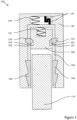
- FIG. 1 is a schematic view showing CRTe 120 as it is being lowered by the top drive of a drilling rig (not shown) onto a workpiece 110 (such as a section of pipe), and prior to the top of workpiece 110 contacting the bumper 150 of CRTe 120.
- Bumper spring 151 urges bumper 150 and lock pins 170 toward their respective locked positions.
- Cage spring 143 (which may be an air spring) is compressed between CRT mandrel 130 and CRT cage 140.
- Primary latch mechanism 134 is in its latched position, preventing CRT cage 140 from moving axially away from CRT mandrel 130 due to the force of compressed cage spring 143.
- CRT slips 160 are fully retracted away from workpiece 110.
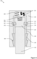
- FIG. 2 is a schematic view of CRTe 120 after it has been further lowered such that the top of workpiece 110 contacts CRT bumper 150 without sufficient force to compress bumper spring 151.
- FIG. 3 is a schematic view of CRTe 120 shown at the point when CRTe 120 has been further lowered such that bumper spring 151 is compressed and CRT bumper 150 is in its unlocked position relative to CRT cage 140.
- Primary latch mechanism 134 (which is a rotary latch mechanism) can be unlatched by using the top drive to apply set-down load and then to rotate CRT mandrel 130 in a first direction.
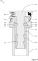
- FIG. 4 is a schematic view of CRTe 120 shown after primary latch mechanism 134 has been unlatched, and after CRTe 120 has been raised sufficiently to cause the lock pins 170 to move from their locked positions to their unlocked positions, urged by cam surfaces 132 of mandrel pockets 131 in CRT mandrel 130 and received by bumper pockets 152 in CRT bumper 150. Due to the relative axial motion between CRT mandrel 130 and CRT cage 140, CRT slips 160 extend toward workpiece 110.
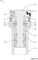
- FIG. 5 is a schematic view of CRTe 120 at the point where it has been raised sufficiently to cause CRT slips 160 to engage workpiece 110.
- FIG. 6 is a schematic view of CRTe 120 after it has been lowered to release workpiece 110.
- Primary latch mechanism 134 can be latched by applying set-down load and rotating CRT mandrel 130 in a second direction. After primary latch mechanism 134 has been latched, raising CRTe 120 will allow CRT bumper 150 to move to its locked position relative to CRT cage 140, urged by bumper spring 151. Cam surfaces 153 of bumper pockets 152 urge lock pins 170 to their locked position, received by mandrel pockets 131 in CRT mandrel 130. The state of CRTe 120 will then have returned to the state shown in FIG. 2 .
- CRTe 120 If CRTe 120 is rotated while being lowered onto workpiece 110 and is misaligned with workpiece 110, then torque and axial load may be transmitted through contact between CRT slips 160 and workpiece 110 prior to workpiece 110 contacting CRT bumper 150. If the combined torque and axial load transmitted through the contact between CRT slips 160 and workpiece 110 is sufficient to unlatch the primary latch mechanism, the lockout mechanism will prevent relative axial movement between CRT cage 140 and CRT mandrel 130, which would extend CRT slips 160 toward workpiece 110.
- the lockout mechanism may be configured to automatically unlock at a selected combined axial load and torque envelope (alternatively referred to as the lockout release envelope).
- the lockout release envelope is determined by the force balance on lock pins 170, which includes the selected taper angles of cam surface 153 of bumper pockets 152 and cam surface 132 of mandrel pockets 131, and the axial biasing force of bumper spring 151.
- FIGS. 7 through 12 schematically illustrate the operation of an exemplary embodiment of a lockout mechanism in accordance with the present disclosure, and incorporated into a CRTi 220 generally in accordance with the teachings of US 7,909,120 .
- FIG. 7 is a schematic view showing CRTi 220 as it is being lowered by the top drive of a drilling rig (not shown) onto a workpiece 210, and prior to the top of workpiece 210 contacting the CRT bumper 250 of CRTi 220.
- Bumper spring 251 urges CRT bumper 250 and lock pins 270 toward their respective locked positions.
- Cage spring 243 (which may be an air spring) is compressed between CRT mandrel 230 and CRT cage 240.
- Primary latch mechanism 234 is in its latched position, preventing CRT cage 240 from moving axially away from CRT mandrel 230 due to the force of compressed cage spring 243.
- CRT slips 260 are fully retracted away from workpiece 210.
- FIG. 8 is a schematic view of CRTi 220 after it has been further lowered such that the top of workpiece 210 contacts CRT bumper 250 without sufficient force to compress bumper spring 251.
- FIG. 9 is a schematic view of CRTi 220 shown at the point when CRTi 220 has been further lowered such that bumper spring 251 is compressed and CRT bumper 250 is in its unlocked position relative to CRT cage 240.
- Primary latch mechanism 234 (which is a rotary latch mechanism) can be unlatched by using the top drive to apply set-down load and then rotating CRT mandrel 230 in a first direction.
- FIG. 10 is a schematic view of CRTi 220 shown after primary latch mechanism 234 has been unlatched, and after CRTi 220 has been raised sufficiently to cause the lock pins 270 to move from their locked positions to their unlocked positions, urged by cam surfaces 232 of mandrel pockets 231 in CRT mandrel 230 and received by bumper pockets 252 in CRT bumper 250. Due to the relative axial motion between CRT mandrel 230 and CRT cage 240, CRT slips 260 extend toward workpiece 210.
- FIG. 11 is a schematic view of CRTi 220 at the point where it has been raised sufficiently to cause CRT slips 260 to engage workpiece 210.
- FIG. 12 is a schematic view of CRTi 220 after it has been lowered to release workpiece 210.
- Primary latch mechanism 234 can be latched by applying set-down load and rotating CRT mandrel 230 in a second direction. After primary latch mechanism 234 has been latched, raising CRTe 220 will allow CRT bumper 250 to move to its locked position relative to CRT cage 240, urged by bumper spring 251. Cam surfaces 253 of bumper pockets 252 urge lock pins 270 to their locked positions, received by pockets 231 of CRT mandrel 230. The state of CRTi 220 will then have returned to the state shown in FIG. 8 .
- CRTi 220 is rotated while being lowered onto workpiece 210 and is misaligned with workpiece 210, then torque and axial load may be transmitted through contact between CRT slips 260 and workpiece 210 prior to workpiece 210 contacting CRT bumper 250. If the combined torque and axial load transmitted through the contact between CRT slips 260 and workpiece 210 is sufficient to unlatch the primary latch mechanism, the lockout mechanism will prevent relative axial movement between CRT cage 240 and CRT mandrel 230, which would extend CRT slips 260 toward workpiece 210.
- the lockout mechanism may be configured to automatically unlock at a selected lockout release envelope determined by the force balance on lock pins 270, which includes the selected taper angles of cam surface 253 of bumper pockets 252 and cam surface 232 of mandrel pockets 231, and the axial biasing force of bumper spring 251.
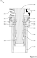
- FIG. 13 is a cross-section of a CRTe 320 generally in accordance with the teachings of US 7,909,120 ; similar to a CRTe shown in US 10,081,989 ; and including an embodiment of a lockout mechanism in accordance with this specification.
- Primary latch mechanism 334 of CRTe 320 is a rotary latch similar to that shown in US 8,424,939 .
- Cage spring 343 is an air spring.
- CRT mandrel 330, CRT cage 340, and CRT slips 360 are assemblies of multiple parts.
- the state of CRTe 320 and this lockout mechanism in FIG. 13 is similar to the state shown in FIG. 2 for CRTe 120, with lock pins 370 in their locked positions and with workpiece 310 in initial contact with bumper 350.
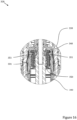
- FIG. 14 is a sectional detail of the lockout mechanism in CRTe 320 along a plane showing lock pins 370 in their locked positions, and bumper pockets 352 in CRT bumper 350 and mandrel pockets 331 in CRT mandrel assembly 330.
- the state of this lockout mechanism in CRTe 320 in FIG. 14 is similar to the state shown in FIG. 2 for the lockout mechanism of CRTe 120.
- FIG. 16 is a sectional detail of the lockout mechanism in CRTe 320 along a plane showing bumper springs 351.
- bumper springs 351 are compressed between CRT bumper 350 and CRT cage assembly 340 as CRT bumper 350 strokes from its locked position to its unlocked position.
- FIG. 17 is a sectional detail of the lockout mechanism in CRTe 320 along a plane showing shoulder bolts 354 securing CRT bumper 350 to CRT cage assembly 340.
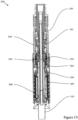
- FIG. 18 is a cross-section through a CRTe 420 generally in accordance with the teachings of US 7,909,120 (similar to a CRTe shown in US 10,081,989 ) and including another embodiment of a lockout mechanism in accordance with the present disclosure.
- Primary latch mechanism 434 of CRTe 420 is a rotary latch similar to that shown in US 8,424,939 , comprising upper latch hooks 435 and lower latch hooks 436.
- Cage spring 443 is an air spring.
- CRT mandrel 430, CRT cage 440, and CRT slips 460 are assemblies of multiple parts.
- the state of CRTe 420 and the lockout mechanism in FIG. 18 is similar to the state shown in FIG. 1 for CRTe 120, with lock pins 470 in their locked positions, primary latch mechanism 434 in its latched position, and with workpiece 410 prior to initial contact with CRT bumper 450.
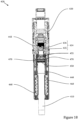
- FIG. 19 is a partial sectional detail of the lockout mechanism and primary latch mechanism 434 in CRTe 420, showing lock pins 470 in their locked positions; primary latch mechanism 434 in its latched position; bumper pockets 452 in CRT bumper 450; and mandrel pockets 431 in CRT mandrel assembly 430.
- the state of this lockout mechanism in CRTe 420 in FIG. 19 is similar to the state shown in FIG. 1 for the lockout mechanism of CRTe 120.
- FIG. 20 is a partial sectional detail of the lockout mechanism and primary latch mechanism 434 of CRTe 420 showing lock pins 470 in their unlocked positions; primary latch mechanism 434 in its unlatched position; bumper pockets 452 in CRT bumper 450; and CRT mandrel pockets 431 in CRT mandrel assembly 430.
- the state of this lockout mechanism in CRTe 420 in FIG. 20 is similar to the state shown in FIG. 3 for the lockout mechanism of CRTe 120.
- the lockout mechanism of CRTe 420 is configured with a mechanical linkage 445 acting between CRT bumper 450 and primary latch mechanism 434 such that axial force applied by workpiece 410 on CRT bumper 450 in excess of the axial biasing force of bumper spring 451 generates torque urging primary latch mechanism 434 to unlatch.
- Mechanical linkage 445 comprises track followers 444 on a radially-inward surface of CRT cage 440 that engage helical tracks 455 in a radially-outward surface of CRT bumper 450. The torque generated by mechanical linkage 445 is transmitted from track followers 444 to CRT cage 440 and then to lower latch hooks 436 of primary latch mechanism 434.
- the torque generated by mechanical linkage 445 is also transmitted from helical tracks 455 in CRT bumper 450 to workpiece 410 through frictional contact with CRT bumper 450 to the drilling rig (not shown) to the upper end of CRTe 420, and then to upper latch hooks 435 of primary latch mechanism 434.
- any form of the word "comprise” is to be understood in its non-limiting sense to mean that any element or feature following such word is included, but elements or features not specifically mentioned are not excluded.
- a reference to an element or feature by the indefinite article “a” does not exclude the possibility that more than one such element or feature is present, unless the context clearly requires that there be one and only one such element or feature.
- any use herein of any form of the terms “connect”, “engage”, “couple”, “attach”, or any other term describing an interaction between elements is not meant to limit the interaction to direct interaction between the subject elements, and may also include indirect interaction between the elements such as through secondary or intermediary structure.
- any reference to an element being "generally cylindrical” is intended to denote that the element in question would appear substantially cylindrical in transverse cross-section, although the cross-sectional configuration of the element may vary along its length.
Landscapes
- Engineering & Computer Science (AREA)
- Life Sciences & Earth Sciences (AREA)
- Geology (AREA)
- Mining & Mineral Resources (AREA)
- General Life Sciences & Earth Sciences (AREA)
- Fluid Mechanics (AREA)
- Environmental & Geological Engineering (AREA)
- Physics & Mathematics (AREA)
- Geochemistry & Mineralogy (AREA)
- Mechanical Engineering (AREA)
- Marine Sciences & Fisheries (AREA)
- Bending Of Plates, Rods, And Pipes (AREA)
- Earth Drilling (AREA)
- Automatic Tool Replacement In Machine Tools (AREA)
- Yarns And Mechanical Finishing Of Yarns Or Ropes (AREA)
- Manipulator (AREA)
Claims (8)
- Mécanisme de verrouillage pour un outil de pose de tubage (OPT) (120) destiné à entrer en prise avec une pièce tubulaire (110), ledit OPT ayant un axe longitudinal et comprenant une cage d'OPT (140) globalement cylindrique comportant une paroi de cage d'OPT ; un mandrin d'OPT (130) globalement cylindrique, aligné de manière coaxiale avec la cage d'OPT ; et des cales d'OPT (160) supportées par la cage d'OPT, lesdites cales d'OPT étant propres à être déplacées radialement en réponse à un déplacement axial relatif entre le mandrin d'OPT et la cage d'OPT pour entrer en prise avec une surface choisie de la pièce ; et un mécanisme d'accrochage principal d'OPT (134) ; et ledit mécanisme de verrouillage comprenant :(a) un amortisseur d'OPT (150) propre à être adapté de manière coulissante dans la cage d'OPT et propre à être actionné pour se déplacer axialement entre une position verrouillée et une position déverrouillée, ledit amortisseur d'OPT étant sollicité par un ressort d'amortisseur (151) conçu pour exercer une force de sollicitation axiale suffisante pour résister à une charge axiale choisie lorsque l'amortisseur d'OPT est déplacé de la position verrouillée à la position déverrouillée par son entrée en contact avec l'extrémité de la pièce ;(b) une ou plusieurs goupilles de verrouillage (170) propres à être disposées de manière radialement coulissante dans des trous de guidage de goupilles de verrouillage correspondants formés à travers la paroi de cage d'OPT et propres à être déplacées entre :• une position verrouillée, correspondant à la position verrouillée de l'amortisseur d'OPT, dans laquelle les goupilles de verrouillage se logent dans des cavités de mandrin (131) correspondantes formées dans le mandrin d'OPT ; et• une position déverrouillée, correspondant à la position déverrouillée de l'amortisseur d'OPT, dans laquelle les goupilles de verrouillage se logent dans des cavités d'amortisseur (152) correspondantes formées dans l'amortisseur d'OPT ;dans lequel :(i) les cavités de mandrin et les trous de guidage de goupilles de verrouillage sont agencés de telle sorte que les goupilles de verrouillage, lorsqu'elles se trouvent dans leurs positions verrouillées :• empêchent un déplacement axial relatif entre le mandrin d'OPT et la cage d'OPT ; et• maintiennent la cage d'OPT dans une certaine position axiale relativement au mandrin d'OPT, les cales d'OPT étant rétractées relativement à la pièce ;(ii) chaque cavité de mandrin comprend une surface à effet de came (132) conçue pour provoquer un déplacement des goupilles de verrouillage vers leurs positions déverrouillées lorsque la cage d'OPT se déplace axialement relativement au mandrin d'OPT dans le sens amenant les cales d'OPT à entrer en prise avec la pièce ;(iii) chaque cavité d'amortisseur comprend une surface à effet de came (152) conçue pour provoquer un déplacement des goupilles de verrouillage vers leurs positions verrouillées en réponse à la force axiale appliquée à l'amortisseur d'OPT par le ressort d'amortisseur ;(iv) la force de sollicitation axiale du ressort d'amortisseur est choisie de telle sorte que le ressort d'amortisseur puisse appliquer une force axiale suffisante à l'amortisseur d'OPT pour maintenir les goupilles de verrouillage dans leurs positions verrouillées lorsqu'aucune pièce n'est en contact avec l'amortisseur d'OPT ; et(v) l'application d'une force axiale par la pièce à l'amortisseur d'OPT suffisante pour déplacer axialement l'amortisseur d'OPT et surmonter la force de sollicitation axiale du ressort d'amortisseur déplacera l'amortisseur d'OPT jusqu'à sa position déverrouillée, ce qui permettra un déplacement des goupilles de verrouillage de leurs positions verrouillées à leurs positions déverrouillées, et de sorte qu'elles pénètrent dans les cavités d'amortisseur correspondantes.
- Mécanisme de verrouillage selon la revendication 1, dans lequel la surface choisie de la pièce est une surface extérieure de la pièce.
- Mécanisme de verrouillage selon la revendication 1, dans lequel la surface choisie de la pièce est une surface intérieure de la pièce.
- Mécanisme de verrouillage selon l'une quelconque des revendications 1 à 3, comprenant, en outre, un moyen de liaison mécanique agissant entre l'amortisseur et le mécanisme d'accrochage principal d'OPT de telle sorte qu'une force axiale appliquée par la pièce sur l'amortisseur excédant la force de sollicitation axiale du ressort d'amortisseur générera un couple provoquant le décrochage du mécanisme d'accrochage principal d'OPT.
- Mécanisme de verrouillage selon la revendication 4, dans lequel le moyen de liaison mécanique comprend des filets hélicoïdaux conjugués.
- Mécanisme de verrouillage selon la revendication 4, dans lequel le moyen de liaison mécanique comprend un élément suiveur de guide hélicoïdal.
- Mécanisme de verrouillage selon l'une quelconque des revendications 1 à 6, dans lequel les angles d'inclinaison des surfaces à effet de came des cavités d'amortisseur et des cavités de mandrin et la force de sollicitation axiale du ressort d'amortisseur sont choisis de telle sorte que le mécanisme de verrouillage se déverrouille automatiquement en réponse à l'application d'une combinaison choisie de couple et de charge axiale.
- Mécanisme de verrouillage selon l'une quelconque des revendications 1 à 7, dans lequel le ressort d'amortisseur est choisi dans le groupe constitué des ressorts hélicoïdaux, des ressorts ondulés, des empilements de rondelles Belleville, des ressorts pneumatiques, et des chambres hydrauliques raccordées à des accumulateurs.
Applications Claiming Priority (2)
| Application Number | Priority Date | Filing Date | Title |
|---|---|---|---|
| US202062971733P | 2020-02-07 | 2020-02-07 | |
| PCT/CA2021/000008 WO2021174333A1 (fr) | 2020-02-07 | 2021-02-06 | Mécanisme de verrouillage pour outil de prise |
Publications (4)
| Publication Number | Publication Date |
|---|---|
| EP4100615A1 EP4100615A1 (fr) | 2022-12-14 |
| EP4100615A4 EP4100615A4 (fr) | 2024-02-28 |
| EP4100615B1 true EP4100615B1 (fr) | 2025-04-30 |
| EP4100615C0 EP4100615C0 (fr) | 2025-04-30 |
Family
ID=77612521
Family Applications (1)
| Application Number | Title | Priority Date | Filing Date |
|---|---|---|---|
| EP21764720.5A Active EP4100615B1 (fr) | 2020-02-07 | 2021-02-06 | Mécanisme de verrouillage pour outil de prise |
Country Status (6)
| Country | Link |
|---|---|
| US (1) | US11332985B1 (fr) |
| EP (1) | EP4100615B1 (fr) |
| AU (1) | AU2021232212B2 (fr) |
| CA (1) | CA3162407A1 (fr) |
| MX (1) | MX2022009660A (fr) |
| WO (1) | WO2021174333A1 (fr) |
Families Citing this family (3)
| Publication number | Priority date | Publication date | Assignee | Title |
|---|---|---|---|---|
| CA3191692C (fr) * | 2020-10-26 | 2023-11-14 | Maurice William Slack | Liaison axiale a longueur variable pour outils de pose tubulaires |
| US12312881B2 (en) * | 2021-09-03 | 2025-05-27 | Saudi Arabian Oil Company | Intelligent powerslip and power lock system for running and retrieving tubulars from a wellbore |
| US20250320784A1 (en) * | 2024-04-10 | 2025-10-16 | Keller North America, Inc. | Collapsible casing tightener and method of use |
Family Cites Families (12)
| Publication number | Priority date | Publication date | Assignee | Title |
|---|---|---|---|---|
| US2507127A (en) * | 1948-12-27 | 1950-05-09 | Standard Oil Dev Co | Automatic drill pipe elevator |
| US3275368A (en) * | 1964-05-27 | 1966-09-27 | Rowe A Plunk | Releasable retrieving tool |
| GB2416794B (en) * | 2003-04-02 | 2007-11-21 | Enventure Global Technology | Apparatus and method for cutting a tubular member |
| WO2006116870A1 (fr) | 2005-05-03 | 2006-11-09 | Noetic Engineering Inc. | Outil de prehension |
| CN102099542B (zh) | 2008-07-18 | 2014-03-12 | 诺埃提克技术公司 | 为夹持工具提供改进操作范围和能力的三凸轮轴向扩展 |
| US8261818B2 (en) * | 2009-05-20 | 2012-09-11 | Vetco Gray Inc. | Self-inserting seal assembly |
| GB201014088D0 (en) * | 2010-08-23 | 2010-10-06 | Aker Subsea Ltd | Subsea running tool with emergency release |
| WO2014056092A1 (fr) * | 2012-10-09 | 2014-04-17 | Noetic Technologies Inc. | Outil d'accrochage d'éléments tubulaires |
| US9896891B2 (en) * | 2013-10-17 | 2018-02-20 | DrawWorks LP | Top drive operated casing running tool |
| US9932781B2 (en) * | 2014-04-22 | 2018-04-03 | Baker Hughes, A Ge Company, Llc | Casing spear with mechanical locking feature |
| RU2020107408A (ru) * | 2017-07-20 | 2021-08-20 | Ноэтик Текнолоджиз Инк. | Высвобождающий поворотный элеватор механизм, приводимый в действие осевой нагрузкой |
| EP3911834B1 (fr) | 2019-01-19 | 2025-03-12 | Noetic Technologies Inc. | Mécanismes de libération de verrous rotatifs actionnés par charge axiale pour outils de passage de tubage |
-
2021
- 2021-02-06 WO PCT/CA2021/000008 patent/WO2021174333A1/fr not_active Ceased
- 2021-02-06 AU AU2021232212A patent/AU2021232212B2/en active Active
- 2021-02-06 EP EP21764720.5A patent/EP4100615B1/fr active Active
- 2021-02-06 US US17/432,831 patent/US11332985B1/en active Active
- 2021-02-06 MX MX2022009660A patent/MX2022009660A/es unknown
- 2021-03-11 CA CA3162407A patent/CA3162407A1/fr active Pending
Also Published As
| Publication number | Publication date |
|---|---|
| MX2022009660A (es) | 2022-09-09 |
| US11332985B1 (en) | 2022-05-17 |
| EP4100615A1 (fr) | 2022-12-14 |
| CA3162407A1 (fr) | 2021-09-10 |
| AU2021232212B2 (en) | 2025-02-27 |
| WO2021174333A1 (fr) | 2021-09-10 |
| EP4100615C0 (fr) | 2025-04-30 |
| AU2021232212A1 (en) | 2022-09-08 |
| US20220154540A1 (en) | 2022-05-19 |
| EP4100615A4 (fr) | 2024-02-28 |
Similar Documents
| Publication | Publication Date | Title |
|---|---|---|
| EP2313600B1 (fr) | Extension axiale a triple came pour constituer un outil de saisie avec une capacite et une plage de fonctionnement ameliorees | |
| EP4100615B1 (fr) | Mécanisme de verrouillage pour outil de prise | |
| EP1877644B1 (fr) | Outil de prehension | |
| US11313183B2 (en) | Axial-load-actuated rotary latch release mechanisms for casing running tools | |
| US11299940B2 (en) | Axial-stroke-actuated rotary latch release mechanism | |
| US20220259930A1 (en) | Internal latch release mechanism for externally-gripping casing running tools | |
| EP4232685B1 (fr) | Liaison axiale à longueur variable pour outils de pose tubulaires | |
| CN119137345A (zh) | 闩锁释放机构 | |
| CA3261895C (fr) | Mécanisme d'embrayage pour outils de préhension | |
| US12173761B1 (en) | Clutch mechanism for gripping tools | |
| HK1155788B (en) | Tricam axial extension to provide gripping tool with improved operational range and capacity | |
| CN116490671A (zh) | 用于下管工具的可变长度轴向联动装置 |
Legal Events
| Date | Code | Title | Description |
|---|---|---|---|
| STAA | Information on the status of an ep patent application or granted ep patent |
Free format text: STATUS: THE INTERNATIONAL PUBLICATION HAS BEEN MADE |
|
| PUAI | Public reference made under article 153(3) epc to a published international application that has entered the european phase |
Free format text: ORIGINAL CODE: 0009012 |
|
| STAA | Information on the status of an ep patent application or granted ep patent |
Free format text: STATUS: REQUEST FOR EXAMINATION WAS MADE |
|
| 17P | Request for examination filed |
Effective date: 20220824 |
|
| AK | Designated contracting states |
Kind code of ref document: A1 Designated state(s): AL AT BE BG CH CY CZ DE DK EE ES FI FR GB GR HR HU IE IS IT LI LT LU LV MC MK MT NL NO PL PT RO RS SE SI SK SM TR |
|
| DAV | Request for validation of the european patent (deleted) | ||
| DAX | Request for extension of the european patent (deleted) | ||
| A4 | Supplementary search report drawn up and despatched |
Effective date: 20240125 |
|
| RIC1 | Information provided on ipc code assigned before grant |
Ipc: E21B 19/16 20060101ALI20240119BHEP Ipc: E21B 31/20 20060101ALI20240119BHEP Ipc: E21B 31/18 20060101ALI20240119BHEP Ipc: E21B 23/00 20060101ALI20240119BHEP Ipc: E21B 19/06 20060101ALI20240119BHEP Ipc: E21B 19/07 20060101AFI20240119BHEP |
|
| GRAP | Despatch of communication of intention to grant a patent |
Free format text: ORIGINAL CODE: EPIDOSNIGR1 |
|
| STAA | Information on the status of an ep patent application or granted ep patent |
Free format text: STATUS: GRANT OF PATENT IS INTENDED |
|
| INTG | Intention to grant announced |
Effective date: 20241209 |
|
| RIN1 | Information on inventor provided before grant (corrected) |
Inventor name: SLACK, MAURICE W. |
|
| GRAS | Grant fee paid |
Free format text: ORIGINAL CODE: EPIDOSNIGR3 |
|
| GRAA | (expected) grant |
Free format text: ORIGINAL CODE: 0009210 |
|
| STAA | Information on the status of an ep patent application or granted ep patent |
Free format text: STATUS: THE PATENT HAS BEEN GRANTED |
|
| AK | Designated contracting states |
Kind code of ref document: B1 Designated state(s): AL AT BE BG CH CY CZ DE DK EE ES FI FR GB GR HR HU IE IS IT LI LT LU LV MC MK MT NL NO PL PT RO RS SE SI SK SM TR |
|
| REG | Reference to a national code |
Ref country code: CH Ref legal event code: EP Ref country code: GB Ref legal event code: FG4D |
|
| REG | Reference to a national code |
Ref country code: DE Ref legal event code: R096 Ref document number: 602021030058 Country of ref document: DE |
|
| REG | Reference to a national code |
Ref country code: IE Ref legal event code: FG4D |
|
| U01 | Request for unitary effect filed |
Effective date: 20250507 |
|
| U07 | Unitary effect registered |
Designated state(s): AT BE BG DE DK EE FI FR IT LT LU LV MT NL PT RO SE SI Effective date: 20250514 |
|
| PG25 | Lapsed in a contracting state [announced via postgrant information from national office to epo] |
Ref country code: ES Free format text: LAPSE BECAUSE OF FAILURE TO SUBMIT A TRANSLATION OF THE DESCRIPTION OR TO PAY THE FEE WITHIN THE PRESCRIBED TIME-LIMIT Effective date: 20250430 |
|
| PG25 | Lapsed in a contracting state [announced via postgrant information from national office to epo] |
Ref country code: GR Free format text: LAPSE BECAUSE OF FAILURE TO SUBMIT A TRANSLATION OF THE DESCRIPTION OR TO PAY THE FEE WITHIN THE PRESCRIBED TIME-LIMIT Effective date: 20250731 |
|
| PG25 | Lapsed in a contracting state [announced via postgrant information from national office to epo] |
Ref country code: PL Free format text: LAPSE BECAUSE OF FAILURE TO SUBMIT A TRANSLATION OF THE DESCRIPTION OR TO PAY THE FEE WITHIN THE PRESCRIBED TIME-LIMIT Effective date: 20250430 |
|
| PG25 | Lapsed in a contracting state [announced via postgrant information from national office to epo] |
Ref country code: HR Free format text: LAPSE BECAUSE OF FAILURE TO SUBMIT A TRANSLATION OF THE DESCRIPTION OR TO PAY THE FEE WITHIN THE PRESCRIBED TIME-LIMIT Effective date: 20250430 |
|
| PG25 | Lapsed in a contracting state [announced via postgrant information from national office to epo] |
Ref country code: RS Free format text: LAPSE BECAUSE OF FAILURE TO SUBMIT A TRANSLATION OF THE DESCRIPTION OR TO PAY THE FEE WITHIN THE PRESCRIBED TIME-LIMIT Effective date: 20250731 |
|
| PG25 | Lapsed in a contracting state [announced via postgrant information from national office to epo] |
Ref country code: IS Free format text: LAPSE BECAUSE OF FAILURE TO SUBMIT A TRANSLATION OF THE DESCRIPTION OR TO PAY THE FEE WITHIN THE PRESCRIBED TIME-LIMIT Effective date: 20250830 |
|
| PG25 | Lapsed in a contracting state [announced via postgrant information from national office to epo] |
Ref country code: SM Free format text: LAPSE BECAUSE OF FAILURE TO SUBMIT A TRANSLATION OF THE DESCRIPTION OR TO PAY THE FEE WITHIN THE PRESCRIBED TIME-LIMIT Effective date: 20250430 |
|
| PG25 | Lapsed in a contracting state [announced via postgrant information from national office to epo] |
Ref country code: CZ Free format text: LAPSE BECAUSE OF FAILURE TO SUBMIT A TRANSLATION OF THE DESCRIPTION OR TO PAY THE FEE WITHIN THE PRESCRIBED TIME-LIMIT Effective date: 20250430 |
|
| PG25 | Lapsed in a contracting state [announced via postgrant information from national office to epo] |
Ref country code: SK Free format text: LAPSE BECAUSE OF FAILURE TO SUBMIT A TRANSLATION OF THE DESCRIPTION OR TO PAY THE FEE WITHIN THE PRESCRIBED TIME-LIMIT Effective date: 20250430 |
|
| PLBE | No opposition filed within time limit |
Free format text: ORIGINAL CODE: 0009261 |
|
| STAA | Information on the status of an ep patent application or granted ep patent |
Free format text: STATUS: NO OPPOSITION FILED WITHIN TIME LIMIT |
|
| REG | Reference to a national code |
Ref country code: CH Ref legal event code: L10 Free format text: ST27 STATUS EVENT CODE: U-0-0-L10-L00 (AS PROVIDED BY THE NATIONAL OFFICE) Effective date: 20260311 |
|
| U20 | Renewal fee for the european patent with unitary effect paid |
Year of fee payment: 6 Effective date: 20260216 |
|
| 26N | No opposition filed |
Effective date: 20260202 |
|
| PGFP | Annual fee paid to national office [announced via postgrant information from national office to epo] |
Ref country code: GB Payment date: 20260216 Year of fee payment: 6 |
|
| PGFP | Annual fee paid to national office [announced via postgrant information from national office to epo] |
Ref country code: NO Payment date: 20260218 Year of fee payment: 6 |