EP4100352B1 - Verfahren und vorrichtung zur bestimmung von geschätzten realen abmessungen einer aufzugskabine - Google Patents
Verfahren und vorrichtung zur bestimmung von geschätzten realen abmessungen einer aufzugskabine Download PDFInfo
- Publication number
- EP4100352B1 EP4100352B1 EP21702023.9A EP21702023A EP4100352B1 EP 4100352 B1 EP4100352 B1 EP 4100352B1 EP 21702023 A EP21702023 A EP 21702023A EP 4100352 B1 EP4100352 B1 EP 4100352B1
- Authority
- EP
- European Patent Office
- Prior art keywords
- elevator car
- real dimensions
- rectangular area
- area
- elevator
- Prior art date
- Legal status (The legal status is an assumption and is not a legal conclusion. Google has not performed a legal analysis and makes no representation as to the accuracy of the status listed.)
- Active
Links
Images


Classifications
-
- B—PERFORMING OPERATIONS; TRANSPORTING
- B66—HOISTING; LIFTING; HAULING
- B66B—ELEVATORS; ESCALATORS OR MOVING WALKWAYS
- B66B5/00—Applications of checking, fault-correcting, or safety devices in elevators
- B66B5/0087—Devices facilitating maintenance, repair or inspection tasks
-
- B—PERFORMING OPERATIONS; TRANSPORTING
- B25—HAND TOOLS; PORTABLE POWER-DRIVEN TOOLS; MANIPULATORS
- B25J—MANIPULATORS; CHAMBERS PROVIDED WITH MANIPULATION DEVICES
- B25J11/00—Manipulators not otherwise provided for
-
- B—PERFORMING OPERATIONS; TRANSPORTING
- B25—HAND TOOLS; PORTABLE POWER-DRIVEN TOOLS; MANIPULATORS
- B25J—MANIPULATORS; CHAMBERS PROVIDED WITH MANIPULATION DEVICES
- B25J19/00—Accessories fitted to manipulators, e.g. for monitoring, for viewing; Safety devices combined with or specially adapted for use in connection with manipulators
- B25J19/02—Sensing devices
- B25J19/021—Optical sensing devices
- B25J19/022—Optical sensing devices using lasers
-
- G—PHYSICS
- G01—MEASURING; TESTING
- G01S—RADIO DIRECTION-FINDING; RADIO NAVIGATION; DETERMINING DISTANCE OR VELOCITY BY USE OF RADIO WAVES; LOCATING OR PRESENCE-DETECTING BY USE OF THE REFLECTION OR RERADIATION OF RADIO WAVES; ANALOGOUS ARRANGEMENTS USING OTHER WAVES
- G01S17/00—Systems using the reflection or reradiation of electromagnetic waves other than radio waves, e.g. lidar systems
- G01S17/88—Lidar systems specially adapted for specific applications
- G01S17/89—Lidar systems specially adapted for specific applications for mapping or imaging
Definitions
- the present invention relates to a method and a device for determining estimated real dimensions of an elevator car. Furthermore, the invention relates to a maintenance arrangement to be applied in maintaining an elevator. Finally, the invention relates to a computer program product configured for implementing the proposed method and to a computer readable medium having stored thereon such computer program product.
- CN 207908967 U discloses a method and a computing device for determining estimated real dimensions of an elevator car using a laser radar device used in an automated guided vehicle.
- an elevator car may be displaced between various levels for transporting passengers and/or goods for example between different floors in a building.
- the elevator is generally configured for implementing various functions. Such functions may relate to a normal operation of the elevator and may include for example controlling intended displacements of the elevator car, controlling precise stopping of the elevator car at floors, providing information to passengers, etc.
- Other functions may relate to an emergency operation and may include for example controlling emergency actions such as activating emergency brakes of the elevator car, arranging for emergency help and maintenance, etc. Further functions may relate to regular maintenance of the elevator.
- All functions of an elevator may have to be tested before normal operation of the elevator is actually started.
- a specialised maintenance technician may have to perform such tests.
- Such tests may include for example intentionally displacing the elevator car to various positions using various control mechanisms such as activating landing operation panels at various floors and/or activating a car operation panel in the elevator car.
- the technician may have to spend a lot of time and efforts e.g. for travelling throughout the building using the elevator.
- robots may be configured for travelling throughout a building using the elevator.
- the robot may test functions of the elevator e.g. by performing actions which, during later normal operation or maintenance, will be performed by passengers or by a technician.
- a robot may have to enter and exit the elevator car at various floors, activate landing operation panels and/or car operation panels, etc.
- the robot may have to be able to autonomously navigate throughout the building and its elevator. Accordingly, the robot may require some information about its environment. Particularly, the robot may require information about positions and dimensions of floors, elevator doors, elevator cars, etc.
- the robot may require precise information about the dimensions of the elevator car. Such information may be needed for enabling the robot to move throughout the elevator car. Particularly, such information may help the robot to move to positions within the elevator car where the robot does e.g. not disturb human passengers in the elevator car, i.e. to "behave” in a "social” manner. For example, the robot may move to a position at a wall or in a corner of the elevator cabin instead of standing right in the middle of the elevator car or even blocking an entry/exit area of the elevator car.
- the robot may comprise one or more sensors.
- robots may comprise a lidar system comprising a lidar sensor for determining information about its environment.
- "Lidar” stands for light detection and ranging.
- lidar is an optical technique in which light is emitted and is then detected upon being reflected at a target.
- lidar is a surveying method that may measure distances to a target by illuminating the target with laser light and measure the reflected light with a sensor.
- the robot may comprise other types of sensors such as ultrasonic sensors, mechanical sensors, etc. as well as actuators e.g. for activating elevator functions.
- erroneous observations may occur at least under some conditions. For example, it has been observed that upon using its lidar system, a robot may have problems in determining dimensions of an elevator car correctly.
- a method for determining estimated real dimensions of an elevator car comprises at least the following steps, preferably in the indicated order:
- a computing device for determining estimated real dimensions of an elevator car is proposed.
- the computing device is configured for executing the method according to an embodiment of the first aspect of the invention.
- a maintenance arrangement for providing support in maintaining an elevator arrangement.
- the maintenance arrangement comprises a mapping robot and a computing device according to an embodiment of the second aspect of the invention.
- the mapping robot comprises a mobilisation unit and a lidar sensor.
- the robot is configured for traveling along an accessible space driven by the mobilisation unit and for acquiring a virtual 2-dimensional map of a surrounding of the robot using the lidar sensor.
- the computing device is configured for determining estimated real dimensions of an elevator car based on a virtual 2-dimensional map of the elevator car acquired with the lidar sensor of the robot.
- a computer program product comprises computer readable instructions instructing a processor for executing or controlling the method according to an embodiment of the first aspect of the invention.
- lidar systems sometimes provide erroneous or imprecise results upon detecting their environment. This particularly applies in cases where mirrors are present in the environment. The mirrors generate a mirrored representation of the environment which may disturb the lidar system.
- a lidar system used by a robot for determining the environment in an elevator arrangement may be disturbed by mirrors which in many cases cover part of walls in an elevator car. Accordingly, based on the information provided by the lidar system, the robot may assume that estimated dimensions of the elevator car are larger than they are in reality.
- a specific approach is proposed herein. Such an approach is particularly applicable for determining estimated real dimensions of an elevator car as it may benefit from specific preconditions and/or assumptions applicable for such elevator cars. For example, it may generally be assumed that the elevator car has a substantially rectangular horizontal cross-section (sometimes also referred to as footprint). Furthermore, it may generally be assumed that mirrors only cover partial areas of entire walls within the elevator car while some other areas remaining non-mirrored. For example, a mirror may be surrounded by a non-mirrored area or may be held by a non-mirroring frame.
- the method for determining estimated real dimensions of an elevator car as proposed herein starts with acquiring a virtual 2-dimensional map of the elevator car based on data provided by a lidar sensor.
- Such 2-dimensional map may be acquired by the lidar sensor upon emitting a laser beam along a single plane, particularly along a horizontal plane.
- a laser beam may be emitted by a laser source.
- Such laser beam may then be deflected into a direction included in the horizontal plane using for example a mirror.
- the mirror may be rotated such that the laser beam is deflected in all directions along the horizontal plane, i.e. the laser beam is successively deflected in 360° within the horizontal plane.
- reflections of the laser beam may be detected in the lidar sensor.
- the virtual 2-dimensional map of the lidar sensor's environment may be generated.
- the lidar sensor being located within an elevator car
- Such 2-dimensional map represents reflection surfaces from which laser light emitted by the lidar sensor is reflected.
- Such reflection surfaces generally correspond to surfaces of the vertical walls of the elevator car.
- the lidar sensor generally does not detect its distance to this wall, but, as the mirror reflects an image of an opposite wall of the elevator car, the lidar sensor may detect an erroneous distance with regard to the reflected wall.
- the method proposed herein continues with specifically analysing the acquired virtual 2-dimensional map.
- the starting area may correspond to a single pixel in an image representing the virtual 2-dimensional map.
- the starting area may be the smallest area for which information may be provided within the virtual 2-dimensional map.
- Such pixel or starting area generally is or may be interpreted as being rectangular.
- the starting area should be defined at a position within the real dimensions of the elevator car.
- the starting area should not be defined within a virtual space generated upon reflecting walls of the elevator car in a mirror covering one of these walls, such virtual space being outside the real footprint of the elevator car.
- the starting area should be defined somewhere within the real dimensions of the elevator car, i.e. within the real footprint of the elevator car.
- this starting area may be defined based on prior knowledge data indicating additional information about the real dimensions of the elevator car.
- the starting area upon defining the position of the starting area, other sources of information about the real dimensions of the elevator car may be used.
- additional information is not included in, or analytically derivable from, the virtual 2-dimensional map itself.
- the prior knowledge data indicating such additional information may be acquired from a map or plan representing a layout or footprint of the building in which the elevator is situated. Using such layout or footprint, it may be estimated where the elevator car is situated and where its real dimensions roughly end. Accordingly, the starting area may be defined within such estimated real dimensions of the elevator car.
- a human technician may determine the position of the starting area based on prior knowledge data and/or based on other criteria. The technician may then input the information about such position into a computing device configured for executing other steps of the method proposed herein.
- the computing device itself may implement an algorithm with which prior knowledge data may be analysed such that the starting area may be positioned within the real dimensions of the elevator car.
- the computing device may use image analysis for analysing a map or plan representing the layout or footprint of the building accommodating the elevator for determining a location within the real dimensions of the elevator car.
- the starting area may be defined at or close to a geometric centre of the elevator car.
- the starting area should preferably not be defined at or close to one of the walls surrounding an interior space of the elevator car but should be defined sufficiently remote from such walls. Accordingly, the starting area should be defined sufficiently remote from any mirror covering a part of such wall.
- "at or close to a geometric centre of the elevator car” may be interpreted as being closer to the geometric centre of the elevator car than to one of the walls.
- the starting area should be defined with edges of the rectangular area being parallel to walls of the elevator car.
- the starting area having itself a rectangular geometry should preferably be oriented such that its edges are parallel to the walls of the elevator car also having a rectangular geometry.
- a misalignment of such parallel arrangement should be smaller than 20°, more preferably smaller than 10° or even smaller than 5°.
- the rectangular area of the starting area is successively extended by one pixel in each of four extension directions.
- each extension direction is orthogonal to one of the edges of the rectangular starting area.
- the starting area may be a single pixel within the virtual 2-dimensional map of the elevator car
- the rectangle defining the starting area is extended in each extension direction such as to include one pixel above, one pixel below, one pixel to the left and one pixel to the right with regard to the initial pixel defining the starting area.
- the entire extended area of the rectangle includes corner pixels connecting the mentioned extended pixels.
- the edges of the rectangular starting area are displaced in a parallel manner by the width of one pixel in each of the four extension directions.
- Such extending of the rectangular area may be repeated several times. Particularly, the described extending of the rectangular area in all extension directions may be repeated until at least one of the edges of the rectangular area reaches one of the reflection surfaces indicated in the virtual 2-dimensional map.
- any pixel in one of the extension directions corresponds to one of the reflection surfaces indicated in the virtual 2-dimensional map
- extending the rectangular area in this direction should be stopped, i.e. should not be executed in subsequent steps of extending the rectangular area. Instead, in such subsequent steps, the rectangular area should only be extended by one pixel in each of the remaining extension directions.
- the entire procedure of successively extending the rectangular area therefore generally begins with extending the rectangular area in all four extension directions until such extending is "blocked" in at least one of the extension directions by the extended rectangular area reaching one of the reflection surfaces representing walls, i.e. lateral limits, of the elevator car.
- the rectangular area is then successively further extended in the remaining extension directions until also these extending actions are sooner or later "blocked" upon reaching other ones of the reflection surfaces representing one of the other walls of the elevator car.
- the rectangular area is fully extended to a maximum in each of the extension directions.
- Such fully extended rectangular area then represents the estimated real dimensions of the elevator car to be determined in the proposed method.
- the proposed method allows determining the estimated real dimensions of the elevator car with high precision.
- the fully extended rectangular obtained upon extending the initial starting area in each of four extension directions to a maximum generally corresponds to a high degree to the exact real dimensions of the elevator car.
- Results of the proposed method are particularly reliable as long as some preconditions and/or assumptions apply. Particularly, it is generally necessary that the starting area is selected such that its position is inside the real dimensions of the elevator car. Furthermore, it may be helpful that the starting area is positioned at a suitable starting location, preferably sufficiently far away from a mirrored wall of the elevator car, and or that the orientation of the rectangular starting area is aligned with the generally rectangular footprint of the elevator car.
- the proposed algorithm may sometimes not provide correct results.
- the algorithm may result in areas represented within the virtual 2-dimensional map and being actually outside the real dimensions of the elevator car being erroneously interpreted as being part of real dimensions of the elevator car.
- steps (b) to (c) of the proposed method may be repeated in iterations with defining the starting area in step (b) at various positions located within the real dimensions of the elevator car.
- the finally resulting fully extended rectangular area is developed from different initial starting areas which at least differ with respect to their position within the real dimensions of the elevator car.
- the starting area in a first iteration, may be successively extended until reaching the fully extended rectangular area. In one or more subsequent iterations, the location of the starting area may then be set such that it is located within this fully extended rectangular area of the first iteration. In this way, a likelihood of a final result of the proposed method being correct may be increased.
- step (d) of the proposed method in case all iterations result in a same fully extended rectangular area, such fully extended rectangular area may be determined as representing the estimated real dimensions of the elevator car.
- a most-likely solution may be selected among the differing fully extended rectangular areas taking into account additional prior knowledge and the most-likely solution may be determined as the estimated real dimensions of the elevator car.
- a most-likely solution among the differing resulting fully extended rectangular areas may be selected by taking into account further information.
- further information may be prior knowledge which relates for example to typical geometries of the elevator cars, typical artefacts included in virtual 2-dimensional maps acquired based on lidar data, etc.
- the most-likely solution may be selected based on a most reasonable aspect ratio in such rectangular geometry and/or a most reasonable size of the rectangular geometry.
- each of multiple determined fully extended areas not including the starting area defined in the first iteration may be disregarded upon the determining the estimated real dimensions of the elevator car.
- this fully extended rectangular area may not represent the entire real dimensions of the elevator car but, instead, either represents only a part of this entire real dimensions or is even at least partially located within a mirrored portion of the virtual 2-dimensional map of the elevator car. Accordingly, such fully extended rectangular area may be disregarded upon finding the real dimensions of the elevator car.
- An embodiment of the computing device may comprise a processor for processing computer readable instructions and a memory for storing such computer readable instructions and/or for storing data to be processed.
- the computing device may comprise interfaces or data communication lines via which data and/or signals may be exchanged with other devices such as for example with the lidar sensor and/or with other components in a larger device or robot.
- the computing device is adapted for executing or controlling the method proposed herein. Accordingly, by operating the computing device, the estimated real dimensions of the elevator car may be determined.
- Such computing device may be part of a maintenance arrangement according to an embodiment of the third aspect of the invention.
- Such maintenance arrangement may provide support in maintaining an elevator arrangement.
- Such maintenance arrangements may provide support in checking functionalities of the elevator arrangement.
- the maintenance arrangement comprises a mapping robot as well as the proposed computing device.
- the mapping robot comprises a mobilisation unit which allows to displace the robot within an environment.
- the mobilisation unit may comprise one, two or more wheels which may be controllably driven by an actuator such as a motor.
- the robot may travel within an accessible space in the elevator arrangement.
- the mapping robot further comprises a lidar sensor. Using its lidar sensor, the robot may acquire a virtual 2-dimensional map of its surrounding.
- the mapping robot may travel within an elevator arrangement and acquire a virtual 2-dimensional map of this elevator arrangement. Based on this virtual 2-dimensional map, the computing device may then determine the estimated real dimensions of the elevator car. Accordingly, the proposed maintenance arrangement may determine the estimated real dimensions of the elevator car preferably in a fully or at least partially automated manner.
- the mapping robot or an optional maintenance robot comprising its own mobilisation unit may be configured for executing a maintenance procedure within the elevator car.
- the mapping robot or the maintenance robot may be configured for travelling throughout the elevator arrangement for activating and checking some of its functions.
- such robot may activate landing operation panels and/or a car operation panel, may detect deteriorations or pollutions within the elevator arrangement, may intentionally block elevator doors and check the elevator's reaction, etc.
- the robot may be configured for moving within the elevator car taking into account the estimated real dimensions of the elevator car as determined by the computing device.
- Embodiments of the computer program product according to the fourth aspect of the invention comprise computer readable instructions which, when executed for example by the processor in the proposed computing unit, result in the proposed method being executed or controlled such that the estimated real dimensions of the elevator car are determined.
- Such computer program products may be stored on a computer readable medium according to an embodiment of the fifth aspect of the invention.
- Such computer readable medium may be any memory device which may store data in a permanent or non-permanent way.
- the computer readable medium may be a flash memory, a CD, a DVD, a RAM or ROM, etc.
- the computer readable medium may be a computer, server or part of a data cloud from which the computer program product may be downloaded.
- Fig. 1 shows a maintenance arrangement 1 which may provide support in maintaining an elevator arrangement 3.
- the maintenance arrangement 1 comprises a mapping robot 5 which is located within an elevator car 7 of the elevator arrangement 3.
- the elevator car 7 comprises four walls 9 arranged at perpendicular angles with respect to each other such that the elevator car 7 has a rectangular horizontal cross-section. At least one of these walls 9 is partly covered by a mirror 11.
- the mapping robot 5 comprises a mobilisation unit 13.
- the mobilisation unit 13 comprises several wheels 15 to be controllably driven. Accordingly, the mapping robot 5 may travel throughout the elevator car 7 and/or along adjacent floors in a building (not shown). Furthermore, the mapping robot 5 is configured for executing maintenance procedures within the elevator car 7 such as to for example test or check functionalities of the elevator arrangement 3.
- the maintenance arrangement 3 further comprises a lidar system including a lidar sensor 17.
- the lidar sensor 17 comprises a laser source 19 for an emitting a laser beam 21 and a detector 23 for detecting reflections of the laser beam 21.
- the lidar system comprises a rotating mirror 25 for deflecting the laser beam 21 into a horizontal portion of the laser beam 27 being part of a horizontal detection plane.
- the lidar sensor 17 may be used for preparing a virtual 2-dimensional map extending in the detection horizontal plane and representing reflection surfaces 33 corresponding to surfaces of the walls 9 of the elevator car 7.
- the maintenance arrangement of 3 further comprises a computing unit 29.
- the computing unit 29 is configured for acquiring the virtual 2-dimensional map of the elevator car 7 based on data provided by the lidar sensor 17 and to determine the estimated real dimensions of the elevator car 7 using such virtual 2-dimensional map.
- Fig. 2 shows an example of a virtual 2-dimensional map 30 including a representation of an elevator car 7.
- a white portion 31 in the map 30 represents areas which virtually appear to be accessible by the laser beam 21, 27 of the lidar sensor 17.
- This white portion 31 is enclosed in a black line representing reflection surfaces 33 from which the laser beam 21, 27 is reflected. Outside the reflection surfaces 33, there is a hatched area 35 which is not accessible by the laser beam 21, 27.
- linear structures 37 represent non-mirroring portions of one of the walls 9 adjacent to one or more mirrors 11 covering other portions of the wall 9 of the elevator car 7. Accordingly, these linear structures 37 indicate real positions of the wall 9 whereas the portion 39 with the dotted hatching is only virtually accessible and in reality represents a part of the white portion 31 being represented without dotted hatching upon its reflection in one of the mirrors 11.
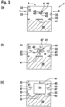
- Steps of exemplary embodiments of the method for determining the estimated real dimensions of an elevator car 7 will now be described with reference to Fig. 3 and 4 .
- a starting area 41 is defined.
- the starting area 41 forms a rectangular area 45 and shall be located within the real dimensions of the elevator car 7.
- additional information acquired from prior knowledge data may be used.
- the starting area 41 may be a single pixel of the virtual 2-dimensional map 30.
- the rectangular starting area 41 is arranged such that its edges 43 are parallel with respect to one of the walls 9 of the elevator car 7.
- the starting area 41 forming the rectangular area 45 is extended by one pixel in each of four extension directions 47. Thereby, a larger rectangular area 45 is formed and, compared to the starting area 41, the edges 43 of this larger rectangular area 45 are displaced towards the walls 9 of the elevator car 7.
- This process of extending the rectangular area 45 by one pixel in each extension direction 47 is repeated until one of the pixels extended in such manner corresponds to one of the reflection surfaces 33, i.e. the location of the pixel overlaps with the location of the reflection surface 33.
- Such situation is represented in Fig. 3(c) , where the lower edge 43 of the rectangular area 45 coincides with the reflection surface 33 created by one of the linear structures 37 representing non-mirroring wall portions, after having been extended several times in the downward extension direction 47. The extending of the rectangular area 45 in this downward extension direction 47 is then stopped.
- the rectangular area 45 is further extended in successive steps until the entire white portion 31 representing the real accessible area is completely filled-out with the rectangular area 45.
- the rectangular area 45 is fully extended to a maximum and may be taken as representing the estimated real dimensions of the elevator car 7.
- Fig. 4 shows an example in which the starting area 41 is originally not set at a suitable position. Instead, the starting area 41 is set at a position being too close to one of the mirrors 11 the elevator car 7.
- the method steps of defining the starting area 41 and then successively extending the rectangular area 45 may be repeated in several iterations. Therein, in each of the iterations, the starting area 41 may be set at another position.
- the starting area 41 may be set within the fully extended rectangular area 45 determined in the preceding first iteration. Starting at such alternative position, the rectangular area 45 may then be successively extended until the fully extended rectangular area 45 correctly fills the entire real dimensions of the elevator car 7.
Landscapes
- Engineering & Computer Science (AREA)
- Physics & Mathematics (AREA)
- Mechanical Engineering (AREA)
- Robotics (AREA)
- General Physics & Mathematics (AREA)
- Radar, Positioning & Navigation (AREA)
- Remote Sensing (AREA)
- Electromagnetism (AREA)
- Computer Networks & Wireless Communication (AREA)
- Optics & Photonics (AREA)
- Lift-Guide Devices, And Elevator Ropes And Cables (AREA)
- Length Measuring Devices By Optical Means (AREA)
- Maintenance And Inspection Apparatuses For Elevators (AREA)
- Elevator Control (AREA)
- Optical Radar Systems And Details Thereof (AREA)
- Indicating And Signalling Devices For Elevators (AREA)
Claims (14)
- Verfahren zum Erfassen geschätzter realer Abmessungen einer Aufzugskabine (7), das Verfahren umfassend folgende Schritte:(a) Aufnehmen einer virtuellen 2-dimensionalen Abbildung (30) der Aufzugskabine (7) basierend auf Daten, die durch einen Lidarsensor (17) bereitgestellt werden, wobei die virtuelle 2-dimensionale Abbildung (30) Reflexionsoberflächen (33) darstellt, von denen Laserlicht reflektiert wird, das durch den Lidarsensor (17) emittiert wird,(b) Definieren eines Startbereichs (41) als einen rechteckigen Bereich (45) an einer Position, die sich innerhalb der realen Abmessungen des Aufzugskabine (7) befindet,(c) aufeinanderfolgendes Verlängern des rechteckigen Bereichs (45) durch ein Pixel in jeder der vier Verlängerungsrichtungen (47) orthogonal zu Rändern (43) des rechteckigen Bereichs (45), einschließlich, falls ein beliebiges Pixel in einer der Verlängerungsrichtungen (47) einer der Reflexionsoberflächen (33) entspricht, die in der virtuellen 2-dimensionalen Abbildung (30) angegeben sind, Stoppen des Verlängerns des rechteckigen Bereichs (45) in dieser Verlängerungsrichtung (47) und aufeinanderfolgendes Verlängern des rechteckigen Bereichs (45) durch ein Pixel nur in jeder der verbleibenden Verlängerungsrichtungen (47), bis der rechteckige Bereich (45) zu einem Maximum in jeder der Verlängerungsrichtungen (47) vollständig verlängert wurde, und(d) Erfassen des vollständig verlängerten rechteckigen Bereichs (45) als die geschätzten realen Abmessungen der Aufzugskabine (7).
- Verfahren nach Anspruch 1,
wobei der Startbereich (41) basierend auf Vorwissensdaten definiert ist, die zusätzliche Informationen über die realen Abmessungen der Aufzugskabine (7) angeben. - Verfahren nach einem der vorstehenden Ansprüche,
wobei der Startbereich an oder nahe einer geometrischen Mitte der Aufzugskabine (7) definiert ist. - Verfahren nach einem der vorstehenden Ansprüche,
wobei der Startbereich (41) mit Rändern (43) des rechteckigen Bereichs (45) definiert ist, die parallel zu Wänden (9) der Aufzugskabine (7) sind. - Verfahren nach einem der vorstehenden Ansprüche,
wobei die Schritte (b) bis (c) in Iterationen wiederholt werden, wobei der Startbereich (41) in Schritt (b) an verschiedenen Positionen definiert wird, die sich innerhalb der realen Abmessungen der Aufzugskabine (7) befinden. - Verfahren nach Anspruch 5, wobei, in jeder der nachfolgenden Iterationen, der Startbereich (41) an einer Position definiert ist, die sich innerhalb des vollständig verlängerten rechteckigen Bereichs (45) befindet, der in einer ersten Iteration erfasst wird.
- Verfahren nach einem der Ansprüche 5 und 6, wobei, in Schritt (d), falls alle Iterationen in einem gleichen vollständig verlängerten rechteckigen Bereich (45) resultieren, der vollständig verlängerte rechteckige Bereich (45) als die geschätzten realen Abmessungen der Aufzugskabine (7) bereitgestellt wird.
- Verfahren nach einem der Ansprüche 5 und 6, wobei, in Schritt (d), falls die Iterationen zu unterschiedlichen vollständig verlängerten rechteckigen Bereichen (45) führen, Auswählen einer wahrscheinlichsten Lösung unter den unterschiedlichen vollständig verlängerten rechteckigen Bereichen unter Berücksichtigung eines zusätzlichen Vorwissens und Erfassen der wahrscheinlichsten Lösung als die geschätzten realen Abmessungen der Aufzugskabine (7).
- Verfahren nach einem der Ansprüche 5 bis 8, wobei jeder erfasste vollständig verlängerte rechteckige Bereich (45), der nicht den Startbereich (41) einschließt, der in der ersten Iteration definiert wird, beim Erfassen der geschätzten realen Abmessungen der Aufzugskabine (7) nicht beachtet wird.
- Rechenvorrichtung (29) zum Erfassen geschätzter realer Abmessungen einer Aufzugskabine (7), dadurch gekennzeichnet, dass
die Rechenvorrichtung (29) für eines von Ausführen und Steuern des Verfahrens nach einem der Ansprüche 1 bis 9 ausgestaltet ist. - Wartungsanordnung (1) zum Bereitstellen einer Unterstützung bei einem Warten einer Aufzugsanordnung (3), die Wartungsanordnung (1) umfassend:einen Abbildungsroboter (5), umfassend eine Mobilisierungseinheit (13) und einen Lidarsensor (17), wobei der Abbildungsroboter (5) zum Fahren entlang eines zugänglichen Raums in der Aufzuganordnung (3), der durch die Mobilisierungseinheit (13) angetrieben wird, und zum Aufnehmen einer virtuellen 2-dimensionalen Abbildung (30) einer Umgebung des Abbildungsroboters (5) unter Verwendung des Lidarsensors (17) ausgestaltet ist, undeine Rechenvorrichtung (29) nach Anspruch 10,wobei die Rechenvorrichtung (29) zum Erfassen geschätzter realer Abmessungen einer Aufzugskabine (7) basierend auf einer virtuellen 2-dimensionalen Abbildung (30) der Aufzugskabine (7) ausgestaltet ist, die mit dem Lidarsensor (17) des Abbildungsroboters (5) aufgenommen wird.
- Wartungsanordnung nach Anspruch 11,wobei mindestens einer von dem Abbildungsroboter (5) und einem optionalen Wartungsroboter, umfassend eine Mobilisierungseinheit, zum Ausführen eines Wartungsvorgangs innerhalb einer Aufzugskabine (7) ausgestaltet ist, undwobei der mindestens eine von dem Abbildungsroboter (5) und dem Wartungsroboter zum Bewegen innerhalb der Aufzugskabine (7) unter Berücksichtigung der erfassten geschätzten realen Abmessungen einer Aufzugskabine (7) ausgestaltet ist.
- Computerprogrammprodukt, umfassend computerlesbare Anweisungen, die einen Prozessor für eines von Ausführen und Steuern des Verfahrens nach einem der Ansprüche 1 bis 9 anweisen.
- Computerlesbares Medium, das das Computerprogrammprodukt nach Anspruch 13 darauf gespeichert aufweist.
Applications Claiming Priority (2)
| Application Number | Priority Date | Filing Date | Title |
|---|---|---|---|
| EP20155774 | 2020-02-06 | ||
| PCT/EP2021/052240 WO2021156168A1 (en) | 2020-02-06 | 2021-02-01 | Method and device for determining estimated real dimensions of an elevator car |
Publications (2)
| Publication Number | Publication Date |
|---|---|
| EP4100352A1 EP4100352A1 (de) | 2022-12-14 |
| EP4100352B1 true EP4100352B1 (de) | 2024-01-10 |
Family
ID=69500679
Family Applications (1)
| Application Number | Title | Priority Date | Filing Date |
|---|---|---|---|
| EP21702023.9A Active EP4100352B1 (de) | 2020-02-06 | 2021-02-01 | Verfahren und vorrichtung zur bestimmung von geschätzten realen abmessungen einer aufzugskabine |
Country Status (8)
| Country | Link |
|---|---|
| US (1) | US12534340B2 (de) |
| EP (1) | EP4100352B1 (de) |
| JP (1) | JP7631357B2 (de) |
| KR (1) | KR20220137654A (de) |
| CN (1) | CN115052828B (de) |
| AU (1) | AU2021217745B2 (de) |
| CA (1) | CA3169058A1 (de) |
| WO (1) | WO2021156168A1 (de) |
Families Citing this family (2)
| Publication number | Priority date | Publication date | Assignee | Title |
|---|---|---|---|---|
| CN117991288B (zh) * | 2024-04-03 | 2024-06-14 | 浙江浙能数字科技有限公司 | 基于激光雷达的车厢检测预警装置及方法 |
| KR102776633B1 (ko) | 2024-10-10 | 2025-03-06 | 아이이앤엘 주식회사 | 3d 데이터 기반 엘리베이터 설치 단계 별 검수 방법 및 이를 수행하는 전자 장치 |
Family Cites Families (18)
| Publication number | Priority date | Publication date | Assignee | Title |
|---|---|---|---|---|
| FR2779559B1 (fr) * | 1998-06-09 | 2000-07-21 | Otis Elevator Co | Procede et dispositif d'affichage d'une image virtuelle, notamment du tableau de commande d'une cabine d'ascenseur |
| JP2003066143A (ja) * | 2001-08-28 | 2003-03-05 | Toshiba Elevator Co Ltd | 昇降路内寸法測定方法およびエレベータの寸法測定装置 |
| CN1322310C (zh) * | 2005-07-14 | 2007-06-20 | 上海交通大学 | 电梯导轨横向位移测量装置 |
| JP5746438B2 (ja) * | 2012-07-24 | 2015-07-08 | 三菱電機株式会社 | エレベータの制御システム、及びエレベータの制御方法 |
| US9025861B2 (en) * | 2013-04-09 | 2015-05-05 | Google Inc. | System and method for floorplan reconstruction and three-dimensional modeling |
| CN103979373B (zh) * | 2014-05-09 | 2017-01-18 | 日立电梯(中国)有限公司 | 电梯及其显示控制方法 |
| US10081515B2 (en) * | 2014-06-09 | 2018-09-25 | Mitsubishi Electric Corporation | Method for measuring shaft and interference determination system |
| JP6480824B2 (ja) * | 2015-07-27 | 2019-03-13 | 株式会社日立製作所 | 距離画像センサのパラメータ調整方法、パラメータ調整装置、およびエレベータシステム |
| JP6545065B2 (ja) * | 2015-09-30 | 2019-07-17 | 株式会社日立ビルシステム | 3次元点群データのモデリング装置、モデリングプログラム及びエレベータガイドレールのモデリング方法 |
| JP2020510820A (ja) * | 2017-03-16 | 2020-04-09 | トリナミクス ゲゼルシャフト ミット ベシュレンクテル ハフツング | 少なくとも1つの物体を光学的に検出するための検出器 |
| JP2018159605A (ja) * | 2017-03-22 | 2018-10-11 | 株式会社日立ビルシステム | エレベーターシステムおよび内部調整パラメータ算出方法 |
| CN109969889B (zh) * | 2017-12-28 | 2024-05-10 | 三菱电机上海机电电梯有限公司 | 电梯轿厢内卫生环境监控装置 |
| CN207908967U (zh) * | 2017-12-28 | 2018-09-25 | 广州赛特智能科技有限公司 | 一种激光雷达式辅助agv使用电梯装置 |
| EP3527522B1 (de) * | 2018-02-15 | 2021-06-02 | KONE Corporation | Verfahren zur präventiven wartung eines aufzugs und eines aufzugsystems |
| CN208747405U (zh) * | 2018-07-03 | 2019-04-16 | 康姆帕斯电子科技衡水有限公司 | 基于3d视频的激光测试探头设备 |
| JP7136680B2 (ja) * | 2018-12-25 | 2022-09-13 | 株式会社日立製作所 | エレベーターシステム |
| JP7237702B2 (ja) * | 2019-04-09 | 2023-03-13 | 株式会社Ihi | 荷揚げ装置 |
| US12014120B2 (en) * | 2019-08-28 | 2024-06-18 | MFTB Holdco, Inc. | Automated tools for generating mapping information for buildings |
-
2021
- 2021-02-01 EP EP21702023.9A patent/EP4100352B1/de active Active
- 2021-02-01 CA CA3169058A patent/CA3169058A1/en active Pending
- 2021-02-01 WO PCT/EP2021/052240 patent/WO2021156168A1/en not_active Ceased
- 2021-02-01 CN CN202180013067.7A patent/CN115052828B/zh active Active
- 2021-02-01 US US17/759,521 patent/US12534340B2/en active Active
- 2021-02-01 JP JP2022547900A patent/JP7631357B2/ja active Active
- 2021-02-01 AU AU2021217745A patent/AU2021217745B2/en active Active
- 2021-02-01 KR KR1020227027284A patent/KR20220137654A/ko active Pending
Also Published As
| Publication number | Publication date |
|---|---|
| CN115052828A (zh) | 2022-09-13 |
| EP4100352A1 (de) | 2022-12-14 |
| KR20220137654A (ko) | 2022-10-12 |
| US20230089074A1 (en) | 2023-03-23 |
| WO2021156168A1 (en) | 2021-08-12 |
| JP2023513193A (ja) | 2023-03-30 |
| US12534340B2 (en) | 2026-01-27 |
| CA3169058A1 (en) | 2021-08-12 |
| AU2021217745B2 (en) | 2024-07-18 |
| JP7631357B2 (ja) | 2025-02-18 |
| CN115052828B (zh) | 2024-05-03 |
| AU2021217745A1 (en) | 2022-09-01 |
Similar Documents
| Publication | Publication Date | Title |
|---|---|---|
| US11915427B2 (en) | Conflict resolver for a lidar data segmentation system of an autonomous vehicle | |
| JP7045816B2 (ja) | 検査ステーションに配置された車両の最外寸法を測定するための方法及びシステム | |
| US8676429B2 (en) | Autonomous mobile device | |
| EP3196128A1 (de) | System und verfahren zur flugzeugandockführung und zur flugzeugtypidentifizierung | |
| AU2021217745B2 (en) | Method and device for determining estimated real dimensions of an elevator car | |
| CN107710094A (zh) | 自主车辆运行期间的在线校准检查 | |
| US20220289026A1 (en) | Object Detection Sensor Alignment | |
| US11449067B1 (en) | Conflict resolver for a lidar data segmentation system of an autonomous vehicle | |
| US11619725B1 (en) | Method and device for the recognition of blooming in a lidar measurement | |
| CN113490973B (zh) | 信息处理装置以及移动机器人 | |
| CN112581771A (zh) | 自动驾驶车辆用的驾驶控制装置、停车用物标、驾驶控制系统 | |
| JP2022124865A (ja) | 移動体、移動制御システム、移動体の制御方法及びプログラム | |
| US20190293793A1 (en) | Position recognizing device | |
| US20230128651A1 (en) | Determining scanner error | |
| HK40074206A (en) | Method and device for determining estimated real dimensions of an elevator car | |
| HK40074206B (zh) | 用於确定电梯轿厢的估计的实际尺寸的方法和设备 | |
| US12391527B2 (en) | Load transport system, method of load transport system, and non-transitory computer-readable recording medium | |
| US20250224732A1 (en) | Method for determining point groups which are visible or not visible from a specified viewing point | |
| US20230251350A1 (en) | Information processing device, information processing method, and information processing program | |
| JP2024042454A (ja) | 経路設定方法、プログラム及び移動体 | |
| US20240095932A1 (en) | Method, non-transitory computer readable storage medium, training data set, and device for connecting point cloud data with related data | |
| JP7819393B2 (ja) | 情報処理装置、方法、プログラム及び記憶媒体 | |
| JP2025066569A (ja) | 物体配置推定システム、物体配置推定装置、物体配置推定方法、及び、プログラム | |
| WO2025134956A1 (ja) | 電磁波照射装置 | |
| KR20250056628A (ko) | 포인트 클라우드의 음영 지역을 이용한 객체 검출 방법 및 장치 |
Legal Events
| Date | Code | Title | Description |
|---|---|---|---|
| STAA | Information on the status of an ep patent application or granted ep patent |
Free format text: STATUS: UNKNOWN |
|
| STAA | Information on the status of an ep patent application or granted ep patent |
Free format text: STATUS: THE INTERNATIONAL PUBLICATION HAS BEEN MADE |
|
| PUAI | Public reference made under article 153(3) epc to a published international application that has entered the european phase |
Free format text: ORIGINAL CODE: 0009012 |
|
| STAA | Information on the status of an ep patent application or granted ep patent |
Free format text: STATUS: REQUEST FOR EXAMINATION WAS MADE |
|
| 17P | Request for examination filed |
Effective date: 20220705 |
|
| AK | Designated contracting states |
Kind code of ref document: A1 Designated state(s): AL AT BE BG CH CY CZ DE DK EE ES FI FR GB GR HR HU IE IS IT LI LT LU LV MC MK MT NL NO PL PT RO RS SE SI SK SM TR |
|
| DAV | Request for validation of the european patent (deleted) | ||
| DAX | Request for extension of the european patent (deleted) | ||
| GRAP | Despatch of communication of intention to grant a patent |
Free format text: ORIGINAL CODE: EPIDOSNIGR1 |
|
| STAA | Information on the status of an ep patent application or granted ep patent |
Free format text: STATUS: GRANT OF PATENT IS INTENDED |
|
| INTG | Intention to grant announced |
Effective date: 20230918 |
|
| GRAS | Grant fee paid |
Free format text: ORIGINAL CODE: EPIDOSNIGR3 |
|
| GRAA | (expected) grant |
Free format text: ORIGINAL CODE: 0009210 |
|
| STAA | Information on the status of an ep patent application or granted ep patent |
Free format text: STATUS: THE PATENT HAS BEEN GRANTED |
|
| AK | Designated contracting states |
Kind code of ref document: B1 Designated state(s): AL AT BE BG CH CY CZ DE DK EE ES FI FR GB GR HR HU IE IS IT LI LT LU LV MC MK MT NL NO PL PT RO RS SE SI SK SM TR |
|
| REG | Reference to a national code |
Ref country code: GB Ref legal event code: FG4D |
|
| REG | Reference to a national code |
Ref country code: CH Ref legal event code: EP |
|
| REG | Reference to a national code |
Ref country code: DE Ref legal event code: R096 Ref document number: 602021008526 Country of ref document: DE |
|
| REG | Reference to a national code |
Ref country code: IE Ref legal event code: FG4D |
|
| REG | Reference to a national code |
Ref country code: LT Ref legal event code: MG9D |
|
| REG | Reference to a national code |
Ref country code: NL Ref legal event code: MP Effective date: 20240110 |
|
| REG | Reference to a national code |
Ref country code: AT Ref legal event code: MK05 Ref document number: 1648773 Country of ref document: AT Kind code of ref document: T Effective date: 20240110 |
|
| PG25 | Lapsed in a contracting state [announced via postgrant information from national office to epo] |
Ref country code: NL Free format text: LAPSE BECAUSE OF FAILURE TO SUBMIT A TRANSLATION OF THE DESCRIPTION OR TO PAY THE FEE WITHIN THE PRESCRIBED TIME-LIMIT Effective date: 20240110 |
|
| PG25 | Lapsed in a contracting state [announced via postgrant information from national office to epo] |
Ref country code: NL Free format text: LAPSE BECAUSE OF FAILURE TO SUBMIT A TRANSLATION OF THE DESCRIPTION OR TO PAY THE FEE WITHIN THE PRESCRIBED TIME-LIMIT Effective date: 20240110 |
|
| PG25 | Lapsed in a contracting state [announced via postgrant information from national office to epo] |
Ref country code: IS Free format text: LAPSE BECAUSE OF FAILURE TO SUBMIT A TRANSLATION OF THE DESCRIPTION OR TO PAY THE FEE WITHIN THE PRESCRIBED TIME-LIMIT Effective date: 20240510 |
|
| PG25 | Lapsed in a contracting state [announced via postgrant information from national office to epo] |
Ref country code: LT Free format text: LAPSE BECAUSE OF FAILURE TO SUBMIT A TRANSLATION OF THE DESCRIPTION OR TO PAY THE FEE WITHIN THE PRESCRIBED TIME-LIMIT Effective date: 20240110 |
|
| PG25 | Lapsed in a contracting state [announced via postgrant information from national office to epo] |
Ref country code: GR Free format text: LAPSE BECAUSE OF FAILURE TO SUBMIT A TRANSLATION OF THE DESCRIPTION OR TO PAY THE FEE WITHIN THE PRESCRIBED TIME-LIMIT Effective date: 20240411 |
|
| PG25 | Lapsed in a contracting state [announced via postgrant information from national office to epo] |
Ref country code: RS Free format text: LAPSE BECAUSE OF FAILURE TO SUBMIT A TRANSLATION OF THE DESCRIPTION OR TO PAY THE FEE WITHIN THE PRESCRIBED TIME-LIMIT Effective date: 20240410 Ref country code: HR Free format text: LAPSE BECAUSE OF FAILURE TO SUBMIT A TRANSLATION OF THE DESCRIPTION OR TO PAY THE FEE WITHIN THE PRESCRIBED TIME-LIMIT Effective date: 20240110 |
|
| PG25 | Lapsed in a contracting state [announced via postgrant information from national office to epo] |
Ref country code: ES Free format text: LAPSE BECAUSE OF FAILURE TO SUBMIT A TRANSLATION OF THE DESCRIPTION OR TO PAY THE FEE WITHIN THE PRESCRIBED TIME-LIMIT Effective date: 20240110 |
|
| PG25 | Lapsed in a contracting state [announced via postgrant information from national office to epo] |
Ref country code: AT Free format text: LAPSE BECAUSE OF FAILURE TO SUBMIT A TRANSLATION OF THE DESCRIPTION OR TO PAY THE FEE WITHIN THE PRESCRIBED TIME-LIMIT Effective date: 20240110 |
|
| PG25 | Lapsed in a contracting state [announced via postgrant information from national office to epo] |
Ref country code: RS Free format text: LAPSE BECAUSE OF FAILURE TO SUBMIT A TRANSLATION OF THE DESCRIPTION OR TO PAY THE FEE WITHIN THE PRESCRIBED TIME-LIMIT Effective date: 20240410 Ref country code: NO Free format text: LAPSE BECAUSE OF FAILURE TO SUBMIT A TRANSLATION OF THE DESCRIPTION OR TO PAY THE FEE WITHIN THE PRESCRIBED TIME-LIMIT Effective date: 20240410 Ref country code: LT Free format text: LAPSE BECAUSE OF FAILURE TO SUBMIT A TRANSLATION OF THE DESCRIPTION OR TO PAY THE FEE WITHIN THE PRESCRIBED TIME-LIMIT Effective date: 20240110 Ref country code: IS Free format text: LAPSE BECAUSE OF FAILURE TO SUBMIT A TRANSLATION OF THE DESCRIPTION OR TO PAY THE FEE WITHIN THE PRESCRIBED TIME-LIMIT Effective date: 20240510 Ref country code: HR Free format text: LAPSE BECAUSE OF FAILURE TO SUBMIT A TRANSLATION OF THE DESCRIPTION OR TO PAY THE FEE WITHIN THE PRESCRIBED TIME-LIMIT Effective date: 20240110 Ref country code: GR Free format text: LAPSE BECAUSE OF FAILURE TO SUBMIT A TRANSLATION OF THE DESCRIPTION OR TO PAY THE FEE WITHIN THE PRESCRIBED TIME-LIMIT Effective date: 20240411 Ref country code: ES Free format text: LAPSE BECAUSE OF FAILURE TO SUBMIT A TRANSLATION OF THE DESCRIPTION OR TO PAY THE FEE WITHIN THE PRESCRIBED TIME-LIMIT Effective date: 20240110 Ref country code: BG Free format text: LAPSE BECAUSE OF FAILURE TO SUBMIT A TRANSLATION OF THE DESCRIPTION OR TO PAY THE FEE WITHIN THE PRESCRIBED TIME-LIMIT Effective date: 20240110 Ref country code: AT Free format text: LAPSE BECAUSE OF FAILURE TO SUBMIT A TRANSLATION OF THE DESCRIPTION OR TO PAY THE FEE WITHIN THE PRESCRIBED TIME-LIMIT Effective date: 20240110 |
|
| PG25 | Lapsed in a contracting state [announced via postgrant information from national office to epo] |
Ref country code: PL Free format text: LAPSE BECAUSE OF FAILURE TO SUBMIT A TRANSLATION OF THE DESCRIPTION OR TO PAY THE FEE WITHIN THE PRESCRIBED TIME-LIMIT Effective date: 20240110 Ref country code: PT Free format text: LAPSE BECAUSE OF FAILURE TO SUBMIT A TRANSLATION OF THE DESCRIPTION OR TO PAY THE FEE WITHIN THE PRESCRIBED TIME-LIMIT Effective date: 20240510 |
|
| PG25 | Lapsed in a contracting state [announced via postgrant information from national office to epo] |
Ref country code: SE Free format text: LAPSE BECAUSE OF FAILURE TO SUBMIT A TRANSLATION OF THE DESCRIPTION OR TO PAY THE FEE WITHIN THE PRESCRIBED TIME-LIMIT Effective date: 20240110 Ref country code: PT Free format text: LAPSE BECAUSE OF FAILURE TO SUBMIT A TRANSLATION OF THE DESCRIPTION OR TO PAY THE FEE WITHIN THE PRESCRIBED TIME-LIMIT Effective date: 20240510 Ref country code: PL Free format text: LAPSE BECAUSE OF FAILURE TO SUBMIT A TRANSLATION OF THE DESCRIPTION OR TO PAY THE FEE WITHIN THE PRESCRIBED TIME-LIMIT Effective date: 20240110 Ref country code: LV Free format text: LAPSE BECAUSE OF FAILURE TO SUBMIT A TRANSLATION OF THE DESCRIPTION OR TO PAY THE FEE WITHIN THE PRESCRIBED TIME-LIMIT Effective date: 20240110 |
|
| PG25 | Lapsed in a contracting state [announced via postgrant information from national office to epo] |
Ref country code: DK Free format text: LAPSE BECAUSE OF FAILURE TO SUBMIT A TRANSLATION OF THE DESCRIPTION OR TO PAY THE FEE WITHIN THE PRESCRIBED TIME-LIMIT Effective date: 20240110 |
|
| REG | Reference to a national code |
Ref country code: DE Ref legal event code: R097 Ref document number: 602021008526 Country of ref document: DE |
|
| PG25 | Lapsed in a contracting state [announced via postgrant information from national office to epo] |
Ref country code: SM Free format text: LAPSE BECAUSE OF FAILURE TO SUBMIT A TRANSLATION OF THE DESCRIPTION OR TO PAY THE FEE WITHIN THE PRESCRIBED TIME-LIMIT Effective date: 20240110 |
|
| PG25 | Lapsed in a contracting state [announced via postgrant information from national office to epo] |
Ref country code: LU Free format text: LAPSE BECAUSE OF NON-PAYMENT OF DUE FEES Effective date: 20240201 |
|
| PG25 | Lapsed in a contracting state [announced via postgrant information from national office to epo] |
Ref country code: EE Free format text: LAPSE BECAUSE OF FAILURE TO SUBMIT A TRANSLATION OF THE DESCRIPTION OR TO PAY THE FEE WITHIN THE PRESCRIBED TIME-LIMIT Effective date: 20240110 Ref country code: CZ Free format text: LAPSE BECAUSE OF FAILURE TO SUBMIT A TRANSLATION OF THE DESCRIPTION OR TO PAY THE FEE WITHIN THE PRESCRIBED TIME-LIMIT Effective date: 20240110 |
|
| PG25 | Lapsed in a contracting state [announced via postgrant information from national office to epo] |
Ref country code: SK Free format text: LAPSE BECAUSE OF FAILURE TO SUBMIT A TRANSLATION OF THE DESCRIPTION OR TO PAY THE FEE WITHIN THE PRESCRIBED TIME-LIMIT Effective date: 20240110 |
|
| PG25 | Lapsed in a contracting state [announced via postgrant information from national office to epo] |
Ref country code: SM Free format text: LAPSE BECAUSE OF FAILURE TO SUBMIT A TRANSLATION OF THE DESCRIPTION OR TO PAY THE FEE WITHIN THE PRESCRIBED TIME-LIMIT Effective date: 20240110 Ref country code: SK Free format text: LAPSE BECAUSE OF FAILURE TO SUBMIT A TRANSLATION OF THE DESCRIPTION OR TO PAY THE FEE WITHIN THE PRESCRIBED TIME-LIMIT Effective date: 20240110 Ref country code: RO Free format text: LAPSE BECAUSE OF FAILURE TO SUBMIT A TRANSLATION OF THE DESCRIPTION OR TO PAY THE FEE WITHIN THE PRESCRIBED TIME-LIMIT Effective date: 20240110 Ref country code: LU Free format text: LAPSE BECAUSE OF NON-PAYMENT OF DUE FEES Effective date: 20240201 Ref country code: EE Free format text: LAPSE BECAUSE OF FAILURE TO SUBMIT A TRANSLATION OF THE DESCRIPTION OR TO PAY THE FEE WITHIN THE PRESCRIBED TIME-LIMIT Effective date: 20240110 Ref country code: DK Free format text: LAPSE BECAUSE OF FAILURE TO SUBMIT A TRANSLATION OF THE DESCRIPTION OR TO PAY THE FEE WITHIN THE PRESCRIBED TIME-LIMIT Effective date: 20240110 Ref country code: CZ Free format text: LAPSE BECAUSE OF FAILURE TO SUBMIT A TRANSLATION OF THE DESCRIPTION OR TO PAY THE FEE WITHIN THE PRESCRIBED TIME-LIMIT Effective date: 20240110 |
|
| PG25 | Lapsed in a contracting state [announced via postgrant information from national office to epo] |
Ref country code: MC Free format text: LAPSE BECAUSE OF FAILURE TO SUBMIT A TRANSLATION OF THE DESCRIPTION OR TO PAY THE FEE WITHIN THE PRESCRIBED TIME-LIMIT Effective date: 20240110 |
|
| PLBE | No opposition filed within time limit |
Free format text: ORIGINAL CODE: 0009261 |
|
| STAA | Information on the status of an ep patent application or granted ep patent |
Free format text: STATUS: NO OPPOSITION FILED WITHIN TIME LIMIT |
|
| PG25 | Lapsed in a contracting state [announced via postgrant information from national office to epo] |
Ref country code: MC Free format text: LAPSE BECAUSE OF FAILURE TO SUBMIT A TRANSLATION OF THE DESCRIPTION OR TO PAY THE FEE WITHIN THE PRESCRIBED TIME-LIMIT Effective date: 20240110 |
|
| PG25 | Lapsed in a contracting state [announced via postgrant information from national office to epo] |
Ref country code: IT Free format text: LAPSE BECAUSE OF FAILURE TO SUBMIT A TRANSLATION OF THE DESCRIPTION OR TO PAY THE FEE WITHIN THE PRESCRIBED TIME-LIMIT Effective date: 20240110 |
|
| REG | Reference to a national code |
Ref country code: BE Ref legal event code: MM Effective date: 20240229 |
|
| 26N | No opposition filed |
Effective date: 20241011 |
|
| PG25 | Lapsed in a contracting state [announced via postgrant information from national office to epo] |
Ref country code: IT Free format text: LAPSE BECAUSE OF FAILURE TO SUBMIT A TRANSLATION OF THE DESCRIPTION OR TO PAY THE FEE WITHIN THE PRESCRIBED TIME-LIMIT Effective date: 20240110 |
|
| PG25 | Lapsed in a contracting state [announced via postgrant information from national office to epo] |
Ref country code: BE Free format text: LAPSE BECAUSE OF NON-PAYMENT OF DUE FEES Effective date: 20240229 |
|
| PG25 | Lapsed in a contracting state [announced via postgrant information from national office to epo] |
Ref country code: IE Free format text: LAPSE BECAUSE OF NON-PAYMENT OF DUE FEES Effective date: 20240201 |
|
| PG25 | Lapsed in a contracting state [announced via postgrant information from national office to epo] |
Ref country code: IE Free format text: LAPSE BECAUSE OF NON-PAYMENT OF DUE FEES Effective date: 20240201 Ref country code: BE Free format text: LAPSE BECAUSE OF NON-PAYMENT OF DUE FEES Effective date: 20240229 |
|
| PG25 | Lapsed in a contracting state [announced via postgrant information from national office to epo] |
Ref country code: SI Free format text: LAPSE BECAUSE OF FAILURE TO SUBMIT A TRANSLATION OF THE DESCRIPTION OR TO PAY THE FEE WITHIN THE PRESCRIBED TIME-LIMIT Effective date: 20240110 |
|
| PG25 | Lapsed in a contracting state [announced via postgrant information from national office to epo] |
Ref country code: CY Free format text: LAPSE BECAUSE OF FAILURE TO SUBMIT A TRANSLATION OF THE DESCRIPTION OR TO PAY THE FEE WITHIN THE PRESCRIBED TIME-LIMIT; INVALID AB INITIO Effective date: 20210201 |
|
| PG25 | Lapsed in a contracting state [announced via postgrant information from national office to epo] |
Ref country code: HU Free format text: LAPSE BECAUSE OF FAILURE TO SUBMIT A TRANSLATION OF THE DESCRIPTION OR TO PAY THE FEE WITHIN THE PRESCRIBED TIME-LIMIT; INVALID AB INITIO Effective date: 20210201 |
|
| PG25 | Lapsed in a contracting state [announced via postgrant information from national office to epo] |
Ref country code: FI Free format text: LAPSE BECAUSE OF FAILURE TO SUBMIT A TRANSLATION OF THE DESCRIPTION OR TO PAY THE FEE WITHIN THE PRESCRIBED TIME-LIMIT Effective date: 20240110 |
|
| PG25 | Lapsed in a contracting state [announced via postgrant information from national office to epo] |
Ref country code: TR Free format text: LAPSE BECAUSE OF FAILURE TO SUBMIT A TRANSLATION OF THE DESCRIPTION OR TO PAY THE FEE WITHIN THE PRESCRIBED TIME-LIMIT Effective date: 20240110 |
|
| REG | Reference to a national code |
Ref country code: CH Ref legal event code: U11 Free format text: ST27 STATUS EVENT CODE: U-0-0-U10-U11 (AS PROVIDED BY THE NATIONAL OFFICE) Effective date: 20260301 |
|
| PGFP | Annual fee paid to national office [announced via postgrant information from national office to epo] |
Ref country code: GB Payment date: 20260223 Year of fee payment: 6 |
|
| PGFP | Annual fee paid to national office [announced via postgrant information from national office to epo] |
Ref country code: DE Payment date: 20260226 Year of fee payment: 6 |
|
| PGFP | Annual fee paid to national office [announced via postgrant information from national office to epo] |
Ref country code: FR Payment date: 20260224 Year of fee payment: 6 |
|
| PGFP | Annual fee paid to national office [announced via postgrant information from national office to epo] |
Ref country code: CH Payment date: 20260301 Year of fee payment: 6 |