EP4100283B1 - Bouclier avant de véhicule automobile équipé d'un radar et structure avant de véhicule comprenant un tel bouclier - Google Patents
Bouclier avant de véhicule automobile équipé d'un radar et structure avant de véhicule comprenant un tel bouclier Download PDFInfo
- Publication number
- EP4100283B1 EP4100283B1 EP21701985.0A EP21701985A EP4100283B1 EP 4100283 B1 EP4100283 B1 EP 4100283B1 EP 21701985 A EP21701985 A EP 21701985A EP 4100283 B1 EP4100283 B1 EP 4100283B1
- Authority
- EP
- European Patent Office
- Prior art keywords
- protective moulding
- moulding
- protective
- impact absorbing
- vehicle
- Prior art date
- Legal status (The legal status is an assumption and is not a legal conclusion. Google has not performed a legal analysis and makes no representation as to the accuracy of the status listed.)
- Active
Links
Images


Classifications
-
- B—PERFORMING OPERATIONS; TRANSPORTING
- B60—VEHICLES IN GENERAL
- B60R—VEHICLES, VEHICLE FITTINGS, OR VEHICLE PARTS, NOT OTHERWISE PROVIDED FOR
- B60R19/00—Wheel guards; Radiator guards, e.g. grilles; Obstruction removers; Fittings damping bouncing force in collisions
- B60R19/02—Bumpers, i.e. impact receiving or absorbing members for protecting vehicles or fending off blows from other vehicles or objects
- B60R19/48—Bumpers, i.e. impact receiving or absorbing members for protecting vehicles or fending off blows from other vehicles or objects combined with, or convertible into, other devices or objects, e.g. bumpers combined with road brushes, bumpers convertible into beds
- B60R19/483—Bumpers, i.e. impact receiving or absorbing members for protecting vehicles or fending off blows from other vehicles or objects combined with, or convertible into, other devices or objects, e.g. bumpers combined with road brushes, bumpers convertible into beds with obstacle sensors of electric or electronic type
-
- B—PERFORMING OPERATIONS; TRANSPORTING
- B60—VEHICLES IN GENERAL
- B60R—VEHICLES, VEHICLE FITTINGS, OR VEHICLE PARTS, NOT OTHERWISE PROVIDED FOR
- B60R19/00—Wheel guards; Radiator guards, e.g. grilles; Obstruction removers; Fittings damping bouncing force in collisions
- B60R19/02—Bumpers, i.e. impact receiving or absorbing members for protecting vehicles or fending off blows from other vehicles or objects
- B60R19/18—Bumpers, i.e. impact receiving or absorbing members for protecting vehicles or fending off blows from other vehicles or objects characterised by the cross-section; Means within the bumper to absorb impact
- B60R2019/186—Additional energy absorbing means supported on bumber beams, e.g. cellular structures or material
-
- B—PERFORMING OPERATIONS; TRANSPORTING
- B60—VEHICLES IN GENERAL
- B60R—VEHICLES, VEHICLE FITTINGS, OR VEHICLE PARTS, NOT OTHERWISE PROVIDED FOR
- B60R19/00—Wheel guards; Radiator guards, e.g. grilles; Obstruction removers; Fittings damping bouncing force in collisions
- B60R19/02—Bumpers, i.e. impact receiving or absorbing members for protecting vehicles or fending off blows from other vehicles or objects
- B60R19/18—Bumpers, i.e. impact receiving or absorbing members for protecting vehicles or fending off blows from other vehicles or objects characterised by the cross-section; Means within the bumper to absorb impact
- B60R2019/1886—Bumper fascias and fastening means therefor
Definitions
- the subject of the invention is a front shield of a motor vehicle equipped with a radar as well as a front structure of a vehicle comprising such a shield.
- AEBS radar Advanced Energy Braking System
- ECE42 European regulation ECE42
- this radar can be found in front of the rigid impactor launched at 4km/h provided for in the ECE42 regulations in the case of these small front impacts, in particular when this impactor is positioned in front of the center of the vehicle following the width of this last.
- the invention proposes a front shield of a motor vehicle with the characteristics of claim 1.
- the radar support is located partly in front of the shock absorber in the longitudinal direction and partly below the latter vertically.
- the shock absorber element has two shock absorption stops located on either side of the radar support in the transverse direction, these stops being integral with a lower face of the shock absorber element. shock. This lower face is particularly directed towards the ground when the shield is mounted on the vehicle. It can be parallel or substantially parallel to the transverse and longitudinal directions.
- the shock absorption stops will receive and absorb a front shock on either side of the radar support. Furthermore, the radar support being located in front and then below the shock absorbing element, and in particular at least partly between the stops, a deformation of these elements during a longitudinal front impact will not cause contact between the stops. and radar support, which helps preserve radar support.
- the stops can be arranged symmetrically on either side of the radar support, the latter being located in the center of the shield in the transverse direction.
- the invention also relates to a front structure of a motor vehicle comprising a front shield according to the invention and a front cross member for supporting the shield, the shock absorbing element extending along the front cross member, facing it following a longitudinal direction of the vehicle when the front structure is mounted on the vehicle.
- This arrangement makes it possible to prevent the stops from pivoting relative to the front crossmember during a frontal impact.
- this can be obtained by a position of the stops projecting relative to the shock absorbing element at least in the longitudinal direction of the vehicle, possibly also in the vertical direction of the vehicle, towards the rear of the vehicle and the ground respectively.
- the invention finally relates to a motor vehicle comprising a shield according to the invention or a front structure according to the invention.
- front, rear, upper, lower refer to the front and rear, upper and lower directions of the vehicle, when the front structure and the front shield are mounted on the vehicle.
- the X, Y, Z axes correspond respectively to the longitudinal (front to back), transverse and vertical axis of the vehicle, the latter resting on the ground.
- the vertical direction thus corresponds to the direction of gravity.
- substantially horizontal, longitudinal or vertical we mean an element of which one or more parts defining a direction or a plane form an angle of at most ⁇ 20°, or even at most 10° or at most 5°, with a horizontal, longitudinal or vertical direction/plane.
- substantially parallel or perpendicular we mean an element of which one or more parts defining a direction or a plane forming an angle deviating by at most ⁇ 20°, or even by at most 10° or by at most 5° d 'a direction or a plane parallel or perpendicular.
- FIG. 1 represents a front shield 10 seen from its internal face 10a, the front shield 10 also having an external face 10b visible from outside the vehicle.
- the front shield 10 comprises a shield skin 12, a shock absorber element 14 extending in the transverse direction Y and fixed to the shield skin 12 on the side of the internal face 10a of the shield and a radar support 16 located at the 'front and extending below the shock absorber element 14 and fixed to the internal face 10a of the shield.
- the radar support 16 supports a radar 18, for example an AEBS radar.
- the radar support 16 is here located at the center or near the center of the shield in the transverse direction Y.
- the shock absorber element 14 has two shock absorption stops 141, 142 located on either side of the radar support 16 in the transverse direction. These stops, otherwise called “stoppers” are integral with a lower face 143 of the shock absorber element, located on the side of the radar support. This lower face 143 extends substantially in the plane of the X and Y directions of the vehicle. In other words, the stops 141, 142 project from the shock absorber element 14 vertically towards the ground.
- the stops can be arranged symmetrically on either side of the radar support 16, for better distribution of shock absorption.
- the stops could advantageously be arranged as close as possible to the radar support in the transverse direction, without however there being a Y-shaped overlap between the stops and the radar support in order to prevent the stops from coming into contact with the radar support during an X-shaped impact.
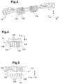
- each stop 141, 142 projects from a vertical face 144 of the shock absorber element 14 located on a side opposite the shield skin, in other words, this vertical face 144 is directed towards the rear of the vehicle ( see figure 8 ).
- Each stop can thus protrude from the shock absorbing element 14 by a predetermined distance in the longitudinal direction towards the rear of the vehicle. This allows in particular cooperation of each stop with an extreme front crosspiece as described below.
- the shock absorber element 14 can advantageously be made of polymer material, in particular the polymer materials usually used to produce shock absorption elements.
- each stop 141, 142 is made in one piece with the shock absorber element 14, for example by molding a polymer material.
- each stop 141, 142 comprises walls 145 defining ribs extending vertically and perpendicular to the transverse direction and walls 146, 147 defining a housing receiving the ribs and secured to vertical or substantially vertical edges of the ribs.
- Wall 147 is here an extension of a wall of the shock absorber element. The walls 146, 147 thus completely surround the ribs in the example, over at least part of their height (for the wall 147) or over their entire height (for the wall 146), this height being measured vertically.
- These walls 146, 147 here form a housing of generally trapezoidal shape. The invention is however not limited to this shape and a box in the shape of a parallelepiped or the like is possible.
- the housing is open on the side of a lower face opposite the shock absorber element, in other words towards the ground, thus facilitating the production of each of the stops by molding (see Figure 7 ).
- the invention is however not limited to a number of ribs, to the dimensions of the stops, nor to their shape, provided that they allow shock absorption on either side of the radar support.
- the dimensions, shapes and numbers of ribs can be determined by those skilled in the art through simulations for optimal absorption of an X-shaped shock.
- the front shield 10 has a lower part formed by the shield skin 12 and an upper part 13 forming a reinforcement, as visible more clearly figure 2 .
- the shock absorber element 14 is fixed to the shield skin 12, near the upper part 13.
- the radar support 16 is fixed to the lower part 12 and to the part upper 13 of the shield. The invention is, however, not limited to a particular number of parts of the shield.
- the radar support 14 can have at least one upper fixing element 162 and at least one lower fixing element, two, 163, 164, in the example shown.
- the at least one upper fixing element 162 is fixed to the lower part 12 and to the upper part 13 of the shield and the lower fixing elements 163, 164 are fixed only to the lower part 12. This can make it possible to improve the rigidity of the fixings, particularly at the junction of the lower and upper parts of the shield, which is located in an area generally most forward of the shield in X and therefore more deformed in the event of shock.
- the at least one upper fixing element 62 is fixed to the shield skin above the shock absorber element and the at least one lower fixing element is fixed to the bottom of the absorber element of choc.
- the shock absorber element thus extends partly in front of the shock absorber element in X.
- the shock absorber element may present, facing the radar support in the longitudinal direction, a face flat or substantially flat (face perpendicular or substantially perpendicular to the longitudinal direction) and/or a reduced dimension in X. This can further limit the risks of damage to the radar support during an impact.
- the upper fixing element 162 here forms a pierced plate for its attachment to the shield skin 12 and to the upper part 13.
- the lower fixing elements 163, 164 form vertical or substantially vertical pierced lugs, located substantially in the extension of a frame 161 for receiving and fixing the radar 18.
- the latter is here located between the upper 162 and lower fixing elements 163, 164 (see figure 2 ).
- the use of a support having a receiving and fixing part in the form of a frame makes it possible to produce a support having a certain flexibility, which favors its plastic deformation during a small impact and its return to place after the impact. It is however possible to envisage a receiving and fixing part in the form of a plate or the like, although this is not preferred.
- the radar support is made of polymer material, for example ethylene/propylene copolymer, optionally loaded with talc or the like for greater plasticity.
- each lower part 12 and upper 13 of the shield finally has openings 12a, 13a and 13b respectively (see figure 2 ) receiving visible grids 12b, 12c, 13b and 13c figure 1 .
- the presence of grilles is usual and the invention will not be limited by the number and arrangement of the openings and grilles.
- the shield skin 12 and the upper part of the shield 13 are also made of polymer material.
- the front shield 10 described is part of a front structure 20 of a motor vehicle shown figures 7 And 8 .
- This front structure 20 has a front crossmember 22 extending in the transverse direction of the vehicle.
- This front cross member 22 usually forms an extreme front cross member of the vehicle.
- the shock absorber element 14 extends along the front crossmember 22, on the front side thereof and facing the front crossmember 22 in the longitudinal direction X of the vehicle.
- the shock absorbing element 14 is located in the immediate vicinity of the front cross member 22 in -this, which prevents it from moving back further. From then on, the shock absorber element 14 as well as the stops 141, 142 will deform and absorb the shock. The presence of the stops makes it possible to limit the deformation of the elements located between them, here the radar support.
- each stop 141, 142 has an overlap distance D1 in X with the front crosspiece 22 and each stop has an overlap distance D2 in Z with the front crosspiece 22 ( fig. 8 ).
- This particular arrangement makes it possible to avoid rotation of the stops relative to the front crosspiece 22 in the event of an impact, in particular when the lower face 143 of the shock absorbing element 14 (from which the stops project) is located opposite the the crosspiece 22 in the longitudinal direction X, as shown figure 8 .
- the absence of pivoting of the stops will improve the absorption of shock by the stops in the X direction, for better protection of the radar support.
- D1 and D2 overlaps of 10 mm or more are sufficient to prevent the stops from pivoting in the event of a slight impact.
- each stop 141, 142 it would then be sufficient for each stop 141, 142 to be located opposite the front crosspiece 22 over at least part of its length measured in the longitudinal direction X to avoid pivoting of the stops in the event of an impact.
- the important thing to avoid the pivoting of the stops is in fact that in cross section, the stops 141, 142 and the shock absorbing element define an L shape such as that of the figure 8 , this L shape being opposite a corner of the front crosspiece 22.
- a D1 X overlap of 10 mm or more is sufficient to prevent rotation of the stops and improve the shock absorption behavior of the X stops.
- THE figures 6 and 7 show the deformation of the shield resulting from the maximum intrusion of an impactor 30 complying with ECE42 regulations.
- the stops 141, 142 are partly crushed against the front crosspiece 22 without having pivoted.
- the radar support 16 is inclined but intact despite the deformation of the lower part of the shield thanks to the damping provided by the stops.
- the invention thus makes it possible to obtain in a simple manner effective protection of a radar support during a weak X-ray shock.
Landscapes
- Engineering & Computer Science (AREA)
- Mechanical Engineering (AREA)
- Vibration Dampers (AREA)
- Radar Systems Or Details Thereof (AREA)
- Body Structure For Vehicles (AREA)
Description
- L'invention a pour objet un bouclier avant de véhicule automobile équipé d'un radar ainsi qu'une structure avant de véhicule comprenant un tel bouclier.
- Avec l'évolution et la généralisation des systèmes d'aide à la conduite embarqués, de plus en plus de véhicules sont équipés d'un radar destiné à la régulation de la vitesse du véhicule en fonction de distances de sécurité avec l'environnement extérieur. Ce type de radar, appelé « radar AEBS » (Advanced Energy Braking System - Système de freinage énergétique avancé) est généralement implanté en face avant du véhicule. Il est ainsi devenu nécessaire d'assurer une intégrité optimale de ces systèmes, notamment dans les cas des petits chocs avant aussi appelés « chocs parking » soumis à la réglementation européenne ECE42. Hors, ce radar peut se retrouver en face de l'impacteur rigide lancé à 4km/h prévu dans la règlementation ECE42 dans le cas de ces petits chocs avant, notamment lorsque cet impacteur est positionné en face du centre du véhicule suivant la largeur de ce dernier. Les documents
EP 2 165 890 A1 ,DE 10 2018 004377 A1 décrivent des boucliers avant de véhicules automobiles comprenant une peau de bouclier et un élément absorbeur de choc. Le documentWO 2019/043262 A1 décrit les mêmes moyens ainsi qu'un support de radar, correspondant ainsi au préambule de la revendication 1. - Il convient ainsi de limiter au maximum les intrusions des impacteurs lors de petits chocs avant, notamment de type ECE42, afin de préserver un radar AEBS implanté en face avant, en particulier lorsque le radar est fixé au bouclier et dépourvu de capot de protection.
- A cet effet, l'invention propose un bouclier avant de véhicule automobile avec les caractéristiques de la revendication 1.
- Ainsi, le support de radar est situé en partie en avant de l'absorbeur de choc suivant la direction longitudinale et en partie en dessous de ce dernier verticalement.
- Selon l'invention, l'élément absorbeur de choc présente deux butées d'absorption de choc situées de part et d'autre du support de radar suivant la direction transversale, ces butées étant solidaires d'une face inférieure de l'élément absorbeur de choc. Cette face inférieure est notamment dirigée vers le sol lorsque le bouclier est monté sur le véhicule. Elle peut être parallèle ou sensiblement parallèle aux directions transversale et longitudinale.
- Par cet agencement, les butées d'absorption de choc vont recevoir et absorber un choc avant de part et d'autre du support de radar. Par ailleurs, le support radar étant situé devant puis dessous l'élément absorbeur de choc, et en particulier au moins en partie entre les butées, une déformation de ces éléments lors d'un choc avant longitudinal n'engendrera pas un contact entre les butées et le support radar, ce qui permet de préserver le support radar.
- Avantageusement, les butées peuvent être disposées symétriquement de part et d'autre du support radar, celui-ci étant situé au centre du bouclier suivant la direction transversale.
- Le bouclier avant peut présenter une ou plusieurs des caractéristiques suivantes :
- les butées font saillie d'une face verticale de l'élément absorbeur de choc située d'un côté opposé à la peau de bouclier. Cette face verticale peut notamment être parallèle ou sensiblement parallèle à la direction transversale.
- Les butées sont réalisées d'une pièce avec l'élément absorbeur de choc, notamment par moulage.
- Chaque butée comprend des parois définissant des nervures s'étendant verticalement et perpendiculairement (ou sensiblement verticalement et sensiblement perpendiculairement) à la direction transversale et des parois définissant un boîtier recevant les nervures et solidaires de bords verticaux ou sensiblement verticaux des nervures. Avantageusement, le boîtier peut alors être ouvert sur une face inférieure opposée à l'élément absorbeur de choc.
- Le support de radar comprend au moins un élément de fixation supérieur et au moins un élément de fixation inférieur fixés chacun à la peau de bouclier, l'au moins un élément de fixation supérieur étant optionnellement fixé aussi à une partie supérieure du bouclier, le support de radar comprenant optionnellement un cadre de réception et de fixation du radar situé entre les éléments de fixation supérieur et inférieur.
- L'élément absorbeur de choc, le support de radar, et optionnellement la partie supérieure du bouclier, sont en matériau polymère.
- L'invention concerne également une structure avant de véhicule automobile comprenant un bouclier avant selon l'invention et une traverse avant de support du bouclier, l'élément absorbeur de choc s'étendant le long de la traverse avant, en regard de celle-ci suivant une direction longitudinale du véhicule lorsque la structure avant est montée sur le véhicule.
- Avantageusement, chaque butée peut être située :
- en regard de la traverse avant sur au moins une partie de sa longueur mesurée suivant la direction longitudinale,
- optionnellement en regard de la traverse avant sur au moins une partie de sa hauteur mesurée verticalement lorsque la structure avant est montée sur le véhicule.
- Cet agencement permet d'éviter un pivotement des butées par rapport à la traverse avant lors d'un choc frontal. Notamment, ceci peut être obtenu par une position des butées en saillie par rapport à l'élément absorbeur de choc au moins suivant la direction longitudinale du véhicule, éventuellement aussi suivant la direction verticale du véhicule, en direction de l'arrière du véhicule et du sol respectivement.
- L'invention concerne enfin un véhicule automobile comprenant un bouclier selon l'invention ou une structure avant selon l'invention.
- L'invention est maintenant décrite en référence aux dessins annexés, non limitatifs, dans lesquels :
- [
Fig. 1 ] Lafigure 1 représente une vue en perspective de la face interne d'un bouclier avant selon un mode de réalisation de l'invention. - [
Fig. 2 ] Lafigure 2 représente une vue trois quart arrière éclatée du bouclier représentéfigure 1 , l'élément absorbeur de choc n'étant pas représenté, cette vue illustrant la fixation du support radar sur les parties supérieure et inférieure du bouclier. - [
Fig. 3 ] Lafigure 3 représente une vue trois quart arrière de l'élément absorbeur de choc de lafigure 1 . - [
Fig. 4 ] Lafigure 4 est une vue de dessous d'une butée de l'élément absorbeur de choc de lafigure 3 . - [
Fig. 5 ] Lafigure 5 est une vue de face d'une butée de l'élément absorbeur de choc de lafigure 3 . - [
Fig. 6 ] Lafigure 6 représente partiellement une vue en perspective de la face interne d'une structure avant de véhicule automobile selon un mode de réalisation, après déformation résultant d'une intrusion maximale d'un impacteur conforme à la règlementation ECE42 correspondant à un choc parking avant. - [
Fig. 7 ] Lafigure 7 est une section transversale selon la ligne de coupe A-A s'étendant dans un plan XZ de lafigure 6 (la ligne A-A étant mesurée à une distance de 160mm en Y par rapport à un plan médian vertical longitudinal du véhicule), cette section étant considérée également après déformation résultant d'une intrusion maximale d'un impacteur conforme à la règlementation ECE42 correspondant à un choc parking avant. - [
Fig. 8 ] Lafigure 8 est une vue agrandie de la traverse et de l'élément absorbeur de choc de lafigure 6 . - [
Fig. 9 ] Lafigure 9 est une vue en coupe longitudinale de lafigure 8 suivant la ligne B-B. - Dans la présente description, les termes avant, arrière, supérieur, inférieur, font référence aux directions avant et arrière, supérieure et inférieure du véhicule, lorsque la structure avant et le bouclier avant sont montés sur le véhicule. Les axes X, Y, Z, correspondent respectivement à l'axe longitudinal (d'avant en arrière), transversal et vertical du véhicule, ce dernier reposant sur le sol. La direction verticale correspond ainsi à la direction de la gravité.
- Par sensiblement horizontal, longitudinal ou vertical, on entend un élément dont une ou plusieurs parties définissant une direction ou un plan forment un angle d'au plus ±20°, voire d'au plus 10° ou d'au plus 5°, avec une direction/un plan horizontal, longitudinal ou vertical.
- Par sensiblement parallèle ou perpendiculaire, on entend un élément dont une ou plusieurs parties définissant une direction ou un plan formant un angle s'écartant d'au plus ±20°, voire d'au plus 10° ou d'au plus 5° d'une direction ou d'un plan parallèle ou perpendiculaire.
- La
figure 1 représente un bouclier avant 10 vu de sa face interne 10a, le bouclier avant 10 présentant par ailleurs une face externe 10b visible de l'extérieur du véhicule. - Le bouclier avant 10 comprend une peau de bouclier 12, un élément absorbeur choc 14 s'étendant suivant la direction transversale Y et fixé à la peau de bouclier 12 du côté de la face interne 10a du bouclier et un support de radar 16 situé à l'avant et s'étendant en dessous de l'élément absorbeur de choc 14 et fixé à la face interne 10a du bouclier. Le support de radar 16 supporte un radar 18, par exemple un radar AEBS. Le support de radar 16 est ici situé au centre ou à proximité du centre du bouclier suivant la direction transversale Y.
- Selon l'invention, l'élément absorbeur de choc 14 présente deux butées d'absorption de choc 141, 142 situées de part et d'autre du support de radar 16 suivant la direction transversale. Ces butées, autrement appelées « butoirs » sont solidaires d'une face inférieure 143 de l'élément absorbeur de choc, située du côté du support de radar. Cette face inférieure 143 s'étend sensiblement dans le plan des directions X et Y du véhicule. Autrement dit, les butées 141, 142 font saillie de l'élément absorbeur de choc 14 verticalement en direction du sol.
- Avantageusement, les butées peuvent être agencées de manière symétrique de part et d'autre du support de radar 16, pour une meilleure répartition de l'absorption d'un choc.
- Les butées pourront avantageusement être disposées le plus près possible du support de radar suivant la direction transversale, sans toutefois qu'il y ait de recouvrement en Y entre les butées et le support de radar afin d'éviter que les butées ne viennent en contact avec le support de radar lors d'un choc en X.
- Dans le mode de réalisation représenté, tel que visible plus particulièrement sur les
figures 3 à 7 , chaque butée 141, 142 fait saillie d'une face verticale 144 de l'élément absorbeur de choc 14 située d'un côté opposé à la peau de bouclier, autrement dit, cette face verticale 144 est dirigée vers l'arrière du véhicule (voirfigure 8 ). Chaque butée peut ainsi dépasser de l'élément absorbeur de choc 14 d'une distance prédéterminée suivant la direction longitudinale vers l'arrière du véhicule. Ceci permet notamment une coopération de chaque butée avec une traverse extrême avant tel que décrit plus loin. - L'élément absorbeur de choc 14 peut avantageusement être réalisé en matériau polymère, notamment les matériaux polymère habituellement utilisés pour réaliser des éléments d'absorption de choc.
- Dans un mode de réalisation préféré, chaque butée 141, 142 est réalisée d'une pièce avec l'élément absorbeur de choc 14, par exemple par moulage d'un matériau polymère.
- Tel que visible sur les figures, chaque butée 141, 142 comprend des parois 145 définissant des nervures s'étendant verticalement et perpendiculairement à la direction transversale et des parois 146, 147 définissant un boîtier recevant les nervures et solidaires de bords verticaux ou sensiblement verticaux des nervures. La paroi 147 est ici dans le prolongement d'une paroi de l'élément absorbeur de choc. Les parois 146, 147 entourent ainsi entièrement les nervures dans l'exemple, sur au moins une partie de leur hauteur (pour la paroi 147) ou sur la totalité de leur hauteur (pour la paroi 146), cette hauteur étant mesurée verticalement. Ces parois 146, 147 forment ici un boîtier de forme générale trapézoïdale. L'invention n'est toutefois pas limitée à cette forme et un boîtier en forme de parallélépipède ou similaire est envisageable.
- Dans l'exemple, le boîtier est ouvert du côté d'une face inférieure opposée à l'élément absorbeur de choc, autrement dit vers le sol, facilitant ainsi la réalisation de chacune des butées par moulage (voir
figure 7 ). - A titre d'exemple, on pourra réaliser des butées présentant 4 à 6 nervures et des dimensions de :
- de 55 à 65 mm suivant la direction X,
- de 120 à 160 mm suivant la direction Y,
- de 40 à 55 mm suivant la direction Z.
- L'invention n'est toutefois pas limitée à un nombre de nervures, aux dimensions des butées, ni à leur forme, pourvu qu'elles permettent une absorption du choc de part et d'autre du support de radar. Les dimensions, formes et nombres de nervures pourront être déterminés par l'homme du métier par des simulations pour une absorption optimale d'un choc en X.
- Dans le mode de réalisation représenté, le bouclier avant 10 présente une partie inférieure formée par la peau de bouclier 12 et une partie supérieure 13 formant un renfort, tel que visible plus clairement
figure 2 . L'élément absorbeur de choc 14 est fixé à la peau de bouclier 12, à proximité de la partie supérieure 13. Le support de radar 16 est fixé à la partie inférieure 12 et à la partie supérieure 13 du bouclier. L'invention n'est toutefois pas limitée à un nombre de parties particulier du bouclier. - De manière générale, quel que soit le mode de réalisation, le support de radar 14 peut présenter au moins un élément de fixation supérieur 162 et au moins un élément de fixation inférieur, deux, 163, 164, dans l'exemple représenté. De préférence, comme dans l'exemple, l'au moins un élément de fixation supérieur 162 est fixé à la partie inférieure 12 et à la partie supérieure 13 du bouclier et les éléments de fixation inférieurs 163, 164 sont fixés uniquement à la partie inférieure 12. Ceci peut permettre d'améliorer la rigidité des fixations, notamment au niveau de la jonction des parties inférieure et supérieure du bouclier, qui se trouve dans une zone en générale la plus en avant du bouclier en X et donc davantage déformée en cas de choc. Dans l'exemple, l'au moins un élément de fixation supérieur 62 est fixé à la peau de bouclier au dessus de l'élément absorbeur de choc et l'au moins un élément de fixation inférieur est fixé au dessous de l'élément absorbeur de choc. L'élément absorbeur de choc s'étend ainsi en partie en avant de l'élément absorbeur de choc en X. De manière générale, l'élément absorbeur de choc pourra présenter, en regard du support de radar suivant la direction longitudinale, une face plane ou sensiblement plane (face perpendiculaire ou sensiblement perpendiculaire à la direction longitudinale) et/ou une dimension réduite en X. Ceci peut limiter davantage les risques de détérioration du support de radar lors d'un choc.
- L'élément de fixation supérieur 162 forme ici une plaque percée pour sa fixation à la peau de bouclier 12 et à la partie supérieure 13. Les éléments de fixation inférieurs 163, 164 forment des pattes percées verticales ou sensiblement verticales, situées sensiblement dans le prolongement d'un cadre 161 de réception et de fixation du radar 18. Ce dernier est ici situé entre les éléments de fixation supérieur 162 et inférieurs 163, 164 (voir
figure 2 ). L'utilisation d'un support présentant une partie de réception et de fixation en forme de cadre permet de réaliser un support présentant une certaine souplesse, ce qui favorise sa déformation plastique lors d'un petit choc et son retour en place après le choc. On peut toutefois envisager une partie de réception et de fixation en forme de plaque ou autre, bien que cela ne soit pas préféré. - De préférence, le support de radar est en matériau polymère, par exemple en copolymère éthylène/propylène, éventuellement chargé en talc ou similaire pour davantage de plasticité.
- Dans l'exemple représenté, chaque partie inférieure 12 et supérieure 13 du bouclier présente enfin des ouvertures 12a, 13a et 13b respectivement (voir
figure 2 ) recevant des grilles 12b, 12c, 13b et 13c visiblesfigure 1 . La présence de grilles est usuelle et l'invention ne sera pas limitée par le nombre et la disposition des ouvertures et des grilles. - De préférence, la peau de bouclier 12 et la partie supérieure du bouclier 13 sont également en matériau polymère.
- Le bouclier avant 10 décrit fait partie d'une structure avant 20 de véhicule automobile représentée
figures 7 et8 . Cette structure avant 20 présente une traverse avant 22 s'étendant suivant la direction transversale du véhicule. Cette traverse avant 22 forme habituellement une traverse extrême avant du véhicule. L'élément absorbeur de choc 14 s'étend le long de la traverse avant 22, du côté avant de celle-ci et en regard de la traverse avant 22 suivant la direction longitudinale X du véhicule. - En général, l'élément absorbeur de choc 14 est situé à proximité immédiate de la traverse avant 22 en X de sorte qu'en cas de faible choc en X (inférieur ou égal à 4 km/h), il entre en contact avec celle-ci, ce qui l'empêche de reculer davantage. Dès lors, l'élément absorbeur de choc 14 ainsi que les butées 141, 142 vont se déformer et absorber le choc. La présence des butées permet de limiter la déformation des éléments situés entre elles, ici le support de radar.
- Dans un mode de réalisation représenté sur les
figures 6 à 9 , l'élément absorbeur de choc 14 est configuré de sorte que chaque butée 141, 142 est située : - en regard de la traverse avant 22 sur au moins une partie de sa longueur mesurée suivant la direction longitudinale X,
- en regard de la traverse avant 22 sur au moins une partie de sa hauteur mesurée verticalement (en Z).
- Autrement dit, chaque butée 141, 142 présente une distance de recouvrement D1 en X avec la traverse avant 22 et chaque butée présente une distance de recouvrement D2 en Z avec la traverse avant 22 (
fig. 8 ). Cet agencement particulier permet d'éviter une rotation des butées par rapport à la traverse avant 22 en cas de choc, notamment lorsque la face inférieure 143 de l'élément absorbeur de choc 14 (depuis laquelle font saillie les butées) est située en regard de la traverse 22 suivant la direction longitudinale X, tel que représentéfigure 8 . L'absence de pivotement des butées va améliorer l'absorption du choc par les butées suivant la direction X, pour une meilleure protection du support de radar. Des recouvrements D1 et D2 de 10 mm ou plus sont suffisants pour éviter un pivotement des butées en cas de faible choc. - On notera que si cette face inférieure 143 de l'élément absorbeur de choc 14 s'étendait dans un même plan horizontal que la face inférieure 23 de la traverse avant 22, il suffirait alors que chaque butée 141, 142 soit située en regard de la traverse avant 22 sur au moins une partie de sa longueur mesurée suivant la direction longitudinale X pour éviter un pivotement des butées en cas de choc. L'important pour éviter le pivotement des butées est en effet qu'en coupe transversale, les butées 141, 142 et l'élément absorbeur de choc définissent une forme en L telle que celle de la
figure 8 , cette forme en L étant en regard d'un coin de la traverse avant 22. - Un recouvrement D1 en X de 10 mm ou plus suffit pour éviter une rotation des butées et améliorer le comportement en absorption de choc des butées en X.
- Les
figures 6 et 7 montrent la déformation du bouclier résultant de l'intrusion maximale d'un impacteur 30 conforme à la règlementation ECE42. Les butées 141, 142 sont écrasées en partie contre la traverse avant 22 sans avoir pivoté. Le support de radar 16 est incliné mais intact malgré la déformation de la partie inférieure du bouclier grâce à l'amortissement réalisé par les butées. - L'invention permet ainsi d'obtenir de manière simple une protection efficace d'un support de radar lors d'un faible choc en X.
Claims (9)
- Bouclier avant (10) de véhicule automobile présentant une face interne (10a) et une face externe (10b) et des directions transversale, longitudinale et verticale correspondant aux directions transversale, longitudinale et verticale respectivement d'un véhicule lorsque le bouclier est monté sur celui-ci, le bouclier comprenant :- une peau de bouclier (12),- un élément absorbeur choc (14) s'étendant suivant la direction transversale et fixé à la peau de bouclier (12) du côté de la face interne (10a) du bouclier,- un support de radar (16) situé à l'avant et s'étendant en dessous de l'élément absorbeur de choc (14) lorsque le bouclier est monté sur le véhicule et fixé à la face interne du bouclier, le support de radar étant notamment situé au centre ou à proximité du centre du bouclier suivant la direction transversale,l'élément absorbeur de choc (14) présentant deux butées (141, 142) d'absorption de choc situées de part et d'autre du support de radar (16) suivant la direction transversale, ces butées étant solidaires d'une face inférieure (143) de l'élément absorbeur de choc, caractérisé en ce que le bouclier présente une partie inférieure (12) formée par la peau de bouclier et une partie supérieure (13) formant un renfort, l'élément absorbeur de choc (14) étant fixé à la peau de bouclier, à proximité de la partie supérieure (13), et le support de radar (14) étant fixé à la partie inférieure et optionnellement à la partie supérieure du bouclier.
- Bouclier avant (10) selon la revendication 1, caractérisé en ce que les butées (141, 142) font saillie d'une face verticale (144) de l'élément absorbeur de choc située d'un côté opposé à la peau de bouclier.
- Bouclier avant (10) selon la revendication 1 ou 2, caractérisé en ce que les butées (141, 142) sont réalisées d'une pièce avec l'élément absorbeur de choc (14).
- Bouclier avant (10) selon l'une quelconque des revendications 1 à 3, caractérisé en ce que chaque butée (141, 142) comprend des parois (145) définissant des nervures s'étendant verticalement et perpendiculairement à la direction transversale et des parois (146, 147) définissant un boîtier recevant les nervures et solidaires de bords verticaux ou sensiblement verticaux des nervures, le boîtier étant optionnellement ouvert sur une face inférieure opposée à l'élément absorbeur de choc.
- Bouclier avant (10) selon l'une quelconque des revendications 1 à 4, caractérisé en ce que le support de radar comprend au moins un élément de fixation supérieur (162) et au moins un élément de fixation inférieur (163, 164) fixés chacun à la peau de bouclier (12), l'au moins un élément de fixation supérieur (162) étant optionnellement fixé aussi à une partie supérieure du bouclier, le support de radar comprenant optionnellement un cadre (161) de réception et de fixation du radar situé entre les éléments de fixation supérieur et inférieur.
- Bouclier avant (10) selon l'une quelconque des revendications 1 à 5, caractérisé en ce que l'élément absorbeur de choc (14), le support de radar (16), et optionnellement la partie supérieure du bouclier, sont en matériau polymère.
- Structure avant (20) de véhicule automobile caractérisée en ce qu'elle comprend un bouclier avant (10) selon l'une quelconque des revendications 1 à 6 et une traverse avant (22) de support du bouclier, l'élément absorbeur de choc s'étendant le long de la traverse avant, en regard de celle-ci suivant une direction longitudinale du véhicule lorsque la structure avant est montée sur le véhicule.
- Structure avant (20) de véhicule automobile selon la revendication 7, caractérisé en ce que chaque butée (141, 142) est située :- en regard de la traverse avant (22) sur au moins une partie de sa longueur mesurée suivant la direction longitudinale,- optionnellement en regard de la traverse avant sur au moins une partie de sa hauteur mesurée verticalement lorsque la structure avant est montée sur le véhicule.
- Véhicule automobile comprenant un bouclier selon l'une quelconque de revendications 1 à 6 ou une structure avant selon la revendication 7 ou 8.
Applications Claiming Priority (2)
| Application Number | Priority Date | Filing Date | Title |
|---|---|---|---|
| FR2001027A FR3106806B1 (fr) | 2020-02-03 | 2020-02-03 | Bouclier avant de véhicule automobile équipé d’un radar et structure avant de véhicule comprenant un tel bouclier |
| PCT/EP2021/051633 WO2021156090A1 (fr) | 2020-02-03 | 2021-01-25 | Bouclier avant de véhicule automobile équipé d'un radar et structure avant de véhicule comprenant un tel bouclier |
Publications (2)
| Publication Number | Publication Date |
|---|---|
| EP4100283A1 EP4100283A1 (fr) | 2022-12-14 |
| EP4100283B1 true EP4100283B1 (fr) | 2024-08-07 |
Family
ID=69903685
Family Applications (1)
| Application Number | Title | Priority Date | Filing Date |
|---|---|---|---|
| EP21701985.0A Active EP4100283B1 (fr) | 2020-02-03 | 2021-01-25 | Bouclier avant de véhicule automobile équipé d'un radar et structure avant de véhicule comprenant un tel bouclier |
Country Status (5)
| Country | Link |
|---|---|
| EP (1) | EP4100283B1 (fr) |
| JP (1) | JP7688647B2 (fr) |
| CN (1) | CN115038617B (fr) |
| FR (1) | FR3106806B1 (fr) |
| WO (1) | WO2021156090A1 (fr) |
Families Citing this family (2)
| Publication number | Priority date | Publication date | Assignee | Title |
|---|---|---|---|---|
| FR3119811B1 (fr) * | 2021-02-17 | 2022-12-30 | Renault Sas | Ensemble comprenant un support de radar, un radôme et un bouclier d’un véhicule automobile |
| FR3148956B1 (fr) | 2023-05-25 | 2025-04-11 | Psa Automobiles Sa | Grille de pare-chocs avant de véhicule automobile avec radar frontal |
Family Cites Families (9)
| Publication number | Priority date | Publication date | Assignee | Title |
|---|---|---|---|---|
| US6634702B1 (en) * | 1999-06-23 | 2003-10-21 | Dynamit Nobel Kunstsoff Gmbh | Front-end module for a motor vehicle |
| DE102005037151A1 (de) | 2005-08-06 | 2007-02-08 | Daimlerchrysler Ag | Stoßfängeranordnung für ein Kraftfahrzeug |
| FR2904956B1 (fr) * | 2006-08-17 | 2009-04-10 | Peugeot Citroen Automobiles Sa | Pare-chocs de vehicule automobile comprenant un capteur et une entretoise formant raidisseur |
| DE102007045001A1 (de) * | 2007-09-20 | 2009-04-02 | Daimler Ag | Anordnung einer Halterung an einem Stoßfänger eines Personenkraftwagens |
| FR2935938B1 (fr) * | 2008-09-18 | 2012-02-03 | Peugeot Citroen Automobiles Sa | Piece de renfort et vehicule comportant une telle piece |
| JP6805942B2 (ja) | 2017-04-06 | 2020-12-23 | トヨタ自動車株式会社 | 車両前部構造 |
| FR3070648A1 (fr) * | 2017-09-04 | 2019-03-08 | Compagnie Plastic Omnium | Piece de structure pour vehicule |
| DE102018004377B4 (de) * | 2018-06-01 | 2025-08-14 | Stellantis Auto Sas | Kraftfahrzeug-Stoßfänger mit Sensor |
| FR3083751B1 (fr) * | 2018-07-10 | 2020-06-12 | Renault S.A.S | Guide d'air en materiau polymere expanse equipe d'elements de maintien sur une traverse extreme avant |
-
2020
- 2020-02-03 FR FR2001027A patent/FR3106806B1/fr active Active
-
2021
- 2021-01-25 WO PCT/EP2021/051633 patent/WO2021156090A1/fr not_active Ceased
- 2021-01-25 JP JP2022544408A patent/JP7688647B2/ja active Active
- 2021-01-25 EP EP21701985.0A patent/EP4100283B1/fr active Active
- 2021-01-25 CN CN202180011760.0A patent/CN115038617B/zh active Active
Also Published As
| Publication number | Publication date |
|---|---|
| FR3106806B1 (fr) | 2022-01-07 |
| JP2023511921A (ja) | 2023-03-23 |
| EP4100283A1 (fr) | 2022-12-14 |
| WO2021156090A1 (fr) | 2021-08-12 |
| CN115038617B (zh) | 2025-08-12 |
| FR3106806A1 (fr) | 2021-08-06 |
| JP7688647B2 (ja) | 2025-06-04 |
| CN115038617A (zh) | 2022-09-09 |
Similar Documents
| Publication | Publication Date | Title |
|---|---|---|
| EP2135775B1 (fr) | Ensemble de pare-chocs et vehicule automobile corespondant | |
| EP4294679B1 (fr) | Ensemble comprenant un support de radar, un radome et un bouclier d'un vehicule automobile | |
| FR2931417A1 (fr) | Dispositif d'absorption de choc et face avant comportant un tel dispositif | |
| EP3817937B1 (fr) | Agencement d'un soubassement de caisse d'un véhicule intégrant un ensemble de batteries et véhicule ayant un tel agencement | |
| EP3100916B1 (fr) | Dispositif d´absorption de chocs pour structure avant ou arrière d'un véhicule et véhicule équipé d'un tel dispositif | |
| EP4100283B1 (fr) | Bouclier avant de véhicule automobile équipé d'un radar et structure avant de véhicule comprenant un tel bouclier | |
| EP3765337B1 (fr) | Dispositif de support pour element de detection d'un vehicule automobile et son procede de montage | |
| EP1314614A2 (fr) | Ensemble de pare-chocs et une poutre rigide d'impact pour véhicules automobiles | |
| EP2135778B1 (fr) | Pare-chocs arrière pour véhicule automobile utilitaire | |
| EP4426590B1 (fr) | Sous-ensemble structurel de pare-chocs comportant un renfort de pare-chocs et deux équerres de fixation latérales | |
| EP4263295B1 (fr) | Dispositif de pare-chocs a absorbeur integre et vehicule comportant un tel dispositif | |
| EP3820743A1 (fr) | Guide d'air pour vehicule automobile realise d'une piece en materiau polymere expanse et comportant des zones d'absorption de choc | |
| FR3153784A1 (fr) | Absorbeur pour système de pare-chocs arrière de véhicule automobile | |
| WO2024105321A1 (fr) | Sous-ensemble de pare-chocs avant pour véhicule automobile | |
| FR3099907A1 (fr) | Déflecteur aérodynamique arrière pour véhicule automobile | |
| EP2165890B1 (fr) | piece de renfort et vehicule comportant une telle piece. | |
| FR3123852A1 (fr) | Ensemble pour véhicule automobile comprenant une poutre de pare-chocs et deux absorbeurs. | |
| EP2142401B1 (fr) | Ensemble d'une poutre de chocs et d'un absorbeur | |
| EP4301629B1 (fr) | Platine d'interface de renfort de pare-chocs pour véhicule automobile | |
| EP3350064B1 (fr) | Structure de support pour un module de face avant d'un vehicule automobile et module de face avant comprenant ladite structure de support | |
| EP2108570B1 (fr) | Partie avant de véhicule équipée d'un support de calandre biseauté | |
| FR3081423A1 (fr) | Vehicule avec dispositif d’absorption a surface d’impact augmentant durant un choc. | |
| FR3070147B1 (fr) | Dispositif de fixation d’un equipement sur un chassis de vehicule automobile ayant une cinematique de choc en rotation | |
| FR3072070B1 (fr) | Partie arriere d’un vehicule adaptee pour amortir un choc arriere qui comporte un puits dans lequel est positionnee une roue de secours | |
| FR3154064A1 (fr) | Déflecteur aéraulique pour véhicule automobile |
Legal Events
| Date | Code | Title | Description |
|---|---|---|---|
| STAA | Information on the status of an ep patent application or granted ep patent |
Free format text: STATUS: UNKNOWN |
|
| STAA | Information on the status of an ep patent application or granted ep patent |
Free format text: STATUS: THE INTERNATIONAL PUBLICATION HAS BEEN MADE |
|
| PUAI | Public reference made under article 153(3) epc to a published international application that has entered the european phase |
Free format text: ORIGINAL CODE: 0009012 |
|
| STAA | Information on the status of an ep patent application or granted ep patent |
Free format text: STATUS: REQUEST FOR EXAMINATION WAS MADE |
|
| 17P | Request for examination filed |
Effective date: 20220801 |
|
| AK | Designated contracting states |
Kind code of ref document: A1 Designated state(s): AL AT BE BG CH CY CZ DE DK EE ES FI FR GB GR HR HU IE IS IT LI LT LU LV MC MK MT NL NO PL PT RO RS SE SI SK SM TR |
|
| DAV | Request for validation of the european patent (deleted) | ||
| DAX | Request for extension of the european patent (deleted) | ||
| STAA | Information on the status of an ep patent application or granted ep patent |
Free format text: STATUS: EXAMINATION IS IN PROGRESS |
|
| 17Q | First examination report despatched |
Effective date: 20230525 |
|
| P01 | Opt-out of the competence of the unified patent court (upc) registered |
Effective date: 20230608 |
|
| GRAP | Despatch of communication of intention to grant a patent |
Free format text: ORIGINAL CODE: EPIDOSNIGR1 |
|
| STAA | Information on the status of an ep patent application or granted ep patent |
Free format text: STATUS: GRANT OF PATENT IS INTENDED |
|
| INTG | Intention to grant announced |
Effective date: 20240304 |
|
| GRAS | Grant fee paid |
Free format text: ORIGINAL CODE: EPIDOSNIGR3 |
|
| GRAA | (expected) grant |
Free format text: ORIGINAL CODE: 0009210 |
|
| STAA | Information on the status of an ep patent application or granted ep patent |
Free format text: STATUS: THE PATENT HAS BEEN GRANTED |
|
| AK | Designated contracting states |
Kind code of ref document: B1 Designated state(s): AL AT BE BG CH CY CZ DE DK EE ES FI FR GB GR HR HU IE IS IT LI LT LU LV MC MK MT NL NO PL PT RO RS SE SI SK SM TR |
|
| REG | Reference to a national code |
Ref country code: GB Ref legal event code: FG4D Free format text: NOT ENGLISH |
|
| REG | Reference to a national code |
Ref country code: CH Ref legal event code: EP |
|
| REG | Reference to a national code |
Ref country code: IE Ref legal event code: FG4D Free format text: LANGUAGE OF EP DOCUMENT: FRENCH |
|
| REG | Reference to a national code |
Ref country code: DE Ref legal event code: R096 Ref document number: 602021016798 Country of ref document: DE |
|
| REG | Reference to a national code |
Ref country code: LT Ref legal event code: MG9D |
|
| REG | Reference to a national code |
Ref country code: NL Ref legal event code: MP Effective date: 20240807 |
|
| PG25 | Lapsed in a contracting state [announced via postgrant information from national office to epo] |
Ref country code: NO Free format text: LAPSE BECAUSE OF FAILURE TO SUBMIT A TRANSLATION OF THE DESCRIPTION OR TO PAY THE FEE WITHIN THE PRESCRIBED TIME-LIMIT Effective date: 20241107 |
|
| REG | Reference to a national code |
Ref country code: AT Ref legal event code: MK05 Ref document number: 1710584 Country of ref document: AT Kind code of ref document: T Effective date: 20240807 |
|
| PG25 | Lapsed in a contracting state [announced via postgrant information from national office to epo] |
Ref country code: PT Free format text: LAPSE BECAUSE OF FAILURE TO SUBMIT A TRANSLATION OF THE DESCRIPTION OR TO PAY THE FEE WITHIN THE PRESCRIBED TIME-LIMIT Effective date: 20241209 Ref country code: NL Free format text: LAPSE BECAUSE OF FAILURE TO SUBMIT A TRANSLATION OF THE DESCRIPTION OR TO PAY THE FEE WITHIN THE PRESCRIBED TIME-LIMIT Effective date: 20240807 Ref country code: FI Free format text: LAPSE BECAUSE OF FAILURE TO SUBMIT A TRANSLATION OF THE DESCRIPTION OR TO PAY THE FEE WITHIN THE PRESCRIBED TIME-LIMIT Effective date: 20240807 Ref country code: GR Free format text: LAPSE BECAUSE OF FAILURE TO SUBMIT A TRANSLATION OF THE DESCRIPTION OR TO PAY THE FEE WITHIN THE PRESCRIBED TIME-LIMIT Effective date: 20241108 Ref country code: PL Free format text: LAPSE BECAUSE OF FAILURE TO SUBMIT A TRANSLATION OF THE DESCRIPTION OR TO PAY THE FEE WITHIN THE PRESCRIBED TIME-LIMIT Effective date: 20240807 |
|
| PG25 | Lapsed in a contracting state [announced via postgrant information from national office to epo] |
Ref country code: BG Free format text: LAPSE BECAUSE OF FAILURE TO SUBMIT A TRANSLATION OF THE DESCRIPTION OR TO PAY THE FEE WITHIN THE PRESCRIBED TIME-LIMIT Effective date: 20240807 |
|
| PG25 | Lapsed in a contracting state [announced via postgrant information from national office to epo] |
Ref country code: LV Free format text: LAPSE BECAUSE OF FAILURE TO SUBMIT A TRANSLATION OF THE DESCRIPTION OR TO PAY THE FEE WITHIN THE PRESCRIBED TIME-LIMIT Effective date: 20240807 |
|
| PG25 | Lapsed in a contracting state [announced via postgrant information from national office to epo] |
Ref country code: IS Free format text: LAPSE BECAUSE OF FAILURE TO SUBMIT A TRANSLATION OF THE DESCRIPTION OR TO PAY THE FEE WITHIN THE PRESCRIBED TIME-LIMIT Effective date: 20241207 Ref country code: AT Free format text: LAPSE BECAUSE OF FAILURE TO SUBMIT A TRANSLATION OF THE DESCRIPTION OR TO PAY THE FEE WITHIN THE PRESCRIBED TIME-LIMIT Effective date: 20240807 |
|
| PG25 | Lapsed in a contracting state [announced via postgrant information from national office to epo] |
Ref country code: HR Free format text: LAPSE BECAUSE OF FAILURE TO SUBMIT A TRANSLATION OF THE DESCRIPTION OR TO PAY THE FEE WITHIN THE PRESCRIBED TIME-LIMIT Effective date: 20240807 |
|
| PG25 | Lapsed in a contracting state [announced via postgrant information from national office to epo] |
Ref country code: RS Free format text: LAPSE BECAUSE OF FAILURE TO SUBMIT A TRANSLATION OF THE DESCRIPTION OR TO PAY THE FEE WITHIN THE PRESCRIBED TIME-LIMIT Effective date: 20241107 Ref country code: ES Free format text: LAPSE BECAUSE OF FAILURE TO SUBMIT A TRANSLATION OF THE DESCRIPTION OR TO PAY THE FEE WITHIN THE PRESCRIBED TIME-LIMIT Effective date: 20240807 |
|
| PG25 | Lapsed in a contracting state [announced via postgrant information from national office to epo] |
Ref country code: RS Free format text: LAPSE BECAUSE OF FAILURE TO SUBMIT A TRANSLATION OF THE DESCRIPTION OR TO PAY THE FEE WITHIN THE PRESCRIBED TIME-LIMIT Effective date: 20241107 Ref country code: PT Free format text: LAPSE BECAUSE OF FAILURE TO SUBMIT A TRANSLATION OF THE DESCRIPTION OR TO PAY THE FEE WITHIN THE PRESCRIBED TIME-LIMIT Effective date: 20241209 Ref country code: PL Free format text: LAPSE BECAUSE OF FAILURE TO SUBMIT A TRANSLATION OF THE DESCRIPTION OR TO PAY THE FEE WITHIN THE PRESCRIBED TIME-LIMIT Effective date: 20240807 Ref country code: NO Free format text: LAPSE BECAUSE OF FAILURE TO SUBMIT A TRANSLATION OF THE DESCRIPTION OR TO PAY THE FEE WITHIN THE PRESCRIBED TIME-LIMIT Effective date: 20241107 Ref country code: NL Free format text: LAPSE BECAUSE OF FAILURE TO SUBMIT A TRANSLATION OF THE DESCRIPTION OR TO PAY THE FEE WITHIN THE PRESCRIBED TIME-LIMIT Effective date: 20240807 Ref country code: LV Free format text: LAPSE BECAUSE OF FAILURE TO SUBMIT A TRANSLATION OF THE DESCRIPTION OR TO PAY THE FEE WITHIN THE PRESCRIBED TIME-LIMIT Effective date: 20240807 Ref country code: IS Free format text: LAPSE BECAUSE OF FAILURE TO SUBMIT A TRANSLATION OF THE DESCRIPTION OR TO PAY THE FEE WITHIN THE PRESCRIBED TIME-LIMIT Effective date: 20241207 Ref country code: HR Free format text: LAPSE BECAUSE OF FAILURE TO SUBMIT A TRANSLATION OF THE DESCRIPTION OR TO PAY THE FEE WITHIN THE PRESCRIBED TIME-LIMIT Effective date: 20240807 Ref country code: GR Free format text: LAPSE BECAUSE OF FAILURE TO SUBMIT A TRANSLATION OF THE DESCRIPTION OR TO PAY THE FEE WITHIN THE PRESCRIBED TIME-LIMIT Effective date: 20241108 Ref country code: FI Free format text: LAPSE BECAUSE OF FAILURE TO SUBMIT A TRANSLATION OF THE DESCRIPTION OR TO PAY THE FEE WITHIN THE PRESCRIBED TIME-LIMIT Effective date: 20240807 Ref country code: ES Free format text: LAPSE BECAUSE OF FAILURE TO SUBMIT A TRANSLATION OF THE DESCRIPTION OR TO PAY THE FEE WITHIN THE PRESCRIBED TIME-LIMIT Effective date: 20240807 Ref country code: BG Free format text: LAPSE BECAUSE OF FAILURE TO SUBMIT A TRANSLATION OF THE DESCRIPTION OR TO PAY THE FEE WITHIN THE PRESCRIBED TIME-LIMIT Effective date: 20240807 Ref country code: AT Free format text: LAPSE BECAUSE OF FAILURE TO SUBMIT A TRANSLATION OF THE DESCRIPTION OR TO PAY THE FEE WITHIN THE PRESCRIBED TIME-LIMIT Effective date: 20240807 |
|
| PG25 | Lapsed in a contracting state [announced via postgrant information from national office to epo] |
Ref country code: DK Free format text: LAPSE BECAUSE OF FAILURE TO SUBMIT A TRANSLATION OF THE DESCRIPTION OR TO PAY THE FEE WITHIN THE PRESCRIBED TIME-LIMIT Effective date: 20240807 Ref country code: SM Free format text: LAPSE BECAUSE OF FAILURE TO SUBMIT A TRANSLATION OF THE DESCRIPTION OR TO PAY THE FEE WITHIN THE PRESCRIBED TIME-LIMIT Effective date: 20240807 |
|
| PG25 | Lapsed in a contracting state [announced via postgrant information from national office to epo] |
Ref country code: EE Free format text: LAPSE BECAUSE OF FAILURE TO SUBMIT A TRANSLATION OF THE DESCRIPTION OR TO PAY THE FEE WITHIN THE PRESCRIBED TIME-LIMIT Effective date: 20240807 |
|
| PG25 | Lapsed in a contracting state [announced via postgrant information from national office to epo] |
Ref country code: CZ Free format text: LAPSE BECAUSE OF FAILURE TO SUBMIT A TRANSLATION OF THE DESCRIPTION OR TO PAY THE FEE WITHIN THE PRESCRIBED TIME-LIMIT Effective date: 20240807 |
|
| PG25 | Lapsed in a contracting state [announced via postgrant information from national office to epo] |
Ref country code: SK Free format text: LAPSE BECAUSE OF FAILURE TO SUBMIT A TRANSLATION OF THE DESCRIPTION OR TO PAY THE FEE WITHIN THE PRESCRIBED TIME-LIMIT Effective date: 20240807 |
|
| REG | Reference to a national code |
Ref country code: DE Ref legal event code: R097 Ref document number: 602021016798 Country of ref document: DE |
|
| PLBE | No opposition filed within time limit |
Free format text: ORIGINAL CODE: 0009261 |
|
| STAA | Information on the status of an ep patent application or granted ep patent |
Free format text: STATUS: NO OPPOSITION FILED WITHIN TIME LIMIT |
|
| 26N | No opposition filed |
Effective date: 20250508 |
|
| REG | Reference to a national code |
Ref country code: CH Ref legal event code: PL |
|
| PG25 | Lapsed in a contracting state [announced via postgrant information from national office to epo] |
Ref country code: SE Free format text: LAPSE BECAUSE OF FAILURE TO SUBMIT A TRANSLATION OF THE DESCRIPTION OR TO PAY THE FEE WITHIN THE PRESCRIBED TIME-LIMIT Effective date: 20240807 |
|
| PG25 | Lapsed in a contracting state [announced via postgrant information from national office to epo] |
Ref country code: LU Free format text: LAPSE BECAUSE OF NON-PAYMENT OF DUE FEES Effective date: 20250125 Ref country code: MC Free format text: LAPSE BECAUSE OF FAILURE TO SUBMIT A TRANSLATION OF THE DESCRIPTION OR TO PAY THE FEE WITHIN THE PRESCRIBED TIME-LIMIT Effective date: 20240807 |
|
| PG25 | Lapsed in a contracting state [announced via postgrant information from national office to epo] |
Ref country code: BE Free format text: LAPSE BECAUSE OF NON-PAYMENT OF DUE FEES Effective date: 20250131 |
|
| PG25 | Lapsed in a contracting state [announced via postgrant information from national office to epo] |
Ref country code: CH Free format text: LAPSE BECAUSE OF NON-PAYMENT OF DUE FEES Effective date: 20250131 |
|
| REG | Reference to a national code |
Ref country code: BE Ref legal event code: MM Effective date: 20250131 |
|
| PG25 | Lapsed in a contracting state [announced via postgrant information from national office to epo] |
Ref country code: IE Free format text: LAPSE BECAUSE OF NON-PAYMENT OF DUE FEES Effective date: 20250125 |
|
| PG25 | Lapsed in a contracting state [announced via postgrant information from national office to epo] |
Ref country code: IT Free format text: LAPSE BECAUSE OF FAILURE TO SUBMIT A TRANSLATION OF THE DESCRIPTION OR TO PAY THE FEE WITHIN THE PRESCRIBED TIME-LIMIT Effective date: 20240807 |
|
| PGFP | Annual fee paid to national office [announced via postgrant information from national office to epo] |
Ref country code: GB Payment date: 20260123 Year of fee payment: 6 |
|
| PGFP | Annual fee paid to national office [announced via postgrant information from national office to epo] |
Ref country code: DE Payment date: 20260121 Year of fee payment: 6 |
|
| PG25 | Lapsed in a contracting state [announced via postgrant information from national office to epo] |
Ref country code: RO Free format text: LAPSE BECAUSE OF FAILURE TO SUBMIT A TRANSLATION OF THE DESCRIPTION OR TO PAY THE FEE WITHIN THE PRESCRIBED TIME-LIMIT Effective date: 20240807 |
|
| PGFP | Annual fee paid to national office [announced via postgrant information from national office to epo] |
Ref country code: FR Payment date: 20260123 Year of fee payment: 6 |