EP4100257B1 - Verfahren zur steuerung der bewegung von transparenten medien während der endaushärtung zur minimierung der druckkopfverschlechterung - Google Patents
Verfahren zur steuerung der bewegung von transparenten medien während der endaushärtung zur minimierung der druckkopfverschlechterung Download PDFInfo
- Publication number
- EP4100257B1 EP4100257B1 EP21928355.3A EP21928355A EP4100257B1 EP 4100257 B1 EP4100257 B1 EP 4100257B1 EP 21928355 A EP21928355 A EP 21928355A EP 4100257 B1 EP4100257 B1 EP 4100257B1
- Authority
- EP
- European Patent Office
- Prior art keywords
- media
- lamp
- curing
- image
- final
- Prior art date
- Legal status (The legal status is an assumption and is not a legal conclusion. Google has not performed a legal analysis and makes no representation as to the accuracy of the status listed.)
- Active
Links
Images


Classifications
-
- B—PERFORMING OPERATIONS; TRANSPORTING
- B41—PRINTING; LINING MACHINES; TYPEWRITERS; STAMPS
- B41J—TYPEWRITERS; SELECTIVE PRINTING MECHANISMS, i.e. MECHANISMS PRINTING OTHERWISE THAN FROM A FORME; CORRECTION OF TYPOGRAPHICAL ERRORS
- B41J11/00—Devices or arrangements of selective printing mechanisms, e.g. ink-jet printers or thermal printers, for supporting or handling copy material in sheet or web form
- B41J11/0015—Devices or arrangements of selective printing mechanisms, e.g. ink-jet printers or thermal printers, for supporting or handling copy material in sheet or web form for treating before, during or after printing or for uniform coating or laminating the copy material before or after printing
- B41J11/002—Curing or drying the ink on the copy materials, e.g. by heating or irradiating
- B41J11/0021—Curing or drying the ink on the copy materials, e.g. by heating or irradiating using irradiation
- B41J11/00212—Controlling the irradiation means, e.g. image-based controlling of the irradiation zone or control of the duration or intensity of the irradiation
-
- B—PERFORMING OPERATIONS; TRANSPORTING
- B29—WORKING OF PLASTICS; WORKING OF SUBSTANCES IN A PLASTIC STATE IN GENERAL
- B29C—SHAPING OR JOINING OF PLASTICS; SHAPING OF MATERIAL IN A PLASTIC STATE, NOT OTHERWISE PROVIDED FOR; AFTER-TREATMENT OF THE SHAPED PRODUCTS, e.g. REPAIRING
- B29C64/00—Additive manufacturing, i.e. manufacturing of three-dimensional [3D] objects by additive deposition, additive agglomeration or additive layering, e.g. by 3D printing, stereolithography or selective laser sintering
- B29C64/10—Processes of additive manufacturing
- B29C64/106—Processes of additive manufacturing using only liquids or viscous materials, e.g. depositing a continuous bead of viscous material
-
- B—PERFORMING OPERATIONS; TRANSPORTING
- B41—PRINTING; LINING MACHINES; TYPEWRITERS; STAMPS
- B41J—TYPEWRITERS; SELECTIVE PRINTING MECHANISMS, i.e. MECHANISMS PRINTING OTHERWISE THAN FROM A FORME; CORRECTION OF TYPOGRAPHICAL ERRORS
- B41J11/00—Devices or arrangements of selective printing mechanisms, e.g. ink-jet printers or thermal printers, for supporting or handling copy material in sheet or web form
- B41J11/0015—Devices or arrangements of selective printing mechanisms, e.g. ink-jet printers or thermal printers, for supporting or handling copy material in sheet or web form for treating before, during or after printing or for uniform coating or laminating the copy material before or after printing
- B41J11/002—Curing or drying the ink on the copy materials, e.g. by heating or irradiating
- B41J11/0021—Curing or drying the ink on the copy materials, e.g. by heating or irradiating using irradiation
- B41J11/00214—Curing or drying the ink on the copy materials, e.g. by heating or irradiating using irradiation using UV radiation
-
- B—PERFORMING OPERATIONS; TRANSPORTING
- B41—PRINTING; LINING MACHINES; TYPEWRITERS; STAMPS
- B41J—TYPEWRITERS; SELECTIVE PRINTING MECHANISMS, i.e. MECHANISMS PRINTING OTHERWISE THAN FROM A FORME; CORRECTION OF TYPOGRAPHICAL ERRORS
- B41J3/00—Typewriters or selective printing or marking mechanisms characterised by the purpose for which they are constructed
- B41J3/407—Typewriters or selective printing or marking mechanisms characterised by the purpose for which they are constructed for marking on special material
- B41J3/4073—Printing on three-dimensional objects not being in sheet or web form, e.g. spherical or cubic objects
- B41J3/40733—Printing on cylindrical or rotationally symmetrical objects, e. g. on bottles
-
- F—MECHANICAL ENGINEERING; LIGHTING; HEATING; WEAPONS; BLASTING
- F26—DRYING
- F26B—DRYING SOLID MATERIALS OR OBJECTS BY REMOVING LIQUID THEREFROM
- F26B15/00—Machines or apparatus for drying objects with progressive movement; Machines or apparatus with progressive movement for drying batches of material in compact form
- F26B15/10—Machines or apparatus for drying objects with progressive movement; Machines or apparatus with progressive movement for drying batches of material in compact form with movement in a path composed of one or more straight lines, e.g. compound, the movement being in alternate horizontal and vertical directions
- F26B15/12—Machines or apparatus for drying objects with progressive movement; Machines or apparatus with progressive movement for drying batches of material in compact form with movement in a path composed of one or more straight lines, e.g. compound, the movement being in alternate horizontal and vertical directions the lines being all horizontal or slightly inclined
-
- F—MECHANICAL ENGINEERING; LIGHTING; HEATING; WEAPONS; BLASTING
- F26—DRYING
- F26B—DRYING SOLID MATERIALS OR OBJECTS BY REMOVING LIQUID THEREFROM
- F26B3/00—Drying solid materials or objects by processes involving the application of heat
- F26B3/28—Drying solid materials or objects by processes involving the application of heat by radiation, e.g. from the sun
Definitions
- the present invention relates generally to the printing of images on articles of manufacture.
- the present invention relates to printing images on the exterior of transparent and semi-transparent media, such as glass bottles.
- the invention also relates to the controlling of movement of media during a final curing process of ink applied to the exterior of transparent or semi-transparent media, such as 3-dimensional objects like a bottle.
- Such challenging print surfaces comprise a good-many products, such as drink cans and bottles, home care products, cups, coffee tumblers, personal care items, automotive parts, sports equipment, medical products, and electronics containers to name just a few. Also, such products have varying optical properties, ranging from purely opaque to purely transparent. Hence, choosing the proper type of DTS printing equipment largely depends on the shape, size, number of colors, and type of substrate to be imaged, as well as the level of transparency of the product media and surface type onto which to transfer the image.
- Pad printing allows the transfer of a two-dimensional image onto a three-dimensional surface through the use of a silicone pad, an ink cup, and an etched plate.
- Pad printing is ideal for difficult substrates such as products found in the medical field and promotional printing, but due to the expense of the process pad printing typically uses only 1 or 2 colors during a print job, thereby limiting the artistic expression available to three-dimensional surfaces.
- screen printing utilizes a mesh or screen to transfer the ink to the substrate surface.
- the process requires creating a screen that selectively permits ink to flow through the screen using a blocking stencil. While a photographic process may be used to create the screen, and hence allows relatively good resolution of imaging, the process requires substantial set-up time and is less flexible because any update or small alteration to the image to be applied requires the creation of a new screen set which increases the time and expense for a screen process versus other DTS imaging processes.
- screen printing is typically restricted to only 1 or 2 colors because each color requires its own separate customized screen, thereby tending to limit artistic expression onto three-dimensional surfaces.
- inkjet printing has over time risen to be the preferred method for DTS printing, especially for package printing and printing on durable exterior surfaces, such as containers.
- Inkjet printing utilizes a digital printhead to print full color customized designs in one or multiple imaging passes and may be applied directly to the substrate surface of the object or medium.
- inkjet printers were created to reproduce a digital image directly onto a printing surface which is achieved by propelling droplets of ink directly onto a substrate medium.
- the ink delivery mechanism used to propel the droplets of ink is called the "printhead,” and is controlled by a connected computer system that sends signals to the printhead based upon a digital image held by the computer system. Since the digital image may be altered an infinite number of times, replication and refinement of an image applied through the printhead is easily achieved.
- inkjet printing requires less set-up time and allows for faster print and cure times.
- Inkjet printing also is configurable to allow printing on multiple items at once, whereas other printing methods are often restricted to a single print instance for each object being printed.
- print jobs do not require fixed setup time and costs, such as the generation of screens or the installation of plates, and therefore digital images may be easily and inexpensively refined to meet the particular surface characteristics of a three-dimensional object, thereby maximizing the artistic expression capabilities of the printing system.
- inkjet printing One great advantage of inkjet printing is the ability to change or refine graphic images quickly, sometimes almost in real-time, to adjust printing results or to reconfigure the printing system for a different three-dimensional object.
- Modern imaging software is template driven and allows for the importation of new or re-worked graphics instantly.
- the flexibility of image alteration on a job-by-job basis is a distinct advantage.
- inkjet printers are flexible enough to be used for short and long printing production projects, thereby meeting various manufacturing demands.
- a single machine may be used to prototype or provide a sample, low-volume job for a potential client, or that same machine may be used in the same facility to print thousands of articles in a day for high volume production run.
- the same machine may use various types of inks to accommodate a myriad of three-dimensional object surface materials.
- inkjet printers can do such printing at incredibly fast production rates.
- the inkjet printhead remains stationary while the three-dimensional object surface is moved underneath the printhead to maximize material handling through-put rates.
- This type of inkjet system is ideal for barcoding and dating product packaging.
- Single-pass multi-color inkjet printers are similarly used to achieve higher quality imaging with more color options at slightly slower print speeds, but still at a high-rate of production.
- inkjet system is specialized to print on the surface of cylindrical containers and are called “digital cylindrical presses.”
- the INX Group Ltd. aka “Inx Digital” and “JetINX”
- a division of Sakata INX offers a cylindrical printing solution under its CP100 and CP800 line of direct-to-shape (i.e. DTS) inkjet printing systems.
- DTS direct-to-shape
- These systems allow for the creation of an inkjet production line to print directly onto axially symmetrical objects.
- Other companies offer similar systems, such as Inkcups Now Corporation which offers its Helix line of DTS printers.
- printers use a rotatable mandrel to hold an object and rotate the object next to an inkjet printhead as the printhead jets ink onto the surface of the cylindrical object.
- An image is captured for transfer onto an object and a printing "recipe" created, either created by the printing machine itself or created separately on personal computer and then imported into the printing machine.
- the "recipe” includes information necessary for the printing of the image onto an object and the recipe parameters are specific to each type of printer utilized.
- the raw, undecorated three-dimensional object is usually referred to simply as "media.”
- the CP100 machine is a good example of an industry standard cylindrical DTS printing system.
- the system is a stand-alone machine that performs non-contact printing of images on generally cylindrical objects, and in particularly hollow cylindrical objects or hollow partially cylindrical objects, for example, single piece cans and bottles and two-piece cans and bottles.
- Each cylindrical object is hand-loaded onto the machine and secured by vacuum on a mandrel to prevent slippage, which is part of a carriage assembly that functions to linearly positioning the object beneath at least one digitally controlled inkjet printhead.
- the object is rotated in front of the printhead while ink is deposited onto the object to produce a desired printed design on its surface.
- the ink is either partially or fully cured immediately after printing by exposing the ink to an energy-emitting means, such as a UV light emitter, positioned directly beneath the object.
- an energy-emitting means such as a UV light emitter
- a carriage assembly is fixedly mounted to a linear slide actuator, which is in turn fixedly mounted to a mounting frame, whereby the carriage assembly is free to traverse along the linear slide actuator.
- the carriage linearly advances the object in a position adjacent to the inkjet printhead such that a first portion of the object may be printed if the object length is longer than the length of the printhead.
- the object is rotated while the computer-controlled printheads deposit ink from a supply of ink located above the object being printed upon. Simultaneously the UV light emitter either partially or completely cures the ink.
- the carriage then continues to advance the object further such that the entire length of the object surface is printed upon.
- the continuous advancement of the object by the printhead may not be necessary if the printhead is longer than the image desired to be printed on the object, but this is typically not the case and the object must be advanced along a straight path underneath the printhead.
- the image itself comprises a digital image that is imported from a separate imaging application and loaded into a software application that is used to create the object recipe to accommodate the physical specifications of the object.
- a profile is loaded through an operating system present on the machine and utilized to control motion of the object held by the carriage assembly along the linear slide.
- a print engine running on the machine controls the delivery of ink onto the object via the inkjet printhead as the object is moved past the printhead in a digitally controlled manner.
- the precise deposition or expression of the ink via the inkjet heads is dependent upon the object recipe which includes the specific amount and color of ink applied to the object as it traverses the printhead.
- the structure and operation of standard cylindrical DTS printing systems are fairly well understood in the printing industry and disclosed in representative Pat. Nos. US6,918,641B2 and US7,967,405B2 .
- DTS printing systems One challenge facing such DTS printing systems is the application of images to the surfaces of clear media, such as transparent glass or plastic media, or even semi-transparent objects such as frosted or color tinted media.
- Typical DTS systems such as the above referenced Helix line of DTS printers position UV pinning and curing lamps below a rotating object.
- Transparent and similarly optically transparent media tends to scatter UV light and often causes UV light to impinge upon the printheads of the inkjet system.
- the incident UV light often causes the instant hardening of the ink on the printhead nozzles. This can cause the total or partial fouling of the inkjet head requiring either removal and cleaning of the printhead, or more often the complete replacement of the printhead.
- 3D media or object printing is achieved by first applying a reduced amount of UV light to ink applied to the surface of an object, often referred to as "pinning" the ink to the surface, which causes a partial hardening of the ink so that it adheres to the object surface while the object is rotated.
- This also allows for different colors to be applied to the surface as successive layers of imaging colors are applied during rotation, thereby allowing for a full range of artistic expression onto the object surface.
- each ink and even each color of a particular ink is precisely formulated to harden when exposed to UV light, with each ink varying in the amount of hardening reaction responsive to the application of the UV light.
- UV light easily passes through and is reflected off the various curved surfaces in the object during the printing, pinning, and curing steps.
- the hardening of an image onto a surface resulting from UV light exposure is additive in nature, with each exposure step increasing the total amount of hardening of the ink during a printing process. If too little total UV light is applied to the surface of an object, an image may not exhibit acceptable visual quality or may not be retained once shipped to a consumer.
- the reflective properties of clear media causes the final curing step to scatter UV radiation around the printing area, including the area where print heads are positioned during the application of ink to the media surface along with the partial curing or pinning of the image onto the exterior of the media.
- transparent media pose an acute problem during printing because a manufacture is unable to control the aberrant amount of UV light that impinges on the inkjet printing heads during a final cure process, thereby causing the above noted fouling of inkjet printing heads.
- the method controls a number of factors during final curing such as the lateral movement of media under a final cure lamp, the number of rotations that media undergoes during final curing, the timely modulation of UV lamp power during final curing, and the selection of UV emitter segments positioned away from a inkjet print head to reduce the amount of potential UV radiation from impinging upon one or more of the adjacent printing heads.
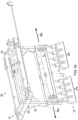
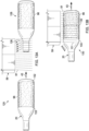
- FIGs. 1 and 2 show perspective views of the decorating machine 10 showing the primary external components of the system.
- Machine 10 includes a material handling or "feed” system portion 11 and a printer system portion 12 mated to one another in a "T" configuration.
- An operator is positioned adjacent to the feed system 11 at a convenient location 14 from which they may load undecorated media 20 onto a loading shuttle 19 positioned in a loading area 13 and adjust the operation of the system 10 through a human machine interface (HMI) via a display terminal (not shown) held by support 24.
- the shuttle 19 is supported by a pair of rails 22 and includes media support brackets 21 that are sized to support a variety of sizes of media 20 in a horizontal orientation.
- the targeted type of undecorated media is a transparent (i.e. visually clear) or semi-transparent (e.g. translucent, frosted or colored glass containers) 3D object.
- Each portion (11,12) of the machine 10 includes suitable support frames 17, external panels 16, and support rollers 18 through which each subsystem is supported.
- shuttle 19 may be moved by the operator from the loading area 13 to a pickup area 25 along rails 22.
- Pickup area 25 is positioned such that a pneumatic robot 26 may grip and raise each undecorated media piece above the shuttle 19 and deliver it onto a printing carriage 28 for conveyance into printing portion 12, or for removal of decorated media 30 from printing carriage 28 and delivery into product removal area 35.
- the removal area may include tilted supports 34 as shown to facilitate removal of decorated product from the machine 10 by an operator.
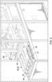
- Fig. 3 shows a closer view of the media handling portion of the system 10 with the printer portion 12 removed.
- pneumatic robot 26 can move either left or right to deposit media from the loading pickup area 25 to the printer carriage 28 or from the printer carriage 28 to the product removal area 35.
- Printer carriage 28 is supported by a portion of printer 12 that is positioned or mated with portion 11 within a vacant section 40 of material handler 11.
- pneumatic robot 26 includes a gantry subassembly 31 having a lower gripper assembly 32 depending downward via vertical supports as shown.
- Gripper assembly 32 includes at least two sets of gripping or grasping mandibles 27(a,b) that are sized to open and close around 3D objects, such as a container like a wine bottle and the like, which are generally referred to herein as "media.”
- a pair of rails 33 are held by gantry 31 to allow for the slidable movement of gripper assembly 32 to slide along a media loading path 29a or along a media unloading path 29b.
- the arrangement allows for the rapid simultaneous movement of two sets of media to and from loading and unloading areas 13 and 35.
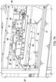
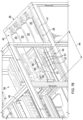
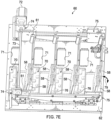
- printer carriage 28 is supported by a pair of rails 41 on a lower enclosure 38 that is sized to fit into space 40 of material handler 11.
- the rails 41 permit printer carriage 28 to traverse from within the handler 11 and into a series of parallel printing tunnels 44 along path 43 and formed within printer section 12. Printing occurs on each piece of undecorated media 20 within these tunnels 44.
- the disclosed embodiment shows 4 tunnels, but the inventors foresee that the number of tunnels may be enlarged to increase material printing throughput to the extent that the material handling section is designed to move material across an increased number of tunnels using an enlarged gripping set.
- Printer 12 includes a lower front enclosure section 38 that is connected to a taller section 39 that holds various printer support subsystems.
- Lower enclosure section 38 houses a standard personal computer or PC 50 that is connected through cables with display terminal (not shown) held by a display terminal support 24 for control of the system 10 via an HMI by an operator.
- a suitable PC for system 10 is a 2.9 GHz Intel Core i7, with 16 GB RAM and an Intel UHD graphics processor 630, and running Windows 10 (HP part No. 2X3K4UT#ABA).
- Section 39 includes an ink delivery subsystem 45 connected and controlled by the personal computer 50 for delivering ink to a series of inkjet printer heads within printer image deposition and curing area 55.
- a suitable print engine and ink recirculation system for system 10 is the available from INX International Ink Co. under part Nos. 99-14080 (Head Drive Mother Board) and 99-14081 (Gen 4 Printhead Control Board) as part of their JetINX TM printhead drive electronics component and ink delivery system offerings.
- tunnels 44 are sized to allow the passage of media 20 underneath section 55 and include a plurality of inkjet heads and UV lamps that are positioned within close proximity to the surface of each piece of media 20 once positioned within each tunnel 44.
- Suitable printheads for printer portion 12 are the Gen 4 Print Heads offered by Ricoh Company, Ltd. under part No. N220792N.
- Suitable UV lamps for both final curing and ink pinning are available from Phoseon Technology under its FireEdge FE400 LED curing line of products (Part No. FE400 80X10 8W).
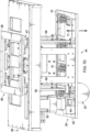
- Fig. 6 shows the tunnel area 44 above which a printhead and cure lamp support assembly 60, including a support gantry 56, are positioned to allow for adjustment of the relative positions of the printheads and cure lamps so that various sizes of media may be accommodated by the printer 12.
- Figs. 7A-7E it may be seen the tiltable arrangement of the pinning UV lamps 58 in relation to the printheads 57 and final cure UV lamps 59.
- Gantry 56 may be raised and lowed in response to operator inputs that set heights in relation to each media size, thereby raising and lowering the printheads 57 and final cure lamps 59 which are affixed and supported by support assembly 60.
- Pinning lamps 58 are also supported by support assembly 60, but are able to be tilted via connected motorized racks 61 as well as move laterally relative to the center of each media piece.
- HMI human machine interface
- a PC actuates movement of the gantry 56 and motorized racks 61 to accommodate the media size.
- a suitable PC/HMI system for the herein described operator control may be found in U.S. Pat. No. US10710378B , at Col. 11, line 19 through Col. 13, line 15, and Figs. 12-13 (commonly owned by the Applicant).
- Actual movement distances are self-generated via PC 50 and communicated electrically to a control board that issues movement commands to motors controlling the racks 61 and gantry height 77.
- a suitable motion control board system for the above may be found in U.S. Pat. No. US 10710378B , at Col. 13, line 16 through Col. 14, line 47, and Fig. 13 (commonly owned by the Applicant).
- Printer support assembly 60 moves vertically (up and down) along path 77, and UV pinning lamps 58 move laterally along path 78 and along angular path 79.
- Motor 63 drives a primary lifting shaft 65 via gearing assembly 64 that in turn drives three passive vertical lifting drive shafts 68.
- a quadrilateral gearing assembly 66 having a fixed support frame 69 fixed to gantry 56 and four corner gearing assemblies 67 connects and supports each drive shaft 68 so that when actuated rotational motor movement is converted into a coordinated level lifting motion of printing support frame 62.
- Frame 62 includes a plurality of slots 70 to fixedly hold printheads above each tunnel 44 and a fixed rearward placed slot 71 for a UV curing lamp.
- each pinning lamp 58 Movement of each pinning lamp 58 is achieved via a coordinated assembly of extendable plates and pivotal support bars and brackets 75.
- Pinning UV lamps 58 are supported by a parallel series of transverse support bars 52 that adjustably hold lamps in pre-formed slots and held in place with retaining screws.
- Each support bar 52 is supported at its ends by brackets 53 and 54 which in turn are supported by connecting plates 61 so that pinning lamps 58 are slidably suspended above each piece of media across and above each tunnel 44.
- End plates 61 are slidable held in slots formed in frame 62 so that as left most plates 61 are moved by gear 47 through gearing assembly 74, the pair of brackets 53 and 54 are moved right or left, depending upon the rotational direction of drive shaft 73 driven by servo motor 72.
- Brackets 53 and 54 are connected to support bars 52 via rotatable studs or fasteners 46 so that as the lateral position of brackets 53 and 54 are changed, bars 52 are correspondingly moved laterally.
- servo motor 72 When actuated, servo motor 72 thereby precisely controls the lateral position of the UV lamps 58 relative to an underlying piece of media 20 positioned within tunnels 44.
- the lateral position of brackets 53 and 54 are also adjustable relative to one another so that as bracket 53 is advanced to the right or left relative to lower bracket 54, bars 52 are tilted about a rotational axis corresponding with the center of the lower positioned rotatable studs 46a.
- brackets 53 and 54 alters the angle 79 of each UV emitter 58 identically with every other UV emitter 58.
- a spring-loaded set pin 49 locks the relative lateral position of each bracket 53 and 54 relative to one another, and upon pulling pin 49 out slightly the two brackets may be altered relative to one another to change angle 79 as desired.
- a series of pin indentations or holes within right most plate 61 allow for the selection and locking of one or more pre-set angles for emitters 58 by grasping and manipulating pin 49 and rotating the UV emitters to a desired angle.
- the lateral position is attained by actuating motor 72 by an operator and, in the present embodiment, the angle of the UV lamps 58 is adjusted by manipulating pin 49 to allow movement and locking of emitters 58 into a desired angle relative to the adjacent printheads 57 and underlying media 20.
- UV lamps 58 in relation to the position of the media 20 and printheads 57 minimizes the potential for UV exposure to each printhead, either directly or via transparent media reflections, as will be further discussed.
- the final cure UV lamp 59 is positioned well behind each bank of inkjet printing heads 57, but the UV pinning lamps 58 are positioned adj acent to each bank of printheads 57 and pointed downward and away from the bottom ink expression area (i.e. the printhead nozzle) of each printhead.
- printing carriage 28 is moved along path 43 and into tunnels 44.
- the media is rotated, and the surface of the media is moved axially under each printhead 57 in a coordinated fashion.
- the lateral position and rotation speed of the media is precisely controlled via spindles 42 and a drive motor causing movement of printing carriage 28 via a screw shaft 48 (not shown).
- spindles 42 are self-stripping and are locked against each piece of media via air cylinders at one end, but having a spring-loaded configuration thereby clamping each piece of media within the print carriage 28 at the center of each individual media spindle.
- the disclosed embodiment shows a material handling system 11 mated to printer 12 so that the disclosed configuration allows for the automation of material handling.
- printer portion 12 may be utilized separately without the automation system 11 in which case an operator would simply load each piece of media 20 directly onto printer carriage 28 by manually manipulating the spindle ends to insert a piece of media 20 for decorating within each spindle and removing a decorated piece of media 30 when complete.
- a suitable ink delivery and print engine subsystem 45 may be found in U.S. Pat. No. US10710378B , at Col. 6, lines 12-47; Col. 7, lines 6-12; Col. 12, line 33 through Col. 13, line 26; and Fig. 4 (commonly owned by the Applicant).
- Fig. 8 along with Table 1 below, a power scale factor formula is presented that allows for the calculation of the minimum amount of power such that a final acceptable UV cure dosage amount may be applied to the partially cured ink present on the surface of the (now) decorated media 30.
- the Power Scale Factor or "PSF" in Table 1 is a dimensionless value and often is simply a scaling factor or a percentage of the maximum power density. Given the amount of energy required to cure the deposited ink and given the known amount of UV energy emitted by lamp 59, a power scale factor or PSF may be calculated using empirical UV dosage results so that the PSF may be utilized for future print jobs. This allows for the variation of various factors during printing to obtain optimal image quality on the exterior of the object 20. For example, if 20% of total dosage during pinning of an image 96 is applied, the lateral speed along path 43 and rotational speed 97 may be varied to accommodate a particular beam strength emitted from lamp 59 to achieve the remaining optimal dosage of 80%. Lamp width 88 is typically small (e.g. 20mm) relative to the circumference of an object 20 such that redundant image exposure may be ignored. Further, each lamp 59 may include a collimator to reduce the fanning or scattering of illumination zone 91 prior to impinging upon the surface of object 20.
- Table 1A Power Scale Factor UV Dosage Applied to Expressed Image During Partial Curing Time of Exposure ⁇ Power Density of the UV Lamp
- the Time of Exposure may be found by dividing the distance of travel of the media under a lamp with the linear velocity of the flat media.
- the time of exposure is the fraction of the time that the UV illumination zone 91 is incident with the expressed image applied to the surface of the media along the perimeter or circumference of the media.
- Fig. 9 shows an altered final cure step 101 to reduce the amount of UV radiation utilized in a final cure step.
- the trailing edge of image 102 i.e. the last part of an image that must be cured as the object moves from left to right and under the cure lamp within tunnel 44
- the trailing edge of image 102 moves under lamp 59 and at some distance 103 becomes fully cured.
- the remaining distance under lamp 59 thereby becomes superfluous for the purpose of curing. Therefore, lamp intensity may be increased during a last portion of lateral travel 103 to finish full curing of the image 96 and then lateral movement stopped rather than moving the object the full length of the image underneath lamp 59. This procedure thereby reduces the time of printing while also reducing the amount of duration of any potentially scattered light within tunnel 44.
- Lamp 59 includes left and right lighting segments 111,112.
- left segment 111 is deactivated and only right segment 112 utilized for curing of ink on image 96, thereby removing the UV illumination field portion between location 114 and 113.
- This re-positions the UV source of light in tunnel 44 to the right and moving a potential source of scattered stray UV light away from ink heads 57.
- This option is selected through an operator inputted action via the HMI prior to the start of any print job.
- Figs 11A-11B , and 12 it may be seen the positioning of pinning lamps relative to the printheads 57 within each tunnel 44.
- the adjustment of the pinning lamp position 78 is accomplished as discussed above with respect to Figs. 7A-7F and may be controlled through an HMI presented to an operator through a display held by display mounting 24.
- the HMI displays the settings required for any selected piece of media and the operator makes whatever adjustments to the printer 12 that are required, including for example the lateral position of the pinning lamps, the tilt or angle of the pinning lamps in relation to the adjacent print heads, and the height of the frame member 62 over the media responsive to the diameter of the media.
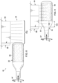
- UV light emitted from lamp 58 is angled such that the right most edge 124 of illumination zone 91 preferably coincides with the tangential edge 123 of object 20 as it rotates 97 in a counterclockwise direction.
- the alignment of the right most zone edge 124 with the object edge 123 allows for the maximum emitted amount of UV light to be received on the rotating surface of the media 20 within the illumination zone 91.
- zone 91 is optionally refined to align the emitted UV light rays with a collimator placed on lamp 58 to further reduce scattering.
- wet ink 119 is jetted or expressed by printhead bank 57 onto the surface of object 20 as the object rotates counter-clockwise.
- the wet ink 119 is then exposed to UV light when it reaches illumination zone 91 and partially hardens into a gel 121 so that the applied ink does not shift on the surface of the media 20 during further printing.
- This arrangement allows for the wet ink to fully spread or "wet" the surface of object 20 prior to exposure to UV radiation in zone 91.
- the slight rotational delay prior to exposure in zone 91 is important because it allows for a better artistic expression of the applied image. For example, the rotational delay allows for a more glossy, desirable image 96 to be applied to the object 20 when fully cured. Referring to Fig.
- clear media will expose ink to UV radiation below the potential tangency point 123 when the UV radiation passes through the clear media material, but given the rotational delay until exposure the point of UV impingement is sufficiently delayed to allow for full wetting of ink on the surface of a clear media object 20 to occur. Further, the downward UV light ray angle minimizes or even eliminates reflections on clear media so that printhead impingement does not occur.
- ink is exposed at the point of tangency 123 on the media with light scattering away from the ink heads 57 to avoid impingement.
- angle 120 of lamp 58 and the lateral position 116 along path 122 of lamp 58 may be adjusted in response to a geometry file associated with the dimensions of object 20 in order to optimize the positioning of lamp 58 so that the right most edge 124 of illumination zone 91 coincides with the tangency point 123. This maximizes the amount of pinning UV radiation applied to the widest possible portion of media 20 without exposing ink heads 57 to UV light, even when clear media are being printed upon with the associated potential reflections of UV light.
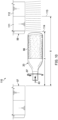
- FIG. 12B it may be seen various positional embodiments 200 of UV lamp 58 and the effect of such positional changes on the UV illumination of rotating media 20.
- Inkjet print heads 57 express ink onto the surface of media 20 in a wet condition 119 as media 20 rotates counterclockwise 97. During rotation, the surface of media 20 rotates into various angular zones demarked by angles of 0 degrees 205, 90 degrees 209, 180 degrees 207, and 270 degrees 208, thereby creating four angular quadrants of 90 degrees each.
- a preferred illumination area 214 may also be seen consisting of plus or minus 45 degrees (212, 213) from angular point 270 degrees 208.
- UV pinning lamp 58 may be moved into various lateral and angular positions 215 thereby altering the position of illumination field 91 issuing from lamp 58.
- inkjet heads 57 and UV lamps 58 are supported by frame member 62 but also extend just below the lower surface 201 of frame member 62 so as to interact with each piece of media 62 when inside tunnels 44 during a printing operation.
- Lamp 58 may be adjusted to move laterally away from printheads 57 along line 203 to various a user selected distances 204(a-c) as measured from the edge of printheads 57 to a center pivot point 202 for lamp 58.
- Pivot point 202 corresponds with retaining grommet 46a (see Fig.
- Each field has a right most illumination edge 124(a-c) that varies with angle and lateral position such that intersection with ink layer 119 on the surface of media 20 creates a tangency point 211(a-c) at the intersection location.
- Each tangency point varies in relation to the lamp position, but is preferably located within preferred angular zone 214 that maximizes the amount of power impinging upon the ink 119 during rotation while minimizing any potential for reflectivity of UV light to intersect the nozzles on printheads 57.
- a preferred position of lateral distance 204b is combined with an angular position of 206b to produce an illumination field of 91b.
- UV light will therefore partially harden ink 119 as is passes through field 91b, including tangency point 211b and keeping wet ink 119 within zones 212 and 213 until gelled.
- lamp 58 By adjusting the lateral and angular position of lamp 58, a large range of media sizes and various types of inks may be accommodated within printer 12 without fouling the ink nozzles of the printheads 57 during printing.
- Figs. 13A-13B show the application of exposure control so as to minimize reflections of UV light during final cure by modulating different banks of emitters in lamp 59 or by modulating the power level of all emitters in lamp 59 ( Fig. 13B).
- Fig. 13A shows the traditional method in which the entire 3D object is moved under a curing lamp for the entire length of the object resulting in the gross scattering of UV radiation 126, likely in a direction toward a printhead 57.
- the same traditional approach shown in Fig. 13A applies with a UV curing lamp emitter positioned underneath the object, which is the most common industry position standard for final curing of ink on 3D objects.
- Fig. 13B shows the improved, modulated approach. Two levels of intensity are used for lamp 59.
- intensity of lamp 59 is set at a value less than full value, for example 50% of full illumination strength, but modulated to an intensity value responsive to a final UV exposure value calculated in accordance with the PSF value to achieve complete curing.
- Object 20 continues to move forward into the illumination zone 91 along path 43.
- the intensity of lamp 59 is increased to full power, or other second higher power depending about size and length of the image and lamp intensity, and again in accordance with the PSF value.
- Fig. 14 shows a process 140 for using the PSF formula shown in Table 1 to control values in the printing process for the system 10.
- the process starts 141 by calculating a PSF by using empirical observations 142.
- an optimal pinning lamp dosage value is determined 143 for the transparent media 20 upon which an image is to be applied.
- the value calculated in step 143 is then subtracted from the total optimal UV dosage amount required to fully cure the image onto the surface of the media 144.
- the PSF is further used to determine the final cure step parameters 146 which are then used to implement a final cure in the print job for a piece of media 147, which ends the printing of a piece of media 148.
- Fig. 15 shows the process steps for adjusting the machine 10 for use on a particular 3D media shape in order to realize the reduced printhead fouling characteristics of the herein described system in a print job.
- Process 150 starts 151 by obtaining the 3D object geometries 152 by either taking manual measurements of the object and inputting those values into the system HMI or by reading into the system a geometry file that specifies the geometry values representing the object from a recipe file provided for the object and its assigned image to be applied. Responsive to the geometries for the object, the height of the printheads 57 held in slots 70 is adjusted 153 up or down along path 77 via commands issued to motor 63 to raise of lower printer support assembly 60.
- the distance is adjusted 153 so that the printheads are optimally spaced 117 from the surface of the media to obtain the best image quality on the surface of the 3D object.
- the lateral position 78 and angle 79 of the UV pinning lamp 58 is adjusted 154 relative to the central rotational axis of the media 20 in order to position the pinning lamp illumination zone edge to be coincident with the tangency 123 of the rotating 3D object surface (see Fig. 12 ).
- the required duration and illumination power for the pinning lamps 58 is calculated and set 155 to control the rotation rate of the media, the lateral advancement 43 and travel speed of printing carriage 28 in system 10.
- the ink representing an image 96 is applied and rotates into the illumination zone 91 to become gelled or "pinned” onto the surface of the object 156. This process of repeatedly applying and pinning an image onto an object surface is repeated until the print job is complete 157 and stopped 158.
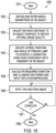
- Fig. 16 shows process steps for adjusting the functionality of a final cure lamp to reduce the potential for printhead fouling 170.
- Some cure lamps 59 utilize one or more parallel segments of LED (light emitting diodes) on their illumination surface of the lamp.
- the printing process of system 10 starts 171 by checking to see if the final cure lamp incorporates selectable LED segments 172. If it does, segments closest to the ink printhead are deactivated 174 in each lamp 59. If the lamp does not include selectable segments, step 174 is skipped. Then, the distance for the trailing edge of the pinned image 96 to travel under the final cure lamp when the lamp is set at full power to fully and optimally cure is determined 176.
- the number of whole rotations of the 3D media to meet the minimum cure distance from step 176 is calculated 177 using the formula shown in Table 2.
- the values calculated in steps 176 and 177 are then used to implement the final cure set in the system 179.
Landscapes
- Engineering & Computer Science (AREA)
- Mechanical Engineering (AREA)
- General Health & Medical Sciences (AREA)
- Toxicology (AREA)
- General Engineering & Computer Science (AREA)
- Health & Medical Sciences (AREA)
- Materials Engineering (AREA)
- Chemical & Material Sciences (AREA)
- Manufacturing & Machinery (AREA)
- Life Sciences & Earth Sciences (AREA)
- Microbiology (AREA)
- Physics & Mathematics (AREA)
- Optics & Photonics (AREA)
- Ink Jet (AREA)
Claims (15)
- Verfahren zur Steuerung der Bewegung eines transparenten Mediums während der Endaushärtung eines Bildes, das auf der Oberfläche dieses transparenten Mediums über einen Tintenstrahldruckkopf dargestellt wird, zur Minimierung der Druckkopfverschlechterung, folgende Schritte umfassend:a. Aufbringen eines Bildes auf die Außenfläche dieses transparenten Mediums, während das genannte Medium gedreht wird;b. Verwenden einer UV-Lampe, um das genannte Bild teilweise in einen gelierten Zustand zu härten, sodass das aufgebrachte Bild auf dieser Außenfläche des genannten Mediums an Ort und Stelle gehalten wird, während Letzteres gedreht wird;c. Bewegen des genannten Mediums seitlich entlang seiner Drehachse in die Nähe einer UV-Aushärtungslampe und UV-Bestrahlung des genannten dargestellten Bilds durch diese Aushärtungslampe, um eine Endaushärtung des genannten Bilds auf dem genannten Medium zu erreichen; und,d. wobei die auf die Außenfläche des genannten Mediums angewendete UV-Strahlung durch diese Endaushärtungslampe während des genannten Schritts der seitlichen Bewegung moduliert wird, sodass sich die Reflexionen des UV-Lichts von dem genannten Medium in Richtung des Tintenstrahldruckkopfes reduzieren, um zu verhindern, dass eine Beeinträchtigung des genannten Tintenstrahldruckkopfs verursacht wird.
- Verfahren nach Anspruch 1, wobei der genannte Schritt der UV-Strahlungsmodulation folgende Schritte umfasst:a. Bestimmen, wann der hinterste Abschnitt des genannten aufgebrachten Bilds in eine UV-Bestrahlungszone eintritt, die durch die genannte Endaushärtungslampe bestimmt wird;b. bei Eintritt des genannten hintersten Abschnitts des genannten aufgebrachten Bilds in die UV-Bestrahlungszone, Erhöhen der UV-Bestrahlungsleistung, die auf das Medium durch die genannte Endaushärtungslampe angewendet wird;c. Bestimmen der seitlichen und Drehbewegung des genannten Mediums, die erforderlich ist, um den genannten hintersten Abschnitt dieses Bilds bei der erhöhten UV-Strahlungsleistung der genannten Endaushärtungslampe vollständig zu härten;d. in Reaktion auf den genannten Schritt zur Bestimmung der seitlichen und Drehbewegung, Bewegen des genannten hintersten Abschnitts des aufgebrachten Bilds weiter in diese UV-Bestrahlungszone, während die genannte UV-Bestrahlungsleistung erhöht wird, bis dieser hinterste Abschnitt optimal gehärtet ist; unde. Beenden der weiteren UV-Bestrahlung des genannten Mediums durch die genannte Endaushärtungslampe, sobald der hinterste Abschnitt des genannten Bilds einen vollständig gehärteten Zustand erreicht, um die Menge der Reflexionen zu reduzieren, die den genannten Tintenstrahldruckkopf potenziell beeinträchtigen,f. optional, wobei der genannte Schritt des Bewegens des hintersten Abschnitts des genannten aufgebrachten Bilds weiter in die genannte UV-Bestrahlungszone den Schritt umfasst, das Medium eine volle Anzahl von Umdrehungen innerhalb der Bestrahlungszone zu drehen, um ein vollständiges Härten zu erreichen, und dann eine weitere Bewegung des Mediums zu stoppen, wobei die genannte volle Anzahl von Umdrehungen gemäß folgender Formel bestimmt wird:
 wobei die Drehgeschwindigkeit des Mediums die Drehgeschwindigkeit des genannten Mediums in Umdrehungen pro Sekunde während des genannten Endaushärtungsschritt repräsentiert;wobei der Umriss des Mediums den Umfang des genannten Mediums an der Stelle des auf der Oberfläche des genannten Mediums dargestellten Bilds in mm repräsentiert;wobei die Dosisdichte die bestimmte optimale Dosierdichte des Pulvers in M Joules pro cm2 für das dargestellte Bild repräsentiert;wobei die Leistungsdichte der UV-Lampe die Gesamtleistungsabgabe in der Endaushärtungslampe in mW per cm2 repräsentiert, undwobei die Lampenbreite die Breite der Aushärtungslampe in mm repräsentiert.
 - Verfahren nach Anspruch 2, wobei der genannte Schritt der UV-Strahlungsmodulation folgende Schritte umfasst:a. Bestimmen, ob die genannte Endaushärtungslampe auswählbare Beleuchtungssegmente aufweist; und,b. in Reaktion auf den genannten Segmentbestimmungsschritt, Deaktivieren auswählbarer Lichtsegmente, die dem genannten Tintenstrahldruckkopf im Endaushärtungsschritt am nächsten sind;c. optional, wobei der genannte Modulationsschritt den Schritt umfasst, die Drehgeschwindigkeit des genannten Mediums, wenn es der UV-Energie ausgesetzt wird, die von einer Endaushärtungslampe emittiert wird, anzupassen.
- Verfahren nach Anspruch 1, wobei der genannte Endaushärtungsschritt folgende Schritte umfasst:a. Berechnen der Menge an UV-Energie, die auf das genannte dargestellte Bild im genannten Teilaushärtungsschritt anzuwenden ist;b. Abziehen des genannten berechneten Werts der UV-Energie zur Teilaushärtung von der genannten festgestellten Menge an UV-Dosierenergie, die notwendig ist, um das genannte dargestellte Bild, das auf das genannte Medium aufgebracht ist, optimal zu härten;c. Anpassen der Menge an UV-Energie, die auf das genannte gelierte Bild im genannten Endaushärtungsschritt angewendet wird, damit sie dem Wert entspricht, der in dem genannten Schritt der Subtraktion von UV-Energie erhalten wird.
- Verfahren nach Anspruch 1, wobei der genannte Schritt der UV-Strahlungsmodulation folgende Schritte umfasst:a. Bestimmen, ob die genannte Endaushärtungslampe auswählbare Beleuchtungssegmente aufweist; und,b. in Reaktion auf den genannten Segmentbestimmungsschritt, Deaktivieren auswählbarer Lichtsegmente, die dem genannten Tintenstrahldruckkopf im Endaushärtungsschritt am nächsten sind;c. optional, wobei der genannte Modulationsschritt ferner den Schritt umfasst, eine Anzahl von Drehungen zu berechnen, die das genannte Medium der UV-Energie ausgesetzt ist, die die Endaushärtungslampe emittiert, und Anpassen der Anzahl von Gesamtdrehungen des genannten Mediums in dem genannten Endaushärtungsschritt, um einer vorab berechneten Anzahl von Drehungen zu entsprechen, die erforderlich ist, um das genannte aufgebrachte Bild optimal zu härten, und Stoppen der weiteren Drehung des genannten Mediums bei Erreichen der genannten vorab berechneten Anzahl von Drehungen.
- Verfahren nach Anspruch 1, wobei der genannte Schritt der UV-Strahlungsmodulation folgende Schritte umfasst:a. Bestimmen der relativen Stelle entlang der Drehachse des genannten Mediums eines konvexen oder konkaven Oberflächenbereichs an der Außenfläche des genannten Mediums, der wahrscheinlich zu Reflexionen von UV-Strahlung führt, die den genannten Tintenstrahldruckkopf während des Endaushärtungsschritts beeinträchtigen, und Aufzeichnen der genannten relativen Stelle;b. während des genannten Teilaushärtungsschritts, Reduzieren der UV-Strahlungsabgabe der genannten Endaushärtungslampe in Bezug auf die maximale Nennstrahlungsabgabe auf einen vorab bestimmten reduzierten Abgabewert;c. gleichzeitig mit dem genannten Teilaushärtungsschritt Bewegen des genannten Mediums entlang seiner Drehachse in ein Bestrahlungsfeld der genannten Endaushärtungslampe, wobei die genannten UV-Strahlungsintensität dieser Endaushärtungslampe auf dem genannten vorab bestimmten reduzierten Abgabewert gehalten wird;d. nach Abschluss des genannten Teilaushärtungsschritts auf die Art, dass die Gesamtheit des aufgebrachten Bilds teilweise in einem gelierten Zustand gehärtet ist, Erhöhen der UV-Strahlungsabgabe der genannten Endaushärtungslampe auf einen vorab bestimmten Wert, der höher als der genannte reduzierte Abgabewert ist, um ein optimales Endhärten des genannten aufgebrachten Bilds zu erreichen; und,e. in Reaktion auf den genannten Schritt der Aufzeichnung eines konvexen oder konkaven Oberflächenbereichs, Stoppen der seitlichen Bewegung entlang der genannten Drehachse des genannten Mediums, wenn dieser aufgezeichnete Oberflächenbereich proximal zu dem genannten Bestrahlungsfeld der Endaushärtungslampe bewegt wird;f. optional, wobei der genannte Modulationsschritt ferner den Schritt umfasst, die Drehgeschwindigkeit des genannten Mediums, wenn es der UV-Energie ausgesetzt ist, die von einer Endaushärtungslampe emittiert wird, anzupassen.
- Verfahren nach Anspruch 1, wobei der genannte Schritt der UV-Strahlungsmodulation folgende Schritte umfasst:a. während des genannten Teilaushärtungsschritts, Reduzieren der UV-Strahlungsabgabe der genannten Endaushärtungslampe in Bezug auf die maximale Nennstrahlungsabgabe auf einen vorab bestimmten reduzierten Abgabewert;b. gleichzeitig mit dem genannten Teilaushärtungsschritt Bewegen des genannten Mediums entlang seiner Drehachse in ein Bestrahlungsfeld der genannten Endaushärtungslampe, wobei die genannte UV-Strahlungsintensität dieser Endaushärtungslampe auf dem genannten vorab bestimmten reduzierten Abgabewert gehalten wird; undc. nach Abschluss des genannten Teilaushärtungsschritts auf die Art, dass die Gesamtheit des aufgebrachten Bilds teilweise in einem gelierten Zustand gehärtet ist, Erhöhen der UV-Strahlungsabgabe der genannten Endaushärtungslampe auf einen vorab bestimmten Wert, der höher als der genannte reduzierte Abgabewert ist, um ein optimales Endhärten des genannten aufgebrachten Bilds zu erreichen.
- Verfahren nach Anspruch 1, wobei der genannte Schritt der UV-Strahlungsmodulation den Schritt umfasst, die UV-Leistungsabgabe der genannten UV-Endaushärtungslampe auf einen vorab bestimmten Wert, der unter der vollen Leistungsabgabe der genannten Endaushärtungslampe liegt, zu reduzieren;
optional, wobei der genannte Endaushärtungsschritt den Schritt umfasst, die seitliche Bewegungsgeschwindigkeit des genannten Mediums entlang seiner Drehachse anzupassen, wenn das genannte Medium der UV-Energie ausgesetzt wird, die von der genannten Endaushärtungslampe emittiert wird. - Verfahren nach Anspruch 8, wobei der genannte Modulationsschritt ferner den Schritt umfasst, eine Anzahl von Drehungen zu berechnen, die das genannte Medium der UV-Energie ausgesetzt ist, die die Endaushärtungslampe emittiert, und Anpassen der Anzahl von Gesamtdrehungen des genannten Mediums in dem genannten Endaushärtungsschritt, um einer vorab berechneten Anzahl von Drehungen zu entsprechen, die erforderlich ist, um das genannte aufgebrachte Bild optimal zu härten, und Stoppen der weiteren Drehung des genannten Mediums bei Erreichen der genannten vorab berechneten Anzahl von Drehungen.
- Verfahren nach Anspruch 1, wobei der genannte Schritt der UV-Strahlungsmodulation den Schritt umfasst, die UV-Leistungsabgabe der genannten UV-Endaushärtungslampe auf einen vorab bestimmten Wert, der unter der vollen Leistungsabgabe der genannten Endaushärtungslampe liegt, zu reduzieren, und die Dreh- und seitliche Geschwindigkeit des genannten Mediums, das sich durch ein Bestrahlungsfeld der genannten Endaushärtungslampe bewegt, in Reaktion auf einen vorab bestimmten Leistungsskalierfaktor anzupassen.
- Verfahren nach Anspruch 10, wobei der genannte Leistungsskalierfaktor gemäß folgender Formel berechnet wird:
 wobei die Drehgeschwindigkeit des Mediums die Drehgeschwindigkeit des genannten Mediums in Umdrehungen pro Sekunde während des genannten Teilaushärtungsschritts repräsentiert;wobei der Schrittabstand pro Medium-Umdrehung den Abstand repräsentiert, den das Medium entlang seiner Drehachse während des genannten Teilaushärtungsschritts während jeder Umdrehung des genannten Mediums zurücklegt, in mm pro Umdrehung;wobei der Umriss des Mediums den Umfang des genannten Mediums am Ort des auf der Außenfläche des genannten Mediums dargestellten Bilds in mm repräsentiert; wobei die Dosisdichte die bestimmte optimale Dosierdichte des Pulvers in M Joules pro cm2 für das dargestellte Bild repräsentiert;wobei der Abstand der Bestrahlung den niedrigeren Wert von der maximalen Bildhöhe wie entlang der Drehachse des genannten Mediums gemessen und der Aushärtungslampenlänge in mm repräsentiert; wobei die Leistungsdichte der UV-Lampe den Gesamtleistungsabgabe in der Aushärtungslampe in mW pro cm2 repräsentiert; undwobei die Lampenbreite die Breite der Aushärtungslampe in mm repräsentiert.
 - Verfahren nach Anspruch 10, wobei der genannte Leistungsskalierfaktor gemäß folgender Formel berechnet wird:
 wobei die angewendete UV-Dosierung die Gesamtmenge der über das dargestellte Bild während des genannten Teilaushärtungsschritts angewendeten UV-Energie in M Joules repräsentiert;wobei die Bestrahlungszeit die Gesamtmenge an Zeit in Sekunden repräsentiert, die das dargestellte Bild innerhalb einer UV-Bestrahlungszone während des genannten Teilaushärtungsschritts der Bestrahlung ausgesetzt ist; undwobei die Leistungsdichte der UV-Lampe die Gesamtleistungsabgabe einer Aushärtungslampe, die im genannten Teilaushärtungsschritt verwendet wird, in mW per cm2 repräsentiert.
 - Verfahren zum Aushärten eines Bilds, das auf die Außenfläche des transparenten Mediums aufgebracht ist, folgende Schritte umfassend:a. Aufbringen eines Bilds auf der Außenfläche dieses transparenten Mediums, während das genannte Medium gedreht wird;b. Verwenden einer UV-Lampe, um das genannte Bild teilweise in einen gelierten Zustand zu härten, sodass das aufgebrachte Bild auf der Außenfläche des genannten Mediums an Ort und Stelle gehalten wird, während Letzteres gedreht wird;c. Bewegen des genannten Mediums in Richtung einer UV-Aushärtungslampe und UV-Bestrahlung des genannten dargestellten Bilds durch diese Aushärtungslampe, um eine Endaushärtung des genannten Bilds auf dem genannten Medium zu erreichen; und,d. wobei die auf die Außenfläche des genannten Mediums angewendete UV-Strahlung durch diese Endaushärtungslampe angepasst und die Bewegung des Mediums angepasst wird, um die Reflexionen des UV-Lichts von dem genannten Medium in Richtung des Tintenstrahldruckkopfes zu reduzieren, um zu verhindern, dass eine Beeinträchtigung des genannten Tintenstrahldruckkopfs verursacht wird.e. optional, wobei der genannte Schritt der UV-Strahlungsanpassung den Schritt umfasst, die UV-Leistungsabgabe der genannten UV-Endaushärtungslampe auf einen vorab bestimmten Wert, der unter der vollen Leistungsabgabe der genannten Endaushärtungslampe liegt, zu reduzieren, und die Dreh- und seitliche Geschwindigkeit des genannten Mediums, das sich durch ein Bestrahlungsfeld der genannten Endaushärtungslampe bewegt, in Reaktion auf einen vorab bestimmten Leistungsskalierfaktor anzupassen.
- Verfahren nach Anspruch 13, wobei der genannte Schritt der UV-Strahlungsanpassung ferner den Schritt umfasst, eine Anzahl von Drehungen zu berechnen, die das genannte Medium der UV-Energie ausgesetzt ist, die die Endaushärtungslampe emittiert, und Anpassen der Anzahl von Gesamtdrehungen des genannten Mediums in dem genannten Endaushärtungsschritt, um einer vorab berechneten Anzahl von Drehungen zu entsprechen, die erforderlich ist, um das genannte aufgebrachte Bild optimal zu härten, und Stoppen der weiteren Drehung des genannten Mediums bei Erreichen der genannten vorab berechneten Anzahl von Drehungen.
- Verfahren nach Anspruch 13, wobei:a. der genannte Schritt, ein Bild auf die Außenfläche des genannten transparenten Mediums aufzubringen, den Schritt umfasst, gleichzeitig Bilder auf eine Vielzahl von Medien aufzubringen, die parallel zueinander relativ zu ihren Drehachsen positioniert sind;b. der genannte Schritt, das genannte Bild teilweise in einen gelierten Zustand zu härten, den Schritt umfasst, gleichzeitig eine Vielzahl von Medien teilweise zu härten, die parallel zueinander relativ zu ihren Drehachsen positioniert sind;c. der genannte Schritt, das genannte Medium in Richtung einer UV-Aushärtungslampe zu bewegen und das genannte dargestellte Bild UV-Licht von der genannten Aushärtungslampe auszusetzen, den Schritt umfasst, gleichzeitig eine Vielzahl von Medien in Richtung einer Vielzahl von UV-Aushärtungslampen zu bewegen und jedes Medium UV-Licht von einer Aushärtungslampe auszusetzen, während alle Medien parallel zueinander relativ zu ihren Drehachsen positioniert sind; undd. während des genannten Schritts der gleichzeitigen Aushärtung jedes Mediums, Modulieren der Menge an UV-Strahlung, die auf jedes Medium angewendet wird, bei gleichzeitiger Anpassung der seitlichen und Drehbewegung jedes Mediums, um die Reflexionen der UV-Strahlung, die in Richtung angrenzend positionierter Tintenstrahldruckköpfe gerichtet sind, zu reduzieren.
Applications Claiming Priority (4)
| Application Number | Priority Date | Filing Date | Title |
|---|---|---|---|
| US202163181740P | 2021-04-29 | 2021-04-29 | |
| US17/342,268 US11396191B1 (en) | 2021-04-29 | 2021-06-08 | Compact media decorator optimized for transparent and semi-transparent media |
| US17/385,275 US11376866B1 (en) | 2021-04-29 | 2021-07-26 | Process for optimization of cure settings in the printing of images on transparent and semi-transparent media |
| PCT/US2021/045775 WO2022231644A1 (en) | 2021-04-29 | 2021-08-12 | Method for controlling the movement of transparent media during final curing to minimize print head degradation |
Publications (4)
| Publication Number | Publication Date |
|---|---|
| EP4100257A1 EP4100257A1 (de) | 2022-12-14 |
| EP4100257A4 EP4100257A4 (de) | 2024-04-24 |
| EP4100257B1 true EP4100257B1 (de) | 2025-04-09 |
| EP4100257C0 EP4100257C0 (de) | 2025-04-09 |
Family
ID=82261351
Family Applications (1)
| Application Number | Title | Priority Date | Filing Date |
|---|---|---|---|
| EP21928355.3A Active EP4100257B1 (de) | 2021-04-29 | 2021-08-12 | Verfahren zur steuerung der bewegung von transparenten medien während der endaushärtung zur minimierung der druckkopfverschlechterung |
Country Status (3)
| Country | Link |
|---|---|
| US (1) | US11376866B1 (de) |
| EP (1) | EP4100257B1 (de) |
| WO (1) | WO2022231644A1 (de) |
Families Citing this family (3)
| Publication number | Priority date | Publication date | Assignee | Title |
|---|---|---|---|---|
| JP6751595B2 (ja) * | 2016-06-02 | 2020-09-09 | 株式会社ミマキエンジニアリング | 造形装置及び造形方法 |
| JP2023104545A (ja) * | 2022-01-18 | 2023-07-28 | セイコーエプソン株式会社 | 印刷制御装置、印刷制御方法、立体物印刷装置、およびコンピュータープログラム |
| CN118761044B (zh) * | 2024-09-06 | 2025-01-03 | 深圳市嘉力电气技术有限公司 | 一种uv变频电源的输出功率控制方法及系统 |
Family Cites Families (13)
| Publication number | Priority date | Publication date | Assignee | Title |
|---|---|---|---|---|
| US6854841B1 (en) | 1998-04-17 | 2005-02-15 | Elesys, Inc. | Point-of-incidence ink-curing mechanisms for radial printing |
| US5873315A (en) | 1998-05-01 | 1999-02-23 | L&P Property Management Company | Combination printing and quilting method and apparatus |
| JP3864903B2 (ja) * | 2002-12-13 | 2007-01-10 | コニカミノルタホールディングス株式会社 | インクジェットプリンタ |
| JP5139843B2 (ja) * | 2008-02-29 | 2013-02-06 | 株式会社ミマキエンジニアリング | インクジェットプリンタ及び印刷方法 |
| US8152290B2 (en) * | 2008-11-26 | 2012-04-10 | Xerox Corporation | Customization of curable ink prints by molding |
| DE102008063837A1 (de) * | 2008-12-19 | 2010-06-24 | Mankiewicz Gebr. & Co. Gmbh & Co Kg | Beschichtung und deren Herstellung mittels Inkjet-Druckverfahren |
| US8628187B2 (en) * | 2010-09-14 | 2014-01-14 | Xerox Corporation | Methods of forming images on substrates with ink partial-curing and contact leveling and apparatuses useful in forming images on substrates |
| EP2675627B1 (de) | 2011-02-14 | 2015-05-06 | Sericol Limited | Tintenstrahldruckverfahren |
| EP2766190B1 (de) * | 2011-10-11 | 2017-09-06 | Hewlett-Packard Industrial Printing Ltd. | Verfahren und vorrichtung zum härten von tinte |
| US10739705B2 (en) * | 2016-08-10 | 2020-08-11 | Ball Corporation | Method and apparatus of decorating a metallic container by digital printing to a transfer blanket |
| CN109572207B (zh) * | 2018-10-31 | 2020-08-04 | 重庆宏劲印务有限责任公司 | 一种光油喷涂形式在瓶体上打印立体图案的装置和方法 |
| WO2020209887A1 (en) * | 2019-04-08 | 2020-10-15 | LSINC Corporation | Method for ink pressure modulation in a printer for axially symmetric objects |
| US11559983B2 (en) | 2019-04-08 | 2023-01-24 | LSINC Corporation | Method for creating a print control profile for printing on a contoured axially symmetric object |
-
2021
- 2021-07-26 US US17/385,275 patent/US11376866B1/en active Active
- 2021-08-12 WO PCT/US2021/045775 patent/WO2022231644A1/en not_active Ceased
- 2021-08-12 EP EP21928355.3A patent/EP4100257B1/de active Active
Also Published As
| Publication number | Publication date |
|---|---|
| US11376866B1 (en) | 2022-07-05 |
| EP4100257A1 (de) | 2022-12-14 |
| EP4100257A4 (de) | 2024-04-24 |
| EP4100257C0 (de) | 2025-04-09 |
| WO2022231644A1 (en) | 2022-11-03 |
Similar Documents
| Publication | Publication Date | Title |
|---|---|---|
| US11312158B1 (en) | Method for partial curing of printed images on transparent and semi-transparent media | |
| EP4100257B1 (de) | Verfahren zur steuerung der bewegung von transparenten medien während der endaushärtung zur minimierung der druckkopfverschlechterung | |
| US11338593B1 (en) | Method for controlling the movement of transparent media during final curing to minimize print head degradation | |
| US10710378B1 (en) | Printing system for applying images over a contoured axially symmetric object | |
| CA1277176C (en) | Process and apparatus for decorating a container | |
| US11850845B2 (en) | Method for creating a print control profile for printing on a contoured axially symmetric object | |
| US20100039487A1 (en) | Digital Ink Jet Printer and Process | |
| US11396191B1 (en) | Compact media decorator optimized for transparent and semi-transparent media | |
| JP4867754B2 (ja) | 三次元表面の印刷方法 | |
| US20160236483A1 (en) | Cyclically operating printing press | |
| US20230128066A1 (en) | Reconfigurable Single Media Printer Having a Positionable Media Support Carriage | |
| US11813844B2 (en) | Method for reconfiguring a media printer to optimize single media printing | |
| US11787203B2 (en) | System and method for hollow vessel printing | |
| CN121038967A (zh) | 用于在封盖上进行印刷的喷墨数字印刷机 | |
| HK1208011B (en) | Machine for the decoration of tridimensional products | |
| HK1208011A1 (en) | Machine for the decoration of tridimensional products |
Legal Events
| Date | Code | Title | Description |
|---|---|---|---|
| STAA | Information on the status of an ep patent application or granted ep patent |
Free format text: STATUS: UNKNOWN |
|
| STAA | Information on the status of an ep patent application or granted ep patent |
Free format text: STATUS: THE INTERNATIONAL PUBLICATION HAS BEEN MADE |
|
| PUAI | Public reference made under article 153(3) epc to a published international application that has entered the european phase |
Free format text: ORIGINAL CODE: 0009012 |
|
| STAA | Information on the status of an ep patent application or granted ep patent |
Free format text: STATUS: REQUEST FOR EXAMINATION WAS MADE |
|
| 17P | Request for examination filed |
Effective date: 20220907 |
|
| AK | Designated contracting states |
Kind code of ref document: A1 Designated state(s): AL AT BE BG CH CY CZ DE DK EE ES FI FR GB GR HR HU IE IS IT LI LT LU LV MC MK MT NL NO PL PT RO RS SE SI SK SM TR |
|
| REG | Reference to a national code |
Ref country code: DE Ref legal event code: R079 Free format text: PREVIOUS MAIN CLASS: B41J0002447000 Ipc: B41J0003407000 Ref document number: 602021029082 Country of ref document: DE |
|
| A4 | Supplementary search report drawn up and despatched |
Effective date: 20240322 |
|
| RIC1 | Information provided on ipc code assigned before grant |
Ipc: F26B 15/12 20060101ALI20240318BHEP Ipc: F26B 3/28 20060101ALI20240318BHEP Ipc: B41J 11/00 20060101ALI20240318BHEP Ipc: B41J 3/407 20060101AFI20240318BHEP |
|
| DAV | Request for validation of the european patent (deleted) | ||
| DAX | Request for extension of the european patent (deleted) | ||
| GRAP | Despatch of communication of intention to grant a patent |
Free format text: ORIGINAL CODE: EPIDOSNIGR1 |
|
| STAA | Information on the status of an ep patent application or granted ep patent |
Free format text: STATUS: GRANT OF PATENT IS INTENDED |
|
| INTG | Intention to grant announced |
Effective date: 20241119 |
|
| GRAS | Grant fee paid |
Free format text: ORIGINAL CODE: EPIDOSNIGR3 |
|
| GRAA | (expected) grant |
Free format text: ORIGINAL CODE: 0009210 |
|
| STAA | Information on the status of an ep patent application or granted ep patent |
Free format text: STATUS: THE PATENT HAS BEEN GRANTED |
|
| AK | Designated contracting states |
Kind code of ref document: B1 Designated state(s): AL AT BE BG CH CY CZ DE DK EE ES FI FR GB GR HR HU IE IS IT LI LT LU LV MC MK MT NL NO PL PT RO RS SE SI SK SM TR |
|
| REG | Reference to a national code |
Ref country code: GB Ref legal event code: FG4D |
|
| REG | Reference to a national code |
Ref country code: CH Ref legal event code: EP |
|
| REG | Reference to a national code |
Ref country code: DE Ref legal event code: R096 Ref document number: 602021029082 Country of ref document: DE |
|
| REG | Reference to a national code |
Ref country code: IE Ref legal event code: FG4D |
|
| U01 | Request for unitary effect filed |
Effective date: 20250417 |
|
| U07 | Unitary effect registered |
Designated state(s): AT BE BG DE DK EE FI FR IT LT LU LV MT NL PT RO SE SI Effective date: 20250425 |
|
| U20 | Renewal fee for the european patent with unitary effect paid |
Year of fee payment: 5 Effective date: 20250815 |
|
| PG25 | Lapsed in a contracting state [announced via postgrant information from national office to epo] |
Ref country code: ES Free format text: LAPSE BECAUSE OF FAILURE TO SUBMIT A TRANSLATION OF THE DESCRIPTION OR TO PAY THE FEE WITHIN THE PRESCRIBED TIME-LIMIT Effective date: 20250409 |
|
| PG25 | Lapsed in a contracting state [announced via postgrant information from national office to epo] |
Ref country code: NO Free format text: LAPSE BECAUSE OF FAILURE TO SUBMIT A TRANSLATION OF THE DESCRIPTION OR TO PAY THE FEE WITHIN THE PRESCRIBED TIME-LIMIT Effective date: 20250709 Ref country code: GR Free format text: LAPSE BECAUSE OF FAILURE TO SUBMIT A TRANSLATION OF THE DESCRIPTION OR TO PAY THE FEE WITHIN THE PRESCRIBED TIME-LIMIT Effective date: 20250710 |
|
| PG25 | Lapsed in a contracting state [announced via postgrant information from national office to epo] |
Ref country code: PL Free format text: LAPSE BECAUSE OF FAILURE TO SUBMIT A TRANSLATION OF THE DESCRIPTION OR TO PAY THE FEE WITHIN THE PRESCRIBED TIME-LIMIT Effective date: 20250409 |
|
| PGFP | Annual fee paid to national office [announced via postgrant information from national office to epo] |
Ref country code: GB Payment date: 20250815 Year of fee payment: 5 |
|
| PG25 | Lapsed in a contracting state [announced via postgrant information from national office to epo] |
Ref country code: HR Free format text: LAPSE BECAUSE OF FAILURE TO SUBMIT A TRANSLATION OF THE DESCRIPTION OR TO PAY THE FEE WITHIN THE PRESCRIBED TIME-LIMIT Effective date: 20250409 |
|
| PG25 | Lapsed in a contracting state [announced via postgrant information from national office to epo] |
Ref country code: RS Free format text: LAPSE BECAUSE OF FAILURE TO SUBMIT A TRANSLATION OF THE DESCRIPTION OR TO PAY THE FEE WITHIN THE PRESCRIBED TIME-LIMIT Effective date: 20250709 |
|
| PG25 | Lapsed in a contracting state [announced via postgrant information from national office to epo] |
Ref country code: IS Free format text: LAPSE BECAUSE OF FAILURE TO SUBMIT A TRANSLATION OF THE DESCRIPTION OR TO PAY THE FEE WITHIN THE PRESCRIBED TIME-LIMIT Effective date: 20250809 |
|
| U1N | Appointed representative for the unitary patent procedure changed after the registration of the unitary effect |
Representative=s name: WITHERS & ROGERS; GB |