EP4100179B1 - Welding machine - Google Patents
Welding machine Download PDFInfo
- Publication number
- EP4100179B1 EP4100179B1 EP21708070.4A EP21708070A EP4100179B1 EP 4100179 B1 EP4100179 B1 EP 4100179B1 EP 21708070 A EP21708070 A EP 21708070A EP 4100179 B1 EP4100179 B1 EP 4100179B1
- Authority
- EP
- European Patent Office
- Prior art keywords
- carriage
- welding machine
- machine according
- hole
- clamping means
- Prior art date
- Legal status (The legal status is an assumption and is not a legal conclusion. Google has not performed a legal analysis and makes no representation as to the accuracy of the status listed.)
- Active
Links
Images


Classifications
-
- B—PERFORMING OPERATIONS; TRANSPORTING
- B23—MACHINE TOOLS; METAL-WORKING NOT OTHERWISE PROVIDED FOR
- B23K—SOLDERING OR UNSOLDERING; WELDING; CLADDING OR PLATING BY SOLDERING OR WELDING; CUTTING BY APPLYING HEAT LOCALLY, e.g. FLAME CUTTING; WORKING BY LASER BEAM
- B23K11/00—Resistance welding; Severing by resistance heating
- B23K11/04—Flash butt welding
- B23K11/046—Apparatus therefor
-
- B—PERFORMING OPERATIONS; TRANSPORTING
- B21—MECHANICAL METAL-WORKING WITHOUT ESSENTIALLY REMOVING MATERIAL; PUNCHING METAL
- B21B—ROLLING OF METAL
- B21B15/00—Arrangements for performing additional metal-working operations specially combined with or arranged in, or specially adapted for use in connection with, metal-rolling mills
- B21B15/0085—Joining ends of material to continuous strip, bar or sheet
Definitions
- the present invention relates to a welding machine, preferably of the flash welding type, for longitudinal metal products, e.g. billets, bars or blooms, adapted to weld the head and tail of two consecutive longitudinal products to each other along a roller pathway, usually arranged upstream of a rolling mill.
- EP3578276A1 discloses a welding machine according to the preamble of claim 1.
- the metal products from the casting machine or from external warehouses are welded together and then seamlessly rolled.
- the metal products, which are welded, are typically semifinished casting products, e.g. such as, billets, bars or blooms.
- the welding is carried out by joining the tail of one product to the head of the successive product.
- the welding is achieved by means of electric arcs produced by power supplies connected to the products to be welded. This technology is known as flash welding.
- clamping means serve to keep the products in place while welding and that often act also as conductors of the welding electric current.
- Such clamping means typically comprise elements, in particular clamps, which come directly into contact with the products to be welded. Gradually as the welding is carried out, the clamps, which hold the head and tail of the products to be welded, are brought close by means of hydraulic cylinders, named upsetting cylinders. This operation is necessary to join the ends to be welded, to eliminate any inclusions and air bubbles and to compensate for the loss of material, in the form of burrs, determined by the melting, and to allow the effective adhesion between the two components being welded, which form a joint, named weld joint.
- a known type of flash butt welding machine generally comprises two structures, each provided with a pair of clamps, the structures being substantially parallel to each other and inclined at an angle of about 45° relative to the plane defined by the carriage supporting the machine. Said inclination allows a uniform application of the contact force of the clamps with the product on the sides thereof, thus allowing its optimal retention and centering.
- the transformer provided with conductors connected to the two structures to supply electric current to the tail and head of the two products to be welded, is located above the inclined upper surfaces of the two structures, which makes access and, consequently, maintenance of the internal parts of the machine difficult. Even the disassembly and removal of heavy parts from the machine become difficult operations which must be carried out manually by the operators, who must enter inside the machine in difficult conditions.
- the present invention achieves at least one of such objects and other objects which will be apparent in light of the present description, by means of a welding machine, preferably of the flash butt welding type, to weld the tail of a first longitudinal metal product together with the head of a second longitudinal metal product along a feeding direction X of said longitudinal metal products, the machine comprising a carriage adapted to slide along the feeding direction X, said carriage supporting
- the transformer is integrally fixed to the carriage and, not being positioned above the two structures, access from above and, consequently, maintenance of the internal parts of the machine are facilitated. Disassembly and removal of heavy parts and components from the machine also become extremely simple operations, which can be carried out with common aids, such as cranes and overhead cranes.
- the machine components subject to maintenance are accessible and can be lifted from above.
- the conductors which connect the transformer to the first clamping means and the second clamping means, respectively pass underneath the first structure and the second structure, respectively, so that both the space between the first clamping means and the space between the second clamping means are freely accessible from below in the absence of longitudinal metal products to be welded.
- a further advantage is represented by the variant in which the second structure can slide, parallel to the feeding direction and relative to both the first structure and the carriage, on two beams, which are part of the carriage itself and which delimit said first part of the carriage, or can slide on two further beams, distinct from the beams of the carriage, which are part of a lifting system adapted to lift together both the first structure and the second structure with respect to the carriage by means of a rotation of a predetermined angle along a plane which is transverse to said feeding direction.
- the configuration of the welding machine according to the invention allows to make a drainage floor underneath it, which can be at a distance of less than 1.5 meters from the product passline, preferably less than 1 meter. This means lower costs for the realization of the foundations of the production line.
- the welding machine which is suitable for welding the tail of a first longitudinal metal product to the head of a second longitudinal metal product along a feeding direction X of said longitudinal metal products, comprises a carriage 1, adapted to slide on at least two sliding guides 20, 30 along said feeding direction X above a roller path (not shown) on which the longitudinal metal products, such as billets, blooms or bars, advance.
- the carriage 1 supports:
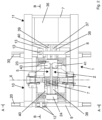
- the first structure 2 defines a longitudinal axis Z ( Figure 1 ), inclined relative to a horizontal plane, by an acute angle, preferably between 30° and 70°, e.g. 45°.
- the second structure 5, defining an own longitudinal axis Z' parallel to the longitudinal axis Z ( Figure 1 ), is arranged substantially parallel to the first structure 2 and spaced from the latter along the feeding direction X of the products to be welded.
- first structure 2 and the second structure 5 substantially parallel to each other, define a respective longitudinal axis arranged substantially horizontally.
- At least one infeed guide and at least one outfeed guide are optionally provided for the infeed and outfeed of metal products from the welding machine, each guide being constrained to a respective structure 2, 5 along the feeding axis X.
- said guides can be part of the carriage 1.
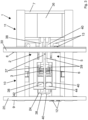
- both the first clamping means 3, 4 and the second clamping means 6, 7 are possibly adjustable in position by means of respective moving systems 41, 42; 43, 44 provided on the first structure 2 and on the second structure 5, respectively ( Figure 2 and 3 ).
- Such moving systems comprise, for example, hydraulic cylinders or jacks, or electric actuators or mechanical moving devices, such as cam or eccentric devices.
- first clamping means 3, 4 of the first structure 2 comprise a respective upper clamp 3 and a respective lower clamp 4.
- Each clamp 3, 4 can be moved along the Z-axis by a respective moving system 41, 42 ( Figures 2 and 3 ).
- the second clamping means 6, 7 of the second structure 5 comprise a respective upper clamp 6 and a respective lower clamp 7.
- each clamp 6, 7 can be possibly moved along the Z'-axis by a respective moving system 43, 44 ( Figures 2 and 3 ).
- the movement, and therefore the adjustability, of all the clamps of the clamping means advantageously eliminates the need to have to incline or rotate slightly the two structures 2, 5 to prevent the metal product, e.g. the billet, from slipping on the lower clamps, which are fixed in the machines of the prior art.
- the first structure 2 and the second structure 5 are supported, and possibly also contained, in a first part 10 of the carriage 1 delimited by a first beam 9 and a second beam 8 of the carriage that are parallel to each other and to the feeding direction X, while the at least one transformer 36 is fixed to the carriage 1 and supported, and possibly also contained, entirely in a second part 11 of the carriage 1, arranged laterally outside the first part 10.
- the transformer 36 can be a single transformer. Alternatively, a group of transformers can be provided which concur to electrically supply the clamps 3, 4, 6, 7 by means of the conductors 37, 38, 39, 40.
- the second part 11 of the carriage 1 can be delimited by said second beam 8 and a third beam 7 of the carriage 1, preferably parallel to the second beam 8.
- the first beam 9 and the third beam 7 are peripheral beams of the carriage 1 while the second beam 8 is an intermediate beam.
- At least two further peripheral beams, which are transverse, preferably perpendicular, to the beams 9, 8, 7 are provided to define the perimeter of the carriage 1 together with the beams 9 and 7.
- the carriage 1 is preferably arranged on two sliding guides 20, 30 fixed, either directly or by means of frames, on a floor below the welding machine, said sliding guides being parallel to each other and to the axis X.
- the first beam 9 and the second beam 8 of the carriage 1 are positioned at a respective sliding guide 20, 30.
- the first part 10 of the carriage 1 is above and at an area delimited by the sliding guides 20, 30.
- the second beam 8 is positioned at the sliding guide 30, while the third beam 7 is positioned at the sliding guide 20.
- the second part 11 of the carriage 1 is above and at the area delimited by the sliding guides 20, 30.
- the beams 9, 8 or the beams 8, 7 could also be offset relative to the sliding guides 20, 30.
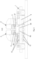
- the conductors 37, 38 and 39, 40 connect the transformer 36 to the first clamping means 3, 4 and to the second clamping means 6, 7, respectively, passing underneath the first structure 2 and the second structure 5, respectively, in order to leave both the space between the first clamping means 3, 4 and the space between the second clamping means 6, 7 freely accessible from below in the absence of longitudinal metal products to be welded.
- the upper conductors 37, 39 exiting the transformer 36 can advance parallel to each other by passing for a small stretch respectively below the first structure 2 and the second structure 5 until arriving in proximity of the respective upper clamps 3 and 6.
- the pattern of the current is such that the circuit closes between the upper clamps 3 and 6 of the two structures.
- the lower conductors 38, 40 exiting from the transformer 36 can advance parallel to each other with a first stretch thereof below the first structure 2 and the second structure 5, respectively.
- the lower conductors 38, 40 can deviate by moving away from each other with a second stretch thereof and then advance parallel to each other again with a third stretch thereof, and approach each other again in proximity of the foot of the first structure 2 and of the second structure 5 with a fourth stretch thereof.
- a fifth and final stretch of the conductors 38, 40 finally arrives in proximity of the respective lower clamps 4 and 7.
- the pattern of the current is such that the circuit closes between the lower clamps 4 and 7 of the two structures.
- the configuration of the stretches of the lower conductors 38, 40 is thus designed to leave completely accessible from below at least the area comprising the clamping means 3, 4 and 6, 7.
- both the space between the first clamping means 3, 4 and the space between the second clamping means 6, 7 are freely accessible both from above and below in the absence of longitudinal metal products to be welded.
- the variant comprising two or more transformers in the second part 11 of the carriage 1, e.g. only two transformers arranged on top of each other, a first upper conductor and a first lower conductor exit the respective transformer and respectively reach the clamps 3, 4 of the first structure 2; while a second upper conductor and a second lower conductor exit the respective transformer and respectively reach the clamps 6, 7 of the second structure 5.
- the pattern of the currents is such that the two circuits close between the upper clamps 3 and 6 and between the lower clamps 4 and 7, respectively.
- the conductors can be arranged in configurations other than those described above, while maintaining free access from below to both the space between the first clamping means 3, 4 and the space between the second clamping means 6, 7, in the absence of the longitudinal metal products to be welded.
- the first structure 2 and the second structure 5, in addition to being arranged substantially parallel to each other, are arranged transversely, preferably orthogonally, to the first beam 9 and the second beam 8.
- the first beam 9 and the second beam 8 have a respective first portion, proximal to the first structure 2 and to which said first structure 2 is integrally fixed, and a respective second portion, distal from the first structure 2 and to which the second structure 5 is slidingly connected.
- the second portion of the first beam 9 is inserted in a first through-hole 21 of the second structure 5 ( Figures 1 and 5 ) internally provided with first rolls or pads 12 for a sliding of the second structure 5 on the first beam 9; and the second portion of the second beam 8 is inserted in a second through-hole 22 of the second structure 5 ( Figure 5 ) provided internally with second rolls or pads 13 for a sliding of the second structure 5 on the second beam 8.
- both the second portion of the first beam 9 and the first through-hole 21 have a quadrangular cross-section, and said first through-hole 21 is provided with first rolls or pads 12 only on two mutually opposite inner sides ( Figure 5 ), preferably above and below the first beam 9.
- a pair of first rolls 12 is provided on each of said two inner sides ( Figure 4 ).
- the second portion of the second beam 8 and the second through-hole 22 can have a quadrangular section, and said second through-hole 22 is provided with at least one second roll or pad 13 on at least three of its inner sides.
- four rolls or pads 13 are provided, one on each of the inner sides of the through-hole 22.
- first rolls 12 are idle, accommodated in respective seats obtained in the second structure 5 and protruding into the first through-hole 21 to come into contact with mutually opposite surfaces of the first beam 9; and also the second rolls 13 are idle, accommodated in respective seats obtained in the second structure 5 and protruding into the second through-hole 22 to come into contact with the respective side surface of the second beam 8.
- both the second portion of the first beam 9 and the first through-hole 21 have a round section, and said first through-hole 21 is provided with first pads 12; and both the second portion of the second beam 8 and the second through-hole 22 have a round section and said second through-hole 22 is provided with second pads 13.
- the sliding of the second structure 5 on the beams 9 and 8 can alternatively be achieved by reversing the configuration of the rolls or pads between the two through-holes 21, 22. Therefore, the first through-hole 21 of the second structure 5 can be internally provided with at least three rolls or pads 13 for a sliding of the second structure 5 on the first beam 9; and the second through-hole 22 of the second structure 5 can be internally provided with second rolls or pads 12, only on two internal sides opposite to each other, for a sliding of the second structure 5 on the second beam 8.
- a second variant shown in Figures 8 and 9 , provides that the first structure 2 and the second structure 5 are supported in the first part 10 of the carriage 1 not by means of the beams 8 and 9 of the carriage itself, but instead by means of a lifting system adapted to lifting said first structure 2 and said second structure 5 together with respect to the carriage 1, by means of a rotation along a plane which is transverse to the feeding direction X.
- a rotation can be in the range of 1° to 25°, e.g. 1° to 15°.
- Said lifting system preferably of the linkage type, comprises:
- the longitudinal axes of the first rotating shaft 19 and the second rotating shaft 18 are parallel and arranged on a first horizontal plane.
- the longitudinal axes of the further first beam 29 and the further second beam 28 are also parallel and arranged on a second horizontal plane, located above the first horizontal plane.
- the relative position between each rotating shaft 18, 19 and the corresponding further beam 28, 29 is such that the levers 45, 46 are always inclined at an acute angle other than zero with respect to the vertical.
- the further first beam 29 and the further second beam 28 support both the first structure 2 and the second structure 5, which are arranged substantially parallel to each other and transversely, preferably orthogonally, to said further first beam 29 and said further second beam 28.
- At least one actuator 47 is provided, adapted to rotate the first rotating shaft 19 and/or the second rotating shaft 18 by a predetermined angle so that the first structure 2 and the second structure 5 can be lifted together with respect to the carriage 1.
- only one actuator 47 is provided, e.g. fixed on the beam 8 of the carriage 1, which acts on a further lever 49 of the second rotating shaft 18.
- a connecting rod or tie rod 48 can synchronize the rotations of the two rotating shafts 18, 19, facilitating the lifting, by rotation, of the further beams 28, 29.
- the further first beam 29 and said further second beam 28 have a respective first portion, which is proximal to the first structure 2 and to which said first structure 2 is integrally fixed, and a respective second portion, which is distal from the first structure 2 and to which the second structure 5 is slidingly connected.
- the second portion of the further first beam 29 is inserted into a first through-hole 21 of the second structure 5, internally provided with first rolls or pads for a sliding of the second structure 5 on said further first beam 29; and the second portion of the further second beam 28 is inserted into a second through-hole 22 of the second structure 5, internally provided with second rolls or pads for a sliding of the second structure 5 on said further second beam 28.
- both the second portion of the further first beam 29 and the first through-hole 21 have a quadrangular cross-section, and said first through-hole 21 is provided with first rolls or pads only on two inner sides opposite to each other (in a manner similar to Figure 5 ), preferably above and below the beam 29.
- a pair of first rolls is provided on each of said two inner sides (in a manner similar to Figure 4 ).
- the second portion of the further second beam 28 and the second through-hole 22 can have a quadrangular section and said second through-hole 22 is provided with at least one second roll or pad on at least three of its inner sides.
- the first rolls are idle, accommodated in respective seats obtained in the second structure 5 and protruding into the first through-hole 21 to come into contact with mutually opposite surfaces of the further first beam 29; and also the second rolls are idle, accommodated in respective seats in the second structure 5 and protruding into the second through-hole 22 to come into contact with the respective side surface of the further second beam 28.
- both the second portion of the further first beam 29 and the first through-hole 21 have a round section, and said first through-hole 21 is provided with first pads; and both the second portion of the further second beam 28 and the second through-hole 22 have a round section and said second through-hole 22 is provided with second pads.
- the sliding of the second structure 5 on the further beams 29 and 28 can alternatively be achieved by reversing the configuration of the rolls or pads between the two through-holes 21, 22. Therefore, the first through-hole 21 of the second structure 5 can be internally provided with at least three second rolls or pads for a sliding of the second structure 5 on the further first beam 9; and the second through-hole 22 of the second structure 5 can be internally provided with first rolls or pads, only on two internal sides opposite to each other, for a sliding of the second structure 5 on the further second beam 28.
- a further advantage of the invention can be that of making the carriage 1 provided with at least one motor 31 connected to a toothed wheel 32 adapted to engage a rack 33 provided on at least one of the sliding guides 20, 30 ( Figure 6 ), preferably on one of the sides of the sliding guide.
- adjustment means 23, 24 can be provided for moving the second structure 5 towards or away from the first structure 2 along said feeding direction X.
- the approaching is made, in particular, when welding two products by flash welding.
- said adjustment means are upsetting cylinders 23, 24, which preferably are two in number.
- the upsetting cylinders 23, 24 are pivoted at a first end thereof to the first structure 2 and at a second end thereof to the second structure 5 by means of respective pins.
- a first upsetting cylinder 23 is arranged inferiorly behind both the first structure 2 and the second structure 5.
- the second upsetting cylinder 24 is arranged substantially at the feet of both the first structure 2 and the second structure 5.
- the two upsetting cylinders 23, 24 are arranged along a same substantially horizontal plane.
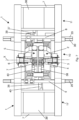
- FIG. 7 A second embodiment of the welding machine of the invention is shown in Figure 7 .
- the description provided above for the first embodiment also applies to this second embodiment.
- the latter differs from the first embodiment in that it provides for:
- the first part 10 of the carriage 1 is delimited by the first beam 9 and by the second beam 8 of the carriage 1, which are parallel to the feeding direction X.
- the second part 11 of the carriage 1 is delimited by said second beam 8 and by a third beam 7 of the carriage 1, preferably parallel to the second beam 8.
- the third part 11' of the carriage 1 is delimited by said first beam 9 and by a fourth beam 7', preferably parallel to the first beam 9.
- the fourth beam 7' and the third beam 7 are peripheral beams of the carriage 1 while the first beam 9 and the second beam 8 are intermediate beams of the carriage.
- At least two further peripheral beams which are transverse, preferably perpendicular, to the beams 7', 9, 8, 7 are provided to define the perimeter of the carriage 1 together with the beams 7' and 7.
- an upper conductor 37 and a lower conductor 39 exit the first transformer 36 and reach the upper clamps 3 and 6 of the structures 2 and 5, respectively; while an upper conductor 40 and a lower conductor 38 exit the second transformer 36' and reach the lower clamps 4 and 7 of the structures 2 and 5, respectively.
- the pattern of the currents is such that the two circuits close between the upper clamps 3 and 6 and between the lower clamps 4 and 7, respectively.
- a third embodiment of the welding machine of the invention differs from the aforementioned second embodiment in that it provides:
- the second structure 5 is arranged substantially parallel to the first structure 2 and spaced therefrom along the feeding direction X of the products to be welded.
Landscapes
- Engineering & Computer Science (AREA)
- Mechanical Engineering (AREA)
- Butt Welding And Welding Of Specific Article (AREA)
- Laser Beam Processing (AREA)
- Arc Welding In General (AREA)
- Resistance Welding (AREA)
- Automatic Assembly (AREA)
Description
- The present invention relates to a welding machine, preferably of the flash welding type, for longitudinal metal products, e.g. billets, bars or blooms, adapted to weld the head and tail of two consecutive longitudinal products to each other along a roller pathway, usually arranged upstream of a rolling mill.
EP3578276A1 discloses a welding machine according to the preamble ofclaim 1. - In rolling mills, in particular of the endless type, the metal products from the casting machine or from external warehouses are welded together and then seamlessly rolled. The metal products, which are welded, are typically semifinished casting products, e.g. such as, billets, bars or blooms.
- The welding is carried out by joining the tail of one product to the head of the successive product.
- The welding is achieved by means of electric arcs produced by power supplies connected to the products to be welded. This technology is known as flash welding.
- During welding, the products must be effectively blocked. To this end, clamping means are provided, which serve to keep the products in place while welding and that often act also as conductors of the welding electric current.
- Such clamping means typically comprise elements, in particular clamps, which come directly into contact with the products to be welded. Gradually as the welding is carried out, the clamps, which hold the head and tail of the products to be welded, are brought close by means of hydraulic cylinders, named upsetting cylinders. This operation is necessary to join the ends to be welded, to eliminate any inclusions and air bubbles and to compensate for the loss of material, in the form of burrs, determined by the melting, and to allow the effective adhesion between the two components being welded, which form a joint, named weld joint. A known type of flash butt welding machine generally comprises two structures, each provided with a pair of clamps, the structures being substantially parallel to each other and inclined at an angle of about 45° relative to the plane defined by the carriage supporting the machine. Said inclination allows a uniform application of the contact force of the clamps with the product on the sides thereof, thus allowing its optimal retention and centering.
- Disadvantageously, the transformer, provided with conductors connected to the two structures to supply electric current to the tail and head of the two products to be welded, is located above the inclined upper surfaces of the two structures, which makes access and, consequently, maintenance of the internal parts of the machine difficult. Even the disassembly and removal of heavy parts from the machine become difficult operations which must be carried out manually by the operators, who must enter inside the machine in difficult conditions.
- Therefore, there is a need to solve at least the aforesaid drawback by making a welding machine, which can offer easy maintenance and the possibility to operate with aids, such as cranes and bridge cranes, for the clearing heavy bodies.
- It is an object of the present invention to produce a welding machine, preferably of the flash butt welding type, which allows easy access to the internal parts of the clamp-holding structures, allowing rapid maintenance and cleaning, and allowing the possibility to operate with common aids, such as cranes and overhead cranes, for clearing heavy components.
- It is another object of the present invention to produce a welding machine, which is simple from a structural point of view, and which nonetheless allows the movements required by the known welding machines to be carried out.
- It is a further object of the present invention to produce a welding machine which makes it possible to increase safety for operators.
- The present invention achieves at least one of such objects and other objects which will be apparent in light of the present description, by means of a welding machine, preferably of the flash butt welding type, to weld the tail of a first longitudinal metal product together with the head of a second longitudinal metal product along a feeding direction X of said longitudinal metal products, the machine comprising a carriage adapted to slide along the feeding direction X, said carriage supporting
- a first structure connected to said carriage;
- first clamping means, provided on said first structure, to clamp either the tail of the first metal product or the head of the second metal product;
- a second structure sliding parallel to the feeding direction, with respect to both the first structure and the carriage;
- second clamping means, provided on said second structure, to clamp either the head of the second metal product or the tail of the first metal product;
- at least one transformer provided with conductors connected to the first clamping means and to the second clamping means, respectively, to supply electric current to said tail and said head;
- Advantageously, the transformer is integrally fixed to the carriage and, not being positioned above the two structures, access from above and, consequently, maintenance of the internal parts of the machine are facilitated. Disassembly and removal of heavy parts and components from the machine also become extremely simple operations, which can be carried out with common aids, such as cranes and overhead cranes. Advantageously, the machine components subject to maintenance are accessible and can be lifted from above.
- Preferably, the conductors which connect the transformer to the first clamping means and the second clamping means, respectively, pass underneath the first structure and the second structure, respectively, so that both the space between the first clamping means and the space between the second clamping means are freely accessible from below in the absence of longitudinal metal products to be welded.
- A further advantage is represented by the variant in which the second structure can slide, parallel to the feeding direction and relative to both the first structure and the carriage, on two beams, which are part of the carriage itself and which delimit said first part of the carriage, or can slide on two further beams, distinct from the beams of the carriage, which are part of a lifting system adapted to lift together both the first structure and the second structure with respect to the carriage by means of a rotation of a predetermined angle along a plane which is transverse to said feeding direction.
- Furthermore, the configuration of the welding machine according to the invention allows to make a drainage floor underneath it, which can be at a distance of less than 1.5 meters from the product passline, preferably less than 1 meter. This means lower costs for the realization of the foundations of the production line.
- Further features and advantages of the invention will become more apparent in light of the detailed description of preferred, but not exclusive, embodiments.
- The dependent claims describe particular embodiments of the invention.
- The description of the invention refers to the accompanying drawings, which are provided by way of non-limiting example, in which:
-
Figure 1 is a perspective view of a first embodiment of the welding machine according to the invention; -
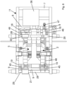
Figure 2 is a top view of the machine inFigure 1 ; -
Figure 2a is a top view of a variant of the machine inFigure 1 ; -
Figure 3 is a bottom view of the machine inFigure 1 ; -
Figure 4 is a cross-section view taken along a plane A-A of the machine inFigure 2 ; -
Figure 5 is a cross-section view taken along a plane B-B of the machine inFigure 2 ; -
Figure 6 is a first side view of the machine inFigure 1 ; -
Figure 7 is a perspective view of a second embodiment of the welding machine according to the invention; -
Figure 8 is a top view of a further variant of the welding machine according to the invention; -
Figure 9 is a perspective bottom view of said further variant inFigure 8 . - The same reference numbers and letters in the figures refer to the same elements or components.
- Some examples of a welding machine of the flash butt welding type according to the invention are illustrated with reference to the Figures.
- In all the embodiments of the invention, the welding machine, which is suitable for welding the tail of a first longitudinal metal product to the head of a second longitudinal metal product along a feeding direction X of said longitudinal metal products, comprises a
carriage 1, adapted to slide on at least twosliding guides - The
carriage 1 supports: - a
first structure 2 connected to thecarriage 1 ; - first clamping means 3, 4, provided on the
first structure 2, for clamping the tail of the first metal product or the head of the second metal product; - a
second structure 5 sliding, relative to both thefirst structure 2 and thecarriage 1, parallel to the feeding direction X; - second clamping means 6, 7, provided on the
second structure 5, for clamping the head of the second metal product or the tail of the first metal product; - at least one
transformer 36 provided withconductors - In a first embodiment, shown in
Figures 1-6 , thefirst structure 2 defines a longitudinal axis Z (Figure 1 ), inclined relative to a horizontal plane, by an acute angle, preferably between 30° and 70°, e.g. 45°. Thesecond structure 5, defining an own longitudinal axis Z' parallel to the longitudinal axis Z (Figure 1 ), is arranged substantially parallel to thefirst structure 2 and spaced from the latter along the feeding direction X of the products to be welded. - In a variant (not shown), instead, the
first structure 2 and thesecond structure 5, substantially parallel to each other, define a respective longitudinal axis arranged substantially horizontally. - At least one infeed guide and at least one outfeed guide are optionally provided for the infeed and outfeed of metal products from the welding machine, each guide being constrained to a
respective structure carriage 1. - Preferably, both the first clamping means 3, 4 and the second clamping means 6, 7 are possibly adjustable in position by means of respective moving
systems first structure 2 and on thesecond structure 5, respectively (Figure 2 and3 ). Such moving systems comprise, for example, hydraulic cylinders or jacks, or electric actuators or mechanical moving devices, such as cam or eccentric devices. - In particular, the first clamping means 3, 4 of the
first structure 2 comprise a respectiveupper clamp 3 and a respectivelower clamp 4. Eachclamp system 41, 42 (Figures 2 and3 ). - The second clamping means 6, 7 of the
second structure 5 comprise a respectiveupper clamp 6 and a respectivelower clamp 7. Once again, eachclamp system 43, 44 (Figures 2 and3 ). - The movement, and therefore the adjustability, of all the clamps of the clamping means advantageously eliminates the need to have to incline or rotate slightly the two
structures - Advantageously, the
first structure 2 and thesecond structure 5 are supported, and possibly also contained, in afirst part 10 of thecarriage 1 delimited by afirst beam 9 and asecond beam 8 of the carriage that are parallel to each other and to the feeding direction X, while the at least onetransformer 36 is fixed to thecarriage 1 and supported, and possibly also contained, entirely in asecond part 11 of thecarriage 1, arranged laterally outside thefirst part 10. Thetransformer 36 can be a single transformer. Alternatively, a group of transformers can be provided which concur to electrically supply theclamps conductors - In a variant (not shown) of this first embodiment, there are, instead, provided two or more transformers fixed to the
carriage 1 and supported, and possibly also contained, entirely in saidsecond part 11. - In this first embodiment of the invention, the
second part 11 of thecarriage 1 can be delimited by saidsecond beam 8 and athird beam 7 of thecarriage 1, preferably parallel to thesecond beam 8. Thefirst beam 9 and thethird beam 7 are peripheral beams of thecarriage 1 while thesecond beam 8 is an intermediate beam. At least two further peripheral beams, which are transverse, preferably perpendicular, to thebeams carriage 1 together with thebeams - The
carriage 1 is preferably arranged on two slidingguides Figure 2 , thefirst beam 9 and thesecond beam 8 of thecarriage 1 are positioned at a respective slidingguide first part 10 of thecarriage 1 is above and at an area delimited by the sliding guides 20, 30. Instead, in the variant ofFigure 2a , thesecond beam 8 is positioned at the slidingguide 30, while thethird beam 7 is positioned at the slidingguide 20. In this case, thesecond part 11 of thecarriage 1 is above and at the area delimited by the sliding guides 20, 30. - Alternatively, the
beams beams - Optionally, the
conductors transformer 36 to the first clamping means 3, 4 and to the second clamping means 6, 7, respectively, passing underneath thefirst structure 2 and thesecond structure 5, respectively, in order to leave both the space between the first clamping means 3, 4 and the space between the second clamping means 6, 7 freely accessible from below in the absence of longitudinal metal products to be welded. - Preferably, as better illustrated in
Figures 2 ,3 and5, 6 , theupper conductors transformer 36 can advance parallel to each other by passing for a small stretch respectively below thefirst structure 2 and thesecond structure 5 until arriving in proximity of the respectiveupper clamps upper clamps - The
lower conductors Figures 3 ,5 and 6 , exiting from thetransformer 36 can advance parallel to each other with a first stretch thereof below thefirst structure 2 and thesecond structure 5, respectively. Before arriving at theupper clamps lower conductors first structure 2 and of thesecond structure 5 with a fourth stretch thereof. A fifth and final stretch of theconductors lower clamps lower clamps lower conductors - Advantageously, since the
transformer 36 is not arranged above thestructures - in the variant (not shown) comprising two or more transformers in the
second part 11 of thecarriage 1, e.g. only two transformers arranged on top of each other, a first upper conductor and a first lower conductor exit the respective transformer and respectively reach theclamps first structure 2; while a second upper conductor and a second lower conductor exit the respective transformer and respectively reach theclamps second structure 5. Also in this case, the pattern of the currents is such that the two circuits close between theupper clamps lower clamps - in all variants, however, the conductors can be arranged in configurations other than those described above, while maintaining free access from below to both the space between the first clamping means 3, 4 and the space between the second clamping means 6, 7, in the absence of the longitudinal metal products to be welded.
- Preferably, the
first structure 2 and thesecond structure 5, in addition to being arranged substantially parallel to each other, are arranged transversely, preferably orthogonally, to thefirst beam 9 and thesecond beam 8. - in particular, in a first variant shown in
Figures 1-7 , thefirst beam 9 and thesecond beam 8 have a respective first portion, proximal to thefirst structure 2 and to which saidfirst structure 2 is integrally fixed, and a respective second portion, distal from thefirst structure 2 and to which thesecond structure 5 is slidingly connected. - In a variant of the invention, the second portion of the
first beam 9 is inserted in a first through-hole 21 of the second structure 5 (Figures 1 and5 ) internally provided with first rolls orpads 12 for a sliding of thesecond structure 5 on thefirst beam 9; and the second portion of thesecond beam 8 is inserted in a second through-hole 22 of the second structure 5 (Figure 5 ) provided internally with second rolls orpads 13 for a sliding of thesecond structure 5 on thesecond beam 8. - Preferably, both the second portion of the
first beam 9 and the first through-hole 21 have a quadrangular cross-section, and said first through-hole 21 is provided with first rolls orpads 12 only on two mutually opposite inner sides (Figure 5 ), preferably above and below thefirst beam 9. Optionally, a pair offirst rolls 12 is provided on each of said two inner sides (Figure 4 ). Also the second portion of thesecond beam 8 and the second through-hole 22 can have a quadrangular section, and said second through-hole 22 is provided with at least one second roll orpad 13 on at least three of its inner sides. In particular, in the variant ofFigure 5 , four rolls orpads 13 are provided, one on each of the inner sides of the through-hole 22. Instead, in a variant (not shown) only three rolls orpads 13 are provided, one upper roll at the upper inner side of the through-hole 22, thus above thebeam 8, and the other two rolls at the sides of thebeam 8. Therefore, there is no lower roll or pad which, if present, results in better alignment. - In a particular variant, the first rolls 12 are idle, accommodated in respective seats obtained in the
second structure 5 and protruding into the first through-hole 21 to come into contact with mutually opposite surfaces of thefirst beam 9; and also the second rolls 13 are idle, accommodated in respective seats obtained in thesecond structure 5 and protruding into the second through-hole 22 to come into contact with the respective side surface of thesecond beam 8. - Alternatively to the quadrangular sections of
beams holes first beam 9 and the first through-hole 21 have a round section, and said first through-hole 21 is provided withfirst pads 12; and both the second portion of thesecond beam 8 and the second through-hole 22 have a round section and said second through-hole 22 is provided withsecond pads 13. - Furthermore, the sliding of the
second structure 5 on thebeams holes hole 21 of thesecond structure 5 can be internally provided with at least three rolls orpads 13 for a sliding of thesecond structure 5 on thefirst beam 9; and the second through-hole 22 of thesecond structure 5 can be internally provided with second rolls orpads 12, only on two internal sides opposite to each other, for a sliding of thesecond structure 5 on thesecond beam 8. - Should it be necessary or desired to move the two
structures Figures 8 and9 , provides that thefirst structure 2 and thesecond structure 5 are supported in thefirst part 10 of thecarriage 1 not by means of thebeams first structure 2 and saidsecond structure 5 together with respect to thecarriage 1, by means of a rotation along a plane which is transverse to the feeding direction X. Such a rotation can be in the range of 1° to 25°, e.g. 1° to 15°. Thus, this lifting system makes it possible to move thestructures - Said lifting system, preferably of the linkage type, comprises:
- a first
rotating shaft 19, parallel and proximal to thefirst beam 9 of the carriage, and constrained to the carriage so as to rotate about an axis thereof, e.g. pivoted at its ends to the carriage peripheral beams which are transverse to the feeding direction X; - a second
rotating shaft 18, parallel and proximal to thesecond beam 8 of the carriage, and constrained to the carriage so as to rotate about an axis thereof, e.g. pivoted at its ends to said transverse peripheral beams; - a further
first beam 29, distinct from the carriage, parallel, proximal and possibly placed above said first rotatingshaft 19 and saidfirst beam 9; - a further
second beam 28, distinct from the carriage, parallel, proximal and possibly placed above said secondrotating shaft 18 and saidsecond beam 8; - at least one
first lever 45 connecting, either directly or indirectly, the firstrotating shaft 19 to said furtherfirst beam 29; - at least one
second lever 46 connecting, either directly or indirectly, the secondrotating shaft 18 to said furthersecond beam 28; - preferably at least one connecting rod or
tie rod 48 connecting firstrotating shaft 19 and secondrotating shaft 18. - in a variant, the longitudinal axes of the first
rotating shaft 19 and the secondrotating shaft 18 are parallel and arranged on a first horizontal plane. The longitudinal axes of the furtherfirst beam 29 and the furthersecond beam 28 are also parallel and arranged on a second horizontal plane, located above the first horizontal plane. The relative position between eachrotating shaft further beam levers - Preferably, the following are provided (
Figure 8 ): - two
first levers 45, each fixed to at a first end thereof to a respective end of the firstrotating shaft 19, and connected, directly or indirectly, at a second end thereof to a respective end of the furtherfirst beam 29; - two
second levers 46, each fixed at a first end thereof to a respective end of the secondrotating shaft 18, and connected, directly or indirectly, at a second end thereof to a respective end of the furthersecond beam 28. - The further
first beam 29 and the furthersecond beam 28 support both thefirst structure 2 and thesecond structure 5, which are arranged substantially parallel to each other and transversely, preferably orthogonally, to said furtherfirst beam 29 and said furthersecond beam 28. - At least one
actuator 47 is provided, adapted to rotate the firstrotating shaft 19 and/or the secondrotating shaft 18 by a predetermined angle so that thefirst structure 2 and thesecond structure 5 can be lifted together with respect to thecarriage 1. - Preferably, in the variant of
Figures 8-9 , only oneactuator 47 is provided, e.g. fixed on thebeam 8 of thecarriage 1, which acts on afurther lever 49 of the secondrotating shaft 18. - Starting from the resting position (
Figure 9 ), theactuator 47 pushes thelever 49 downwards causing the rotatingshaft 18 to rotate by a predetermined angle, about own axis, and to transmit, by means oflevers 46, the upward rotation to thefurther beam 28. Since thefurther beam 28 and thefurther beam 29 together transversely support both thestructure 2 and thestructure 5, the upward rotation is also transmitted to thefurther beam 29 and, therefore, the rotatingshaft 19 also accordingly rotates about its axis. Preferably, a connecting rod ortie rod 48 can synchronize the rotations of the tworotating shafts further beams - In particular, the further
first beam 29 and said furthersecond beam 28 have a respective first portion, which is proximal to thefirst structure 2 and to which saidfirst structure 2 is integrally fixed, and a respective second portion, which is distal from thefirst structure 2 and to which thesecond structure 5 is slidingly connected. - In a variant of the invention, the second portion of the further
first beam 29 is inserted into a first through-hole 21 of thesecond structure 5, internally provided with first rolls or pads for a sliding of thesecond structure 5 on said furtherfirst beam 29; and the second portion of the furthersecond beam 28 is inserted into a second through-hole 22 of thesecond structure 5, internally provided with second rolls or pads for a sliding of thesecond structure 5 on said furthersecond beam 28. - Preferably, both the second portion of the further
first beam 29 and the first through-hole 21 have a quadrangular cross-section, and said first through-hole 21 is provided with first rolls or pads only on two inner sides opposite to each other (in a manner similar toFigure 5 ), preferably above and below thebeam 29. Optionally, a pair of first rolls is provided on each of said two inner sides (in a manner similar toFigure 4 ). Also the second portion of the furthersecond beam 28 and the second through-hole 22 can have a quadrangular section and said second through-hole 22 is provided with at least one second roll or pad on at least three of its inner sides. In particular, in a variant (in a manner similar toFigure 5 ), four second rolls or pads are provided, one on each of the inner sides of the through-hole 22. in a further variant, instead, only three second rolls or pads are provided, one upper roll at the upper inner side of the through-hole 22, therefore above thebeam 28, and the other two rolls at the sides of thebeam 28. Therefore, there is no lower roll or pad which, if present, results in better alignment. - In a particular variant, the first rolls are idle, accommodated in respective seats obtained in the
second structure 5 and protruding into the first through-hole 21 to come into contact with mutually opposite surfaces of the furtherfirst beam 29; and also the second rolls are idle, accommodated in respective seats in thesecond structure 5 and protruding into the second through-hole 22 to come into contact with the respective side surface of the furthersecond beam 28. - Alternatively to the quadrangular sections of the
further beams holes first beam 29 and the first through-hole 21 have a round section, and said first through-hole 21 is provided with first pads; and both the second portion of the furthersecond beam 28 and the second through-hole 22 have a round section and said second through-hole 22 is provided with second pads. - Furthermore, the sliding of the
second structure 5 on thefurther beams holes hole 21 of thesecond structure 5 can be internally provided with at least three second rolls or pads for a sliding of thesecond structure 5 on the furtherfirst beam 9; and the second through-hole 22 of thesecond structure 5 can be internally provided with first rolls or pads, only on two internal sides opposite to each other, for a sliding of thesecond structure 5 on the furthersecond beam 28. - A further advantage of the invention can be that of making the
carriage 1 provided with at least onemotor 31 connected to atoothed wheel 32 adapted to engage arack 33 provided on at least one of the sliding guides 20, 30 (Figure 6 ), preferably on one of the sides of the sliding guide. - In the welding machine of the invention, adjustment means 23, 24 can be provided for moving the
second structure 5 towards or away from thefirst structure 2 along said feeding direction X. The approaching is made, in particular, when welding two products by flash welding. - Optionally, said adjustment means are upsetting
cylinders - The upsetting
cylinders first structure 2 and at a second end thereof to thesecond structure 5 by means of respective pins. - In the variant shown in
Figure 5 , a first upsettingcylinder 23 is arranged inferiorly behind both thefirst structure 2 and thesecond structure 5. In contrast, the second upsettingcylinder 24 is arranged substantially at the feet of both thefirst structure 2 and thesecond structure 5. Preferably the two upsettingcylinders - A second embodiment of the welding machine of the invention is shown in
Figure 7 . The description provided above for the first embodiment also applies to this second embodiment. The latter differs from the first embodiment in that it provides for: - a
first transformer 36 fixed to thecarriage 1 and supported, and possibly also contained, entirely in thesecond part 11 of thecarriage 1, arranged laterally outside thefirst part 10 delimited by thefirst beam 9 and thesecond beam 8; - and a second transformer 36' fixed to the
carriage 1 and supported, and possibly also contained, in a third part 11' of thecarriage 1 arranged laterally outside thefirst part 10, in an opposite way to thesecond part 11. - The
first part 10 of thecarriage 1 is delimited by thefirst beam 9 and by thesecond beam 8 of thecarriage 1, which are parallel to the feeding direction X. - The
second part 11 of thecarriage 1 is delimited by saidsecond beam 8 and by athird beam 7 of thecarriage 1, preferably parallel to thesecond beam 8. - The third part 11' of the
carriage 1 is delimited by saidfirst beam 9 and by a fourth beam 7', preferably parallel to thefirst beam 9. - The fourth beam 7' and the
third beam 7 are peripheral beams of thecarriage 1 while thefirst beam 9 and thesecond beam 8 are intermediate beams of the carriage. - At least two further peripheral beams, which are transverse, preferably perpendicular, to the
beams carriage 1 together with thebeams 7' and 7. - In this second embodiment, an
upper conductor 37 and alower conductor 39 exit thefirst transformer 36 and reach theupper clamps structures upper conductor 40 and alower conductor 38 exit the second transformer 36' and reach thelower clamps structures upper clamps lower clamps - A third embodiment of the welding machine of the invention (not shown) differs from the aforementioned second embodiment in that it provides:
- the
first structure 2 defining a longitudinal axis Z inclined with respect to a horizontal plane, by an acute angle, preferably between 30° and 70°, e.g. 45°; - and the
second structure 5 defining a longitudinal axis Z' thereof which is skew with respect to the longitudinal axis Z and inclined with respect to the aforesaid horizontal plane by an obtuse angle, preferably comprised between 120° and 160°, e.g. 135°. - The
second structure 5 is arranged substantially parallel to thefirst structure 2 and spaced therefrom along the feeding direction X of the products to be welded.
Claims (19)
- A welding machine, preferably of the flash welding type, to weld the tail of a first longitudinal metal product together with the head of a second longitudinal metal product along a feeding direction (X) of said longitudinal metal products, the machine comprising a carriage (1) adapted to slide along the feeding direction (X), said carriage (1) supporting- a first structure (2) connected to said carriage (1);- first clamping means (3, 4), provided on said first structure (2), to clamp either the tail of the first metal product or the head of the second metal product;- a second structure (5) adapted to slide, with respect to both the first structure (2) and the carriage (1), parallel to the feeding direction;- second clamping means (6, 7), provided on said second structure (5), to clamp either the head of the second metal product or the tail of the first metal product;- at least one transformer (36) provided with conductors (37, 38, 39, 40) connected to the first clamping means (3, 4) and to the second clamping means (6, 7), respectively, to supply electric current to said tail and said head;characterized in that the first structure (2) and the second structure (5) are supported in a first part (10) of the carriage (1) delimited by a first beam (9) and a second beam (8) of the carriage (1) that are parallel to the feeding direction (X), while the at least one transformer (36) is fixed to the carriage (1) and supported in a second part (11) of the carriage (1), arranged laterally outside the first part (10).
- A welding machine according to claim 1, wherein only one transformer (36) or two or more transformers completely supported in said second part (11) of the carriage (1) are provided; or wherein at least two transformers are provided, a first transformer (36) of said two transformers being fixed to the carriage (1) and supported in said second part (11) of the carriage (1), and a second transformer (36') of said two transformers being fixed to the carriage (1) and supported in a third part (11') of the carriage (1) arranged laterally outside the first part (10), on a side opposite to the second part (11).
- A welding machine according to claim 1 or 2, wherein said second part (11) is delimited by said second beam (8) and by a third beam (7) of the carriage (1), preferably parallel to the feeding direction (X).
- A welding machine according to claim 3, wherein, in the case of only one transformer (36) or two transformers completely supported in the second part (11), the first beam (9) and the third beam (7) are peripheral beams of the carriage (1), while the second beam (8) is an intermediate beam; or wherein, in the case of a first transformer (36) supported in the second part (11) and a second transformer (36') supported in the third part (11') of the carriage (1), said third part (11') is delimited by said first beam (9) and a fourth beam (7'), the fourth beam (7') and the third beam (7) being peripheral beams of the carriage (1), while the first beam (9) and the second beam (8) are intermediate beams of the carriage.
- A welding machine according to any one of the preceding claims, wherein the conductors (37, 38, 39, 40) connect the at least one transformer (36) to the first clamping means (3, 4) and to the second clamping means (6, 7), respectively, passing underneath the first structure (2) and the second structure (5), respectively, so as to have both the space between the first clamping means (3, 4) and the space between the second clamping means (6, 7) freely accessible from below in the absence of longitudinal metal products to be welded.
- A welding machine according to any one of the preceding claims, wherein both the space between the first clamping means (3, 4) and the space between the second clamping means (6, 7) are freely accessible both from above and below in the absence of longitudinal metal products to be welded.
- A welding machine according to claim 1, wherein the first structure (2) and the second structure (5) are arranged substantially parallel to each other and transversely, preferably orthogonally, to the first beam (9) and the second beam (8).
- A welding machine according to claim 7, in which the first structure (2) and the second structure (5) define a respective longitudinal axis (Z, Z') inclined, with respect to a horizontal plane, by an acute angle between 30° and 70°; or wherein the first structure (2) and the second structure (5) define a respective longitudinal axis arranged substantially horizontally.
- A welding machine according to claim 1 or 7 or 8, wherein the first structure (2) and the second structure (5) are supported in the first part (10) of the carriage (1) by means of a lifting system adapted to lift together said first structure (2) and said second structure (5) with respect to the carriage (1), by means of a rotation along a plane transverse to said feeding direction (X).
- A welding machine according to claim 9, wherein said lifting system is of the linkage type;preferably wherein said lifting system comprises- a first rotating shaft (19), parallel and proximal to the first beam (9) of the carriage and constrained to the carriage so as to rotate about an axis thereof;- a second rotating shaft (18), parallel and proximal to the second beam (8) of the carriage and constrained to the carriage so as to rotate about an axis thereof;- a further first beam (29), distinct from the carriage, parallel, proximal and possibly placed above said first rotating shaft (19) and said first beam (9);- a further second beam (28), distinct from the carriage, parallel, proximal and possibly placed above said second rotating shaft (18) and said second beam (8);wherein the further first beam (29) and the further second beam (28) support both the first structure (2) and the second structure (5), which are arranged substantially parallel to each other and transversely, preferably orthogonally, to said further first beam (29) and said further second beam (28);wherein the first rotating shaft (19) is, directly or indirectly, connected to said further first beam (29) by means of at least one first lever (45);wherein the second rotating shaft (18) is connected, directly or indirectly, to said further second beam (28) by means of at least one second lever (46);and wherein at least one actuator (47) is provided, adapted to rotate the first rotating shaft (19) and/or the second rotating shaft (18) by a predetermined angle so that the first structure (2) and second structure (5) can be lifted together with respect to the carriage (1).
- A welding machine according to claim 10, wherein said further first beam (29) and said further second beam (28) have a respective first portion, which is proximal to the first structure (2) and to which said first structure (2) is integrally fixed, and a respective second portion, which is distal from the first structure (2) and to which the second structure (5) is slidingly connected.
- A welding machine according to claim 1 or 7 or 8, wherein the first structure (2) and the second structure (5) are supported in the first part (10) of the carriage (1), preferably directly, by means of the first beam (9) and the second beam (8) of the carriage (1) that have a respective first portion, which is proximal to the first structure (2) and to which said first structure (2) is integrally fixed, and a respective second portion, which is distal from the first structure (2) and to which the second structure (5) is slidingly connected.
- A welding machine according to claim 11 or 12, wherein the second portion of the further first beam (29) or of the first beam (9) is inserted into a first through-hole (21) of the second structure (5), internally provided with first rolls or pads (12) for the second structure (5) to slide on said further first beam (29) or first beam (9); and wherein the second portion of the further second beam (28) or second beam (8) is inserted into a second through-hole (22) of the second structure (5), internally provided with second rolls or pads (13) for the second structure (5) to slide on said further second beam (28) or second beam (8).
- A welding machine according to claim 13, wherein both the second portion of the further first beam (29), or of the first beam (9), and the first through-hole (21) have a quadrangular section, and said first through-hole (21) is provided with the first rolls or pads (12) on two opposite inner sides only, preferably wherein a pair of first rolls (12) is provided on each of said two inner sides; and wherein both the second portion of the further second beam (28), or the second beam (8), and the second through-hole (22) have a quadrangular section, and said second through-hole (22) is provided with at least a second roll or pad (13) on at least three of the inner sides thereof;
or wherein both the second portion of the further first beam (29), or of the first beam (9), and the first through-hole (21) have a round section, and said first through-hole (21) is provided with the first pads (12); and wherein both the second portion of the further second beam (28), or of the second beam (8), and the second through-hole (22) have a round section, and said second through-hole (22) is provided with the second pads (13). - A welding machine according to claim 14, wherein the first rolls (12) are idle accommodated in respective seats obtained in the second structure (5) and protruding into the first through-hole (21) to come into contact with mutually opposite surfaces of the further first beam (29) or of the first beam (9); and wherein the second rolls (13) are idle, accommodated in respective seats obtained in the second structure (5) and protruding into the second through-hole (22) to come into contact with the respective side surface of the further second beam (28) or of the second beam (8).
- A welding machine according to any one of the preceding claims, wherein the carriage (1) is adapted to slide on at least two sliding guides (20, 30) along the feeding direction (X), and is provided with at least one motor (31) connected to a toothed wheel (32) adapted to be meshed with a rack (33) provided on at least one of the sliding guides (20, 30).
- A welding machine according to any one of the preceding claims, wherein adjustment means (23, 24) are provided for moving the second structure (5) towards or away from the first structure (2) along said feeding direction (X).
- A welding machine according to any one of the preceding claims, wherein both the first clamping means (3, 4) and the second clamping means (6, 7) are positionally adjustable by means of respective moving systems (41, 42; 43, 44) provided on the first structure (2) and on the second structure (5), respectively.
- A welding machine according to any one of the preceding claims, wherein all components of the machine subject to maintenance are accessible and can be lifted from above.
Applications Claiming Priority (2)
| Application Number | Priority Date | Filing Date | Title |
|---|---|---|---|
| IT202000002020 | 2020-02-03 | ||
| PCT/IB2021/050822 WO2021156738A1 (en) | 2020-02-03 | 2021-02-02 | Welding machine |
Publications (3)
| Publication Number | Publication Date |
|---|---|
| EP4100179A1 EP4100179A1 (en) | 2022-12-14 |
| EP4100179C0 EP4100179C0 (en) | 2024-04-03 |
| EP4100179B1 true EP4100179B1 (en) | 2024-04-03 |
Family
ID=70480493
Family Applications (1)
| Application Number | Title | Priority Date | Filing Date |
|---|---|---|---|
| EP21708070.4A Active EP4100179B1 (en) | 2020-02-03 | 2021-02-02 | Welding machine |
Country Status (7)
| Country | Link |
|---|---|
| US (1) | US12397366B2 (en) |
| EP (1) | EP4100179B1 (en) |
| JP (1) | JP7457136B2 (en) |
| CN (1) | CN115297975B (en) |
| ES (1) | ES2980908T3 (en) |
| PL (1) | PL4100179T3 (en) |
| WO (1) | WO2021156738A1 (en) |
Families Citing this family (4)
| Publication number | Priority date | Publication date | Assignee | Title |
|---|---|---|---|---|
| IT202200013807A1 (en) * | 2022-06-30 | 2023-12-30 | Danieli Off Mecc | WELDING MACHINE |
| EP4335562A1 (en) * | 2022-09-08 | 2024-03-13 | David Teng Pong | Flash welding for billets with down cut billet ends |
| EP4559613A1 (en) | 2023-11-22 | 2025-05-28 | SMS group S.p.A. | Welding machine for longitudinal metal objects, in particular billets |
| CN119772475B (en) * | 2025-03-11 | 2025-06-17 | 国网山东省电力公司平原县供电公司 | A rotary welding machine for producing electric iron accessories |
Citations (2)
| Publication number | Priority date | Publication date | Assignee | Title |
|---|---|---|---|---|
| EP1065013A1 (en) | 1999-06-30 | 2001-01-03 | TECHINT COMPAGNIA TECNICA INTERNAZIONALE S.p.A. | Method and plant for the rolling of a continuous billet fed from a billet-heating furnace set upstream of a roll train |
| JP2003019502A (en) | 2001-07-02 | 2003-01-21 | Nkk Corp | Continuous rolling method and equipment |
Family Cites Families (22)
| Publication number | Priority date | Publication date | Assignee | Title |
|---|---|---|---|---|
| DE1003371B (en) * | 1955-04-09 | 1957-02-28 | Siemens Ag | Device for welding together rolling stock to form an endless strand within a continuous rolling mill by means of flash welding |
| JPS5357154A (en) * | 1976-11-02 | 1978-05-24 | Ishikawajima Harima Heavy Ind | Electrifyng method and apparatus for butt welder* |
| JPS5648463Y2 (en) * | 1978-06-09 | 1981-11-12 | ||
| JPS591153B2 (en) * | 1979-07-09 | 1984-01-10 | 三菱電機株式会社 | Flash welding equipment |
| JPS59194379U (en) * | 1983-06-10 | 1984-12-24 | 大阪電気株式会社 | Flash butt welding equipment |
| JPS6130287A (en) * | 1984-07-19 | 1986-02-12 | Mitsubishi Electric Corp | Flash welding device |
| JPH082502B2 (en) * | 1990-06-06 | 1996-01-17 | 三菱電機株式会社 | Strip connection device |
| DE59304608D1 (en) * | 1992-11-09 | 1997-01-09 | Schlatter Ag | Flash butt welding machine |
| JP3042379B2 (en) * | 1995-08-31 | 2000-05-15 | 日本鋼管株式会社 | HDR continuous rolling method |
| FR2836849B1 (en) * | 2002-03-05 | 2004-11-26 | Vai Clecim | METHOD AND DEVICE FOR CONTROLLING THE SPARK WELDING OF TWO METAL PARTS |
| US9931718B2 (en) * | 2008-07-11 | 2018-04-03 | Primetals Technologies Japan, Ltd. | Metal plate joining method and apparatus |
| AT515525B1 (en) * | 2014-07-28 | 2015-10-15 | Plasser & Theurer Export Von Bahnbaumaschinen Gmbh | welding unit |
| AT518501B1 (en) * | 2016-03-02 | 2018-07-15 | Plasser & Theurer Export Von Bahnbaumaschinen Gmbh | Welding unit and method for welding rails of a track |
| AT15368U1 (en) * | 2016-04-01 | 2017-07-15 | Plasser & Theurer Export Von Bahnbaumaschinen Gmbh | Welding unit for welding two rails of a track |
| IT201600092574A1 (en) * | 2016-09-14 | 2018-03-14 | Danieli Off Mecc | PROTECTION DEVICE FOR WELDING SPRAYS WITH INTEGRATED CLEANING SYSTEM |
| AT520125B1 (en) * | 2017-07-04 | 2019-04-15 | Plasser & Theurer Export Von Bahnbaumaschinen Gmbh | Device for welding a rail joint of a track |
| IT201800006117A1 (en) * | 2018-06-07 | 2019-12-07 | LAMINATION PLANT FOR METALLIC PRODUCTS | |
| CN209532395U (en) * | 2019-01-25 | 2019-10-25 | 广州市火龙焊接设备有限公司 | A kind of flash butt welder |
| AT522860B1 (en) * | 2019-07-31 | 2023-05-15 | Plasser & Theurer Export Von Bahnbaumaschinen Gmbh | Welding unit for welding rails of a track |
| IT201900019750A1 (en) * | 2019-10-24 | 2021-04-24 | Danieli Off Mecc | WELDING MACHINE AND RELATIVE METHOD |
| EP4526073A1 (en) * | 2022-05-20 | 2025-03-26 | WIKUS-Sägenfabrik Wilhelm H. Kullmann GmbH & Co. KG | Band flash butt welding machine and group of accessories for a band flash butt welding machine |
| EP4559613A1 (en) * | 2023-11-22 | 2025-05-28 | SMS group S.p.A. | Welding machine for longitudinal metal objects, in particular billets |
-
2021
- 2021-02-02 EP EP21708070.4A patent/EP4100179B1/en active Active
- 2021-02-02 CN CN202180012351.2A patent/CN115297975B/en active Active
- 2021-02-02 WO PCT/IB2021/050822 patent/WO2021156738A1/en not_active Ceased
- 2021-02-02 PL PL21708070.4T patent/PL4100179T3/en unknown
- 2021-02-02 JP JP2022545450A patent/JP7457136B2/en active Active
- 2021-02-02 ES ES21708070T patent/ES2980908T3/en active Active
- 2021-02-02 US US17/759,214 patent/US12397366B2/en active Active
Patent Citations (2)
| Publication number | Priority date | Publication date | Assignee | Title |
|---|---|---|---|---|
| EP1065013A1 (en) | 1999-06-30 | 2001-01-03 | TECHINT COMPAGNIA TECNICA INTERNAZIONALE S.p.A. | Method and plant for the rolling of a continuous billet fed from a billet-heating furnace set upstream of a roll train |
| JP2003019502A (en) | 2001-07-02 | 2003-01-21 | Nkk Corp | Continuous rolling method and equipment |
Non-Patent Citations (9)
| Title |
|---|
| A SCREEN SHOT OF THE WEBPAGE OF THE ONLINE UNIVERSITY BOOKSTORE "UNILIBRO" SHOWING THE ENTRY FOR THE ABOVE-MENTIONED BOOK D2. |
| ANONYMOUS: "PRIMETALS TECHNOLOGIES SUPPLIES ERT-EBROS BILLET WELDING SYSTEM FOR ROLLING MILL OF FERRIERA VALSABBIA", PRIMETALS PRESS RELEASE, XP093253024, Retrieved from the Internet <URL:https://www.primetals.com/press-media/news/primetals-technologies-supplies-ert-ebros-billet-welding-system-for-rolling-mill-of-ferriera-valsabbia> |
| ANONYMOUS: "Primetals Technologies supplies ERT-EBROS billet welding system for Union Iron & Steel rolling mill", PRIMETALS PRESS RELEASE, XP093253020, Retrieved from the Internet <URL:https://www.primetals.com/fileadmin/user_upload/press-releases/2017/20170418/PR2017041273en.pdf> |
| ANONYMOUS: "Primetals Technologies supplies ERT-EBROS billet welding system for Yongfeng Steel bar rolling mill ", PRIMETALS PRESS RELEASE, XP093253018, Retrieved from the Internet <URL:https://www.primetals.com/fileadmin/user_upload/press-releases/2016/20160927/PR2016091183en.pdf> |
| CONFERENCE PRESENTATION BOOKLET FOR THE 28° CONVEGNO NAZIONALE AIM IN MILAN. |
| LAINATI ALBERTO, GIACOMINI LUIGI: "ERT-EBROS BILLET WELDING TECHNOLOGY FOR LONG PRODUCTS ", SEMINÁRIO DE LAMINAÇÃO E CONFORMAÇÃO DE METAIS, PARTE INTEGRANTE DA ABM WEEK, 2 October 2018 (2018-10-02) - 4 October 2018 (2018-10-04), XP093253016 |
| LUIGI ETTORE GIACOMINI: "Proceedings of the Seminar on Rolling, Metal Forming and Products", Retrieved from the Internet <URL:https://abmproceedings.com.br/en/article/ert-ebros-billet-welding-technology-for-long-products> [retrieved on 20240922] |
| PRESENTATION "W.E.R.T. WELDING ENDLESS ROLLING TECHNOLOGY", GIVEN DURING THE 28° CONVEGNO NAZIONALE AIM IN MILANO ON 09.11.2000 |
| VIRGINIO POMETTO ET AL.: "W.E.R.T.- Welding Endless Rolling Technology", II CONVEGNO DEL 2000. 28° CONVEGNO NAZIONALE AIM (MILANO 8-10 NOVEMBRE 2000, AIM, 1 November 2000 (2000-11-01) - 10 November 2000 (2000-11-10), pages 605 - 613, XP009561083, ISBN: 8885298389 |
Also Published As
| Publication number | Publication date |
|---|---|
| US12397366B2 (en) | 2025-08-26 |
| US20230052794A1 (en) | 2023-02-16 |
| PL4100179T3 (en) | 2024-07-29 |
| JP2023511698A (en) | 2023-03-22 |
| EP4100179C0 (en) | 2024-04-03 |
| ES2980908T3 (en) | 2024-10-03 |
| EP4100179A1 (en) | 2022-12-14 |
| JP7457136B2 (en) | 2024-03-27 |
| CN115297975B (en) | 2025-10-10 |
| CN115297975A (en) | 2022-11-04 |
| WO2021156738A1 (en) | 2021-08-12 |
Similar Documents
| Publication | Publication Date | Title |
|---|---|---|
| EP4100179B1 (en) | Welding machine | |
| EP3812055B1 (en) | A welding machine and related method | |
| CN108526226B (en) | Step-by-step cooling bed rolled piece alignment device | |
| WO1993020960A1 (en) | A rolling stand for generic rolling mills having three or more adjustable driven rolls | |
| KR101187221B1 (en) | Device for adjusting the distance of a stripper chisel | |
| JPH10180378A (en) | Lift and clamp device for transfer feeder | |
| CN215236931U (en) | Operation side moving type straightener combined rack | |
| JP3909287B2 (en) | Method for casting and immediately subsequent rolling, and apparatus for supporting, guiding and deforming metal strands, in particular steel strands | |
| KR102551750B1 (en) | roller table device | |
| EP4547414B1 (en) | Welding machine | |
| US5152334A (en) | Guide roll assembly and method of guiding cast strand | |
| US4131154A (en) | Roller apron for a continuous casting installation for steel | |
| KR101204174B1 (en) | Turning machine of long diameter and weighty object | |
| RU2805324C1 (en) | Welding unit | |
| CN117554114A (en) | Multifunctional on-line automatic sampling device and method thereof | |
| CN112756429A (en) | Operation side frame movable type straightener combination frame | |
| JP4161453B2 (en) | Hot material thickness press machine | |
| KR101309981B1 (en) | Slab Turning Apparatus | |
| KR20040059202A (en) | Apparatus for automatic controlling position of slab | |
| JPS6219395Y2 (en) | ||
| EP0274837A1 (en) | Load handling vehicle | |
| JPH06277709A (en) | Universal mill | |
| JP2001001023A (en) | End face aligning device of bar steel and its end face aligning method | |
| ITBS20000038A1 (en) | SERVICE LINE FOR LAMINATES AND EXTRUDED METALLURGICAL AND STEEL PRODUCTS | |
| JPH0259020B2 (en) |
Legal Events
| Date | Code | Title | Description |
|---|---|---|---|
| STAA | Information on the status of an ep patent application or granted ep patent |
Free format text: STATUS: UNKNOWN |
|
| STAA | Information on the status of an ep patent application or granted ep patent |
Free format text: STATUS: THE INTERNATIONAL PUBLICATION HAS BEEN MADE |
|
| PUAI | Public reference made under article 153(3) epc to a published international application that has entered the european phase |
Free format text: ORIGINAL CODE: 0009012 |
|
| STAA | Information on the status of an ep patent application or granted ep patent |
Free format text: STATUS: REQUEST FOR EXAMINATION WAS MADE |
|
| 17P | Request for examination filed |
Effective date: 20220831 |
|
| AK | Designated contracting states |
Kind code of ref document: A1 Designated state(s): AL AT BE BG CH CY CZ DE DK EE ES FI FR GB GR HR HU IE IS IT LI LT LU LV MC MK MT NL NO PL PT RO RS SE SI SK SM TR |
|
| DAV | Request for validation of the european patent (deleted) | ||
| DAX | Request for extension of the european patent (deleted) | ||
| GRAP | Despatch of communication of intention to grant a patent |
Free format text: ORIGINAL CODE: EPIDOSNIGR1 |
|
| STAA | Information on the status of an ep patent application or granted ep patent |
Free format text: STATUS: GRANT OF PATENT IS INTENDED |
|
| INTG | Intention to grant announced |
Effective date: 20230828 |
|
| GRAJ | Information related to disapproval of communication of intention to grant by the applicant or resumption of examination proceedings by the epo deleted |
Free format text: ORIGINAL CODE: EPIDOSDIGR1 |
|
| STAA | Information on the status of an ep patent application or granted ep patent |
Free format text: STATUS: REQUEST FOR EXAMINATION WAS MADE |
|
| GRAP | Despatch of communication of intention to grant a patent |
Free format text: ORIGINAL CODE: EPIDOSNIGR1 |
|
| STAA | Information on the status of an ep patent application or granted ep patent |
Free format text: STATUS: GRANT OF PATENT IS INTENDED |
|
| INTC | Intention to grant announced (deleted) | ||
| INTG | Intention to grant announced |
Effective date: 20231027 |
|
| RIN1 | Information on inventor provided before grant (corrected) |
Inventor name: TOMAT, CLAUDIO Inventor name: PAOLONE, ROLANDO Inventor name: BORDIGNON, GIUSEPPE Inventor name: RUSSIAN, DANIELE |
|
| GRAS | Grant fee paid |
Free format text: ORIGINAL CODE: EPIDOSNIGR3 |
|
| GRAA | (expected) grant |
Free format text: ORIGINAL CODE: 0009210 |
|
| STAA | Information on the status of an ep patent application or granted ep patent |
Free format text: STATUS: THE PATENT HAS BEEN GRANTED |
|
| AK | Designated contracting states |
Kind code of ref document: B1 Designated state(s): AL AT BE BG CH CY CZ DE DK EE ES FI FR GB GR HR HU IE IS IT LI LT LU LV MC MK MT NL NO PL PT RO RS SE SI SK SM TR |
|
| REG | Reference to a national code |
Ref country code: CH Ref legal event code: EP |
|
| REG | Reference to a national code |
Ref country code: DE Ref legal event code: R096 Ref document number: 602021011300 Country of ref document: DE |
|
| REG | Reference to a national code |
Ref country code: IE Ref legal event code: FG4D |
|
| U01 | Request for unitary effect filed |
Effective date: 20240503 |
|
| P04 | Withdrawal of opt-out of the competence of the unified patent court (upc) registered |
Free format text: CASE NUMBER: APP_33397/2024 Effective date: 20240604 |
|
| U07 | Unitary effect registered |
Designated state(s): AT BE BG DE DK EE FI FR IT LT LU LV MT NL PT SE SI Effective date: 20240607 |
|
| REG | Reference to a national code |
Ref country code: ES Ref legal event code: FG2A Ref document number: 2980908 Country of ref document: ES Kind code of ref document: T3 Effective date: 20241003 |
|
| PG25 | Lapsed in a contracting state [announced via postgrant information from national office to epo] |
Ref country code: IS Free format text: LAPSE BECAUSE OF FAILURE TO SUBMIT A TRANSLATION OF THE DESCRIPTION OR TO PAY THE FEE WITHIN THE PRESCRIBED TIME-LIMIT Effective date: 20240803 |
|
| PG25 | Lapsed in a contracting state [announced via postgrant information from national office to epo] |
Ref country code: HR Free format text: LAPSE BECAUSE OF FAILURE TO SUBMIT A TRANSLATION OF THE DESCRIPTION OR TO PAY THE FEE WITHIN THE PRESCRIBED TIME-LIMIT Effective date: 20240403 |
|
| PG25 | Lapsed in a contracting state [announced via postgrant information from national office to epo] |
Ref country code: CZ Free format text: LAPSE BECAUSE OF FAILURE TO SUBMIT A TRANSLATION OF THE DESCRIPTION OR TO PAY THE FEE WITHIN THE PRESCRIBED TIME-LIMIT Effective date: 20240403 |
|
| PG25 | Lapsed in a contracting state [announced via postgrant information from national office to epo] |
Ref country code: NO Free format text: LAPSE BECAUSE OF FAILURE TO SUBMIT A TRANSLATION OF THE DESCRIPTION OR TO PAY THE FEE WITHIN THE PRESCRIBED TIME-LIMIT Effective date: 20240703 Ref country code: IS Free format text: LAPSE BECAUSE OF FAILURE TO SUBMIT A TRANSLATION OF THE DESCRIPTION OR TO PAY THE FEE WITHIN THE PRESCRIBED TIME-LIMIT Effective date: 20240803 Ref country code: HR Free format text: LAPSE BECAUSE OF FAILURE TO SUBMIT A TRANSLATION OF THE DESCRIPTION OR TO PAY THE FEE WITHIN THE PRESCRIBED TIME-LIMIT Effective date: 20240403 Ref country code: CZ Free format text: LAPSE BECAUSE OF FAILURE TO SUBMIT A TRANSLATION OF THE DESCRIPTION OR TO PAY THE FEE WITHIN THE PRESCRIBED TIME-LIMIT Effective date: 20240403 Ref country code: RS Free format text: LAPSE BECAUSE OF FAILURE TO SUBMIT A TRANSLATION OF THE DESCRIPTION OR TO PAY THE FEE WITHIN THE PRESCRIBED TIME-LIMIT Effective date: 20240703 |
|
| REG | Reference to a national code |
Ref country code: DE Ref legal event code: R026 Ref document number: 602021011300 Country of ref document: DE |
|
| PLAZ | Examination of admissibility of opposition: despatch of communication + time limit |
Free format text: ORIGINAL CODE: EPIDOSNOPE2 |
|
| P05 | Withdrawal of opt-out of the competence of the unified patent court (upc) changed |
Free format text: CASE NUMBER: APP_33397/2024 Effective date: 20240607 |
|
| PLBI | Opposition filed |
Free format text: ORIGINAL CODE: 0009260 |
|
| PLBA | Examination of admissibility of opposition: reply received |
Free format text: ORIGINAL CODE: EPIDOSNOPE4 |
|
| PLAB | Opposition data, opponent's data or that of the opponent's representative modified |
Free format text: ORIGINAL CODE: 0009299OPPO |
|
| PLAX | Notice of opposition and request to file observation + time limit sent |
Free format text: ORIGINAL CODE: EPIDOSNOBS2 |
|
| PG25 | Lapsed in a contracting state [announced via postgrant information from national office to epo] |
Ref country code: SK Free format text: LAPSE BECAUSE OF FAILURE TO SUBMIT A TRANSLATION OF THE DESCRIPTION OR TO PAY THE FEE WITHIN THE PRESCRIBED TIME-LIMIT Effective date: 20240403 Ref country code: RO Free format text: LAPSE BECAUSE OF FAILURE TO SUBMIT A TRANSLATION OF THE DESCRIPTION OR TO PAY THE FEE WITHIN THE PRESCRIBED TIME-LIMIT Effective date: 20240403 |
|
| PG25 | Lapsed in a contracting state [announced via postgrant information from national office to epo] |
Ref country code: SM Free format text: LAPSE BECAUSE OF FAILURE TO SUBMIT A TRANSLATION OF THE DESCRIPTION OR TO PAY THE FEE WITHIN THE PRESCRIBED TIME-LIMIT Effective date: 20240403 |
|
| PG25 | Lapsed in a contracting state [announced via postgrant information from national office to epo] |
Ref country code: SM Free format text: LAPSE BECAUSE OF FAILURE TO SUBMIT A TRANSLATION OF THE DESCRIPTION OR TO PAY THE FEE WITHIN THE PRESCRIBED TIME-LIMIT Effective date: 20240403 Ref country code: SK Free format text: LAPSE BECAUSE OF FAILURE TO SUBMIT A TRANSLATION OF THE DESCRIPTION OR TO PAY THE FEE WITHIN THE PRESCRIBED TIME-LIMIT Effective date: 20240403 Ref country code: RO Free format text: LAPSE BECAUSE OF FAILURE TO SUBMIT A TRANSLATION OF THE DESCRIPTION OR TO PAY THE FEE WITHIN THE PRESCRIBED TIME-LIMIT Effective date: 20240403 |
|
| 26 | Opposition filed |
Opponent name: JP STEEL PLANTECH CO. Effective date: 20250103 |
|
| R26 | Opposition filed (corrected) |
Opponent name: JP STEEL PLANTECH CO. Effective date: 20250103 |
|
| U20 | Renewal fee for the european patent with unitary effect paid |
Year of fee payment: 5 Effective date: 20250227 |
|
| PLBB | Reply of patent proprietor to notice(s) of opposition received |
Free format text: ORIGINAL CODE: EPIDOSNOBS3 |
|
| PG25 | Lapsed in a contracting state [announced via postgrant information from national office to epo] |
Ref country code: MC Free format text: LAPSE BECAUSE OF FAILURE TO SUBMIT A TRANSLATION OF THE DESCRIPTION OR TO PAY THE FEE WITHIN THE PRESCRIBED TIME-LIMIT Effective date: 20240403 |
|
| REG | Reference to a national code |
Ref country code: CH Ref legal event code: PL |
|
| PG25 | Lapsed in a contracting state [announced via postgrant information from national office to epo] |
Ref country code: CH Free format text: LAPSE BECAUSE OF NON-PAYMENT OF DUE FEES Effective date: 20250228 |
|
| GBPC | Gb: european patent ceased through non-payment of renewal fee |
Effective date: 20250202 |
|
| PG25 | Lapsed in a contracting state [announced via postgrant information from national office to epo] |
Ref country code: GB Free format text: LAPSE BECAUSE OF NON-PAYMENT OF DUE FEES Effective date: 20250202 |
|
| PG25 | Lapsed in a contracting state [announced via postgrant information from national office to epo] |
Ref country code: IE Free format text: LAPSE BECAUSE OF NON-PAYMENT OF DUE FEES Effective date: 20250202 |
|
| U20 | Renewal fee for the european patent with unitary effect paid |
Year of fee payment: 6 Effective date: 20260227 |
|
| PGFP | Annual fee paid to national office [announced via postgrant information from national office to epo] |
Ref country code: ES Payment date: 20260302 Year of fee payment: 6 |
|
| PGFP | Annual fee paid to national office [announced via postgrant information from national office to epo] |
Ref country code: TR Payment date: 20260127 Year of fee payment: 6 |
|
| PGFP | Annual fee paid to national office [announced via postgrant information from national office to epo] |
Ref country code: PL Payment date: 20260121 Year of fee payment: 6 |