EP4100128B1 - Vorrichtung, system und verfahren zur behandlung von luft während der atmung - Google Patents
Vorrichtung, system und verfahren zur behandlung von luft während der atmung Download PDFInfo
- Publication number
- EP4100128B1 EP4100128B1 EP21711056.8A EP21711056A EP4100128B1 EP 4100128 B1 EP4100128 B1 EP 4100128B1 EP 21711056 A EP21711056 A EP 21711056A EP 4100128 B1 EP4100128 B1 EP 4100128B1
- Authority
- EP
- European Patent Office
- Prior art keywords
- air
- chamber
- mask
- user
- inhalation
- Prior art date
- Legal status (The legal status is an assumption and is not a legal conclusion. Google has not performed a legal analysis and makes no representation as to the accuracy of the status listed.)
- Active
Links
Images


Classifications
-
- A—HUMAN NECESSITIES
- A61—MEDICAL OR VETERINARY SCIENCE; HYGIENE
- A61L—METHODS OR APPARATUS FOR STERILISING MATERIALS OR OBJECTS IN GENERAL; DISINFECTION, STERILISATION OR DEODORISATION OF AIR; CHEMICAL ASPECTS OF BANDAGES, DRESSINGS, ABSORBENT PADS OR SURGICAL ARTICLES; MATERIALS FOR BANDAGES, DRESSINGS, ABSORBENT PADS OR SURGICAL ARTICLES
- A61L9/00—Disinfection, sterilisation or deodorisation of air
- A61L9/16—Disinfection, sterilisation or deodorisation of air using physical phenomena
- A61L9/18—Radiation
- A61L9/20—Ultraviolet radiation
-
- A—HUMAN NECESSITIES
- A62—LIFE-SAVING; FIRE-FIGHTING
- A62B—DEVICES, APPARATUS OR METHODS FOR LIFE-SAVING
- A62B18/00—Breathing masks or helmets, e.g. affording protection against chemical agents or for use at high altitudes or incorporating a pump or compressor for reducing the inhalation effort
- A62B18/006—Breathing masks or helmets, e.g. affording protection against chemical agents or for use at high altitudes or incorporating a pump or compressor for reducing the inhalation effort with pumps for forced ventilation
-
- A—HUMAN NECESSITIES
- A62—LIFE-SAVING; FIRE-FIGHTING
- A62B—DEVICES, APPARATUS OR METHODS FOR LIFE-SAVING
- A62B23/00—Filters for breathing-protection purposes
- A62B23/02—Filters for breathing-protection purposes for respirators
-
- A—HUMAN NECESSITIES
- A62—LIFE-SAVING; FIRE-FIGHTING
- A62B—DEVICES, APPARATUS OR METHODS FOR LIFE-SAVING
- A62B7/00—Respiratory apparatus
- A62B7/10—Respiratory apparatus with filter elements
-
- A—HUMAN NECESSITIES
- A62—LIFE-SAVING; FIRE-FIGHTING
- A62B—DEVICES, APPARATUS OR METHODS FOR LIFE-SAVING
- A62B9/00—Component parts for respiratory or breathing apparatus
- A62B9/006—Indicators or warning devices, e.g. of low pressure, contamination
-
- A—HUMAN NECESSITIES
- A62—LIFE-SAVING; FIRE-FIGHTING
- A62B—DEVICES, APPARATUS OR METHODS FOR LIFE-SAVING
- A62B9/00—Component parts for respiratory or breathing apparatus
- A62B9/02—Valves
Definitions
- a device for enhancing efficiency of an air mask wearable by a user to cover the mouth and nose of the user comprising:
- the device may be retrofitted to a mask to form an integral unit or the chamber may be adapted for attaching to an existing mask, typically but not necessarily via a screw-coupling. It can also be attached using a bayonet coupling or a push-fit snap connection or may be secured using clasps.
- a system according to the invention includes the device with or without an integral mask in combination with auxiliary components as described in detail below.
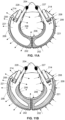
- FIG. 1A illustrates a system 200 according to a first embodiment of the invention comprising a chamber 202 at least indirectly connected to a mask 204 having air openings 205 and 205" shown in Fig. 19 , which serve as an air inlet and an air outlet, respectively.
- a filter element 206 configured to remove viruses and bacteria from either inhaled or exhaled air is mounted in association with the chamber 202.
- the chamber is a right-circular cylinder and the filter element is likewise cylindrical and forms a hollow structure that surrounds an outer wall surface of the chamber.
- the geometry and location of the filter are not crucial so long as the filter is able to filter the air prior to its entering the chamber.
- the filter element 206 has a structure of a typical air filter, namely a particulate air filter, and possibly activated charcoal filter and another particulate filter to trap charcoal dust.
- the filter element 206 may also be formed from other filtering materials adapted to remove viruses and bacteria riding on particles.
- the filter element 206 is two dimensional and attached to the portion of the chamber 202 structure.
- the filter element 206 surrounds the chamber 202 to achieve a significantly larger filter surface area, thus reducing the velocity of air 207 ( FIG. 2 ) over the filter material and thereby significantly increasing the filter efficiency.
- FIGS. 1A and 1B illustrate the system 200 with a UV source 210 exposed to the interior of the chamber 202.
- the UV source 210 is attached to one of the walls of the chamber 202 and is driven by a controller 212 powered by a battery pack 214.
- the controller 212 and the battery pack 214 may be integral with the system 200 or may be separate units that are carried by the user and mechanically and electrically coupled to the system via a suitable connector.
- the controller 212 can either switch the blower 208 and / or UV source 210 ON or OFF or adjust flow rate and power.
- the surfaces of the blades 209 directed to the UV source 210 may also be covered by a UV reflection layer, allowing the blower 208 to reflect most of the direct rays 211 and reflected rays 216 hitting the blower blades 209 ( FIG. 2 ).
- the inlet air blower 208 is configured to provide a relatively low and steady rate of airflow (about 25% only), as it should be lower than the maximum breathing flowrate (400 cc per sec), and therefore the power of the UV source 210 may be dramatically reduced.
- the expandable member 221, previously inflated by the air blower 208 contains a sufficient quantity of already disinfected air and is ready to be deflated, by human inhalation.
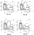
- FIG. 3A illustrates the system 200 with an expandable member 221 at an early stage of exhalation, when the expandable member 221 reaches its minimum volume after being deflated by human inhalation.
- the exhaled air is filtered by the filter layers of the air mask 204, the filter layers being structured to optimize the exhaled air filter.
- FIG. 3B illustrates the system 200 with an expandable member 221 at a final stage of exhalation, when the expandable member 221 has reached its maximum volume.
- Operation of the system illustrated by FIGS. 1 to 4 may be monitored as follows: a) measure the airflow rate using an anemometer 250 ( FIG. 12 and 13A ); b) adjust the UV source 210 power based on the direction and flow rate of the breathing: switch the UV source 210 OFF at exhalation or adjust the UV source 210 power upon inhalation.
- the breathing holes 234 allow the air in the space between the exterior of expandable member 221 and the interior of chamber 202 to be freely discharged in order to maintain the air inside the expandable member 221 at the ambient pressure and to reduce the airflow resistance over the air blower 208 to a minimum.
- FIG. 6 is a detailed cross-section portion view of embodiment of FIG. 5 .
- blower 208 collecting the filtered air from the space in between the filter 206 and chamber 202 and directs this air into the expandable member 221.
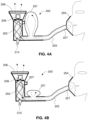
- FIG. 7A illustrates a basic embodiment of a one-way module 201, having an expandable member 221 sealed to the base of a chamber 202, in an inhalation stage.
- a battery 214 is mounted on the exterior of the chamber 202 and connected to a controller 212, which controls the air blower 208, monitors battery voltage and current to the air blower 208 and collects environmental parameters, such as temperature and humidity.
- An RFID reader may be interfaced to the controller 212 to identify the serial numbers of the filter 206 and blower 208 and to send this information via an embedded short-range communication (e.g. blue tooth, WiFi) to a service provider database.
- an embedded short-range communication e.g. blue tooth, WiFi
- the expandable member 221 is attached to the chamber 202 proximate the outer surface of the filter 206. This proximity may allow interconnection between the filter 206 and the expandable member 221, and moreover may allow the functionality of filter 206 and the expandable member 221 to be realized by a single structure, optionally made of the same material of the filter 206. As shown in the FIG. 7A , the exterior of the expandable member 221 is exposed to ambient air, and therefore inhalation via the short flexible pipe 225 should induce negligible pressure drop. By eliminating the pressure drop, the risk of contaminated air leakage of ambient air via the sealing lips of the mask 204 is negligible.
- FIG. 7B illustrates the one-way module 201 of FIG. 7A , during exhalation.
- the filtered air is conveyed by the air blower 208 into the filtered air space captured between the expandable member 221 and the interior of the chamber 202. This space expands during the exhalation stage and reaches its maximum value prior to beginning of the inhalation stage.
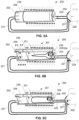
- FIG. 8A illustrates pictorially an embodiment of the one-way module 201 of FIG. 7 , coupled to a two-way mask 204 via a flexible pipe 225.
- FIG. 8B shows a cross-section of the one-way module of FIG. 8A with a sampling module 238 (shown in FIG. 12, 13A and 13B ) located inline the blower 208 airflow.
- the sampling module 238 can be attached to a mount 240 whenever the user or the service provider would like to monitor the system, module or the user's health condition.
- the sampling module 238 is configured to collect particles before or after filtering. When the sampling module 238 is located between the flexible pipe 231 and the exhalation filter 206 ( FIG. 5 ), it will collect evidence of the user's health. When the sampling module 238 is located between the flexible pipe 225 and the inhalation filter 206, it will collect evidence of the performance of the one-way module 201. By attaching the sampling module 238 to the exterior of the filter 206, it will collect evidence of ambient air contamination or infection.
- the sampling module 238 is configured to collect particles on a sampling surface that may be a conventional petri dish ( FIG. 13A ), or by a filter membrane, such as nylon membrane (not shown), glass surface or any other collecting surface or material capable of capturing and retaining the particles.
- a petri dish may capture the particles by its gel agar
- a filter membrane may capture the particles by its structure, glass or other surfaces that allow viruses to survive for a relatively long period, and may capture the particles by moisture condensation taking place in the one-way module during exhalation.
- the aggregated amount of air washing over the sampling module 238 over time, during its operation is significant (typically between 100 to 200 cc per second - at least 2.8 square meter per 8 hours) and therefore the probability of collecting contaminated particles, assuming that such particles are contained in the air, is very high.
- This allows a comprehensive monitoring process to be established on the following parameters: a) level of contamination of the ambient air; b) level of protection provided by the system 200 and its modules 201; c) level of contamination of the exhaled air.
- the sampling module 238 can be configured based on the specific or broad monitoring target. For example, for Covid-19 fast response monitoring the sampling module 238 can be configured as a filter membrane capable of collecting particles of 0.1 micron.
- the sampling module 238 at the exhaled air outlet of the one-way module can provide the medical staff with a health indicator in different departments of hospital and trigger a specific investigation whenever desired.
- the sampling module 238 at the inhaled air inlet of the one-way module can provide a department air quality indicator and trigger a specific investigation, whenever desired.
- the sampling module 238 can be configured as a petri dish.
- the analysis of the sampling module 238 is derived from its configuration: the petri dish can be analyzed based on already well-established techniques. Filter membrane particulate content can be transferred to a liquid or to air by a back-pressure pulse and then be analyzed using known techniques.
- a RFID chip (not shown) may be attached to the sample module 238.
- the pairing between the sampling module 238 and the one-way module 201 may be achieved by an RFID reader onboard the controller 212, or by an external RFID reader that collects the ID of the sampling module 238 and the ID of the one-way module 201 (also by RFID chip), and links both of them to a user and time stamp in the service provider database.
- the chambers 202 are formed with a corrugated outer contour, thus allowing the air blower 208 to convey air between the filter element 206 and an exterior of the chamber 202, via the longitude tunnels created by the corrugations.
- the general profile of the chamber 202 may be elliptical, with a vertical axis shorter than the horizontal axis. The profile may vary in size from a typical shirt collar dimensions, to a neck pillow dimensions, in the extreme.
- the overall surface area of the filter element 206 of collar/pillow shape is at least twice that of any other face mask filter. The increased filter surface area allows for use of a lower power of air blower and provides improved filter performance.
- the temperature of the exhaled air can be measured by a temperature sensor interfaced to the controller 212.
- a portable autoclave may be used (not shown).
- the autoclave may sterilize the system 200 by an external heat source (e.g. home oven), or by an embedded heat element configured to raise and maintain the autoclave temperature to a desired level.
- an external heat source e.g. home oven
- the autoclave walls should be built from highly thermally conductive materials (e.g. aluminum).
- an internal heat source is used, the autoclave walls should be thermally isolated.
- Another internal, broadly available, heat source is hot water that may be boiled and supplied from various water boiling devices.
- FIG. 14 illustrates use of the embodiment of the system of FIGS. 5A to 5C and 8A and 8B .
- the air mask 204 is adapted to be sealed to the user's face by flexible sealing lips stretched on the perimeter of the mask frame.
- One-way valves 227 and 228 have similar functionality to those shown in FIG. 5A to 5C .
- Flexible pipes 225 and 231 create a limited coupling force between the mask 204 and the face.
- the headband 260 stably supports the weight of the one-directional module 201 and system 200 over the user's head.
- a communication membrane 262 may be fitted at the front end of the mask.
- the air mask 204 may have a microphone, interfaced to an external speaker by wires or wirelessly.
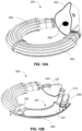
- FIG. 15 illustrates pictorially a detail of the one-way module 201 having a contoured neck rest 270, which sits comfortably against the back of the user's neck while being fluidly coupled to the mask at opposite ends via the expandable pipe 225 and the flexible pipe 231 as best seen in FIGS. 18A and 18B .
- an electronic assembly comprising an ON/OFF switch, microphone socket, speaker and USB port for connection of a battery charger.
- FIG. 16 shows a cross-section view of the one-way module 201 of FIG. 15 .
- the module 201 has same structure and functionality as the module 201 of FIG. 7 .
- a toxic gas absorption charcoal filter 264 may be coupled inline with the blower 208.
- the contact time between the air coming from the filter element 206, and the absorption filter 264 will be significantly longer owing to the low air velocity induced by the blower 208.
- the reduced air velocity allowed by the expandable member 221 facilitates significantly higher disinfection, filtering and absorption efficiencies. As was explained with regard to FIG.
- a typical single structure consists of a cylindrical envelop filter 206 attached by either front or rear lips to lips of the expandable member 221,which may be in general a thin plastic bag of the type typically used for food storage.
- a telescopic link 268 is connected to the flexible pipe 231 and is snap-fitted to a coupling element 266 (shown in FIG. 16 ) on one side of the module 201.
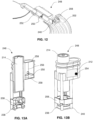
- FIGS. 17A and 17B show a perspective and cross-section views of power and monitoring module 248 according to another embodiment.
- the module 248 incorporates the controller 212, the battery 214, the ON/OFF switch, the USB charger socket, the speaker and the microphone plug.
- the absorption filter 264 is optional and may be coupled by the user to the module 248 prior to being coupled to the module 201.
- FIG. 19 is a rear view of the mask 204.
- Real time monitoring of the system illustrated in any of FIGS. 1 to 15 may be performed as follows: a) actuating the air blowers 208; b) measuring inhalation and exhalation airflows; c) measuring the exhalation and inhalation temperatures; d) sampling the blower current; e) uploading the collected data by Bluetooth TM communication to a user's smartphone; f) uploading the data from the smartphone to a cloud application; e) analyzing the breathing profile of the user and defining the normal breathing flow-temperature profile; and g) looking for deviations and sending the user a message, if such deviation were detected.
- airflow increase may indicate an increase in the demand for higher amount of flow
- airflow decrease may indicate a blocked filter 206 or degradation of lung functionality
- exhalation air temperature increase indicates higher temperature of the user's body
- frequent breathing derived from the airflow measurement, may indicate a general condition of the user and together with the exhalation air temperature more significant indication of user health deviation.
- Advanced monitoring can be achieved by transmitting the module 248 measurements, via the communication link, to a heart rate monitoring device (not shown), such as smart-watch, chest strip, or other, and synchronizing, in real-time, the transmitted data with the heart rate measurements.
- the combined measurements may then be analyzed and displayed to the user (e.g. on the smartphone).
- the analysis of the combined data can provide the user with heart-lung functionality indications in different situations, including sport activities, emergency activities and health monitoring activities.
- the added value of the system with the advance monitoring is dual: protecting the user and providing the user with health indicators. This is extremely important, especially during the pandemic periods, when fast detection of health conditions is required.
- An alternative way is to adapt the system controller 212 to receive, via the communication link, the heart rate measurements from a heart rate monitoring device and to synchronize the measurements onboard the controller 212.
- the measurements can be analyzed and displayed over the user's smartphone and can be uploaded into the service provider's cloud database.
- the surface area of the filter will be a function of the diameter of the chamber and its length.
- the filter can be of the form of a sleeve whose opposing edges formed a closed structure like a donut; but it can also be an open C-shaped structure or it may be spirally wound to form an overlapping structure that functions as a multi-layer structure.
Landscapes
- Health & Medical Sciences (AREA)
- General Health & Medical Sciences (AREA)
- Pulmonology (AREA)
- Business, Economics & Management (AREA)
- Emergency Management (AREA)
- Epidemiology (AREA)
- Life Sciences & Earth Sciences (AREA)
- Animal Behavior & Ethology (AREA)
- Public Health (AREA)
- Veterinary Medicine (AREA)
- Respiratory Apparatuses And Protective Means (AREA)
Claims (15)
- Ein Gerät zur Verbesserung der Effizienz einer Atemschutzmaske (204), die von einem Benutzer getragen wird, um Mund sowie Nase zu bedecken, wobei das Gerät umfasst:eine längliche Kammer (202), die an ihrem proximalen Ende fluidisch mit einer Luftöffnung (205, 205') der Maske (204) verbindbar ist,ein Filterelement (206) aus flexiblem Material, das entweder intern oder extern um die Seitenwand der Kammer gewickelt ist, um Luft, die in beide Richtungen durch die Kammer strömt, zu filtern,ein Einwegventil (227, 228), das in Verbindung mit der Öffnung montiert ist, ein Luftgebläse (208), das so konfiguriert ist, dass es kontinuierlich Luft zur Einatmung bereitstellt oder ausgeatmete Luft abführt,gekennzeichnet dadurch, dass:
ein dehnbares Element (221) fluidisch mit der Kammer verbunden ist:das Einwegventil (227, 228) so konfiguriert ist, dass es behandelte Luft, die vom Benutzer eingeatmet wird, aus der Kammer in die Maske leitet oder ausgeatmete Luft aus der Maske in die Kammer leitet,das dehnbare Element (221) funktionsfähig mit dem Einwegventil verbunden ist, um Luft während der Einatmung oder Ausatmung durch den Filter zu leiten;wobei, wenn die Öffnung als Lufteinlass konfiguriert ist, die Luft während der Einatmung in die Kammer gezwungen ist zu strömen und das dehnbare Element (221) mit behandelter Luft aufzublasen, die zur Einatmung bereitsteht, bevor sie durch die Öffnung in die Lunge des Benutzers strömt; undwenn die Öffnung ein Luftauslass ist, die Luft während der Ausatmung aus der Lunge des Benutzers in die Kammer gezwungen ist zu strömen und das dehnbare Element (221) mit ausgeatmeter Luft aufzublasen, bevor sie als behandelte Luft in die Umgebung abgegeben wird. - Das Gerät nach Anspruch 1, wobei das Filterelement aus einem dünnen Filtermaterial besteht, das gefaltet oder gerollt ist, um eine hohle Struktur mit Öffnungen an gegenüberliegenden Enden zu bilden, und wobei optional eine dieser Öffnungen fluidisch mit einer Öffnung des dehnbaren Elements (221) in einer einheitlichen Konstruktion verbunden ist.
- Das Gerät nach einem der Ansprüche 1 bis 3, wobei das Profil der Kammer so gestaltet und dimensioniert ist, dass sie in den Kragen eines Hemds oder in ein vollständiges Hemd eingefügt werden kann, oder wobei die Kammer als Kanister ausgeführt ist, der mit der Maske durch zwei flexible Schläuche verbunden ist.
- Das Gerät nach einem der vorangehenden Ansprüche, umfassend mindestens eine UV-Quelle, die aus einer Gruppe, bestehend aus Lampen oder LEDs und beliebigen Kombinationen davon, ausgewählt ist, um entweder (i) Luft vor der Einatmung zu reinigen, wenn das Einwegventil so konfiguriert ist, dass gereinigte Luft vom Benutzer aus der Kammer in die Maske geleitet wird, oder (ii) ausgeatmete Luft vor ihrer Freisetzung in die Umgebung zu reinigen, wenn das Einwegventil so konfiguriert ist, dass ausgeatmete Luft aus der Maske in die Kammer erlaubt wird zu strömen.
- Das Gerät nach einem der vorangehenden Ansprüche, wobei das Filterelement so gestaltet ist, dass es am Kopf des Benutzers getragen werden kann.
- Das Gerät nach einem der vorangehenden Ansprüche, wobei das Luftgebläse so konfiguriert ist, dass es die Luft durch die Kammer bewegt und das dehnbare Element mit einem Luftvolumen aufbläst oder entleert, das für mindestens eine Einatmung oder Ausatmung erforderlich ist, oder wobei das Luftgebläse so konfiguriert ist, dass es einen minimalen Luftstrom bereitstellt, der ausreicht, um den Atembedarf zu decken, wodurch die einströmende Luft in die Kammer mit der niedrigstmöglichen Durchflussrate behandelt wird, um die Behandlungseffizienz zu maximieren.
- Das Gerät nach einem der vorangehenden Ansprüche, wobei das dehnbare Element zyklisch für jeden aufeinanderfolgenden Atemzyklus aufgeblasen oder entleert wird.
- Das Gerät nach einem der vorangehenden Ansprüche, wobei das dehnbare Element konfiguriert ist, entweder durch die Ausatmung aufgeblasen zu werden und durch das Luftgebläse entleert zu werden oder durch das Luftgebläse aufgeblasen und durch die Einatmung entleert zu werden.
- Das Gerät nach einem der vorangehenden Ansprüche, wobei das dehnbare Element innerhalb der Kammer angeordnet ist oder an einem äußeren Bereich der Kammer angebracht ist.
- Das Gerät nach einem der vorangehenden Ansprüche, wobei die Kammer eine integrale Einheit mit einer Atemschutzmaske bildet.
- Ein System, umfassend eine Atemschutzmaske, die mit dem Gerät nach einem der vorangehenden Ansprüche verbunden ist, und umfassend ferner mindestens ein Probenahmemodul, das an mindestens einem von der Außen- oder Innenseite des Geräts gekoppelt ist und jeweils so konfiguriert ist, dass es Luftpartikel sammelt, um Beweise für Verunreinigungen oder Infektionen der Umgebungsluft vor der Einatmung zu sammeln oder um Beweise für die Gesundheit des Benutzers nach der Ausatmung zu sammeln.
- Das System nach Anspruch 11, wobei das mindestens eine Probenahmemodul und der Filter eine integrale Einheit bilden.
- Das System nach Anspruch 11 oder 12, wobei:das Luftgebläse (208) so konfiguriert ist, dass es kontinuierlich Luft zur Einatmung liefert und gleichzeitig einen Überdruck innerhalb der Atemschutzmaske erzeugt, undweiterhin ein Controller (212) bereitgestellt ist, der konfiguriert ist, den Motorstrom des Luftgebläses zu messen und die Stromdaten an einen entfernten Computer oder eine zentrale Datenbank weiterzuleiten, um eine gemessene Stromabweichung von einem Schwellenwert als blockierten Filter, Atemzyklus-Stagnationspunkte oder Motorfehlfunktion zu interpretieren.
- Das System nach Anspruch 13, wobei der Controller einen Mikroprozessor und entsprechende Sensoren umfasst, die in der Lage sind, Lufttemperatur, Luftfeuchtigkeit, Atmosphärendruck, Batteriespannung, Gesundheitsstatus, Gebläse-ID, Probenahmemodul-ID, Einatmungsflussrate, Ausatmungsflussrate und Ausatmungslufttemperatur zu erfassen, und optional, wobei der Controller über einen Kommunikationskanal verfügt, der in der Lage ist, mindestens indirekt eine eindeutige ID und die von den Sensoren erfassten Informationen an eine zentrale Datenbank oder ein Smartphone zu übertragen.
- Das System nach einem der Ansprüche 11 bis 14, wobei die Atemschutzmaske so konfiguriert ist, dass sie mithilfe einer flexiblen Membran, die entlang des Umfangs eines Rahmens der Maske gespannt ist, am Gesicht des Benutzers abdichtet, und ein zentraler Teil der Membran einen Ausschnitt aufweist, der an die Größe und Form der Nase und Lippen des Benutzers angepasst ist; wobei optional der Rahmen der Maske für den Einsatz mit Membranen unterschiedlicher Größe und mit Ausschnitten unterschiedlicher Größe und Form konfiguriert ist, sodass der Benutzer eine auswählen kann, die am besten zu seinem Gesicht passt, wobei optionanl die Atemschutzmaske eine Kommunikationsmembran aufweist, die die Stimme des Benutzers leitet, oder ein Mikrofon aufweist, das für eine kabelgebundene oder kabellose Verbindung zu einem externen Lautsprecher geeignet ist.
Applications Claiming Priority (4)
| Application Number | Priority Date | Filing Date | Title |
|---|---|---|---|
| IL272549A IL272549A (en) | 2020-02-09 | 2020-02-09 | Disinfection device for air inhalation |
| IL273547A IL273547A (en) | 2020-03-22 | 2020-03-22 | Apparatus and method for treatment of breathing and air inhalation |
| IL275863A IL275863A (en) | 2020-07-05 | 2020-07-05 | System and method for treating breathing and air inhalation |
| PCT/IL2021/050150 WO2021156876A1 (en) | 2020-02-09 | 2021-02-08 | Device, system and method for treating air during breathing |
Publications (2)
| Publication Number | Publication Date |
|---|---|
| EP4100128A1 EP4100128A1 (de) | 2022-12-14 |
| EP4100128B1 true EP4100128B1 (de) | 2025-04-09 |
Family
ID=77199743
Family Applications (1)
| Application Number | Title | Priority Date | Filing Date |
|---|---|---|---|
| EP21711056.8A Active EP4100128B1 (de) | 2020-02-09 | 2021-02-08 | Vorrichtung, system und verfahren zur behandlung von luft während der atmung |
Country Status (4)
| Country | Link |
|---|---|
| US (1) | US20230129059A1 (de) |
| EP (1) | EP4100128B1 (de) |
| CN (1) | CN115297934B (de) |
| WO (1) | WO2021156876A1 (de) |
Families Citing this family (4)
| Publication number | Priority date | Publication date | Assignee | Title |
|---|---|---|---|---|
| WO2022006322A1 (en) * | 2020-06-30 | 2022-01-06 | Jay Clarke Hanan | Anti-viral breathing and oxygen supplying apparatus |
| US11766502B2 (en) | 2020-08-13 | 2023-09-26 | Tomphyzx.Llc | Method, apparatus and system for reducing pathogens in a breathable airstream |
| CA3192095A1 (en) * | 2020-09-07 | 2022-03-10 | Qinetiq Limited | A respirator system |
| US20230191170A1 (en) * | 2021-12-22 | 2023-06-22 | Alex Demitri Smike | Respirator mask with integated ultraviolet lighting system |
Family Cites Families (35)
| Publication number | Priority date | Publication date | Assignee | Title |
|---|---|---|---|---|
| GB1587812A (en) * | 1967-03-20 | 1981-04-08 | Secr Defence | Respirators |
| US4430995A (en) * | 1981-05-29 | 1984-02-14 | Hilton Joseph R | Power assisted air-purifying respirators |
| US4440165A (en) * | 1982-03-01 | 1984-04-03 | Holzel Thomas M | Closed-circuit breathing apparatus |
| US4960121A (en) * | 1987-03-18 | 1990-10-02 | Figgie International, Inc. | Half-face mask assembly |
| US5651810A (en) * | 1994-10-14 | 1997-07-29 | Monsanto Company | Apparatus and method for filtering and sampling airborne respiratory contaminants |
| US20070240716A1 (en) * | 2002-02-15 | 2007-10-18 | Marx Alvin J | Personal air filtering and isolation device |
| US7647927B2 (en) | 2003-08-22 | 2010-01-19 | Wilcox Industries Corp. | Self-contained breathing system |
| US20070101867A1 (en) * | 2005-11-08 | 2007-05-10 | Hunter Charles E | Air sterilization apparatus |
| US20070163588A1 (en) * | 2005-11-08 | 2007-07-19 | Jack Hebrank | Respirators for Delivering Clean Air to an Individual User |
| CN101024108A (zh) * | 2006-02-24 | 2007-08-29 | 周路定 | 自动充气储气供气装置 |
| US20100163046A1 (en) * | 2006-03-28 | 2010-07-01 | Joseph Fisher | Method and apparatus for ventilation assistance |
| US20100101575A1 (en) | 2006-12-13 | 2010-04-29 | Ludwik Fedorko | Method and apparatus for ventilation assistance |
| US8397715B2 (en) * | 2008-11-28 | 2013-03-19 | Jeffrey C. Litz | Chemical and biological protection mask |
| EP2453989B1 (de) * | 2009-07-17 | 2019-10-23 | Cleanspace IP Pty Ltd. | Atemschutzmaske |
| GB2474917B (en) * | 2009-11-02 | 2015-12-23 | Scott Health & Safety Ltd | Improvements to powered air breathing apparatus |
| US9079049B2 (en) * | 2011-11-02 | 2015-07-14 | Honeywell International Inc. | Respirators with a sacrificial cartridge for end of service life indication |
| US10561863B1 (en) * | 2012-04-06 | 2020-02-18 | Orbital Research Inc. | Biometric and environmental monitoring and control system |
| CN105828861B (zh) * | 2013-12-20 | 2018-09-21 | 皇家飞利浦有限公司 | 用于呼吸装置的可定制面部密封区段及定制方法 |
| CN203694445U (zh) * | 2014-01-29 | 2014-07-09 | 王平 | 便携气泵式防尘呼吸器 |
| CN203915817U (zh) * | 2014-04-04 | 2014-11-05 | 黄晋雄 | 便携式电动空气清洁机 |
| KR101460942B1 (ko) | 2014-04-29 | 2014-11-13 | 임미영 | 마스크 |
| CN114061008A (zh) * | 2014-12-04 | 2022-02-18 | 瑞思迈私人有限公司 | 用于输送空气的可穿戴设备 |
| WO2016112434A1 (en) * | 2015-01-14 | 2016-07-21 | Paftec Technologies Pty Ltd | Breathing apparatus |
| ES2585851B1 (es) * | 2015-04-07 | 2017-06-14 | Tecnicas Biomedicas Para La Salud, S.L. | Dispositivo impulsor de aire para proporcionar ventilación asistida durante la respiración espontánea |
| JP2016202309A (ja) * | 2015-04-16 | 2016-12-08 | 道夫 山村 | 携帯式エアポンプ付マスク、及び携帯式エアポンプ付設用マスク |
| KR20180070630A (ko) * | 2015-10-15 | 2018-06-26 | 클리어 에어 테크놀로지 리미티드 | 호흡기 |
| CN105288889B (zh) * | 2015-11-25 | 2018-10-09 | 南安市腾龙专利应用服务有限公司 | 一种可在高原使用的呼吸装置 |
| US11389676B2 (en) * | 2016-10-18 | 2022-07-19 | Carmen Schuller | Air purifier apparatus with flexible filter modules |
| WO2017192497A1 (en) | 2016-05-02 | 2017-11-09 | Carmen Schuller | Air purifier apparatus with flexible filter modules |
| CN105833441A (zh) * | 2016-06-13 | 2016-08-10 | 北京随能科技有限公司 | 一种脖挂式空气净化系统 |
| CN106693226A (zh) * | 2016-12-26 | 2017-05-24 | 大连理工大学 | 一种扩大过滤范围的面罩 |
| CN106723517A (zh) * | 2017-02-09 | 2017-05-31 | 刘志奇 | 一种防尘防雾霾口罩 |
| EP3694609B1 (de) * | 2017-10-13 | 2025-01-08 | Aimwell Holding Pty Ltd | Vielseitige und multifunktionale atemmaske |
| US20190275357A1 (en) * | 2018-03-10 | 2019-09-12 | P&B Innovations LLC | Portable positive air filtration device |
| KR20200029971A (ko) * | 2018-09-11 | 2020-03-19 | 비클시스템주식회사 | 공기 유입 연결관의 자성 탈부착식 안면 마스크 |
-
2021
- 2021-02-08 EP EP21711056.8A patent/EP4100128B1/de active Active
- 2021-02-08 CN CN202180022248.6A patent/CN115297934B/zh active Active
- 2021-02-08 WO PCT/IL2021/050150 patent/WO2021156876A1/en not_active Ceased
- 2021-02-08 US US17/759,901 patent/US20230129059A1/en not_active Abandoned
Also Published As
| Publication number | Publication date |
|---|---|
| US20230129059A1 (en) | 2023-04-27 |
| CN115297934A (zh) | 2022-11-04 |
| EP4100128A1 (de) | 2022-12-14 |
| CN115297934B (zh) | 2023-12-15 |
| WO2021156876A1 (en) | 2021-08-12 |
Similar Documents
| Publication | Publication Date | Title |
|---|---|---|
| EP4100128B1 (de) | Vorrichtung, system und verfahren zur behandlung von luft während der atmung | |
| US20070240716A1 (en) | Personal air filtering and isolation device | |
| US20120279503A1 (en) | Breathing Apparatus With Ultraviolet Light Emitting Diode | |
| EP1902741A2 (de) | Beatmungen zur Abgabe sauberer Luft an einen einzelnen Benutzer | |
| CN104606761B (zh) | 内科临床呼吸消毒过滤装置 | |
| CN203154641U (zh) | 便携式高效空气净化呼吸器 | |
| CN111167033B (zh) | 一种正压防护头罩 | |
| CN111195402A (zh) | 一种正压弹性防护头罩 | |
| US20230226383A1 (en) | Method and apparatus for personal isolation and/or protection | |
| US20240001375A1 (en) | Electro-ionic mask devices for improved protection from airborne biopathogens | |
| WO2021195115A1 (en) | Method and apparatus for personal isolation and/or protection | |
| CN111388894A (zh) | 传染病患者呼吸排放病原体收集、灭活及辅助呼吸设备 | |
| US20220184427A1 (en) | Respiratory pump arrangement for personal respiratory isolation and method of use | |
| CN111264928A (zh) | 一种多通道硅胶口罩 | |
| US20220008757A1 (en) | Portable air purifier | |
| CN212593586U (zh) | 一种鼻部空气净化机及面部防护罩 | |
| WO2022198214A1 (en) | Electro-ionic mask devices for improved protection from airborne biopathogens | |
| CN105595465A (zh) | 一种空气幕防护口罩 | |
| CN111408007A (zh) | 一种口罩及基于其原理的氧气罩、护目镜和防护面具 | |
| CN113491361A (zh) | 隔离病毒型口罩 | |
| CN111466644A (zh) | 一种具有臭氧消毒功能的电动口罩 | |
| CN111602878A (zh) | 一种健康平安口罩 | |
| CN217119157U (zh) | 一种智能防护口罩 | |
| CN212700129U (zh) | 传染病患者呼吸排放病原体收集、灭活及辅助呼吸设备 | |
| CN213158723U (zh) | 具有呼吸道传染病防疫与监控功能的个人专用装备 |
Legal Events
| Date | Code | Title | Description |
|---|---|---|---|
| STAA | Information on the status of an ep patent application or granted ep patent |
Free format text: STATUS: UNKNOWN |
|
| STAA | Information on the status of an ep patent application or granted ep patent |
Free format text: STATUS: THE INTERNATIONAL PUBLICATION HAS BEEN MADE |
|
| PUAI | Public reference made under article 153(3) epc to a published international application that has entered the european phase |
Free format text: ORIGINAL CODE: 0009012 |
|
| STAA | Information on the status of an ep patent application or granted ep patent |
Free format text: STATUS: REQUEST FOR EXAMINATION WAS MADE |
|
| 17P | Request for examination filed |
Effective date: 20220902 |
|
| AK | Designated contracting states |
Kind code of ref document: A1 Designated state(s): AL AT BE BG CH CY CZ DE DK EE ES FI FR GB GR HR HU IE IS IT LI LT LU LV MC MK MT NL NO PL PT RO RS SE SI SK SM TR |
|
| DAV | Request for validation of the european patent (deleted) | ||
| DAX | Request for extension of the european patent (deleted) | ||
| P01 | Opt-out of the competence of the unified patent court (upc) registered |
Effective date: 20230527 |
|
| GRAP | Despatch of communication of intention to grant a patent |
Free format text: ORIGINAL CODE: EPIDOSNIGR1 |
|
| GRAJ | Information related to disapproval of communication of intention to grant by the applicant or resumption of examination proceedings by the epo deleted |
Free format text: ORIGINAL CODE: EPIDOSDIGR1 |
|
| GRAP | Despatch of communication of intention to grant a patent |
Free format text: ORIGINAL CODE: EPIDOSNIGR1 |
|
| STAA | Information on the status of an ep patent application or granted ep patent |
Free format text: STATUS: GRANT OF PATENT IS INTENDED |
|
| INTG | Intention to grant announced |
Effective date: 20250123 |
|
| GRAS | Grant fee paid |
Free format text: ORIGINAL CODE: EPIDOSNIGR3 |
|
| GRAA | (expected) grant |
Free format text: ORIGINAL CODE: 0009210 |
|
| STAA | Information on the status of an ep patent application or granted ep patent |
Free format text: STATUS: THE PATENT HAS BEEN GRANTED |
|
| AK | Designated contracting states |
Kind code of ref document: B1 Designated state(s): AL AT BE BG CH CY CZ DE DK EE ES FI FR GB GR HR HU IE IS IT LI LT LU LV MC MK MT NL NO PL PT RO RS SE SI SK SM TR |
|
| REG | Reference to a national code |
Ref country code: GB Ref legal event code: FG4D |
|
| REG | Reference to a national code |
Ref country code: CH Ref legal event code: EP |
|
| REG | Reference to a national code |
Ref country code: DE Ref legal event code: R096 Ref document number: 602021028881 Country of ref document: DE |
|
| REG | Reference to a national code |
Ref country code: IE Ref legal event code: FG4D |
|
| REG | Reference to a national code |
Ref country code: NL Ref legal event code: MP Effective date: 20250409 |
|
| PG25 | Lapsed in a contracting state [announced via postgrant information from national office to epo] |
Ref country code: NL Free format text: LAPSE BECAUSE OF FAILURE TO SUBMIT A TRANSLATION OF THE DESCRIPTION OR TO PAY THE FEE WITHIN THE PRESCRIBED TIME-LIMIT Effective date: 20250409 |
|
| REG | Reference to a national code |
Ref country code: AT Ref legal event code: MK05 Ref document number: 1783045 Country of ref document: AT Kind code of ref document: T Effective date: 20250409 |
|
| PG25 | Lapsed in a contracting state [announced via postgrant information from national office to epo] |
Ref country code: PT Free format text: LAPSE BECAUSE OF FAILURE TO SUBMIT A TRANSLATION OF THE DESCRIPTION OR TO PAY THE FEE WITHIN THE PRESCRIBED TIME-LIMIT Effective date: 20250811 Ref country code: ES Free format text: LAPSE BECAUSE OF FAILURE TO SUBMIT A TRANSLATION OF THE DESCRIPTION OR TO PAY THE FEE WITHIN THE PRESCRIBED TIME-LIMIT Effective date: 20250409 Ref country code: FI Free format text: LAPSE BECAUSE OF FAILURE TO SUBMIT A TRANSLATION OF THE DESCRIPTION OR TO PAY THE FEE WITHIN THE PRESCRIBED TIME-LIMIT Effective date: 20250409 |
|
| REG | Reference to a national code |
Ref country code: LT Ref legal event code: MG9D |
|
| PG25 | Lapsed in a contracting state [announced via postgrant information from national office to epo] |
Ref country code: NO Free format text: LAPSE BECAUSE OF FAILURE TO SUBMIT A TRANSLATION OF THE DESCRIPTION OR TO PAY THE FEE WITHIN THE PRESCRIBED TIME-LIMIT Effective date: 20250709 Ref country code: GR Free format text: LAPSE BECAUSE OF FAILURE TO SUBMIT A TRANSLATION OF THE DESCRIPTION OR TO PAY THE FEE WITHIN THE PRESCRIBED TIME-LIMIT Effective date: 20250710 |
|
| PG25 | Lapsed in a contracting state [announced via postgrant information from national office to epo] |
Ref country code: PL Free format text: LAPSE BECAUSE OF FAILURE TO SUBMIT A TRANSLATION OF THE DESCRIPTION OR TO PAY THE FEE WITHIN THE PRESCRIBED TIME-LIMIT Effective date: 20250409 |
|
| PG25 | Lapsed in a contracting state [announced via postgrant information from national office to epo] |
Ref country code: BG Free format text: LAPSE BECAUSE OF FAILURE TO SUBMIT A TRANSLATION OF THE DESCRIPTION OR TO PAY THE FEE WITHIN THE PRESCRIBED TIME-LIMIT Effective date: 20250409 |
|
| PG25 | Lapsed in a contracting state [announced via postgrant information from national office to epo] |
Ref country code: HR Free format text: LAPSE BECAUSE OF FAILURE TO SUBMIT A TRANSLATION OF THE DESCRIPTION OR TO PAY THE FEE WITHIN THE PRESCRIBED TIME-LIMIT Effective date: 20250409 |
|
| PG25 | Lapsed in a contracting state [announced via postgrant information from national office to epo] |
Ref country code: AT Free format text: LAPSE BECAUSE OF FAILURE TO SUBMIT A TRANSLATION OF THE DESCRIPTION OR TO PAY THE FEE WITHIN THE PRESCRIBED TIME-LIMIT Effective date: 20250409 |
|
| PG25 | Lapsed in a contracting state [announced via postgrant information from national office to epo] |
Ref country code: RS Free format text: LAPSE BECAUSE OF FAILURE TO SUBMIT A TRANSLATION OF THE DESCRIPTION OR TO PAY THE FEE WITHIN THE PRESCRIBED TIME-LIMIT Effective date: 20250709 |
|
| PG25 | Lapsed in a contracting state [announced via postgrant information from national office to epo] |
Ref country code: IS Free format text: LAPSE BECAUSE OF FAILURE TO SUBMIT A TRANSLATION OF THE DESCRIPTION OR TO PAY THE FEE WITHIN THE PRESCRIBED TIME-LIMIT Effective date: 20250809 |
|
| PG25 | Lapsed in a contracting state [announced via postgrant information from national office to epo] |
Ref country code: LV Free format text: LAPSE BECAUSE OF FAILURE TO SUBMIT A TRANSLATION OF THE DESCRIPTION OR TO PAY THE FEE WITHIN THE PRESCRIBED TIME-LIMIT Effective date: 20250409 |