EP4099754A1 - Cache-zustandsmeldeverfahren, relaisendgerät und computerlesbares speichermedium - Google Patents
Cache-zustandsmeldeverfahren, relaisendgerät und computerlesbares speichermedium Download PDFInfo
- Publication number
- EP4099754A1 EP4099754A1 EP21760204.4A EP21760204A EP4099754A1 EP 4099754 A1 EP4099754 A1 EP 4099754A1 EP 21760204 A EP21760204 A EP 21760204A EP 4099754 A1 EP4099754 A1 EP 4099754A1
- Authority
- EP
- European Patent Office
- Prior art keywords
- buffer status
- report
- target buffer
- status report
- terminal device
- Prior art date
- Legal status (The legal status is an assumption and is not a legal conclusion. Google has not performed a legal analysis and makes no representation as to the accuracy of the status listed.)
- Granted
Links
Images




Classifications
-
- H—ELECTRICITY
- H04—ELECTRIC COMMUNICATION TECHNIQUE
- H04W—WIRELESS COMMUNICATION NETWORKS
- H04W28/00—Network traffic management; Network resource management
- H04W28/02—Traffic management, e.g. flow control or congestion control
- H04W28/0278—Traffic management, e.g. flow control or congestion control using buffer status reports
-
- H—ELECTRICITY
- H04—ELECTRIC COMMUNICATION TECHNIQUE
- H04W—WIRELESS COMMUNICATION NETWORKS
- H04W28/00—Network traffic management; Network resource management
- H04W28/02—Traffic management, e.g. flow control or congestion control
- H04W28/10—Flow control between communication endpoints
- H04W28/14—Flow control between communication endpoints using intermediate storage
-
- H—ELECTRICITY
- H04—ELECTRIC COMMUNICATION TECHNIQUE
- H04W—WIRELESS COMMUNICATION NETWORKS
- H04W72/00—Local resource management
- H04W72/02—Selection of wireless resources by user or terminal
-
- H—ELECTRICITY
- H04—ELECTRIC COMMUNICATION TECHNIQUE
- H04W—WIRELESS COMMUNICATION NETWORKS
- H04W72/00—Local resource management
- H04W72/12—Wireless traffic scheduling
- H04W72/1263—Mapping of traffic onto schedule, e.g. scheduled allocation or multiplexing of flows
-
- H—ELECTRICITY
- H04—ELECTRIC COMMUNICATION TECHNIQUE
- H04W—WIRELESS COMMUNICATION NETWORKS
- H04W72/00—Local resource management
- H04W72/12—Wireless traffic scheduling
- H04W72/1263—Mapping of traffic onto schedule, e.g. scheduled allocation or multiplexing of flows
- H04W72/1268—Mapping of traffic onto schedule, e.g. scheduled allocation or multiplexing of flows of uplink data flows
-
- H—ELECTRICITY
- H04—ELECTRIC COMMUNICATION TECHNIQUE
- H04W—WIRELESS COMMUNICATION NETWORKS
- H04W72/00—Local resource management
- H04W72/20—Control channels or signalling for resource management
- H04W72/21—Control channels or signalling for resource management in the uplink direction of a wireless link, i.e. towards the network
-
- H—ELECTRICITY
- H04—ELECTRIC COMMUNICATION TECHNIQUE
- H04W—WIRELESS COMMUNICATION NETWORKS
- H04W72/00—Local resource management
- H04W72/20—Control channels or signalling for resource management
- H04W72/23—Control channels or signalling for resource management in the downlink direction of a wireless link, i.e. towards a terminal
-
- H—ELECTRICITY
- H04—ELECTRIC COMMUNICATION TECHNIQUE
- H04W—WIRELESS COMMUNICATION NETWORKS
- H04W72/00—Local resource management
- H04W72/20—Control channels or signalling for resource management
- H04W72/25—Control channels or signalling for resource management between terminals via a wireless link, e.g. sidelink
-
- H—ELECTRICITY
- H04—ELECTRIC COMMUNICATION TECHNIQUE
- H04W—WIRELESS COMMUNICATION NETWORKS
- H04W72/00—Local resource management
- H04W72/50—Allocation or scheduling criteria for wireless resources
- H04W72/56—Allocation or scheduling criteria for wireless resources based on priority criteria
- H04W72/566—Allocation or scheduling criteria for wireless resources based on priority criteria of the information or information source or recipient
- H04W72/569—Allocation or scheduling criteria for wireless resources based on priority criteria of the information or information source or recipient of the traffic information
-
- H—ELECTRICITY
- H04—ELECTRIC COMMUNICATION TECHNIQUE
- H04W—WIRELESS COMMUNICATION NETWORKS
- H04W92/00—Interfaces specially adapted for wireless communication networks
- H04W92/16—Interfaces between hierarchically similar devices
- H04W92/18—Interfaces between hierarchically similar devices between terminal devices
-
- H—ELECTRICITY
- H04—ELECTRIC COMMUNICATION TECHNIQUE
- H04W—WIRELESS COMMUNICATION NETWORKS
- H04W88/00—Devices specially adapted for wireless communication networks, e.g. terminals, base stations or access point devices
- H04W88/02—Terminal devices
- H04W88/04—Terminal devices adapted for relaying to or from another terminal or user
-
- Y—GENERAL TAGGING OF NEW TECHNOLOGICAL DEVELOPMENTS; GENERAL TAGGING OF CROSS-SECTIONAL TECHNOLOGIES SPANNING OVER SEVERAL SECTIONS OF THE IPC; TECHNICAL SUBJECTS COVERED BY FORMER USPC CROSS-REFERENCE ART COLLECTIONS [XRACs] AND DIGESTS
- Y02—TECHNOLOGIES OR APPLICATIONS FOR MITIGATION OR ADAPTATION AGAINST CLIMATE CHANGE
- Y02D—CLIMATE CHANGE MITIGATION TECHNOLOGIES IN INFORMATION AND COMMUNICATION TECHNOLOGIES [ICT], I.E. INFORMATION AND COMMUNICATION TECHNOLOGIES AIMING AT THE REDUCTION OF THEIR OWN ENERGY USE
- Y02D30/00—Reducing energy consumption in communication networks
- Y02D30/70—Reducing energy consumption in communication networks in wireless communication networks
Definitions
- Embodiments of the present invention relate to the field of communications technologies, and in particular, to a buffer status reporting method, a relay terminal device, and a computer-readable storage medium.
- Both long term evolution (Long Term Evolution, LTE) systems and new radio (New Radio, NR) systems can support sidelink (sidelink).
- Sidelink enables direct data transmission between terminal devices without intervention of a network device, for example, vehicle to everything (vehicle to everything, V2X) communication.
- a remote terminal device needs to buffer to-be-transmitted data in a relay terminal device. After the buffering of the to-be-transmitted data is completed, the relay terminal device reports data information of the buffered to-be-transmitted data to a network device, so that the network device allocates an uplink resource for the relay terminal device. This results in a relatively long latency for the relay terminal device to report a buffer status of the to-be-transmitted data, which leads to a relatively long data transmission delay, and further reduces the efficiency of data transmission.
- Embodiments of the present invention provide a buffer status reporting method, a relay terminal device, and a computer-readable storage medium to resolve a prior-art problem that a relatively long delay for a relay terminal device to report a buffer status of to-be-transmitted data leads to a relatively long data transmission delay and low transmission efficiency.
- an embodiment of the present invention provides a buffer status reporting method, applied to a relay terminal device and including:
- an embodiment of the present invention provides a relay terminal device, including:
- an embodiment of the present invention provides a relay terminal device, including a processor, a memory, and a computer program stored in the memory and capable of running on the processor, where when the computer program is executed by the processor, the steps of the buffer status reporting method according to the first aspect are implemented.
- an embodiment of thdisclosure present invention provides a computer-readable storage medium, where the computer-readable storage medium stores a computer program, and when the computer program is executed by a processor, the steps of the buffer status reporting method according to the first aspect are implemented.
- the relay terminal device can generate a to-be-sent buffer status report, based on the data information, and report the to-be-sent buffer status report to the network device, so as to request, before receiving the to-be-transmitted data, the network device to pre-allocate an uplink resource corresponding to the to-be-transmitted data to the relay terminal device based on the to-be-sent buffer status report, so that the relay terminal device can complete the reporting of the buffer status of the to-be-transmitted data before the remote terminal device buffers the to-be-transmitted data in the relay terminal device.
- FIG. 1 is a system architecture diagram of a sidelink transmission system.
- the sidelink transmission system may be applied to an LTE system or an NR system, and the sidelink transmission system may include a base station 110, relay user equipment (User Equipment, UE) 120, and at least one remote UE 130.
- UE User Equipment
- the remote UE 130 may be a device used by a user, including but not limited to, a mobile phone, a tablet computer, a laptop computer, a palmtop computer, an in-vehicle terminal, a wearable device, a pedometer, and the like.
- the relay UE 120 may be communicatively connected to each remote UE 130 through a sidelink interface, communicatively connected to the base station 110 through a user-uplink (User-uplink, Uu) interface, and is configured to forward to the base station 110 data transmitted from the remote UE 130 to the relay UE 120.
- Uu user-uplink
- a remote UE 130 needs to buffer to-be-transmitted data in a relay UE 120, and after the buffering of the to-be-transmitted data is completed, the relay UE 120 reports data information of the buffered to-be-transmitted data to a base station 110, so that the base station 110 allocates an uplink resource for the relay UE 120.
- This results in a relatively long delay in reporting a buffer status of the to-be-transmitted data by the relay UE 120 which leads to a relatively long data transmission delay, and reduces data transmission efficiency.
- the embodiments of the present invention provide a buffer status reporting method, a relay terminal device, and a computer-readable storage medium. The following first describes in detail the buffer status reporting method provided in the embodiments of the present invention.
- FIG. 2 is a schematic flowchart of an embodiment of a buffer status reporting method according to the present invention.
- the method shown in FIG. 2 may be executed by a relay terminal device.
- the relay terminal device may be configured to forward to a network device data sent from a remote terminal device to the relay terminal device.
- the relay terminal device may be the relay UE 120 shown in FIG. 1
- the remote terminal device may be the remote UE 130 shown in FIG. 1
- the network device may be the base station 110 shown in FIG. 1 .
- the buffer status reporting method may include the following steps.
- S210 Determine data information of to-be-transmitted data.
- the to-be-transmitted data is data which is about to be sent by a remote terminal device to a network device through a relay terminal device.
- S220 Generate a target buffer status report based on the data information.
- the target buffer status report is a to-be-sent buffer status report.
- the relay terminal device can generate a to-be-sent buffer status report based on the data information, and report the to-be-sent buffer status report to the network device, so as to request, before receiving the to-be-transmitted data, the network device to pre-allocate an uplink resource corresponding to the to-be-transmitted data to the relay terminal device based on the to-be-sent buffer status report, so that the relay terminal device can complete the reporting of the buffer status of the to-be-transmitted data before the remote terminal device buffers the to-be-transmitted data in the relay terminal device.
- the relay terminal device pre-reports the to-be-sent buffer status report to the network device.
- the remote terminal device buffers the to-be-transmitted data in the relay terminal device and the buffering of the to-be-transmitted data is completed
- an uplink grant allocated by the network device to the relay terminal device based on the pre-reported data information has arrived, and the relay terminal device may directly transmit the to-be-transmitted data to the network device. This can reduce a delay in reporting the buffer status of the to-be-transmitted data by the relay terminal device and increase timeliness of uplink scheduling, thereby improving system performance and user experience of the sidelink transmission system.
- the relay terminal device can predict, based on the transmission resource information, the data information of the to-be-transmitted data that it will receive.
- the specific method of S210 may include any one of the following cases:
- the relay terminal device determines the data information based on sidelink control information (Sidelink Control Information, SCI) sent by the remote terminal device.
- SCI Sidelink Control Information
- the remote terminal device When the remote terminal device is in the UE autonomous resource selection mode, the remote terminal device may autonomously select a resource, or may obtain a sidelink resource from a resource pool in a sensing (sensing) and reserved (reserved) manner.
- the remote terminal device sends the SCI on a sidelink interface.
- the SCI may include a reserved resource size corresponding to the to-be-transmitted data, a transmission mode corresponding to the to-be-transmitted data, service information (for example, a service priority) corresponding to the to-be-transmitted data, a reserved resource location corresponding to the to-be-transmitted data, and the like.
- the relay terminal device can receive the SCI, and determine, based on the SCI, the data information of the to-be-transmitted data that is about to be transmitted by the remote terminal device, to trigger the reporting of the target buffer status report.
- the relay terminal device has a sidelink resource scheduling function.
- the relay terminal device determines the data information based on a sidelink sidelink buffer status report (Buffer Status Report, BSR) reported by the remote terminal device.
- BSR Buffer Status Report
- the relay terminal device may have a sidelink resource scheduling function.
- the remote terminal device needs to report its sidelink BSR to the relay terminal device, so that the relay terminal device performs resource scheduling for the remote terminal device based on the sidelink BSR. Therefore, when receiving the sidelink BSR reported by the remote terminal device, the relay terminal device has already determined the data information of the to-be-transmitted data that the relay terminal device needs to forward to the network device. In this case, the reporting of the target buffer status report can be triggered through a Uu interface.
- the relay terminal device has a sidelink resource scheduling function and the relay terminal device has sent a resource grant to the remote terminal device.
- the relay terminal device determines the data information based on transmission information of data corresponding to the resource grant.
- the relay terminal device when receiving the sidelink BSR reported by the remote terminal device, the relay terminal device cannot perform scheduling for the remote terminal device at one time, but can only perform scheduling for transmission of a part of data for the remote terminal device depending on a resource situation, and provides a resource grant for this part of data. In this case, it is highly probable that this part of data for which the relay terminal device has sent a resource grant to the remote terminal device are to be forwarded through the Uu interface next time. Therefore, it is possible to report only data information of this part of data. Therefore, the relay terminal device may determine the data information of to-be-transmitted data based on the transmission information of the data corresponding to the resource grant, to trigger the reporting of the target buffer status report.
- the remote terminal device is in a scheduled-by-base-station mode.
- the relay terminal device determines the data information based on detected scheduling information which is provided by a base station for the remote terminal device.
- the network device When the remote terminal device is in a scheduled-by-base-station mode, the network device needs to allocate a resource to the remote terminal device.
- the relay terminal device may determine the data information of to-be-transmitted data based on the detected base station provided scheduling information, to trigger the reporting of the target buffer status report.
- the data information may include a data size of the to-be-transmitted data and service information corresponding to the to-be-transmitted data.
- the service information may include logical channel group (Logical Channel Group, LCG) information of the to-be-transmitted data on a sidelink sidelink interface or a service priority corresponding to the to-be-transmitted data.
- LCG Logical Channel Group
- the service information may vary with different ways of determining the data information by the relay terminal device.
- the service information may be the service priority of the to-be-transmitted data on the sidelink interface.
- the service information may include the LCG information of the to-be-transmitted data on the sidelink interface.
- the specific method of S220 may include:
- the target LCG corresponding to the service information may be first determined according to the preset mapping relationship, then the target buffer size corresponding to the target LCG may be determined based on the data size, and finally the target buffer status report for indicating the target LCG corresponding to the to-be-transmitted data and the data size of the to-be-transmitted data may be generated based on the target LCG and the target buffer size.
- the uplink interface of the relay terminal device may be a Uu interface.
- LCGs on the sidelink interface and the LCGs on the Uu interface have a preset mapping relationship
- service priorities of the LCGs on the sidelink interface and service priorities of the LCGs on the Uu interface also have a preset mapping relationship. Therefore, after either service information of the LCG information of the to-be-transmitted data on the sidelink interface and the service priority corresponding to the to-be-transmitted data is determined, the target LCG on the Uu interface may be matched for the to-be-transmitted data according to the preset mapping relationship between the service information and the LCG on the Uu interface.
- the preset mapping relationship may be determined according to a network configuration or a preset rule, which is not limited herein.
- the preset mapping relationship may be determined directly based on a correspondence between the service priorities configured by a network and the LCGs on the Uu interface; or the preset mapping relationship may be determined based on a correspondence between the LCGs on the sidelink interface configured by a network and the LCGs on the Uu interface.
- the preset rule may include a same-priority rule.
- the same-priority rule means that: a priority of the LCG corresponding to the to-be-transmitted data on the Uu interface is the same as the service priority, or a priority of the LCG on the Uu interface corresponding to the LCG on the sidelink interface is the same as the priority of the LCG on the sidelink interface.
- the sidelink interface supports 8 service priorities, and there are 8 LCGs on the sidelink interface and 8 LCGs on the Uu interface.
- the service priorities are 1-8, a smaller number indicates a higher service priority.
- the LCGs on the sidelink interface are numbered 0-7, a smaller number corresponds to a higher priority, and the priorities are also 1-8.
- the LCGs on the Uu interface are numbered 0-7, a smaller number corresponds to a higher priority, and the priorities are also 1-8.
- the preset mapping relationship determined according to the same-priority rule is that: the service priorities 1-8 are sequentially mapped to the LCGs 0-7 on the Uu interface in descending order.
- the preset mapping relationship determined according to the same-priority rule is that: the LCGs 0-7 of the sidelink interface are sequentially mapped to the LCGs 0-7 on the Uu interface in descending order.
- the to-be-sent buffer status report is a buffer status report pre-reported to the network device before the relay terminal device receives the to-be-transmitted data.
- the target buffer status report may include a medium access control subheader MAC subheader, where the MAC subheader includes a logical channel (Logical Channel, LC) identity (Identity, ID) field, and the LCID field has an LCID value.
- MAC subheader includes a logical channel (Logical Channel, LC) identity (Identity, ID) field, and the LCID field has an LCID value.
- the target buffer status report may also include a length indication field, where the length indication field is used to indicate the total report length.
- the LCID value of the LCID field may include any of the following cases.
- the LCID field may include a first LCID value, and the first LCID value is used to indicate that the target buffer status report is a to-be-sent type of report.
- the first LCID value is used to only inform the network device that the information is a to-be-sent buffer status report, and that the to-be-sent buffer status report is in a first report format.
- the first LCID value does not specify whether the report is in the first report format or in a truncated first report format.
- the LCID field includes two LCID values associated with the target buffer status report.
- the LCID field may include a second LCID value or a third LCID value, the second LCID value is used to indicate that the target buffer status report is in a first report format, and the third LCID value is used to indicate that the target buffer status report is in a truncated first report format.
- the first report format and the truncated first report format are the same report formats, except that the truncated first report format only contains a part of the to-be-sent buffer status information, and there is still unreported to-be-sent buffer status information.
- the LCID field includes three LCID values associated with the target buffer status report.
- the LCID field includes a fourth LCID value, a fifth LCID value, or a sixth LCID value.
- the fourth LCID value is used to indicate that the target buffer status report is in the first report format
- the fifth LCID value is used to indicate that the target buffer status report is in the truncated first report format
- the sixth LCID value is used to indicate that the target buffer status report is in a second report format.
- the first report format and the second report format are different report formats.
- a total report length corresponding to the first report format is greater than or equal to a total report length corresponding to the second report format, meaning that the first report format is a long report format and the second report format is a short report format.
- the LCID field includes four LCID values associated with the target buffer status report.
- the LCID field includes a seventh LCID value, an eighth LCID value, a ninth LCID value, or a tenth LCID value.
- the seventh LCID value is used to indicate that the target buffer status report is in the first report format
- the eighth LCID value is used to indicate that the target buffer status report is in the truncated first report format
- the ninth LCID value is used to indicate that the target buffer status report is in the second report format
- the tenth LCID value is used to indicate that the target buffer status report is in a truncated second report format.
- the second report format and the truncated second report format are the same report formats, except that the truncated second report format only contains a part of the to-be-sent buffer status information, and there is still unreported to-be-sent buffer status information.
- the first report format may include at least one of the following:
- FIG. 3 is a schematic structural diagram of an example of a report format according to an embodiment of the present invention.
- the report format shown in FIG. 3 is a first report format, and the first report format includes an LCG indication signal and an LCG buffer status.
- the LCG indication signal consists of 8 bits, representing 8 LCGs respectively. If a bit bit corresponding to an LCG is set to 1, it indicates that the LCG has to-be-transmitted data, that is, the LCG has a to-be-sent buffer status report. If a bit bit corresponding to an LCG is set to 0, it indicates that the LCG has no to-be-transmitted data, that is, the LCG has no to-be-sent buffer status report.
- the first report format sequentially carries a buffer size of each LCG whose bit is 1, that is, an LCG buffer status.
- Each LCG buffer status consists of 8 bits.
- the truncated first report format is used mainly because a resource space is insufficient to accommodate a complete target buffer status report.
- the target buffer status report is truncated, so as to fully utilize a small resource to report important buffer status information to the network device as soon as possible.
- the truncated first report format does not include all buffer status information, a buffer size of an LCG with a highest priority is reported, while a buffer size of remaining LCGs that cannot be accommodated can be discarded.
- bits corresponding to such LCGs that cannot be accommodated are remained as 1 to inform the network device that such LCGs also have data, but the data is not carried due to insufficient resources.
- LCGs with the same priority buffer statuses of these LCGs are all reserved or discarded. If there is only one resource location, but two optional LCGs with the same priority, one may be randomly selected, thereby avoiding resource waste.
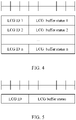
- FIG. 4 is a schematic structural diagram of another example of a report format according to an embodiment of the present invention.
- the report format shown in FIG. 4 is a first report format.
- the first report format includes at least two sets of report information, and each set of the report information includes an LCG identity and an LCG buffer status.
- the LCG identity may include 3 bits bit, and the LCG identity indicates that an LCG has to-be-transmitted data, or is an ID value corresponding to an LCG having a to-be-sent buffer status report.
- the LCG buffer status may include 5 bits bit, and is used to indicate a buffer size corresponding to the LCG.
- the number of data groups in the to-be-sent buffer status report in such report format varies with the actual number of LCGs with a to-be-sent buffer status report.
- the first report format and the truncated first report format may alternatively be represented by using the same LCID value, and identified based on the number of bits and the number of buffer statuses. For example, if the number of bits that are 1 is the same as the number of buffer statuses, it indicates the first report format; if the number of bits that are 1 is different from the number of buffer statuses, it indicates the truncated first report format.
- the second report format may include: one set of report information, where the set of the report information includes an LCG identity and an LCG buffer status, the LCG identity is used to indicate an LCG having to-be-transmitted data, and the LCG buffer status is used to indicate a buffer size corresponding to the LCG.
- the second report format can only have one set of report information, while the first report format can have two or more sets of report information. Because the first report format may have at least two sets of report information, a total report length of the first report format is not fixed, and a length indication field is required to indicate its total report length. Because the second report format has only one set of report information, a total report length of the second report format is fixed, and no length indication field is required to indicate its total report length.
- FIG. 5 is a schematic structural diagram of still another example of a report format according to an embodiment of the present invention.
- the report format shown in FIG. 5 is a second report format.
- the second report format includes one set of report information, and the set of the report information includes an LCG identity and an LCG buffer status.
- the LCG identity may include 3 bits bit, and the LCG identity indicates that an LCG has to-be-transmitted data, or is an ID value corresponding to an LCG having a to-be-sent buffer status report.
- the LCG buffer status may include 5 bits bit, and is used to indicate a buffer size corresponding to the LCG.
- the truncated second report format is used mainly because a resource space is insufficient to accommodate a complete target buffer status report.
- the target buffer status report is truncated, so as to fully utilize a small resource to report important buffer status information to the network device as soon as possible.
- the truncation method of the second report format is similar to the truncation method of the first report format, and is not repeated herein.
- the second report format and the truncated second report format are distinguished to further refine the report information, so that the network device can determine whether only one LCG has a buffer status or a buffer status of only one LCG can be reported due to limited resources.
- the first report format and the truncated first report format may also be represented by using the same LCID value.
- the network device may determine that only one LCG has a buffer status, and that the target buffer status report is in the second report format. If in an entire MAC protocol data unit (Protocol Data Unit, PDU), the target buffer status report is data with a lowest transmission priority, the target buffer status report may be in the truncated second report format.
- the specific method of S230 may include: in a case that there is an available uplink resource corresponding to the target buffer status report, sending the target buffer status report to the network device by using the available uplink resource.
- the available uplink resource may be a new uplink transmission resource and/or an uplink resource for use by a logical channel that is not restrained from triggering the target buffer status report.
- the available uplink resource may be a new uplink transmission resource for use by a logical channel that is not restrained from triggering the target buffer status report.
- the relay terminal device may directly send the target buffer status report to the network device on the available uplink resource.
- the specific method of S230 may further include:
- the available uplink resource may be a new uplink transmission resource and/or an uplink resource for use by a logical channel that is not restrained from triggering the target buffer status report.
- the available uplink resource may be a new uplink transmission resource for use by a logical channel that is not restrained from triggering the target buffer status report.
- the relay terminal device needs to send an SR to the network device first, so that the network device allocates an available uplink resource to the relay terminal device based on the SR; and the relay terminal device sends the target buffer status report to the network device on the available uplink resource allocated by the network device.
- the LCG when none of logical channels in one LCG of the relay terminal device has buffered data, if the LCG has a target buffer status report that needs to be reported, no regular BSR is triggered.
- the regular BSR is used to indicate that none of the logical channels in the LCG has buffered data.
- the relay terminal device needs to reuse and group various types of data at the MAC layer. Therefore, the various types of data need to be sorted by priority. In the case of insufficient resources, data with a higher priority will be transmitted first.
- the specific method of S230 may further include:
- a transmission priority of a normally reported target buffer status report is higher than the transmission priority of the target buffer status report used as padding information.
- the target buffer status report is represented as a pre-BSR, and transmission priorities sorted in descending order according to the preset transmission priorities are as follows:
- Options 1 to 3 represent possible locations of the transmission priorities of the to-be-sent buffer status reports other than the to-be-sent buffer status reports for padding, that is, possible locations of the transmission priorities of normally reported target buffer status reports.
- Alts 1 and 2 represent possible locations of the transmission priorities of the to-be-sent buffer status reports for padding, that is, possible locations of the transmission priorities of the target buffer status reports as padding information.
- the transmission priority of the target buffer status report in multiple pieces of to-be-transmitted data may be determined, and based on the determined transmission priority, the target buffer status report is reported to the network device according to the priority order.
- the buffer status reporting method may further include: receiving report configuration information sent by the network device, where the report configuration information may include an on-off configuration of the target buffer status report.
- the specific method of S220 may include: generating the target buffer status report based on the data information in the case that the on-off configuration is on.
- the relay terminal device even if the relay terminal device is capable of uploading the target buffer status report, the relay terminal device still needs to receive the on-off configuration of the target buffer status report sent by the network device.
- the relay terminal device In the case that the on-off configuration is on, the relay terminal device generates the target buffer status report based on the data information; in the case that the on-off configuration is off, the relay terminal device does not generate the target buffer status report based on data information.
- the report configuration information may further include a generation configuration of the target buffer status report.
- the specific method of S220 may include: generating the target buffer status report based on the data information and the generation configuration.
- the generation configuration of the target buffer status report may include at least one of the following:
- the relay terminal device may generate the corresponding target buffer status report based on the generation configuration configured by the network device for the relay terminal device.
- the report configuration information may further include a reporting configuration of the target buffer status report.
- the specific method of S230 may include: reporting the target buffer status report to the network device based on the reporting configuration.
- the reporting configuration of the target buffer status report may include at least one of the following:
- the relay terminal device may report the target buffer status report to the network device based on the reporting configuration configured by the network device for the relay terminal device.
- the buffer status reporting method may further include: reporting a report capability parameter to the network device, where the report capability parameter is used by the network device to configure the report configuration information for the relay terminal device.
- the relay terminal device needs to first report the report capability parameter to the network device, for example, whether reporting of the target buffer status report is supported, which generation method is supported, or which reporting method is supported, so that the network device configures the report configuration information for the relay terminal device based on the report capability parameter reported by the relay terminal device.
- the buffer status reporting method enables the relay terminal device to pre-report a buffer status of data information to-be-transmitted information to the network device after learning the data information of the to-be-transmitted data that the remote terminal device is about to transmit to the network device through the relay terminal device, thereby reducing a delay in reporting the buffer status of the to-be-transmitted data by the relay terminal device, increasing the timeliness of uplink scheduling, and improving system performance and user experience of a sidelink transmission system.
- FIG. 6 is a schematic structural diagram of an embodiment of a relay terminal device according to the present invention.
- the relay terminal device shown in FIG. 6 may be configured to forward to a network device data sent from a remote terminal device to the relay terminal device.
- the relay terminal device may be the relay UE 120 shown in FIG. 1
- the remote terminal device may be the remote UE 130 shown in FIG. 1
- the network device may be the base station 110 shown in FIG. 1 .
- the relay terminal device 300 may include:
- the relay terminal device 300 can generate a to-be-sent buffer status report based on the data information, and report the to-be-sent buffer status report to the network device, so as to request, before receiving the to-be-transmitted data, the network device to pre-allocate an uplink resource corresponding to the to-be-transmitted data to the relay terminal device 300 based on the to-be-sent buffer status report, so that the relay terminal device 300 can complete the reporting of the buffer status of the to-be-transmitted data before the remote terminal device buffers the to-be-transmitted data in the relay terminal device 300.
- the information determining module 310 may be specifically configured to:
- the reporting module 330 may be specifically configured to: in a case that there is an available uplink resource corresponding to the target buffer status report, send the target buffer status report to the network device by using the available uplink resource.
- the reporting module 330 may be further specifically configured to:
- the available uplink resource includes at least one of the following:
- the data information includes a data size of the to-be-transmitted data and service information corresponding to the to-be-transmitted data.
- the service information includes logical channel group LCG information of the to-be-transmitted data on a sidelink sidelink interface or a service priority corresponding to the to-be-transmitted data.
- the report generation module 320 may be specifically configured to:
- the preset mapping relationship is determined according to a network configuration or a preset rule.
- the preset rule includes a same-priority rule.
- the target buffer status report includes a media access control subheader MAC subheader, and the MAC subheader includes a logical channel identity LCID field, where
- the first report format includes at least one of the following:
- the second report format includes: one set of report information, where the set of the report information includes an LCG identity and an LCG buffer status, the LCG identity is used to indicate an LCG having to-be-transmitted data, and the LCG buffer status is used to indicate a buffer size corresponding to the LCG.
- the target buffer status report further includes a length indication field, where the length indication field is used to indicate the total report length.
- the reporting module 330 may be further specifically configured to:
- the relay terminal device 300 may further include: a configuration receiving module, configured to, before the data information of the to-be-transmitted data is determined, receive report configuration information sent by the network device, where the report configuration information may include an on-off configuration of the target buffer status report.
- the report generation module 320 may be specifically configured to: generate the target buffer status report based on the data information in the case that the on-off configuration is on.
- the report configuration information may further include a generation configuration of the target buffer status report.
- the report generation module 320 may be specifically configured to: generate the target buffer status report based on the data information and the generation configuration.
- the generation configuration of the target buffer status report may include at least one of the following:
- the report configuration information may further include a reporting configuration of the target buffer status report.
- the reporting module 330 may be specifically configured to: report the target buffer status report to the network device based on the reporting configuration.
- the reporting configuration of the target buffer status report may include at least one of the following:
- the relay terminal device 300 may further include: a parameter reporting module, configured to, before the report configuration information sent by the network device is received, report a report capability parameter to the network device, where the report capability parameter is used by the network device to configure the report configuration information for the relay terminal device 300.
- a parameter reporting module configured to, before the report configuration information sent by the network device is received, report a report capability parameter to the network device, where the report capability parameter is used by the network device to configure the report configuration information for the relay terminal device 300.
- the relay terminal device 300 provided in this embodiment of the present invention is capable of implementing various processes and effects implemented by the relay terminal device 300 in the method embodiments of FIG. 2 to FIG. 5 . To avoid repetition, details are not described herein again.
- FIG. 7 is a schematic diagram of a hardware structure of an embodiment of a relay terminal device according to the present invention.
- the relay terminal device 400 includes but is not limited to components, for example, a radio frequency unit 401, a network module 402, an audio output unit 403, an input unit 404, a sensor 405, a display unit 406, a user input unit 407, an interface unit 408, a memory 409, a processor 410, and a power supply 411.
- a radio frequency unit 401 for example, a radio frequency unit 401, a network module 402, an audio output unit 403, an input unit 404, a sensor 405, a display unit 406, a user input unit 407, an interface unit 408, a memory 409, a processor 410, and a power supply 411.
- the relay terminal device is not limited to the relay terminal device structure shown in FIG. 7 .
- the relay terminal device may include more or fewer components than those shown in the figure, or combine some of the components, or arrange the components differently.
- the processor 410 is configured to: determine data information of to-be-transmitted data, where the to-be-transmitted data is data which is about to be sent by a remote terminal device to a network device through the relay terminal device; generate a target buffer status report based on the data information, where the target buffer status report is a to-be-sent buffer status report; and report the target buffer status report to the network device.
- the relay terminal device can generate a to-be-sent buffer status report based on the data information, and report the to-be-sent buffer status report to the network device, so as to request, before receiving the to-be-transmitted data, the network device to pre-allocate an uplink resource corresponding to the to-be-transmitted data to the relay terminal device based on the to-be-sent buffer status report, so that the relay terminal device can complete the reporting of the buffer status of the to-be-transmitted data before the remote terminal device buffers the to-be-transmitted data in the relay terminal device.
- the radio frequency unit 401 may be configured to receive and send a signal during sending and receiving information or a call process. Specifically, the radio frequency unit 401 sends downlink information received from a base station to the processor 410 for processing, and in addition, sends uplink data to the base station.
- the radio frequency unit 401 includes but is not limited to an antenna, at least one amplifier, a transceiver, a coupler, a low noise amplifier, a duplexer, and the like.
- the radio frequency unit 401 may also communicate with a network and other devices via a wireless communications system.
- the relay terminal device provides the user with wireless broadband Internet access by using the network module 402, for example, helping the user send or receive an email, browse a web page, and access streaming media.
- the audio output unit 403 may convert audio data received by the radio frequency unit 401 or the network module 402 or stored in the memory 409 into an audio signal and output the audio signal as a sound.
- the audio output unit 403 may also provide audio output (for example, a call signal received sound or a message received sound) associated with a specific function performed by the relay terminal device 400.
- the audio output unit 403 includes a speaker, a buzzer, a receiver, and the like.
- the input unit 404 is configured to receive an audio or video signal.
- the input unit 404 may include a graphics processing unit (Graphics Processing Unit, GPU) 4041 and a microphone 4042, and the graphics processing unit 4041 processes image data of a static picture or a video obtained by an image capture apparatus (for example, a camera) in an image capture mode or a video capture mode.
- a processed image frame may be displayed on the display unit 406.
- the image frame processed by the graphics processing unit 4041 may be stored in the memory 409 (or another storage medium) or transmitted by using the radio frequency unit 401 or the network module 402.
- the microphone 4042 can receive sounds and process such sounds into audio data.
- the processed audio data can be converted in a telephone call mode into a format that can be transmitted by the radio frequency unit 401 to a mobile communication base station, for outputting.
- the relay terminal device 400 further includes at least one sensor 405, for example, an optical sensor, a motion sensor, and other sensors.
- the optical sensor includes an ambient light sensor and a proximity sensor.
- the ambient light sensor may adjust brightness of a display panel 4061 based on intensity of ambient light.
- the proximity sensor may disable the display panel 4061 and/or backlight.
- an accelerometer sensor may detect magnitudes of accelerations in various directions (typically three axes), and in a stationary state, may detect the magnitude and direction of gravity, and may be applied for posture recognition of the relay terminal device (for example, switching between a landscape orientation and a portrait orientation, related gaming, and magnetometer posture calibration), vibration recognition related functions (for example, pedometer and tapping), and the like.
- the sensor 405 may further include a fingerprint sensor, a pressure sensor, an iris sensor, a molecular sensor, a gyroscope, a barometer, a hygrometer, a thermometer, an infrared sensor, and the like. Details are not described herein.
- the display unit 406 is configured to display information input by the user or information provided to the user.
- the display unit 406 may include the display panel 4061.
- the display panel 4061 may be configured in a form of a liquid crystal display (Liquid Crystal Display, LCD), an organic light-emitting diode (Organic Light-Emitting Diode, OLED), or the like.
- the user input unit 407 may be configured to receive entered numerical or character information, and generate key signal input that is related to user setting and function control of the relay terminal device.
- the user input unit 407 includes a touch panel 4071 and other input devices 4072.
- the touch panel 4071 or referred to as a touchscreen, may capture a touch operation performed by a user on or near the touch panel 4071 (for example, an operation performed by the user on the touch panel 4071 or near the touch panel 4071 by using any appropriate object or accessory such as a finger or a stylus).
- the touch panel 4071 may include two parts: a touch detection apparatus and a touch controller.
- the touch detection apparatus detects a touch direction of a user, detects a signal brought by a touch operation, and transmits the signal to the touch controller.
- the touch controller receives touch information from the touch detection apparatus, converts the touch information into touchpoint coordinates, transmits the touchpoint coordinates to the processor 410, and receives and executes a command transmitted by the processor 410.
- the touch panel 4071 may be implemented in multiple forms, for example, as a resistive, capacitive, infrared, or surface acoustic wave touch panel.
- the user input unit 407 may further include other input devices 4072.
- the other input devices 4072 may include but are not limited to a physical keyboard, a function key (for example, a volume control key or a power on/off key), a trackball, a mouse, and a joystick. Details are not described herein.
- the touch panel 4071 may cover the display panel 4061. After detecting a touch operation on or near the touch panel 4071, the touch panel 4071 transmits the touch operation to the processor 410 to determine a type of a touch event. Then the processor 410 provides corresponding visual output on the display panel 4061 based on the type of the touch event.
- the touch panel 4071 and the display panel 4061 are used as two separate components to implement input and output functions of the relay terminal device in FIG. 7 , the touch panel 4071 and the display panel 4061 may be integrated to implement the input and output functions of the relay terminal device in some embodiments. This is not specifically limited herein.
- the interface unit 408 is an interface for connecting an external apparatus to the relay terminal device 400.
- the external apparatus may include a wired or wireless headphone port, an external power (or battery charger) port, a wired or wireless data port, a memory card port, a port for connecting an apparatus provided with a recognition module, an audio input/output (I/O) port, a video I/O port, an earphone port, and the like.
- the interface unit 408 may be configured to receive an input (for example, data information or power) from an external apparatus and transmit the received input to one or more elements within the relay terminal device 400, or may be configured to transmit data between the relay terminal device 400 and the external apparatus.
- the memory 409 may be configured to store software programs and various data.
- the memory 409 may mainly include a program storage area and a data storage area.
- the program storage area may store an operating system, an application program required for at least one function (for example, a sound play function and an image play function), and the like.
- the data storage area may store data created based on use of the mobile phone (for example, audio data and a phone book), and the like.
- the memory 409 may include a high-speed random access memory, or may further include a non-volatile memory, for example, at least one magnetic disk storage device, a flash memory, or another volatile solid-state storage device.
- the processor 410 is a control center of the relay terminal device.
- the processor 410 uses various interfaces and lines to connect all parts of the entire relay terminal device, and performs various functions and data processing of the relay terminal device by running or executing the software program and/or module stored in the memory 409 and invoking data stored in the memory 409, thereby performing overall monitoring on the relay terminal device.
- the processor 410 may include one or more processing units.
- the processor 410 may integrate an application processor and a modem processor.
- the application processor mainly processes the operating system, a user interface, an application program, and the like.
- the modem processor mainly processes wireless communication. It can be understood that the modem processor may alternatively be not integrated in the processor 410.
- the relay terminal device 400 may further include the power supply 411 (for example, a battery) for powering the various components.
- the power supply 411 may be logically connected to the processor 410 through a power management system, so that functions such as charge and discharge management and power consumption management are implemented by using the power management system.
- the relay terminal device 400 includes some functional modules that are not shown. Details are not described herein.
- an embodiment of the present invention further provides a relay terminal device, including a processor 410, a memory 409, and a computer program stored in the memory 409 and capable of running on the processor 410.
- a relay terminal device including a processor 410, a memory 409, and a computer program stored in the memory 409 and capable of running on the processor 410.
- the computer program is executed by the processor 410, the processes of the foregoing buffer status reporting method embodiment are implemented, with the same technical effects achieved. To avoid repetition, details are not described herein again.
- An embodiment of the present invention further provides a computer-readable storage medium, where the computer-readable storage medium stores a computer program.
- the computer program When the computer program is executed by a processor, the processes of the foregoing buffer status reporting method embodiment are implemented, with the same technical effects achieved. To avoid repetition, details are not described herein again.
- the computer-readable storage medium may include a non-transitory computer-readable storage medium such as a read-only memory (Read-Only Memory, ROM), a random access memory (Random Access Memory, RAM), a magnetic disk, or an optical disc.
- the method in the foregoing embodiments may be implemented by software in addition to a necessary universal hardware platform or by hardware only. In most cases, the former is a preferred implementation.
- the technical solutions of the present invention essentially, or the part contributing to the prior art may be implemented in a form of a software product.
- the software product is stored in a storage medium (for example, ROM/RAM, a magnetic disk, or an optical disc), and includes several instructions for instructing a terminal (which may be a mobile phone, a computer, a server, an air conditioner, a network device, or the like) to perform the method described in the embodiments of the present invention.
- Such processor may be, but is not limited to, a general-purpose processor, a dedicated processor, a special application processor, or a field programmable logic circuit. It should be also understood that each block in the block diagrams and/or the flowcharts and a combination of the blocks in the block diagrams and/or the flowcharts may be implemented by a dedicated hardware for executing a specified function or action or may be implemented by a combination of dedicated hardware and computer instructions.
Landscapes
- Engineering & Computer Science (AREA)
- Computer Networks & Wireless Communication (AREA)
- Signal Processing (AREA)
- Mobile Radio Communication Systems (AREA)
- Information Transfer Between Computers (AREA)
- Data Exchanges In Wide-Area Networks (AREA)
Applications Claiming Priority (2)
| Application Number | Priority Date | Filing Date | Title |
|---|---|---|---|
| CN202010113966.1A CN113301604B (zh) | 2020-02-24 | 2020-02-24 | 缓存状态上报方法、中继终端设备及计算机可读存储介质 |
| PCT/CN2021/077540 WO2021169965A1 (zh) | 2020-02-24 | 2021-02-24 | 缓存状态上报方法、中继终端设备及计算机可读存储介质 |
Publications (3)
| Publication Number | Publication Date |
|---|---|
| EP4099754A1 true EP4099754A1 (de) | 2022-12-07 |
| EP4099754A4 EP4099754A4 (de) | 2023-06-14 |
| EP4099754B1 EP4099754B1 (de) | 2025-11-05 |
Family
ID=77317894
Family Applications (1)
| Application Number | Title | Priority Date | Filing Date |
|---|---|---|---|
| EP21760204.4A Active EP4099754B1 (de) | 2020-02-24 | 2021-02-24 | Cache-zustandsmeldeverfahren, relaisendgerät und computerlesbares speichermedium |
Country Status (8)
| Country | Link |
|---|---|
| US (1) | US12328729B2 (de) |
| EP (1) | EP4099754B1 (de) |
| JP (1) | JP7516534B2 (de) |
| KR (1) | KR102845555B1 (de) |
| CN (1) | CN113301604B (de) |
| ES (1) | ES3054038T3 (de) |
| PH (1) | PH12022552180A1 (de) |
| WO (1) | WO2021169965A1 (de) |
Families Citing this family (8)
| Publication number | Priority date | Publication date | Assignee | Title |
|---|---|---|---|---|
| CN113923711B (zh) * | 2020-07-09 | 2024-10-18 | 大唐移动通信设备有限公司 | 缓冲区状态报告的上报方法、装置及中继终端 |
| CN114567905B (zh) * | 2020-11-27 | 2025-02-28 | 展讯半导体(南京)有限公司 | 触发边链路中继系统缓存状态报告方法及用户设备、介质 |
| EP4402936A4 (de) * | 2021-09-15 | 2024-10-30 | NEC Corporation | Verfahren, vorrichtungen und computerlesbares medium zur kommunikation |
| CN116113017B (zh) * | 2021-11-10 | 2026-03-27 | 北京小米移动软件有限公司 | 资源调度方法及装置、存储介质 |
| CN116170818A (zh) * | 2021-11-24 | 2023-05-26 | 维沃移动通信有限公司 | 信息上报方法、配置方法、装置、终端及网络侧设备 |
| EP4221399A1 (de) * | 2022-01-28 | 2023-08-02 | Nokia Technologies Oy | Vorrichtung und verfahren zur weiterleitung von daten von einer entfernten vorrichtung zu einem netzknoten |
| CN114867063B (zh) * | 2022-04-12 | 2025-11-18 | 北京小米移动软件有限公司 | 上行数据传输方法、装置、终端设备和存储介质 |
| CN118283696A (zh) * | 2022-12-29 | 2024-07-02 | 华为技术有限公司 | 通信方法、通信装置及通信系统 |
Family Cites Families (16)
| Publication number | Priority date | Publication date | Assignee | Title |
|---|---|---|---|---|
| US7961683B2 (en) * | 2004-09-30 | 2011-06-14 | Alcatel-Lucent Usa Inc. | Active session mobility solution for point-to-point protocol |
| US8248941B2 (en) | 2008-02-01 | 2012-08-21 | Nokia Siemens Networks Oy | Method, apparatus and computer program for uplink scheduling in a network that employs relay nodes |
| US8543054B2 (en) * | 2010-05-03 | 2013-09-24 | Telefonaktiebolaget L M Ericsson (Publ) | Method and apparatus for uplink scheduling using relays |
| CN102045851B (zh) * | 2011-01-25 | 2013-09-04 | 华中科技大学 | 一种中继网络中的上行资源分配方法和装置 |
| CN106535246B (zh) * | 2015-09-11 | 2021-03-16 | 中兴通讯股份有限公司 | 一种缓冲区状态报告的上报方法、装置及系统 |
| EP3148284B1 (de) * | 2015-09-25 | 2020-10-21 | ASUSTek Computer Inc. | Verfahren und vorrichtung zur lösung einer fehlanpassung zwischen einem sidelink-pufferstatusbericht und einer verfügbaren sidelink-übertragung in einem drahtloskommunikationssystem |
| CN108370561B (zh) * | 2015-12-30 | 2021-02-12 | 华为技术有限公司 | 一种链路资源的请求方法、用户设备及基站 |
| EP3255950A1 (de) * | 2016-06-06 | 2017-12-13 | ASUSTek Computer Inc. | Verfahren und vorrichtung zur ressourcenzuweisung für ein d2d relais in einem drahtloskommunikationssystem |
| US10869329B2 (en) * | 2016-09-30 | 2020-12-15 | Huawei Technologies Co., Ltd. | Resource request method and system, and device |
| CN109392008B (zh) * | 2017-08-11 | 2021-01-29 | 华为技术有限公司 | 通信方法与设备 |
| CN109587726B (zh) * | 2017-09-28 | 2021-08-13 | 华为技术有限公司 | 通信方法、终端设备和接入网设备 |
| CN110113781B (zh) * | 2018-02-01 | 2022-05-31 | 大唐移动通信设备有限公司 | 缓冲区状态报告的上报、资源分配方法、终端及网络设备 |
| CN111148147B (zh) * | 2018-11-02 | 2023-10-03 | 维沃移动通信有限公司 | 一种bsr上报方法和中继节点 |
| CN111586751B (zh) * | 2019-02-15 | 2023-09-26 | 华为技术有限公司 | 一种缓存状态报告bsr的触发方法、通信装置 |
| US11595818B2 (en) * | 2019-06-24 | 2023-02-28 | Forescout Technologies, Inc. | Adaptive scanning |
| US12245071B2 (en) * | 2020-02-13 | 2025-03-04 | Qualcomm Incorporated | Continuity for buffer status reports |
-
2020
- 2020-02-24 CN CN202010113966.1A patent/CN113301604B/zh active Active
-
2021
- 2021-02-24 WO PCT/CN2021/077540 patent/WO2021169965A1/zh not_active Ceased
- 2021-02-24 EP EP21760204.4A patent/EP4099754B1/de active Active
- 2021-02-24 ES ES21760204T patent/ES3054038T3/es active Active
- 2021-02-24 JP JP2022550819A patent/JP7516534B2/ja active Active
- 2021-02-24 KR KR1020227029833A patent/KR102845555B1/ko active Active
- 2021-02-24 PH PH1/2022/552180A patent/PH12022552180A1/en unknown
-
2022
- 2022-08-23 US US17/893,259 patent/US12328729B2/en active Active
Also Published As
| Publication number | Publication date |
|---|---|
| US12328729B2 (en) | 2025-06-10 |
| EP4099754B1 (de) | 2025-11-05 |
| ES3054038T3 (en) | 2026-01-28 |
| JP7516534B2 (ja) | 2024-07-16 |
| PH12022552180A1 (en) | 2023-12-11 |
| CN113301604B (zh) | 2023-04-07 |
| KR102845555B1 (ko) | 2025-08-11 |
| WO2021169965A1 (zh) | 2021-09-02 |
| US20220408466A1 (en) | 2022-12-22 |
| EP4099754A4 (de) | 2023-06-14 |
| CN113301604A (zh) | 2021-08-24 |
| JP2023514854A (ja) | 2023-04-11 |
| KR20220133974A (ko) | 2022-10-05 |
Similar Documents
| Publication | Publication Date | Title |
|---|---|---|
| US12328729B2 (en) | Buffer status reporting method, relay terminal device, and computer-readable storage medium | |
| US11800400B2 (en) | Transmission collision processing method, terminal, and control node | |
| US12058684B2 (en) | Resource configuration method, resource determining method, network side device and terminal | |
| CN110035503B (zh) | 资源状态的配置方法、激活或去激活方法、基站及终端 | |
| CN111435905A (zh) | 一种信息发送方法及终端 | |
| JP7317949B2 (ja) | 伝送方法および関連装置 | |
| EP3860226A1 (de) | Zugriffssteuerungsverfahren, endgerät und netzwerkseitige vorrichtung | |
| KR20210116593A (ko) | 정보 보고 방법, 자원 할당 방법, 제1 단말 및 제2 단말 | |
| WO2021027713A1 (zh) | 上行传输方法、上行传输控制方法及相关设备 | |
| US12418891B2 (en) | Feedback information transmission method and apparatus, device, and medium | |
| CN110958710A (zh) | 信道接入方法、配置方法、终端及网络侧设备 | |
| US12309834B2 (en) | Listen-before-talk failure processing method, terminal, and network side device | |
| CN110198560B (zh) | 一种功率配置方法和终端 | |
| US12574774B2 (en) | Transmission processing method and terminal | |
| CN111835481B (zh) | 上行传输方法、终端和网络侧设备 | |
| CN110022578B (zh) | 一种bsr上报方法和移动终端 | |
| CN111601383A (zh) | 一种资源分配方法、终端和网络设备 | |
| CN112788769B (zh) | 一种信息处理方法、设备及系统 | |
| CN110035553A (zh) | 资源调度请求方法、装置和移动终端 | |
| HK40067337A (en) | Feedback information transmission method and apparatus, device, and medium |
Legal Events
| Date | Code | Title | Description |
|---|---|---|---|
| STAA | Information on the status of an ep patent application or granted ep patent |
Free format text: STATUS: THE INTERNATIONAL PUBLICATION HAS BEEN MADE |
|
| PUAI | Public reference made under article 153(3) epc to a published international application that has entered the european phase |
Free format text: ORIGINAL CODE: 0009012 |
|
| STAA | Information on the status of an ep patent application or granted ep patent |
Free format text: STATUS: REQUEST FOR EXAMINATION WAS MADE |
|
| 17P | Request for examination filed |
Effective date: 20220901 |
|
| AK | Designated contracting states |
Kind code of ref document: A1 Designated state(s): AL AT BE BG CH CY CZ DE DK EE ES FI FR GB GR HR HU IE IS IT LI LT LU LV MC MK MT NL NO PL PT RO RS SE SI SK SM TR |
|
| DAV | Request for validation of the european patent (deleted) | ||
| DAX | Request for extension of the european patent (deleted) | ||
| A4 | Supplementary search report drawn up and despatched |
Effective date: 20230517 |
|
| RIC1 | Information provided on ipc code assigned before grant |
Ipc: H04W 28/02 20090101AFI20230511BHEP |
|
| GRAP | Despatch of communication of intention to grant a patent |
Free format text: ORIGINAL CODE: EPIDOSNIGR1 |
|
| STAA | Information on the status of an ep patent application or granted ep patent |
Free format text: STATUS: GRANT OF PATENT IS INTENDED |
|
| INTG | Intention to grant announced |
Effective date: 20250623 |
|
| GRAS | Grant fee paid |
Free format text: ORIGINAL CODE: EPIDOSNIGR3 |
|
| GRAA | (expected) grant |
Free format text: ORIGINAL CODE: 0009210 |
|
| STAA | Information on the status of an ep patent application or granted ep patent |
Free format text: STATUS: THE PATENT HAS BEEN GRANTED |
|
| AK | Designated contracting states |
Kind code of ref document: B1 Designated state(s): AL AT BE BG CH CY CZ DE DK EE ES FI FR GB GR HR HU IE IS IT LI LT LU LV MC MK MT NL NO PL PT RO RS SE SI SK SM TR |
|
| REG | Reference to a national code |
Ref country code: CH Ref legal event code: F10 Free format text: ST27 STATUS EVENT CODE: U-0-0-F10-F00 (AS PROVIDED BY THE NATIONAL OFFICE) Effective date: 20251105 Ref country code: GB Ref legal event code: FG4D |
|
| REG | Reference to a national code |
Ref country code: DE Ref legal event code: R096 Ref document number: 602021041810 Country of ref document: DE |
|
| REG | Reference to a national code |
Ref country code: IE Ref legal event code: FG4D |
|
| REG | Reference to a national code |
Ref country code: NL Ref legal event code: FP |
|
| PGFP | Annual fee paid to national office [announced via postgrant information from national office to epo] |
Ref country code: FR Payment date: 20251231 Year of fee payment: 6 |
|
| REG | Reference to a national code |
Ref country code: ES Ref legal event code: FG2A Ref document number: 3054038 Country of ref document: ES Kind code of ref document: T3 Effective date: 20260128 |
|
| PGFP | Annual fee paid to national office [announced via postgrant information from national office to epo] |
Ref country code: NL Payment date: 20260106 Year of fee payment: 6 |
|
| PGFP | Annual fee paid to national office [announced via postgrant information from national office to epo] |
Ref country code: GB Payment date: 20260106 Year of fee payment: 6 |
|
| PGFP | Annual fee paid to national office [announced via postgrant information from national office to epo] |
Ref country code: ES Payment date: 20260311 Year of fee payment: 6 |
|
| REG | Reference to a national code |
Ref country code: LT Ref legal event code: MG9D |
|
| PG25 | Lapsed in a contracting state [announced via postgrant information from national office to epo] |
Ref country code: NO Free format text: LAPSE BECAUSE OF FAILURE TO SUBMIT A TRANSLATION OF THE DESCRIPTION OR TO PAY THE FEE WITHIN THE PRESCRIBED TIME-LIMIT Effective date: 20260205 |
|
| PGFP | Annual fee paid to national office [announced via postgrant information from national office to epo] |
Ref country code: DE Payment date: 20260102 Year of fee payment: 6 |
|
| PG25 | Lapsed in a contracting state [announced via postgrant information from national office to epo] |
Ref country code: AT Free format text: LAPSE BECAUSE OF FAILURE TO SUBMIT A TRANSLATION OF THE DESCRIPTION OR TO PAY THE FEE WITHIN THE PRESCRIBED TIME-LIMIT Effective date: 20251105 Ref country code: FI Free format text: LAPSE BECAUSE OF FAILURE TO SUBMIT A TRANSLATION OF THE DESCRIPTION OR TO PAY THE FEE WITHIN THE PRESCRIBED TIME-LIMIT Effective date: 20251105 Ref country code: HR Free format text: LAPSE BECAUSE OF FAILURE TO SUBMIT A TRANSLATION OF THE DESCRIPTION OR TO PAY THE FEE WITHIN THE PRESCRIBED TIME-LIMIT Effective date: 20251105 |
|
| REG | Reference to a national code |
Ref country code: AT Ref legal event code: MK05 Ref document number: 1855772 Country of ref document: AT Kind code of ref document: T Effective date: 20251105 |
|
| PG25 | Lapsed in a contracting state [announced via postgrant information from national office to epo] |
Ref country code: RS Free format text: LAPSE BECAUSE OF FAILURE TO SUBMIT A TRANSLATION OF THE DESCRIPTION OR TO PAY THE FEE WITHIN THE PRESCRIBED TIME-LIMIT Effective date: 20260205 |
|
| PG25 | Lapsed in a contracting state [announced via postgrant information from national office to epo] |
Ref country code: IS Free format text: LAPSE BECAUSE OF FAILURE TO SUBMIT A TRANSLATION OF THE DESCRIPTION OR TO PAY THE FEE WITHIN THE PRESCRIBED TIME-LIMIT Effective date: 20260305 |
|
| PG25 | Lapsed in a contracting state [announced via postgrant information from national office to epo] |
Ref country code: PT Free format text: LAPSE BECAUSE OF FAILURE TO SUBMIT A TRANSLATION OF THE DESCRIPTION OR TO PAY THE FEE WITHIN THE PRESCRIBED TIME-LIMIT Effective date: 20260305 |
|
| PG25 | Lapsed in a contracting state [announced via postgrant information from national office to epo] |
Ref country code: PL Free format text: LAPSE BECAUSE OF FAILURE TO SUBMIT A TRANSLATION OF THE DESCRIPTION OR TO PAY THE FEE WITHIN THE PRESCRIBED TIME-LIMIT Effective date: 20251105 |
|
| PG25 | Lapsed in a contracting state [announced via postgrant information from national office to epo] |
Ref country code: LV Free format text: LAPSE BECAUSE OF FAILURE TO SUBMIT A TRANSLATION OF THE DESCRIPTION OR TO PAY THE FEE WITHIN THE PRESCRIBED TIME-LIMIT Effective date: 20251105 |