EP4099705A1 - Communication terminal, image communication system, method for displaying image, and carrier means - Google Patents
Communication terminal, image communication system, method for displaying image, and carrier means Download PDFInfo
- Publication number
- EP4099705A1 EP4099705A1 EP22176038.2A EP22176038A EP4099705A1 EP 4099705 A1 EP4099705 A1 EP 4099705A1 EP 22176038 A EP22176038 A EP 22176038A EP 4099705 A1 EP4099705 A1 EP 4099705A1
- Authority
- EP
- European Patent Office
- Prior art keywords
- image
- predetermined
- area
- communication terminal
- communication
- Prior art date
- Legal status (The legal status is an assumption and is not a legal conclusion. Google has not performed a legal analysis and makes no representation as to the accuracy of the status listed.)
- Pending
Links
- 238000004891 communication Methods 0.000 title claims abstract description 438
- 238000000034 method Methods 0.000 title claims description 54
- 238000003860 storage Methods 0.000 claims abstract description 35
- 238000007726 management method Methods 0.000 description 158
- 238000003384 imaging method Methods 0.000 description 59
- 238000009826 distribution Methods 0.000 description 53
- 230000005540 biological transmission Effects 0.000 description 38
- 230000008569 process Effects 0.000 description 38
- 230000001360 synchronised effect Effects 0.000 description 28
- 238000010586 diagram Methods 0.000 description 24
- 230000008859 change Effects 0.000 description 19
- 230000006870 function Effects 0.000 description 16
- 238000013523 data management Methods 0.000 description 13
- 230000004044 response Effects 0.000 description 10
- 230000001133 acceleration Effects 0.000 description 7
- 239000013256 coordination polymer Substances 0.000 description 7
- 239000007787 solid Substances 0.000 description 6
- 238000006243 chemical reaction Methods 0.000 description 5
- 238000010801 machine learning Methods 0.000 description 5
- 238000005516 engineering process Methods 0.000 description 4
- 230000003287 optical effect Effects 0.000 description 3
- 238000003702 image correction Methods 0.000 description 2
- 230000005236 sound signal Effects 0.000 description 2
- 230000001052 transient effect Effects 0.000 description 2
- 230000000295 complement effect Effects 0.000 description 1
- 238000010276 construction Methods 0.000 description 1
- 239000012050 conventional carrier Substances 0.000 description 1
- 238000013135 deep learning Methods 0.000 description 1
- 230000000694 effects Effects 0.000 description 1
- 230000005484 gravity Effects 0.000 description 1
- 230000002452 interceptive effect Effects 0.000 description 1
- 230000007774 longterm Effects 0.000 description 1
- 230000005389 magnetism Effects 0.000 description 1
- 238000004519 manufacturing process Methods 0.000 description 1
- 239000000463 material Substances 0.000 description 1
- 229910044991 metal oxide Inorganic materials 0.000 description 1
- 150000004706 metal oxides Chemical class 0.000 description 1
- 239000000203 mixture Substances 0.000 description 1
- 238000010295 mobile communication Methods 0.000 description 1
- 238000003825 pressing Methods 0.000 description 1
- 230000002787 reinforcement Effects 0.000 description 1
- 239000004065 semiconductor Substances 0.000 description 1
- 230000003068 static effect Effects 0.000 description 1
Images


Classifications
-
- H—ELECTRICITY
- H04—ELECTRIC COMMUNICATION TECHNIQUE
- H04N—PICTORIAL COMMUNICATION, e.g. TELEVISION
- H04N21/00—Selective content distribution, e.g. interactive television or video on demand [VOD]
- H04N21/20—Servers specifically adapted for the distribution of content, e.g. VOD servers; Operations thereof
- H04N21/21—Server components or server architectures
- H04N21/218—Source of audio or video content, e.g. local disk arrays
- H04N21/21805—Source of audio or video content, e.g. local disk arrays enabling multiple viewpoints, e.g. using a plurality of cameras
-
- H—ELECTRICITY
- H04—ELECTRIC COMMUNICATION TECHNIQUE
- H04N—PICTORIAL COMMUNICATION, e.g. TELEVISION
- H04N23/00—Cameras or camera modules comprising electronic image sensors; Control thereof
- H04N23/60—Control of cameras or camera modules
- H04N23/698—Control of cameras or camera modules for achieving an enlarged field of view, e.g. panoramic image capture
-
- H—ELECTRICITY
- H04—ELECTRIC COMMUNICATION TECHNIQUE
- H04N—PICTORIAL COMMUNICATION, e.g. TELEVISION
- H04N21/00—Selective content distribution, e.g. interactive television or video on demand [VOD]
- H04N21/20—Servers specifically adapted for the distribution of content, e.g. VOD servers; Operations thereof
- H04N21/21—Server components or server architectures
- H04N21/218—Source of audio or video content, e.g. local disk arrays
- H04N21/2187—Live feed
-
- H—ELECTRICITY
- H04—ELECTRIC COMMUNICATION TECHNIQUE
- H04N—PICTORIAL COMMUNICATION, e.g. TELEVISION
- H04N21/00—Selective content distribution, e.g. interactive television or video on demand [VOD]
- H04N21/20—Servers specifically adapted for the distribution of content, e.g. VOD servers; Operations thereof
- H04N21/27—Server based end-user applications
- H04N21/274—Storing end-user multimedia data in response to end-user request, e.g. network recorder
- H04N21/2743—Video hosting of uploaded data from client
-
- H—ELECTRICITY
- H04—ELECTRIC COMMUNICATION TECHNIQUE
- H04N—PICTORIAL COMMUNICATION, e.g. TELEVISION
- H04N21/00—Selective content distribution, e.g. interactive television or video on demand [VOD]
- H04N21/40—Client devices specifically adapted for the reception of or interaction with content, e.g. set-top-box [STB]; Operations thereof
- H04N21/41—Structure of client; Structure of client peripherals
- H04N21/422—Input-only peripherals, i.e. input devices connected to specially adapted client devices, e.g. global positioning system [GPS]
- H04N21/4223—Cameras
-
- H—ELECTRICITY
- H04—ELECTRIC COMMUNICATION TECHNIQUE
- H04N—PICTORIAL COMMUNICATION, e.g. TELEVISION
- H04N21/00—Selective content distribution, e.g. interactive television or video on demand [VOD]
- H04N21/40—Client devices specifically adapted for the reception of or interaction with content, e.g. set-top-box [STB]; Operations thereof
- H04N21/47—End-user applications
- H04N21/472—End-user interface for requesting content, additional data or services; End-user interface for interacting with content, e.g. for content reservation or setting reminders, for requesting event notification, for manipulating displayed content
- H04N21/47217—End-user interface for requesting content, additional data or services; End-user interface for interacting with content, e.g. for content reservation or setting reminders, for requesting event notification, for manipulating displayed content for controlling playback functions for recorded or on-demand content, e.g. using progress bars, mode or play-point indicators or bookmarks
-
- H—ELECTRICITY
- H04—ELECTRIC COMMUNICATION TECHNIQUE
- H04N—PICTORIAL COMMUNICATION, e.g. TELEVISION
- H04N21/00—Selective content distribution, e.g. interactive television or video on demand [VOD]
- H04N21/40—Client devices specifically adapted for the reception of or interaction with content, e.g. set-top-box [STB]; Operations thereof
- H04N21/47—End-user applications
- H04N21/472—End-user interface for requesting content, additional data or services; End-user interface for interacting with content, e.g. for content reservation or setting reminders, for requesting event notification, for manipulating displayed content
- H04N21/4728—End-user interface for requesting content, additional data or services; End-user interface for interacting with content, e.g. for content reservation or setting reminders, for requesting event notification, for manipulating displayed content for selecting a Region Of Interest [ROI], e.g. for requesting a higher resolution version of a selected region
-
- H—ELECTRICITY
- H04—ELECTRIC COMMUNICATION TECHNIQUE
- H04N—PICTORIAL COMMUNICATION, e.g. TELEVISION
- H04N21/00—Selective content distribution, e.g. interactive television or video on demand [VOD]
- H04N21/40—Client devices specifically adapted for the reception of or interaction with content, e.g. set-top-box [STB]; Operations thereof
- H04N21/47—End-user applications
- H04N21/478—Supplemental services, e.g. displaying phone caller identification, shopping application
- H04N21/4788—Supplemental services, e.g. displaying phone caller identification, shopping application communicating with other users, e.g. chatting
-
- H—ELECTRICITY
- H04—ELECTRIC COMMUNICATION TECHNIQUE
- H04N—PICTORIAL COMMUNICATION, e.g. TELEVISION
- H04N21/00—Selective content distribution, e.g. interactive television or video on demand [VOD]
- H04N21/60—Network structure or processes for video distribution between server and client or between remote clients; Control signalling between clients, server and network components; Transmission of management data between server and client, e.g. sending from server to client commands for recording incoming content stream; Communication details between server and client
- H04N21/63—Control signaling related to video distribution between client, server and network components; Network processes for video distribution between server and clients or between remote clients, e.g. transmitting basic layer and enhancement layers over different transmission paths, setting up a peer-to-peer communication via Internet between remote STB's; Communication protocols; Addressing
- H04N21/643—Communication protocols
- H04N21/64322—IP
-
- H—ELECTRICITY
- H04—ELECTRIC COMMUNICATION TECHNIQUE
- H04N—PICTORIAL COMMUNICATION, e.g. TELEVISION
- H04N21/00—Selective content distribution, e.g. interactive television or video on demand [VOD]
- H04N21/60—Network structure or processes for video distribution between server and client or between remote clients; Control signalling between clients, server and network components; Transmission of management data between server and client, e.g. sending from server to client commands for recording incoming content stream; Communication details between server and client
- H04N21/65—Transmission of management data between client and server
- H04N21/658—Transmission by the client directed to the server
- H04N21/6587—Control parameters, e.g. trick play commands, viewpoint selection
-
- H—ELECTRICITY
- H04—ELECTRIC COMMUNICATION TECHNIQUE
- H04N—PICTORIAL COMMUNICATION, e.g. TELEVISION
- H04N21/00—Selective content distribution, e.g. interactive television or video on demand [VOD]
- H04N21/80—Generation or processing of content or additional data by content creator independently of the distribution process; Content per se
- H04N21/81—Monomedia components thereof
- H04N21/816—Monomedia components thereof involving special video data, e.g 3D video
-
- H—ELECTRICITY
- H04—ELECTRIC COMMUNICATION TECHNIQUE
- H04N—PICTORIAL COMMUNICATION, e.g. TELEVISION
- H04N23/00—Cameras or camera modules comprising electronic image sensors; Control thereof
- H04N23/60—Control of cameras or camera modules
- H04N23/66—Remote control of cameras or camera parts, e.g. by remote control devices
- H04N23/661—Transmitting camera control signals through networks, e.g. control via the Internet
-
- H—ELECTRICITY
- H04—ELECTRIC COMMUNICATION TECHNIQUE
- H04N—PICTORIAL COMMUNICATION, e.g. TELEVISION
- H04N7/00—Television systems
- H04N7/14—Systems for two-way working
- H04N7/141—Systems for two-way working between two video terminals, e.g. videophone
- H04N7/147—Communication arrangements, e.g. identifying the communication as a video-communication, intermediate storage of the signals
-
- H—ELECTRICITY
- H04—ELECTRIC COMMUNICATION TECHNIQUE
- H04N—PICTORIAL COMMUNICATION, e.g. TELEVISION
- H04N7/00—Television systems
- H04N7/14—Systems for two-way working
- H04N7/15—Conference systems
Definitions
- a communication terminal includes a transmitting and receiving unit configured to receive video data including a captured image, from a communication management system that manages the captured image distributed from another communication terminal different from the communication terminal; a determination unit configured to determine whether any predetermined-area information indicating a predetermined area of the captured image to be displayed during a reproduction time of the video data is stored in a storage unit; and a display control unit configured to control a display to display an image representing the predetermined area indicated by the predetermined-area information, based on a determination that the predetermined-area information is stored in the storage unit.
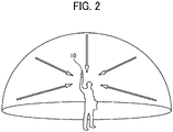
- the site where an image is captured is not limited to the office floor and may be any space that a user (or viewer) at a viewing site desires to remotely grasp, and examples of such a site include a school, a factory, a warehouse, a construction site, a server room, and a store.
- the image communication system 1 includes image capturing devices 10 (image capturing devices 10A and 10B) located at a plurality of sites (sites A and B), a communication management system 50, and communication terminals 30 (communication terminals 30A, 30C, and 30D) located at a plurality of sites (sites A, C, and D).
- the image capturing devices 10A and 10B are hereinafter referred to collectively as “image capturing devices 10" or individually as an “image capturing device 10" unless distinguished.
- the communication terminals 30A, 30C, and 30D are hereinafter referred to collectively as “communication terminals 30" or individually as a “communication terminal 30" unless distinguished.
- the communication terminal 30 and the communication management system 50 of the image communication system 1 are capable of communicating with each other via a communication network 100.
- the communication network 100 includes the Internet, a mobile communication network, and a local area network (LAN), for example.
- the communication network 100 includes a network by not only wired communications but also a network by wireless communications such as 3rd generation (3G), 4th generation (4G), 5th generation (5G), Wireless Fidelity (Wi-Fi) (registered trademark), Worldwide Interoperability for Microwave Access (WiMAX), or Long Term Evolution (LTE).
- 3G 3rd generation
- 4G 4th generation
- 5G 5th generation
- Wi-Fi Wireless Fidelity
- WiMAX Worldwide Interoperability for Microwave Access
- LTE Long Term Evolution
- An existing system for distributing video data including a spherical image allows a viewer to change a display direction for the video data as desired.
- Such an existing system allows a viewer at each site to view an image corresponding to a different display direction, regardless of whether the video data is distributed live in real time or is recorded and distributed.
- a distributor may desire viewers to view an image corresponding to a synchronized display direction in a time period during which an object that the distributor desires the viewers to view appears on the image or in a time period during which an object that the distributor does not desire the viewers to view appears on the image.
- the communication management system 50 stores predetermined-area information corresponding to a reproduction time of video data including a spherical image transmitted from the communication terminal 30, and transmits, to the communication terminal 30, the video data and the predetermined-area information corresponding to the reproduction time when recording and distributing the video data.
- the communication terminal 30 reproduces the received video data such that a synchronized display direction is provided for the video data when the predetermined-area information corresponding to the reproduction time is present, whereas the user is allowed to operate a display direction for the video data as desired when the predetermined-area information corresponding to the reproduction time is not present.
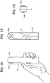
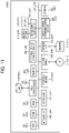
- the imaging unit 101 includes two wide-angle lenses (so-called fish-eye lenses) 102a and 102b (collectively referred to as lens 102 unless they need to be distinguished from each other), each having an angle of view of equal to or greater than 180 degrees so as to form a hemispherical image.
- the imaging unit 101 further includes the two imaging elements 103a and 103b corresponding to the lenses 102a and 102b respectively.
- the imaging elements 103a and 103b each include an imaging sensor such as a complementary metal oxide semiconductor (CMOS) sensor or a charge-coupled device (CCD) sensor, a timing generation circuit, and a group of registers.
- CMOS complementary metal oxide semiconductor
- CCD charge-coupled device
- the imaging sensor converts an optical image formed by the lenses 102a and 102b into electric signals to output image data.
- the timing generation circuit generates horizontal or vertical synchronization signals, pixel clocks and the like for the imaging sensor.
- the image processor 104 acquires image data from each of the imaging elements 103a and 103b via the parallel I/F bus and performs predetermined processing on each image data. Thereafter, the image processor 104 combines these image data to generate data of the equirectangular projection image as illustrated in FIG. 3C .
- the imaging controller 105 operates in cooperation with the CPU 111 to synchronize the time when the imaging element 103a outputs image data and the time when the imaging element 103b outputs the image data. It should be noted that, although the image capturing device 10 does not include a display in this embodiment, the image capturing device 10 may include the display.
- the microphone 108 converts sounds to audio data (signal).
- the audio processor 109 acquires the audio data output from the microphone 108 via an I/F bus and performs predetermined processing on the audio data.
- the operation unit 115 collectively refers to various operation keys, a power switch, the shutter button, and a touch panel having functions of both displaying information and receiving input from a user, which can be used in combination.
- the user operates the operation unit 115 to input various image capturing (photographing) modes or image capturing (photographing) conditions.
- the electronic compass 118 calculates an orientation of the image capturing device 10 from the Earth's magnetism to output orientation information.
- This orientation information is an example of related information, which is metadata described in compliance with Exif. This information is used for image processing such as image correction of captured images.
- the related information also includes a date and time when the image is captured by the image capturing device 10, and a data size of the image data.
- the gyro sensor 119 detects the change in angle of the image capturing device 10 (roll, pitch, yaw) with movement of the image capturing device 10.
- the change in angle is one example of related information (metadata) described in compliance with Exif. This information is used for image processing such as image correction of captured images.
- the acceleration sensor 120 detects acceleration in three axial directions.
- the image capturing device 10 calculates position (an angle with respect to the direction of gravity) of the image capturing device 10, based on the acceleration detected by the acceleration sensor 120. With the gyro sensor 119 and the acceleration sensor 120, the image capturing device 10 is able to correct tilt of images with high accuracy.
- the network I/F 121 is an interface for performing data communication, via a router or the like, using the communication network 100 such as the Internet.
- the keyboard 311 is an example of an input device including a plurality of keys for inputting characters, numerical values, various instructions, and the like.
- the pointing device 312 is an example of an input device that allows a user to select or execute a specific instruction, select a target for processing, or move a cursor being displayed.
- the input device is not limited to the keyboard 311 and the pointing device 312, and may be a touch panel, a voice input device, or the like.
- the DVD-RW drive 314 reads and writes various data from and to a DVD-RW 313, which is an example of a removable recording medium. In alternative to the DVD-RW, any recording medium may be used such as a digital versatile disc recordable (DVD-R) or Blu-ray Disc (registered trademark).
- DVD-R digital versatile disc recordable
- Blu-ray Disc registered trademark
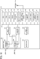
- FIG. 11 is a diagram illustrating an example hardware configuration of the communication management system 50.
- Each hardware element of the communication management system 50 is denoted by a reference numeral in 500 series.
- the communication management system 50 is implemented by one or more computers and has substantially the same configuration as that of the communication terminal 30 as illustrated in FIG. 11 , and thus the description of the hardware configuration is omitted.
- FIGs. 12 to 20 a functional configuration of the image communication system 1 is described according to the embodiment.
- FIGs. 12 and 13 are diagrams illustrating an example functional configuration of the image communication system 1 according to the embodiment.
- FIGs. 12 and 13 illustrate some of the devices and terminals illustrated in FIG. 9 , which are related to processing or operation to be described below.
- the acceptance unit 12 is implemented by the operation unit 115, which operates according to instructions of the CPU 111, and receives various selections or inputs from the user.
- the imaging unit 13 is implemented by the imaging unit 101, the image processor 104, and the imaging controller 105, each operating according to instructions of the CPU 111.
- the imaging unit 13 captures an image of an object or surroundings (for example, scenery) to obtain captured image data.
- the sound collection unit 14 is implemented by the microphone 108 and the audio processor 109, each operating according to instructions of the CPU 111.
- the sound collection unit 14 collects sounds around the image capturing device 10.
- the transmitting/receiving unit 31 (example of receiving means) is implemented by the network I/F 309, which operates according to instructions of the CPU 301, and transmits or receives various data or information to or from any other device or terminal through the communication network 100.
- the generation unit 37 is implemented by instructions of the CPU 301, and generates a predetermined-area image to be displayed on the display 306. For example, to display on the display 306 an image of a predetermined area corresponding to predetermined-area information indicating a predetermined area in an image captured by the image capturing device 10 or predetermined-area information received by the transmitting/receiving unit 31, the generation unit 37 applies perspective projection conversion to the captured image (spherical image) using the predetermined-area information to generate a predetermined-area image corresponding to the predetermined-area information.
- the communication unit 38 is implemented by the short-range communication circuit 320 that operates according to instructions of the CPU 301, and communicates with the communication unit 11 of the image capturing device 10 using short-range wireless communication technology such as NFC, Bluetooth, or WiFi.
- short-range wireless communication technology such as NFC, Bluetooth, or WiFi.
- the communication unit 38 and the transmitting/receiving unit 31 are independent from each other; however, the communication unit 38 and the transmitting/receiving unit 31 may be configured as a single unit.
- the imaging unit 41 is implemented by the camera 321 that operates according to instructions of the CPU 301, and captures an object such as scenery to acquire captured image data.
- the sound collection unit 42 is implemented by the microphone 318 and the audio input/output I/F 317, which operate according to instructions of the CPU 301, and collects sounds around the communication terminal 30.
- the storing and reading unit 39 is implemented by instructions of the CPU 301, and stores various data or information in the storage unit 3000 or reads out various data or information from the storage unit 3000.
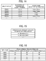
- the predetermined-area management table illustrated in FIG. 16 stores no predetermined-area information in the third row, and manages information indicating that a synchronized display direction of the predetermined-area image is not provided for the video data having the reproduction time corresponding to the time stamp "10003".
- the transmitting/receiving unit 31 receives new predetermined-area information corresponding to a time stamp of video data that has already been managed, the storing and reading unit 39 rewrites the managed predetermined-area information to the received new predetermined-area information.
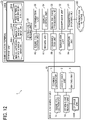
- the communication management system 50 includes a transmitting/receiving unit 51, a determination unit 52, a video recording processing unit 53, a generation unit 54, a distribution condition setting unit 55, and a storing and reading unit 59. These units are functions that are implemented by or caused to function by operating any of the hardware elements illustrated in FIG. 11 in cooperation with the instructions of the CPU 501 according to the control program for the communication management system expanded from the HD 504 to the RAM 503.
- the communication management system 50 further includes a storage unit 5000, which is implemented by the ROM 502, the RAM 503, and the HD 504 illustrated in FIG. 11 .
- the distribution condition setting unit 55 is implemented by instructions of the CPU 501, and sets distribution conditions for distributing the video data recorded by the video recording processing unit 53 to the communication terminals 30 at the respective sites. For example, the distribution condition setting unit 55 sets, in association with a time stamp indicating a reproduction time of the recorded video data, predetermined-area information corresponding to the reproduction time.
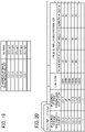
- FIG. 17 is a conceptual view illustrating an example of a session management table.
- the storage unit 5000 includes a session management DB 5001.
- the session management DB 5001 is made up of the session management table illustrated in FIG. 17 .
- the session management table a session ID and an IP address of a participant communication terminal are managed in association with each other.
- the session ID is an example of session identification information identifying a communication session for implementing image communication.
- the session ID is generated for each virtual room.
- the session ID is also managed by each communication terminal, and is used when each communication terminal selects a communication session.
- the IP address of the participant communication terminal indicates the IP address of the communication terminal 30 participating in a virtual room indicated by the session ID, which is associated with the IP address.
- the communication management system 50 manages an image data ID, an IP address of a transmission source terminal, and image type information, which are the same as those managed in the communication terminal 30, because, for example, when a new communication terminal 30 enters a virtual room, the communication management system 50 transmits information including the image type information to a communication terminal 30 that has already been in video communication and the new communication terminal 30, which has just participated in the video communication. As a result, the communication terminal 30 that has already been in the video communication and the communication terminal 30 that has just participated in the video communication do not have to transmit and receive such information including the image type information.
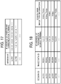
- FIG. 19 is a conceptual view illustrating an example of a video data management table.
- the storage unit 5000 includes the video data management DB 5003.
- the video data management DB 5003 is made up of the video data management table illustrated in FIG. 19 .
- an IP address of the communication terminal 30 or the image capturing device 10 from which captured image data is transmitted, and a recorded data file of video data, which is the captured image data, are managed in association with each other.
- the communication management system 50 transmits predetermined-area information corresponding to each of the time stamps, which are associated with the IP address "all", to all of the communication terminals 30 to which the video data is to be distributed, and causes all of the communication terminals 30 to display the same predetermined area.
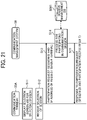
- FIG. 21 is a sequence diagram illustrating operation of processing a request for participation in a communication session, performed by the image communication system 1, according to the embodiment.
- FIG. 22 is a diagram illustrating an example of a selection screen 800 for selecting a session.
- the acceptance unit 32 receives an instruction for displaying the session selection screen.
- the display control unit 34 of the communication terminal 30A causes the display 306 to display the selection screen 800 as illustrated in FIG. 22 (S11).
- the selection screen 800 illustrated in FIG. 22 displays selection buttons 810a, 810b, and 810c, which correspond to rooms A1, B1, and B2, respectively, for selection.
- Each of the selection buttons 810a, 810b, and 810c is associated with a corresponding session ID.
- the storing and reading unit 59 of the communication management system 50 performs a process for causing the communication terminal 30A to participate in the communication session (S14). More specifically, the storing and reading unit 59 adds, in the session management DB 5001 ( FIG. 17 ), the IP address that is received at S13 to a field of the participant terminal IP address in a record of the session ID that is the same as the session ID received at S13.
- the transmitting/receiving unit 51 transmits a response to the participation request to the communication terminal 30A (S15).
- the response to the participation request includes the session ID received at S13 and the result of the participation process performed at S14.
- the communication terminal 30A receives the response to the participation request at the transmitting/receiving unit 31.
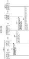
- the determination unit 35 of the communication terminal 30A determines whether a vendor ID and a product ID, which are the same as a vendor ID and a product ID of the GUID received at S31, are stored in the image capturing device management DB 3001 (see FIG. 15 ) to determine the image type (S32). More specifically, the determination unit 35 of the communication terminal 30A determines that the image capturing device 10A is an image capturing device that captures a special image (a spherical image, in this embodiment), when the same vender ID and product ID are stored in the image capturing device management DB 3001. By contrast, the determination unit 35 of the communication terminal 30A determines that the image capturing device 10A is an image capturing device that captures a general image, when the same vender ID and product ID are not stored in the image capturing device management DB 3001.
- the storing and reading unit 59 of the communication management system 50 refers to the session management DB 5001 (see FIG. 17 ) using the IP address of the transmission source terminal, which is received at S34, as a search key, to search for and read the session ID associated with the IP address (S35).
- the generation unit 54 generates a unique image data ID (S36). Then, the storing and reading unit 59 adds, in the image type management DB 5002 (see FIG. 18 ), a new record associating the session ID read at S35, the image data ID generated at S36, and the IP address of the transmission source terminal and the image type information, which are received at S34, with one another (S37).
- the transmitting/receiving unit 51 transmits the image data ID generated at S36 to the communication terminal 30A (S38).
- the communication terminal 30A receives the image data ID at the transmitting/receiving unit 31.
- the storing and reading unit 39 of the communication terminal 30A stores, in the image type management DB 3002A (see FIG. 14 ), the image data ID received at S38 in association with the IP address of the transmission source terminal (i.e., the communication terminal 30A) and the image type information, which are stored at S33 (S39).
- the transmitting/receiving unit 51 transmits the notification indicating the addition of the image type information to another IP address that is associated with the same session ID as that of the IP address of the communication terminal 30A in the session management DB 5001 (see FIG. 17 ). That is, the notification indicating the addition of the image type information is transmitted to another communication terminal 30 in the same virtual room as that of the communication terminal 30A.
- the storing and reading unit 39 of the communication terminal 30D stores, in the image type management DB 3002D (see FIG. 14 ), a new record associating the image data ID, the IP address of the transmission source terminal (i.e., the communication terminal 30A), and the image type information, which are received at S40, with one another (S41).
- the notification indicating the addition of the image type information is also transmitted to another communication terminal 30, namely, the communication terminal 30C, and is stored in the image type management DB 3002C of the communication terminal 30C. Accordingly, the communication terminals 30A, 30C, and 30D can share the same information in the image type management DBs 3002A, 3002C, and 3002D, respectively.
- FIG. 24 is a sequence diagram illustrating operation of transmitting captured image data and audio data, performed by the image communication system 1, according to the embodiment.
- FIG. 24 illustrates an example in which captured image data acquired by one image capturing device 10 is distributed to the communication terminals 30. However, similar processing is performed when a plurality of captured image data acquired by other image capturing devices 10 installed in the same site are distributed.
- the communication unit 11 of the image capturing device 10A transmits to the communication terminal 30A captured image data acquired by capturing an object or surroundings such as scenery and audio data acquired by collecting sounds (S51).
- the image capturing device 10A is capable of obtaining two hemispherical images from which a spherical image is generated, as illustrated in FIGs. 3A and 3B , the captured image data includes data of two hemispherical images.
- the communication terminal 30A receives the captured image data and the audio data at the communication unit 38.
- the transmitting/receiving unit 31 of the communication terminal 30A transmits to the communication management system 50 the captured image data and the audio data sent from the image capturing device 10A (S52). Along with the captured image data and the audio data, an image data ID identifying the captured image data, which is a transmission target, is also transmitted.
- the communication management system 50 receives the captured image data, the audio data, and the image data ID at the transmitting/receiving unit 51.
- the transmitting/receiving unit 51 of the communication management system 50 transmits the captured image data and the audio data to the communication terminals (the communication terminals 30C and 30D) participating in the same session as the session in which the communication terminal 30A is participating (S53 and S54).
- the communication terminals 30C and 30D receive the captured image data, the audio data, and the image data ID at the respective transmitting/receiving units 31.
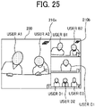
- FIG. 25 is a view illustrating an example of a display screen displayed on the communication terminal 30.
- a display screen 200 displays captured images of the respective sites, which are based on captured image data. For example, when an image captured at a predetermined site is a spherical image, the display screen 200 displays a spherical image and a predetermined-area image, which are generated from captured image data sent from the other sites.
- the images of the sites A and B are each displayed as a hemispherical image of the front side and a hemispherical image of the rear side as respectively illustrated in FIGs. 3A and 3B .
- the generation unit 37 generates a spherical image from the captured image data output from each of the image capturing devices 10A and 10B, which are capable of obtaining two hemispherical images from which a spherical image is generated, and further generates a predetermined-area image, as illustrated in FIG. 25 , a predetermined-area image that is a planar image is displayed.
- the users at the respective sites are able to change a predetermined area corresponding to a predetermined-area image in the same spherical image.
- each user at each site operates the input device, such as the pointing device 312, to allow the acceptance unit 32 to receive movement of the predetermined-area image and the display control unit 34 to shift or rotate the predetermined-area image or reduce or increase the size of the predetermined-area image.
- the image of the site A is displayed in a left display area (with the layout number "1") of the display screen 200, and the image of the site B is displayed in an upper right display area (with the layout number "2") of the display screen 200.
- the image of the site C is displayed in a middle-right display area (with the layout number "3") of the display screen 200, and the image of the site D is displayed in a lower right display area (with the layout number "4") of the display screen 200.
- the display area having the layout number "1” is a main display area, and the display areas having the layout numbers "2", "3", and "4" are sub-display areas.
- the image in the main display area and the images in the sub display areas can be changed in each communication terminal. In general, an image in which a main person in the video communication is included is displayed in the main display area at each site.
- spherical icons 210a and 210b are examples of a special image identification icon for identifying a predetermined-area image representing the predetermined area T, which is a portion of the spherical image.
- the spherical icons 210a and 210b may be displayed at any position such as an upper left corner, a lower left corner, or a lower right corner, instead of the upper right corner.
- the type of the spherical icons 210a and 210b is not limited to that illustrated in FIG. 25 .
- characters such as "spherical image" may be used, or a combination of an icon and characters may be used.
- FIG. 26 is a flowchart illustrating an example of a video data recording process.
- the video data recording process illustrated in FIG. 26 is executed when the communication management system 50 receives captured image data, as in S52 in FIG. 24 .
- the determination unit 52 of the communication management system 50 determines whether the data transmitted from the communication terminal 30 (e.g., the communication terminal 30A illustrated in FIG. 24 ) from which the captured image data and the like are transmitted is video data.
- the determination unit 52 determines that video data is received by the transmitting/receiving unit 51 (YES at S71)
- the process proceeds to S72.
- the video recording processing unit 53 stores the data file of the video data received by the transmitting/receiving unit 51 in the video data management DB 5003 (see FIG. 19 ) (S72).
- the video recording processing unit 53 stores the IP address of the transmission source of the received video data and a recorded data file (e.g., a file name) of the received video data in the video data management DB 5003 in association with each other.
- the video recording processing unit 53 combines captured image data and audio data transmitted from the communication terminal 30 at each site to obtain a single recorded data file for each site, and stores the recorded data files for the respective sites in the video data management DB 5003.
- the storing and reading unit 59 stores the predetermined-area information received by the transmitting/receiving unit 51 in the predetermined-area management DB 5004 (see FIG. 20 ) (S74).
- the storing and reading unit 59 stores the received predetermined-area information in the predetermined-area management DB 5004 in association with the IP addresses of the transmission source and the transmission destination of the video data corresponding to the received predetermined-area information and a time stamp indicating the reproduction time of the video data corresponding to the received predetermined-area information.
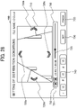
- FIG. 28 is a view illustrating an example of the distribution condition setting screen 700.
- the distribution condition setting screen 700 illustrated in FIG. 28 is a screen for setting a predetermined area to be displayed on the communication terminal 30 when video data is distributed to each site during reproduction of recorded video data.
- the distribution condition setting screen 700 includes an image display area 710, a reproduction position display area 730, a predetermined-area information display area 740, a setting button 750, and a "finish" button 755.
- the image display area 710 displays an image based on video data being reproduced.
- the reproduction position display area 730 displays a reproduction position of the video data.
- the predetermined-area information display area 740 indicates a predetermined area corresponding to a display direction specified in the image display area 710.
- the setting button 750 is pressed to set distribution conditions.
- the "finish" button 755 is pressed to finish the setting of distribution conditions.
- the image display area 710 includes display direction change buttons 720 (720a, 720b, 720c, and 720d) for changing the display direction for the video data.
- the user A1 selects a desired one of the display direction change buttons 720 to change the display direction of the image to be displayed in the image display area 710.
- the reproduction position display area 730 includes a play button 731, a pause button 732, and a slider 735.
- the play button 731 is pressed to reproduce the video data.
- the pause button 732 is pressed to stop the reproduction of the video data.
- the slider 735 indicates a reproduction history (reproduction position) relative to the entire reproduction time.
- the slider 735 forms a seek bar.
- the seek bar is an operation area for designating a reproduction position of the video data.
- the seek bar displays the reproduction position of the video data.
- the slider 735 allows the user A1 to visually grasp, for example, which portion of the video data is being reproduced from the beginning to the end of the video data. Further, for example, the user A1 can move the slider 735 using the input device, such as the pointing device 312, to reproduce the video data from a desired reproduction position.
- the predetermined-area information display area 740 presents predetermined-area information corresponding to the predetermined-area image displayed in the image display area 710.
- values of the predetermined area corresponding to the predetermined-area image being displayed are changed as appropriate by changing the display direction of the image to be displayed in the image display area 710 in response to, for example, the user A1 selecting and moving any one of the display direction change buttons 720.
- the user A1 may manually input the values of the predetermined area to be displayed in the predetermined-area information display area 740 to change the display direction of the image to be displayed in the image display area 710.
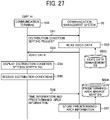
- the acceptance unit 32 of the communication terminal 30A receives input of distribution conditions in response to the user A1 selecting any one of the display direction change buttons 720 or inputting numerical values in the predetermined-area information display area 740 and pressing the setting button 750 (S95). In this case, the acceptance unit 32 receives predetermined-area information selected or input by the user A1 as distribution conditions. Then, the transmitting/receiving unit 31 of the communication terminal 30A transmits to the communication management system 50 the predetermined-area information input at S95 and time information indicating the reproduction time of the video data corresponding to the input predetermined-area information (S96). The communication management system 50 receives the predetermined-area information and the time information, which are transmitted from the communication terminal 30A, at the transmitting/receiving unit 51.
- the distribution condition setting unit 55 of the communication management system 50 stores the time stamp corresponding to the predetermined-area information and the time information received at S96 in the predetermined-area management DB 5004 (see FIG. 20 ) in association with the IP address of the communication terminal 30A from which the distribution condition setting request received at S91 is transmitted (S97).
- the distribution condition setting unit 55 sets the IP address of the image transmission destination, which is to be stored in association with the received predetermined-area information, to "all".
- the distribution condition setting unit 55 rewrites the managed predetermined-area information to the received new predetermined-area information.
- the distribution condition setting unit 55 may use the IP address of the specific image transmission destination that has already existed, as is, without setting the IP address of the image transmission source to "all".
- the distribution condition setting unit 55 may be configured to prompt the user A1 to input the IP address of the image transmission destination using the distribution condition setting screen 700 illustrated in FIG. 28 to store the IP address of the specific image transmission destination in association with the received predetermined-area information.
- FIG. 29 is a sequence diagram illustrating an example of a recorded video data distribution process.
- the example illustrated in FIG. 29 presents a description of operation of distributing video data recorded by the communication management system 50 to the communication terminal 30C at the site C.
- the storing and reading unit 59 of the communication management system 50 reads, from the predetermined-area management DB 5004 (see FIG. 20 ), predetermined-area information corresponding to the video data specified by the video distribution request received at S111 (S112).
- the storing and reading unit 59 reads the intended predetermined-area information and the time stamp associated with the predetermined-area information.
- the transmitting/receiving unit 51 transmits, to the communication terminal 30C from which the request is transmitted, a set of the predetermined-area information read at S112 and time information indicating a reproduction time identified by the time stamp associated with the predetermined-area information (S113).
- the communication terminal 30C receives the set of the predetermined-area information and the time information, which is transmitted from the communication management system 50, at the transmitting/receiving unit 31.
- the communication management system 50 may perform the processing of S112 and S113 at once on all of the target pieces of predetermined-area information stored in the predetermined-area management DB 5004, or may sequentially perform the processing of S112 and S113 every certain period (e.g., 30 seconds) in accordance with the reproduction time of the video data.
- the storing and reading unit 59 of the communication management system 50 reads, from the video data management DB 5003 (see FIG. 19 ), the recorded data file of the video data specified by the video distribution request received at S111 (S115). Then, the transmitting/receiving unit 51 sequentially transmits the captured image data and the audio data of the video data, based on the recorded data file read at S115, to the communication terminal 30C from which the request is transmitted (S116). Along with the captured image data and the audio data, an image data ID identifying the captured image data, which is a transmission target, is also transmitted. The communication terminal 30C receives the captured image data and the audio data transmitted from the communication management system 50 at the transmitting/receiving unit 31.
- the display control unit 34 of the communication terminal 30C reproduces the video data received at S116 to display the captured image (S117).
- the communication management system 50 may simultaneously distribute the recorded data files to the communication terminal 30C, and the communication terminal 30C may display the recorded data files in combination when viewing them.
- the communication management system 50 may distribute data to each individual communication terminal 30 or synchronously distribute data to a plurality of communication terminals 30.
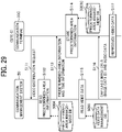
- FIG. 30 is a flowchart illustrating an example process for reproducing video data on the communication terminal 30C.
- the following processing is performed in reproducing video data.
- the generation unit 37 of the communication terminal 30C applies perspective projection conversion using the predetermined-area information received at S131 to generate a predetermined-area image (S134).
- the communication terminal 30C can generate the predetermined-area image corresponding to the distribution conditions set by the communication management system 50.
- the display control unit 34 causes the display 306 to display the predetermined-area image generated at S134 (S135).
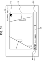
- FIG. 31 is a view illustrating an example of a display screen displayed on the communication terminal 30C when a synchronized display direction is provided.
- the example illustrated in FIG. 31 presents a display screen 400 on which an image based on video data corresponding to a synchronized display direction is displayed in a predetermined reproduction time.
- the display screen 400 includes a predetermined-area image 410, a synchronization completion icon 415, and a reproduction position display area 430.
- the predetermined-area image 410 is generated from the video data at S134.
- the synchronization completion icon 415 indicates that a synchronized display direction is provided.
- the reproduction position display area 430 displays a reproduction position of the video data.
- the reproduction position display area 430 includes a play button 431, a pause button 432, and a slider 435.
- the play button 431 is pressed to reproduce the video data.
- the pause button 432 is pressed to stop the reproduction of the video data.
- the slider 435 indicates a reproduction history (reproduction position) relative to the entire reproduction time.
- the play button 431, the pause button 432, and the slider 435 have configurations similar to those of the play button 731, the pause button 732, and the slider 735 illustrated in FIG. 28 .
- the communication management system 50 causes the communication terminal 30C to display a predetermined-area image corresponding to distribution conditions set by the communication management system 50, and enables the communication terminal 30C to display an image based on video data corresponding to a synchronized display direction.
- the user C1 is not allowed to change the display direction while viewing the predetermined-area image 410 displayed on the display screen 400.
- the synchronization completion icon 415 displayed on the display screen 400 allows the user C1 to grasp that the display direction for the video data is not changeable.
- the predetermined-area information transmitted from the communication management system 50 to the communication terminal 30C may be information transmitted from the communication terminal 30 for viewing at the time of live distribution of the video data and stored in the communication management system 50, as illustrated at S74 in FIG. 26 , or may be information stored in the communication management system 50 in accordance with the distribution condition setting process, as illustrated at S97 in FIG. 27 .
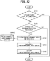
- FIG. 32 is a flowchart illustrating an example process for changing a display direction on the communication terminal 30C.
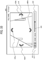
- FIG. 33 is a view illustrating an example of a display screen displayed on the communication terminal 30C when no synchronized display direction is provided.
- the display screen 400 illustrated in FIG. 33 includes a predetermined-area image 410, which is an image of any predetermined area of the video data received at S116 in FIG. 29 , display direction change buttons 420 (420a, 420b, 420c, and 420d) for changing the display direction for the video data, and a reproduction position display area 430 that displays a reproduction position of the video data.
- the reproduction position display area 430 has a configuration similar to that illustrated in FIG. 31 .
- the process proceeds to S153.
- the acceptance unit 32 of the communication terminal 30C has not received a change of the display direction (NO at S152)
- the process ends.
- the storing and reading unit 39 of the communication terminal 30C stores predetermined-area information indicating a predetermined area corresponding to the display direction received at S152 in the predetermined-area management DB 3003C in association with a time stamp indicating the reproduction time of the video data corresponding to the predetermined-area information (S153).
- the generation unit 37 of the communication terminal 30C applies perspective projection conversion using the predetermined-area information stored at S153 to generate a predetermined-area image (S154). Then, the display control unit 34 causes the display 306 to display the predetermined-area image generated at S154 (S155).
- the image communication system 1 reflects a synchronized display direction for the recorded video data such that a viewer is allowed to operate a display direction for the video data as desired in a certain time period, whereas an image corresponding to the synchronized display direction is viewed in some other time period. Accordingly, the image communication system 1 can cause the communication terminal 30 to display an image corresponding to an appropriate display direction in accordance with the reproduction time of video data captured at a different site.
- the communication management system 50 sets, for a recorded data file of video data transmitted from the image capturing device 10 or the communication terminal 30 at each site, predetermined-area information corresponding to a reproduction time of the video data for video recording and distribution to allow the communication terminal 30 to display an image based on the recorded video data in a synchronized display direction.
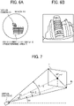
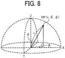
- the predetermined area T is specified by predetermined-area information indicating an imaging direction and an angle of view of the virtual camera IC in a three-dimensional virtual space containing the spherical image CE, but the present disclosure is not limited thereto.
- the predetermined area T may be specified by predetermined point information indicating the center point CP or an arbitrary point of four corners of the predetermined area T having a rectangular shape in FIG. 7 . In such a case, it is assumed that an angle of view is constant.
- a captured image (whole image) is a three-dimensional spherical panoramic image, as an example of a spherical image.
- the captured image is a two-dimensional panoramic image, as an example of a spherical image.
- Processing circuitry includes a programmed processor, such as a processor including circuitry.
- a processing circuit also includes devices such as an application specific integrated circuit (ASIC), a digital signal processor (DSP), a field programmable gate array (FPGA), a system on a chip (SOC), a graphics processing unit (GPU), and conventional circuit components arranged to perform the recited functions.
- ASIC application specific integrated circuit
- DSP digital signal processor
- FPGA field programmable gate array
- SOC system on a chip
- GPU graphics processing unit
- Each of the tables of the above-described embodiment may be generated by learning effect of machine learning.
- the data of each related item may be classified by the machine learning.
- the machine learning is defined as a technology that makes a computer acquire human-like learning ability.
- the machine learning refers to a technology in which a computer autonomously generates an algorithm required for determination such as data identification from learning data loaded in advance and applies the generated algorithm to new data to make a prediction. Any suitable learning method is applied for machine learning, for example, any one of supervised learning, unsupervised learning, semi-supervised learning, reinforcement learning, and deep learning, or a combination of two or more those learning.
- the present invention can be implemented in any convenient form, for example using dedicated hardware, or a mixture of dedicated hardware and software.
- the present invention may be implemented as computer software implemented by one or more networked processing apparatuses.
- the processing apparatuses include any suitably programmed apparatuses such as a general purpose computer, a personal digital assistant, a Wireless Application Protocol (WAP) or third-generation (3G)-compliant mobile telephone, and so on. Since the present invention can be implemented as software, each and every aspect of the present invention thus encompasses computer software implementable on a programmable device.
- the computer software can be provided to the programmable device using any conventional carrier medium (carrier means).
- the carrier medium includes a transient carrier medium such as an electrical, optical, microwave, acoustic or radio frequency signal carrying the computer code.
- transient medium is a Transmission Control Protocol/Internet Protocol (TCP/IP) signal carrying computer code over an IP network, such as the Internet.
- the carrier medium may also include a storage medium for storing processor readable code such as a floppy disk, a hard disk, a compact disc read-only memory (CD-ROM), a magnetic tape device, or a solid state memory device.
Landscapes
- Engineering & Computer Science (AREA)
- Multimedia (AREA)
- Signal Processing (AREA)
- Databases & Information Systems (AREA)
- Human Computer Interaction (AREA)
- General Engineering & Computer Science (AREA)
- Studio Devices (AREA)
- Two-Way Televisions, Distribution Of Moving Picture Or The Like (AREA)
- Closed-Circuit Television Systems (AREA)
Applications Claiming Priority (1)
| Application Number | Priority Date | Filing Date | Title |
|---|---|---|---|
| JP2021094184A JP7694166B2 (ja) | 2021-06-04 | 2021-06-04 | 通信端末、画像通信システム、画像表示方法およびプログラム |
Publications (1)
| Publication Number | Publication Date |
|---|---|
| EP4099705A1 true EP4099705A1 (en) | 2022-12-07 |
Family
ID=82156585
Family Applications (1)
| Application Number | Title | Priority Date | Filing Date |
|---|---|---|---|
| EP22176038.2A Pending EP4099705A1 (en) | 2021-06-04 | 2022-05-30 | Communication terminal, image communication system, method for displaying image, and carrier means |
Country Status (3)
| Country | Link |
|---|---|
| US (3) | US11863871B2 (enExample) |
| EP (1) | EP4099705A1 (enExample) |
| JP (2) | JP7694166B2 (enExample) |
Families Citing this family (4)
| Publication number | Priority date | Publication date | Assignee | Title |
|---|---|---|---|---|
| JP2023121637A (ja) | 2022-02-21 | 2023-08-31 | 株式会社リコー | 情報処理システム、通信システム、画像送信方法、プログラム |
| JP2023140922A (ja) * | 2022-03-23 | 2023-10-05 | 株式会社リコー | 表示端末、情報処理システム、通信システム、表示方法、情報処理方法、通信方法、及びプログラム |
| JP2023140923A (ja) | 2022-03-23 | 2023-10-05 | 株式会社リコー | 表示端末、情報処理システム、通信システム、表示方法、情報処理方法、通信方法、及びプログラム |
| EP4436191A1 (en) * | 2023-03-22 | 2024-09-25 | Ricoh Company, Ltd. | Display terminal, communication system, display method, and carrier means |
Citations (5)
| Publication number | Priority date | Publication date | Assignee | Title |
|---|---|---|---|---|
| JP2016025640A (ja) | 2014-07-24 | 2016-02-08 | エイオーエフ イメージング テクノロジー リミテッド | 情報処理装置、情報処理方法およびプログラム |
| US20200296284A1 (en) * | 2019-03-11 | 2020-09-17 | Ricoh Company, Ltd. | Image communication system, image capturing device, communication terminal, and mode switching method |
| US20200296302A1 (en) * | 2019-03-15 | 2020-09-17 | Ricoh Company, Ltd. | Image capturing device, image processing system, and image processing method |
| US20200374463A1 (en) * | 2017-10-26 | 2020-11-26 | Ricoh Company, Ltd. | Method of displaying wide-angle image, image display system, and information processing apparatus |
| US20200389640A1 (en) * | 2018-04-11 | 2020-12-10 | Lg Electronics Inc. | Method and device for transmitting 360-degree video by using metadata related to hotspot and roi |
Family Cites Families (22)
| Publication number | Priority date | Publication date | Assignee | Title |
|---|---|---|---|---|
| JP2001218194A (ja) * | 1999-11-15 | 2001-08-10 | Canon Inc | 撮像装置及び画像配信システムの制御方法、撮像装置の制御装置、画像配信システム及び装置、データ配信装置及び方法 |
| JP2014112302A (ja) * | 2012-12-05 | 2014-06-19 | Ricoh Co Ltd | 所定領域管理システム、通信方法、及びプログラム |
| JP6548203B2 (ja) * | 2013-03-18 | 2019-07-24 | 任天堂株式会社 | 情報処理プログラム、情報処理装置、情報処理システム、および、パノラマ動画表示方法 |
| JP2016010010A (ja) * | 2014-06-24 | 2016-01-18 | 日立マクセル株式会社 | 音声入出力機能付き撮像装置およびテレビ会議システム |
| JP6344723B2 (ja) * | 2015-07-14 | 2018-06-20 | パナソニックIpマネジメント株式会社 | 映像表示システム、映像表示装置及び映像表示方法 |
| JP6816465B2 (ja) * | 2016-11-16 | 2021-01-20 | 株式会社リコー | 画像表示システム、通信システム、画像表示方法、及びプログラム |
| JP7151316B2 (ja) | 2017-09-25 | 2022-10-12 | 株式会社リコー | 通信端末、画像通信システム、表示方法、及びプログラム |
| JP7095361B2 (ja) | 2018-03-29 | 2022-07-05 | 株式会社リコー | 通信端末、画像通信システム、表示方法、及びプログラム |
| JP7164831B2 (ja) | 2018-03-30 | 2022-11-02 | 株式会社リコー | 通信管理システム、通信システム、通信方法、及びプログラム |
| JP2019180027A (ja) | 2018-03-30 | 2019-10-17 | 株式会社リコー | 通信端末、画像通信システム、表示方法、及びプログラム |
| US10554883B2 (en) | 2018-03-30 | 2020-02-04 | Ricoh Company, Ltd. | VR system, communication method, and non-transitory computer-readable medium |
| US10764513B2 (en) | 2018-07-31 | 2020-09-01 | Ricoh Company, Ltd. | Communication terminal, image data communication system, and communication method |
| US20200186407A1 (en) | 2018-11-30 | 2020-06-11 | Kenichiro Morita | Communication terminal, image network system, display method, and program |
| JP7326789B2 (ja) * | 2019-03-19 | 2023-08-16 | 株式会社リコー | 通信端末、画像通信システム、表示方法、及びプログラム |
| JP7346975B2 (ja) | 2019-07-25 | 2023-09-20 | 株式会社リコー | 通信端末、画像通信システム、表示方法、及びプログラム |
| JP7327008B2 (ja) | 2019-09-02 | 2023-08-16 | 株式会社リコー | 撮影装置、通信システム、通信方法およびプログラム |
| JP7368707B2 (ja) | 2019-09-24 | 2023-10-25 | 株式会社リコー | 画像処理方法、プログラム、画像処理装置および画像処理システム |
| JP7400407B2 (ja) * | 2019-11-28 | 2023-12-19 | 株式会社リコー | 通信端末、撮影システム、画像処理方法及びプログラム |
| JP7625808B2 (ja) | 2020-08-31 | 2025-02-04 | 株式会社リコー | 画像通信システムおよび画像表示方法 |
| JP7533061B2 (ja) | 2020-09-18 | 2024-08-14 | 株式会社リコー | 通信端末、画像通信システム、画像表示方法およびプログラム |
| JP7600595B2 (ja) | 2020-09-30 | 2024-12-17 | 株式会社リコー | 通信管理装置、画像通信システム、通信管理方法及びプログラム |
| JP7604829B2 (ja) | 2020-09-30 | 2024-12-24 | 株式会社リコー | 画像通信システム、通信管理装置、通信管理方法及びプログラム |
-
2021
- 2021-06-04 JP JP2021094184A patent/JP7694166B2/ja active Active
-
2022
- 2022-05-30 EP EP22176038.2A patent/EP4099705A1/en active Pending
- 2022-06-03 US US17/831,462 patent/US11863871B2/en active Active
-
2023
- 2023-11-21 US US18/515,313 patent/US12389120B2/en active Active
-
2025
- 2025-06-06 JP JP2025094579A patent/JP2025122244A/ja active Pending
- 2025-07-16 US US19/270,662 patent/US20250343994A1/en active Pending
Patent Citations (5)
| Publication number | Priority date | Publication date | Assignee | Title |
|---|---|---|---|---|
| JP2016025640A (ja) | 2014-07-24 | 2016-02-08 | エイオーエフ イメージング テクノロジー リミテッド | 情報処理装置、情報処理方法およびプログラム |
| US20200374463A1 (en) * | 2017-10-26 | 2020-11-26 | Ricoh Company, Ltd. | Method of displaying wide-angle image, image display system, and information processing apparatus |
| US20200389640A1 (en) * | 2018-04-11 | 2020-12-10 | Lg Electronics Inc. | Method and device for transmitting 360-degree video by using metadata related to hotspot and roi |
| US20200296284A1 (en) * | 2019-03-11 | 2020-09-17 | Ricoh Company, Ltd. | Image communication system, image capturing device, communication terminal, and mode switching method |
| US20200296302A1 (en) * | 2019-03-15 | 2020-09-17 | Ricoh Company, Ltd. | Image capturing device, image processing system, and image processing method |
Non-Patent Citations (2)
| Title |
|---|
| HUANG HAO-JUAN HANK1258 CS05G@NCTU EDU TW ET AL: "Director-360: Introducing Camera Handling to 360 Cameras", PROCEEDINGS OF THE 2020 ACM SIGSIM CONFERENCE ON PRINCIPLES OF ADVANCED DISCRETE SIMULATION, ACMPUB27, NEW YORK, NY, USA, 5 October 2020 (2020-10-05), pages 1 - 11, XP058729029, ISBN: 978-1-4503-7592-4, DOI: 10.1145/3379503.3403550 * |
| YAXIAN BAI ET AL: "[OMAF] Signalling of ROI for Viewport-driven Interactivity", no. m52264, 11 January 2020 (2020-01-11), XP030224859, Retrieved from the Internet <URL:http://phenix.int-evry.fr/mpeg/doc_end_user/documents/129_Brussels/wg11/m52264-v2-m52264-v2SignallingofROIforViewport-drivenInteractivity.zip m52264-v2 Signalling of ROI for Viewport-driven Interactivity.docx> [retrieved on 20200111] * |
Also Published As
| Publication number | Publication date |
|---|---|
| JP2025122244A (ja) | 2025-08-20 |
| US20250343994A1 (en) | 2025-11-06 |
| JP7694166B2 (ja) | 2025-06-18 |
| US20240089603A1 (en) | 2024-03-14 |
| US11863871B2 (en) | 2024-01-02 |
| US20220394178A1 (en) | 2022-12-08 |
| US12389120B2 (en) | 2025-08-12 |
| JP2022186117A (ja) | 2022-12-15 |
Similar Documents
| Publication | Publication Date | Title |
|---|---|---|
| EP3461124B1 (en) | Communication terminal, image communication system, display control method, and carrier means | |
| USRE50640E1 (en) | Communication terminal, image communication system, and display control method | |
| EP3346702B1 (en) | Communication terminal, image communication system, communication method, and carrier means | |
| US10764513B2 (en) | Communication terminal, image data communication system, and communication method | |
| US10944619B2 (en) | Communication terminal, image communication system, and display control method | |
| JP6992338B2 (ja) | 通信システム、通信管理方法、プログラム、システム及び通信方法 | |
| JP6907861B2 (ja) | 通信端末、画像通信システム、表示方法、及びプログラム | |
| US10721116B2 (en) | Communication terminal, method for controlling display of image, and non-transitory computer-readable storage medium | |
| EP4099705A1 (en) | Communication terminal, image communication system, method for displaying image, and carrier means | |
| US11743590B2 (en) | Communication terminal, image communication system, and method for displaying image | |
| EP3962090A1 (en) | Communication terminal, image communication system, method for displaying image, and carrier means | |
| EP3989539B1 (en) | Communication management apparatus, image communication system, communication management method, and carrier means | |
| EP4064691A1 (en) | Communication management device, image communication system, communication management method, and carrier means | |
| US11736802B2 (en) | Communication management apparatus, image communication system, communication management method, and recording medium | |
| JP7017045B2 (ja) | 通信端末、表示方法、及びプログラム | |
| JP2020155847A (ja) | 通信端末、画像通信システム、表示方法、及びプログラム | |
| JP7371369B2 (ja) | 通信端末および画像通信システム |
Legal Events
| Date | Code | Title | Description |
|---|---|---|---|
| PUAI | Public reference made under article 153(3) epc to a published international application that has entered the european phase |
Free format text: ORIGINAL CODE: 0009012 |
|
| STAA | Information on the status of an ep patent application or granted ep patent |
Free format text: STATUS: REQUEST FOR EXAMINATION WAS MADE |
|
| 17P | Request for examination filed |
Effective date: 20220530 |
|
| AK | Designated contracting states |
Kind code of ref document: A1 Designated state(s): AL AT BE BG CH CY CZ DE DK EE ES FI FR GB GR HR HU IE IS IT LI LT LU LV MC MK MT NL NO PL PT RO RS SE SI SK SM TR |