EP4099423A1 - Method for manufacturing electrode plate for secondary battery, and electrode plate for secondary battery - Google Patents
Method for manufacturing electrode plate for secondary battery, and electrode plate for secondary battery Download PDFInfo
- Publication number
- EP4099423A1 EP4099423A1 EP21886571.5A EP21886571A EP4099423A1 EP 4099423 A1 EP4099423 A1 EP 4099423A1 EP 21886571 A EP21886571 A EP 21886571A EP 4099423 A1 EP4099423 A1 EP 4099423A1
- Authority
- EP
- European Patent Office
- Prior art keywords
- electrode
- adhesive film
- current collector
- collector sheet
- electrode current
- Prior art date
- Legal status (The legal status is an assumption and is not a legal conclusion. Google has not performed a legal analysis and makes no representation as to the accuracy of the status listed.)
- Granted
Links
Images


Classifications
-
- H—ELECTRICITY
- H01—ELECTRIC ELEMENTS
- H01M—PROCESSES OR MEANS, e.g. BATTERIES, FOR THE DIRECT CONVERSION OF CHEMICAL ENERGY INTO ELECTRICAL ENERGY
- H01M4/00—Electrodes
- H01M4/02—Electrodes composed of, or comprising, active material
- H01M4/04—Processes of manufacture in general
- H01M4/0402—Methods of deposition of the material
-
- H—ELECTRICITY
- H01—ELECTRIC ELEMENTS
- H01M—PROCESSES OR MEANS, e.g. BATTERIES, FOR THE DIRECT CONVERSION OF CHEMICAL ENERGY INTO ELECTRICAL ENERGY
- H01M4/00—Electrodes
- H01M4/02—Electrodes composed of, or comprising, active material
- H01M4/04—Processes of manufacture in general
- H01M4/0402—Methods of deposition of the material
- H01M4/0404—Methods of deposition of the material by coating on electrode collectors
-
- H—ELECTRICITY
- H01—ELECTRIC ELEMENTS
- H01M—PROCESSES OR MEANS, e.g. BATTERIES, FOR THE DIRECT CONVERSION OF CHEMICAL ENERGY INTO ELECTRICAL ENERGY
- H01M4/00—Electrodes
- H01M4/02—Electrodes composed of, or comprising, active material
- H01M4/13—Electrodes for accumulators with non-aqueous electrolyte, e.g. for lithium-accumulators; Processes of manufacture thereof
- H01M4/139—Processes of manufacture
-
- Y—GENERAL TAGGING OF NEW TECHNOLOGICAL DEVELOPMENTS; GENERAL TAGGING OF CROSS-SECTIONAL TECHNOLOGIES SPANNING OVER SEVERAL SECTIONS OF THE IPC; TECHNICAL SUBJECTS COVERED BY FORMER USPC CROSS-REFERENCE ART COLLECTIONS [XRACs] AND DIGESTS
- Y02—TECHNOLOGIES OR APPLICATIONS FOR MITIGATION OR ADAPTATION AGAINST CLIMATE CHANGE
- Y02E—REDUCTION OF GREENHOUSE GAS [GHG] EMISSIONS, RELATED TO ENERGY GENERATION, TRANSMISSION OR DISTRIBUTION
- Y02E60/00—Enabling technologies; Technologies with a potential or indirect contribution to GHG emissions mitigation
- Y02E60/10—Energy storage using batteries
Definitions
- the present invention relates to a method for manufacturing an electrode plate for a secondary battery.
- the present invention also relates to an electrode plate for a secondary battery, which is manufactured by the method for manufacturing the electrode plate.
- lithium secondary batteries are widely used as an energy source for various electronic products as well as various mobile devices because of their high energy density and high operating voltage and excellent storage and lifetime characteristics.
- Electrodes (positive electrode and negative electrode) constituting the electrode assembly generate electric current through ion exchange, and each of the positive electrode and the negative electrode is manufactured as an electrode substrate, which is obtained by applying an electrode slurry on the surface of a current collector made of an aluminum or copper film and drying the electrode slurry, is tab-processed and is cut in an appropriate size.
- the electrode slurry is applied on the surface of the current collector in a form in which a solvent is mixed with an active material, and is manufactured as an electrode substrate.
- the electrode substrate is dried to allow the electrode active material to be hardened on the surface of the current collector by evaporating the solvent of the electrode slurry.
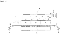
- FIG. 1 is a schematic diagram of a heat drying device for drying an electrode substrate.
- an electrode substrate 2 which is obtained as an electrode slurry has been applied on the surface of the current collector sheet 2a through a coater 7, is made to pass through an electrode oven 4 by a roller 6 to be heat-dried, which is then wound on the winding roller 1b.
- the electrode oven 4 has one or more drying chambers 4a, 4b and 4c, and the temperature of each drying chamber is controlled by heat generated in a heater 5.
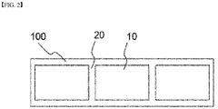
- FIG. 2 illustrates a sequential pattern of an electrode current collector sheet.
- the portion where the electrode slurry has been coated (coated part 10) and the portion where the electrode slurry has not been coated (non-coated part 20) are alternatively arranged on the current collector sheet 100.
- the non-coated part 20 is formed because the surface of the exposed electrode current collector sheet (metal) is necessary to form a terminal for connecting a positive electrode to a negative electrode at the time of later forming an electrode assembly.
- a tab may be formed on the non-coated part 20 through a later notch process, etc.
- an intermittent or discontinuous coating job in which the start and stop of the electrode slurry discharge are repeated while moving the coater or the current collector according to the pattern of the coated part 10 or the non-coated part 20, was performed.
- the coating speed is relatively slow, the pattern can be accurately formed to some extent by such a discontinuous coating job, but the productivity may decrease because the working speed is significantly slow.
- non-coated parts 20 formed between the coated parts 10 are formed in the width direction of the electrode plate as shown in FIG. 2 . Since the electrode slurry is not applied on the non-coated part 20, it does not contribute to the increase in battery capacity or energy density.
- an aspect of the present invention provides a method for manufacturing an electrode plate for a secondary battery, which can improve the coating speed by consecutively coating an electrode slurry on an electrode current collector sheet.
- another aspect of the present invention provides a method for manufacturing an electrode plate for a secondary battery, which can efficiently form an electrode pattern on an electrode by simply peeling off a non-coated part on an electrode current collector.
- another aspect of the present invention provides a method for manufacturing an electrode plate for a secondary battery, which can increase the battery capacity and energy density by enlarging the electrode-slurry-coated part.
- the present invention relates to an electrode plate for a secondary battery, which is manufactured by the above manufacturing method and can increase the battery capacity and energy density.
- a method for manufacturing an electrode plate for a secondary battery of the present invention for solving the above problems is a method for manufacturing an electrode plate by performing a pattern-coating to have a coated part, on which an electrode slurry has been coated, and a non-coated part, on which the electrode slurry has not been coated, on an electrode current collector sheet, including: attaching at least one adhesive films on at least one portion of the non-coated part on the electrode current collector sheet; consecutively coating an electrode slurry on the electrode current collector sheet including the adhesive-film-attached parts; heating and drying the electrode slurry; and peeling the adhesive film from the electrode current collector sheet and retrieving the adhesive film.
- an adhesive force of the adhesive film is reduced by the heating and drying of the electrode slurry, so that the adhesive film can be removed from the electrode current collector sheet during the peeling and retrieving, and as the adhesive film is removed, a surface of the electrode current collector sheet is exposed.
- the adhesive force of the adhesive film is reduced by heat during the heating and drying of the electrode slurry.
- the adhesive film includes a filler which expands in volume by heat.
- the filler may expand in a temperature of 80°C or higher, and preferably in a temperature between 100 and 200°C.
- the adhesive film may be peeled off from the surface of the electrode current collector sheet by adsorbing the adhesive film.
- the adhesive film may be peeled off by vacuum-adsorbing the adhesive film by using a vacuum adsorption device.
- the adhesive film may be peeled off by adsorbing the adhesive film onto an adhesive roller having an outer circumference on which an adhesive tape has been attached.
- the adhesive film may be peeled off by adsorbing the electrode current collector sheet while moving along an upper surface of the electrode current collector sheet.
- the surface of the electrode current collector sheet may be pressed to be flat after removing the adhesive film.
- the pattern on the electrode current collector sheet may be adjusted by adjusting at least one of the number, the size and the shape of the adhesive film, and the location where the adhesive film is attached.
- an electrode plate for a secondary battery may be provided by the above method.
- the electrode plate comprising an electrode current collector sheet including at least one coated part, on which an electrode slurry has been coated, and at least one non-coated part, on which the electrode slurry has not been coated, on an electrode current collector sheet.
- the non-coated part is positioned along a longitudinal direction of the electrode current collector sheet at regular intervals, the non-coated part is formed to be spaced apart from each other along a width direction of the electrode current collector sheet, and the coated part is formed on at least portion other than the non-coated part.
- the present invention it is possible to significantly improve the coating speed of the electrode slurry by consecutively forming an electrode pattern.
- the present invention it is possible to increase the battery capacity and energy density by enlarging the electrode-slurry-coated part by forming the non-coated part at only desired places on the electrode current collector.
- the adhesive film for forming a non-coated part pattern on the electrode current collector can be consecutively peeled off while moving along the surface of the electrode current collector sheet, which is an advantage.
- the present invention is devised to improve a conventional a discontinuous pattern coating technology (see FIG. 2 ) which forms a coated part, on which an electrode slurry discharged from a coater is applied in the process of moving the electrode current collector sheet, and forms a non-coated part without an electrode slurry by stopping the discharge of the electrode slurry.
- a main feature of the present invention is in attaching an adhesive film on a portion where a non-coated part is to be formed in order to consecutively perform a discontinuous pattern coating.
- an electrode slurry is consecutively coated on the electrode current collector sheet including the adhesive-film-attached portion.
- an electrode slurry is applied on the upper portion of the adhesive film. What is important is whether it is possible to efficiently peel off and retrieve the adhesive film, on which an electrode slurry has been applied. When the peeling and retrieving process of the adhesive film becomes difficult, it is not possible to appropriately form a non-coated part. As such, the technical significance of the converting the discontinuous coating into a continuous coating significantly decreases.
- the present invention adopts a means which makes the peeling of the adhesive film easy by naturally reducing the adhesive force of the adhesive film through a heat-drying process of the electrode slurry.
- the adhesive force of the adhesive film is not reduced by a separate heating or cooling process after the heat-drying process of the electrode slurry, but the adhesive force of the adhesive film can be reduced by high temperature heat applied during the heat-drying process of the electrode slurry.
- a series of process flows of the consecutive coating process-heat-drying process of FIG. 1 are not interfered. Accordingly, the method of the present invention is more suitable for automation of equipment and further improves the productivity.
- the present invention uses a specific adhesive film that reduces adhesive force by heat by heat for this purpose.
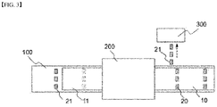
- FIG. 3 is a schematic diagram showing a method for manufacturing an electrode plate according to first embodiment of the present invention.
- the electrode current collector sheet 100 is moved from left to right, and the electrode current collector sheet 100 consecutively goes through a series of processes while moving from left to right.
- an adhesive film 21 is attached on the portion where the non-coated part is to be formed in the electrode current collector sheet 100 according to the manufacturing method of the present embodiment.
- the attachment of the adhesive film 21 is carried out before the application of the electrode slurry, and there is no particular limitation on the attachment method.
- the adhesive film 21 can be automatically positioned and attached by automatically positioning the adhesive film 21 at non-coated parts by a robot which stores information on the positions where non-coated parts are to be formed.
- non-coated parts 20 are formed in specific positions in a spot shape at intervals. This is accomplished by using a specific adhesive film and peeling method of the present invention.
- the electrode slurry is consecutively applied on the electrode current collector sheet 100 including the portions where the adhesive film has been attached.
- a rectangle represented by the dotted line of FIG. 3 shows an adhesive film on which the electrode slurry has been applied.
- an electrode slurry coating portion 11 is formed as the electrode slurry is consecutively applied by the designed width direction length on the electrode current collector sheet 100 except for the non-coating portion at two ends in the width direction of the electrode current collector sheet 100. Since the electrode slurry is consecutively applied regardless of whether the adhesive film 21 has been attached, the coater discharge does not need to be stopped as in the conventional art.
- the electrode current collector sheet 100 is heated in a drying device 200, the electrode slurry on the electrode current collector sheet 100 is dried.
- the adhesive force of the adhesive film 21 on the lower portion of the electrode slurry decreases. That is, in the present invention, the drying of the electrode slurry and the adhesive force reduction of the adhesive film 21 are performed simultaneously in the drying process in the drying device 200 .
- the adhesive force of the adhesive film 21 on the electrode current collector sheet 100, which passed through the drying device 200 decreased, the adhesive film comes to be in an easily detachable state.
- the surface of the electrode current collector sheet 100 is exposed by peeling off the adhesive film 21, and this portion becomes the non-coated part 20.
- the adhesive force of the adhesive film 21 of the present invention decreases while going through the heat-drying process.
- the adhesive force of the adhesive film 21 decreases by heat during the heat-drying process.
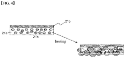
- FIG. 4 is a schematic diagram showing the structure of an adhesive film 21 used in the present invention.
- FIG. 4 shows an example of an adhesive film 21 in which the adhesive force decreases by heat in the heat-drying process.
- the adhesive film 21 includes an adhesive 21a, a filler 21b, and a film sheet 21c on which the adhesive 21a and the filler 21b are attached.
- the filler 21b expands. Then most of the adherend area with the surface of the electrode current collector sheet 100 is occupied by the filler 21b, which significantly reduces the adherend area of the sheet surface, and the adhesive film 21 comes to be in a removable state.
- the adhesive 21a can be manufactured using a known adhesive composition in the range of not interfering with the action of the filler 21b.
- acrylic adhesive which is obtained by mixing a flexible acrylate monomer and a hard acrylate monomer in a predetermined rate, may be used.
- a photoinitiator or a photocrosslinking agent can be added to the adhesive.
- a curable or thermoplastic product is preferably used as the filler 21b.
- a Polymeric Sphere Expancel 551 DU (product name) of AkzoNobel may be used.
- the composition of the filler 21b and the adhesive 21a, the diameter of the filler 21b, etc. can be appropriately selected in consideration of the adhesive force reduction at the time of later filler expansion.
- the diameter of the filler 21b is 6 to 24 microns.
- the filler 21b expands at a temperature of 80°C or higher.
- the filler 21b preferably expands in a general heat-drying temperature range of 100 to 200°C.
- the above-mentioned product filer 21b meets these conditions.
- the adhesive film peeling and retrieving mechanism of the present invention will be described with reference to FIG. 3 .
- the electrode slurry at the upper portion of the electrode current collector sheet 100 which has passed through the drying device 200, is dried and is coated on the surface of the electrode current collector sheet 100.
- the electrode slurry on the upper portion of the region where the adhesive film 21 has been attached is also dried, and the adhesive force of the adhesive film 21 at the lower portion decreases to thereby come to be in a peelable state.
- the adhesive film 21 should be removed using a predetermined peeling tool because it is not easily peeled off.
- the adhesive film can be retrieved by adsorbing the adhesive film 21 using a predetermined device.
- the adhesive film 21 can be peeled off by adsorbing the upper surface of the electrode current collector sheet 100 using a vacuum adsorption device 300.
- the adhesive force is much higher than that of the adhesive film 21, it cannot be peeled off by using the vacuum adsorption device 300.
- the adhesive film 21 can be retrieved by peeling off the adhesive film 21 using the vacuum adsorption device 300.
- the surface of the electrode current collector sheet 100 is exposed, and the exposed surface becomes the non-coated part 20.
- the pattern of the coated part, on which an electrode slurry has been coated, and the non-coated part without the electrode slurry is completed by the peeling and retrieving of the adhesive film.
- the process of peeling off the adhesive film 21 can be consecutively performed. Namely, for example, the adhesive film 21 can be peeled off by adsorbing the front surface of the electrode current collector sheet 100 while moving along the upper surface of the electrode current collector sheet 100 without needing to peel off the adhesive film 21 by making a peeling device approach the portion where the adhesive film 21 has been attached.
- the electrode slurry of the coated part 10 has been firmly attached on the surface of the electrode current collector sheet 100, the electrode slurry is not peeled off by adsorption by the vacuum adsorption device 300, and only the adhesive film 21 on the portion, where the non-coated part has been formed, can be easily peeled off by the decrease of the adhesive force.
- the adhesive film 21 can be peeled off while moving along the entire upper surface of the electrode current collector sheet 100 without needing to specifying the portions where the adhesive film has been attached, the peeling efficiency and productivity can be significantly improved.
- the electrode current collector sheet 100 is moved from left to right along the manufacturing line, a consecutive peeling is possible even when an adsorption device is fixed.
- the adsorption device can be moved at an appropriate speed in the opposite direction in consideration of the transfer speed of the electrode current collector sheet 100.
- FIG. 5 is a schematic diagram showing a method for manufacturing an electrode plate according to another embodiment of the present invention.
- the adhesive film attachment - electrode slurry application - heat-drying process is the same as in the first embodiment, and thus the description thereof is omitted here.
- the peeling and retrieving device of the adhesive film 21 is different from that in the first embodiment.
- the adhesive film 21 is peeled off by installing the adhesive roller 400 having an outer circumference on which an adhesive tape has been attached, at the electrode current collector sheet 100.
- the adhesive roller 400 peels off the adhesive film 21 on the surface of the electrode current collector sheet 100 while rotating counterclockwise.
- the peeling can be done with a simple device configuration, and a complicated vacuum adsorption device such as a vacuum pump as in the first embodiment is not necessary.
- the adhesive roller 400 since adsorption is performed by a vacuum adsorption device 300, it is possible not to contact the surface of the electrode current collector sheet 100 by adsorption at the upper portion at a little interval from the surface of the electrode current collector sheet 100. Since the adhesive roller 400 is peeled off by contacting the surface of the electrode current collector sheet 100, it may influence the surface of the electrode current collector sheet 100. On the other hand, it can be advantageous in terms of peeling force because it is directly contacted and peeled. In the present embodiment, it is possible to efficiently peel off the adhesive film 21 while moving along the entire upper surface of the electrode current collector sheet 100 (or it may be fixed if the electrode current collector sheet 100 is moved).
- the electrode slurry of the coated part 10 may be lifted on the boundary portion between the non-coated part 20 and the coated part 10 due to the peeling force.
- the electrode current collector sheet 100 after the heat-drying process is to go through a rolling process in which the surface of the electrode is pressed to be flat, and thus such a lifting is not a big problem.
- the surface of the electrode current collector sheet 100 is pressed by a roll press, the boundary portion between the coated part 10 and the non-coated part 20 may also become flat.
- FIG. 6 is a schematic diagram showing a method for manufacturing an electrode plate according to further another embodiment of the present invention.
- the number of adhesive films 21 has decreased from 3 to 2 along the width direction of the electrode current collector sheet 100.
- the pattern of the non-coated part 20 can be adjusted by adjusting the number of the adhesive films 21 and the attached locations of the adhesive films 21.
- the pattern of the non-coated part 20 and ultimately the pattern on the electrode current collector sheet 100 can be adjusted by adjusting the size and shape, etc. of the adhesive film 21.
- the present invention it is possible to make various patterns for manufacturing electrode cells by changing at least one of the number, location, size and shape of the adhesive films 21. Namely, since it is possible to make a pattern corresponding to the type and shape of the electrode tab, the degree of freedom for the pattern formation increases.
- the coating speed can be dramatically raised by a continuous pattern coating by the method of the present invention. Further, the automation rate of the manufacturing process can be raised by continuous peeling of the adhesive film 21 described above, and the productivity can be further increased.
- the electrode plate for the secondary battery prepared by the method of the present invention can improve the battery capacity and energy density.
- an electrode plate which is manufactured by the method of the present invention includes: at least one coated part 10, on which an electrode slurry has been coated, and at least one non-coated part 20, on which the electrode slurry has not been coated.
- the non-coated part 20 is positioned along a longitudinal direction of the electrode current collector sheet 100 at regular intervals, a plurality of non-coated parts 20 are formed to be spaced apart from each other along a width direction of the electrode current collector sheet 100, and the coated part 10 is formed on at least portion other than the non-coated part 20.
- non-coated parts are formed between coated parts in a band shape, and the electrode slurry is not applied on the band shape portion.
- the electrode slurry may be coated on a portion between non-coated parts 20. This is due to the unique configuration according to attachment and peeling of the adhesive film 21.
- the non-coated part 20 formed on the left and right side of the coated part 10 of FIG. 6 is removed by the slitting process. Therefore, in the electrode plate, the coated part 10, on which an electrode slurry has been coated, may be formed on the region other than the non-coated part 20.
- the coated portion of the electrode slurry when the coated portion of the electrode slurry is enlarged, the portion substantially contributing to the battery capacity is increased, so that the battery capacity can be improved.
- the energy density can also be improved.
- the electrode plate of FIG. 6 will be more advantageous than that of FIG. 3 and FIG. 5 .
- the coated part 10 is not that the enlargement of the coated part 10 is unconditionally possible, and the coated part 10 can be enlarged under a constraint that the surface of a sheet (metal), which is necessary for the structure of other battery assemblies, the number, location and shape of the tab portions.
- the pattern coating technology of the present invention can be applied to both the positive electrode and the negative electrode. Further, it can be appropriately applied according to the battery type, and particularly, a pattern electrode, which is necessary to manufacture a jelly roll electrode, can be obtained by a consecutive coating process.
Landscapes
- Engineering & Computer Science (AREA)
- Chemical & Material Sciences (AREA)
- Manufacturing & Machinery (AREA)
- Chemical Kinetics & Catalysis (AREA)
- Electrochemistry (AREA)
- General Chemical & Material Sciences (AREA)
- Materials Engineering (AREA)
- Battery Electrode And Active Subsutance (AREA)
Abstract
Description
- The present invention relates to a method for manufacturing an electrode plate for a secondary battery.
- The present invention also relates to an electrode plate for a secondary battery, which is manufactured by the method for manufacturing the electrode plate.
- This application claims the benefit of priority based on
Korean Patent Application No. 10-2020-0139040, filed on October 26, 2020 - With the increase in technology development and demand for mobile devices, the demand for secondary batteries is also rapidly increasing. Among them, lithium secondary batteries are widely used as an energy source for various electronic products as well as various mobile devices because of their high energy density and high operating voltage and excellent storage and lifetime characteristics.
- An electrode assembly for charging and discharging electric energy in a case is built in the lithium secondary battery. Electrodes (positive electrode and negative electrode) constituting the electrode assembly generate electric current through ion exchange, and each of the positive electrode and the negative electrode is manufactured as an electrode substrate, which is obtained by applying an electrode slurry on the surface of a current collector made of an aluminum or copper film and drying the electrode slurry, is tab-processed and is cut in an appropriate size. The electrode slurry is applied on the surface of the current collector in a form in which a solvent is mixed with an active material, and is manufactured as an electrode substrate. The electrode substrate is dried to allow the electrode active material to be hardened on the surface of the current collector by evaporating the solvent of the electrode slurry.
-
FIG. 1 is a schematic diagram of a heat drying device for drying an electrode substrate. - As illustrated in
FIG. 1 , during the process that thecurrent collector sheet 2a is unwound from an unwinding roller 1a and is then wound on awinding roller 1b, anelectrode substrate 2, which is obtained as an electrode slurry has been applied on the surface of thecurrent collector sheet 2a through acoater 7, is made to pass through anelectrode oven 4 by a roller 6 to be heat-dried, which is then wound on thewinding roller 1b. Theelectrode oven 4 has one ormore drying chambers heater 5. -
FIG. 2 illustrates a sequential pattern of an electrode current collector sheet. - The portion where the electrode slurry has been coated (coated part 10) and the portion where the electrode slurry has not been coated (non-coated part 20) are alternatively arranged on the
current collector sheet 100. - The
non-coated part 20 is formed because the surface of the exposed electrode current collector sheet (metal) is necessary to form a terminal for connecting a positive electrode to a negative electrode at the time of later forming an electrode assembly. A tab may be formed on the non-coatedpart 20 through a later notch process, etc. - In a conventional art, in order to form such an electrode pattern, an intermittent or discontinuous coating job, in which the start and stop of the electrode slurry discharge are repeated while moving the coater or the current collector according to the pattern of the coated
part 10 or the non-coatedpart 20, was performed. When the coating speed is relatively slow, the pattern can be accurately formed to some extent by such a discontinuous coating job, but the productivity may decrease because the working speed is significantly slow. - Further, when the coating speed increases, it is difficult to syntonize the mechanical control of the coater head to the coating speed, thereby making it difficult to form a pattern where the non-coated part and the coated part are alternately repeated.
- Further, in the conventional electrode plate, non-coated
parts 20 formed between the coatedparts 10 are formed in the width direction of the electrode plate as shown inFIG. 2 . Since the electrode slurry is not applied on thenon-coated part 20, it does not contribute to the increase in battery capacity or energy density. - Therefore, there is a need for a technology for improving the battery capacity, etc. while improving the coating speed of the electrode pattern.
-
Korea Patent Publication No. 10-2015-0049516 - The present invention is believed to solve at least some of the above problems. For example, an aspect of the present invention provides a method for manufacturing an electrode plate for a secondary battery, which can improve the coating speed by consecutively coating an electrode slurry on an electrode current collector sheet.
- Further, another aspect of the present invention provides a method for manufacturing an electrode plate for a secondary battery, which can efficiently form an electrode pattern on an electrode by simply peeling off a non-coated part on an electrode current collector.
- Further, another aspect of the present invention provides a method for manufacturing an electrode plate for a secondary battery, which can increase the battery capacity and energy density by enlarging the electrode-slurry-coated part.
- Further, the present invention relates to an electrode plate for a secondary battery, which is manufactured by the above manufacturing method and can increase the battery capacity and energy density.
- A method for manufacturing an electrode plate for a secondary battery of the present invention for solving the above problems is a method for manufacturing an electrode plate by performing a pattern-coating to have a coated part, on which an electrode slurry has been coated, and a non-coated part, on which the electrode slurry has not been coated, on an electrode current collector sheet, including: attaching at least one adhesive films on at least one portion of the non-coated part on the electrode current collector sheet; consecutively coating an electrode slurry on the electrode current collector sheet including the adhesive-film-attached parts; heating and drying the electrode slurry; and peeling the adhesive film from the electrode current collector sheet and retrieving the adhesive film. Herein, an adhesive force of the adhesive film is reduced by the heating and drying of the electrode slurry, so that the adhesive film can be removed from the electrode current collector sheet during the peeling and retrieving, and as the adhesive film is removed, a surface of the electrode current collector sheet is exposed.
- Specifically, the adhesive force of the adhesive film is reduced by heat during the heating and drying of the electrode slurry.
- In one example, the adhesive film includes a filler which expands in volume by heat.
- The filler may expand in a temperature of 80°C or higher, and preferably in a temperature between 100 and 200°C.
- The adhesive film may be peeled off from the surface of the electrode current collector sheet by adsorbing the adhesive film.
- In an example of the present invention, the adhesive film may be peeled off by vacuum-adsorbing the adhesive film by using a vacuum adsorption device.
- In another example of the present invention, the adhesive film may be peeled off by adsorbing the adhesive film onto an adhesive roller having an outer circumference on which an adhesive tape has been attached.
- Preferably, the adhesive film may be peeled off by adsorbing the electrode current collector sheet while moving along an upper surface of the electrode current collector sheet.
- The surface of the electrode current collector sheet may be pressed to be flat after removing the adhesive film.
- Further, the pattern on the electrode current collector sheet may be adjusted by adjusting at least one of the number, the size and the shape of the adhesive film, and the location where the adhesive film is attached.
- Further, in another aspect of the present invention, an electrode plate for a secondary battery may be provided by the above method. In one example, the electrode plate comprising an electrode current collector sheet including at least one coated part, on which an electrode slurry has been coated, and at least one non-coated part, on which the electrode slurry has not been coated, on an electrode current collector sheet. Herein, the non-coated part is positioned along a longitudinal direction of the electrode current collector sheet at regular intervals, the non-coated part is formed to be spaced apart from each other along a width direction of the electrode current collector sheet, and the coated part is formed on at least portion other than the non-coated part.
- According to the present invention, it is possible to significantly improve the coating speed of the electrode slurry by consecutively forming an electrode pattern.
- Further, according to the present invention, it is possible to increase the battery capacity and energy density by enlarging the electrode-slurry-coated part by forming the non-coated part at only desired places on the electrode current collector.
- Further, according to the present invention, the adhesive film for forming a non-coated part pattern on the electrode current collector can be consecutively peeled off while moving along the surface of the electrode current collector sheet, which is an advantage.
-
-
FIG. 1 is a schematic diagram of a heat drying device for drying an electrode substrate. -
FIG. 2 is a schematic diagram showing a discontinuous pattern forming method on a conventional electrode current collector sheet. -
FIG. 3 is a schematic diagram showing a method for manufacturing an electrode plate according to an embodiment of the present invention. -
FIG. 4 is a schematic diagram showing the structure of an adhesive film used in the present invention. -
FIG. 5 is a schematic diagram showing a method for manufacturing an electrode plate according to another embodiment of the present invention. -
FIG. 6 is a schematic diagram showing a method for manufacturing an electrode plate according to further another embodiment of the present invention. - Hereinafter, the detailed configuration of the present invention will be described in detail with reference to the accompanying drawings and various embodiments. Embodiments described below are exemplary to assist in understanding of the present invention, and in order to help understand the invention, the accompanying drawings are not shown as actual scale and the dimensions of some components may be exaggerated.
- As the inventive concept allows for various changes and numerous embodiments, particular embodiments will be illustrated in the drawings and described in detail in the text. However, this is not intended to limit the present invention to the specific form disclosed, and it should be understood to include all changes, equivalents, and substitutes included in the spirit and scope of the present invention.
- The present invention is devised to improve a conventional a discontinuous pattern coating technology (see
FIG. 2 ) which forms a coated part, on which an electrode slurry discharged from a coater is applied in the process of moving the electrode current collector sheet, and forms a non-coated part without an electrode slurry by stopping the discharge of the electrode slurry. - A main feature of the present invention is in attaching an adhesive film on a portion where a non-coated part is to be formed in order to consecutively perform a discontinuous pattern coating.
- Further, an electrode slurry is consecutively coated on the electrode current collector sheet including the adhesive-film-attached portion. Hence, an electrode slurry is applied on the upper portion of the adhesive film. What is important is whether it is possible to efficiently peel off and retrieve the adhesive film, on which an electrode slurry has been applied. When the peeling and retrieving process of the adhesive film becomes difficult, it is not possible to appropriately form a non-coated part. As such, the technical significance of the converting the discontinuous coating into a continuous coating significantly decreases. The present invention adopts a means which makes the peeling of the adhesive film easy by naturally reducing the adhesive force of the adhesive film through a heat-drying process of the electrode slurry. Namely, the adhesive force of the adhesive film is not reduced by a separate heating or cooling process after the heat-drying process of the electrode slurry, but the adhesive force of the adhesive film can be reduced by high temperature heat applied during the heat-drying process of the electrode slurry. Hence, according to the present invention, a series of process flows of the consecutive coating process-heat-drying process of
FIG. 1 are not interfered. Accordingly, the method of the present invention is more suitable for automation of equipment and further improves the productivity. - The present invention uses a specific adhesive film that reduces adhesive force by heat by heat for this purpose.
-
FIG. 3 is a schematic diagram showing a method for manufacturing an electrode plate according to first embodiment of the present invention. - In
FIG. 3 , the electrodecurrent collector sheet 100 is moved from left to right, and the electrodecurrent collector sheet 100 consecutively goes through a series of processes while moving from left to right. - First, an
adhesive film 21 is attached on the portion where the non-coated part is to be formed in the electrodecurrent collector sheet 100 according to the manufacturing method of the present embodiment. The attachment of theadhesive film 21 is carried out before the application of the electrode slurry, and there is no particular limitation on the attachment method. Preferably, theadhesive film 21 can be automatically positioned and attached by automatically positioning theadhesive film 21 at non-coated parts by a robot which stores information on the positions where non-coated parts are to be formed. Unlike conventional non-coated parts formed in a band shape between thecoated parts 10, in the present invention,non-coated parts 20 are formed in specific positions in a spot shape at intervals. This is accomplished by using a specific adhesive film and peeling method of the present invention. - After attaching the
adhesive film 21, the electrode slurry is consecutively applied on the electrodecurrent collector sheet 100 including the portions where the adhesive film has been attached. A rectangle represented by the dotted line ofFIG. 3 shows an adhesive film on which the electrode slurry has been applied. As such, an electrodeslurry coating portion 11 is formed as the electrode slurry is consecutively applied by the designed width direction length on the electrodecurrent collector sheet 100 except for the non-coating portion at two ends in the width direction of the electrodecurrent collector sheet 100. Since the electrode slurry is consecutively applied regardless of whether theadhesive film 21 has been attached, the coater discharge does not need to be stopped as in the conventional art. - Thereafter, as the electrode
current collector sheet 100 is heated in adrying device 200, the electrode slurry on the electrodecurrent collector sheet 100 is dried. In this heat-drying process, the adhesive force of theadhesive film 21 on the lower portion of the electrode slurry decreases. That is, in the present invention, the drying of the electrode slurry and the adhesive force reduction of theadhesive film 21 are performed simultaneously in the drying process in thedrying device 200 . Hence, since the adhesive force of theadhesive film 21 on the electrodecurrent collector sheet 100, which passed through thedrying device 200, decreased, the adhesive film comes to be in an easily detachable state. The surface of the electrodecurrent collector sheet 100 is exposed by peeling off theadhesive film 21, and this portion becomes thenon-coated part 20. - The adhesive force of the
adhesive film 21 of the present invention decreases while going through the heat-drying process. In the present embodiment, the adhesive force of theadhesive film 21 decreases by heat during the heat-drying process. -
FIG. 4 is a schematic diagram showing the structure of anadhesive film 21 used in the present invention.FIG. 4 shows an example of anadhesive film 21 in which the adhesive force decreases by heat in the heat-drying process. As illustrated, theadhesive film 21 includes an adhesive 21a, afiller 21b, and a film sheet 21c on which the adhesive 21a and thefiller 21b are attached. When heat is applied, thefiller 21b expands. Then most of the adherend area with the surface of the electrodecurrent collector sheet 100 is occupied by thefiller 21b, which significantly reduces the adherend area of the sheet surface, and theadhesive film 21 comes to be in a removable state. - The adhesive 21a can be manufactured using a known adhesive composition in the range of not interfering with the action of the
filler 21b. For example, acrylic adhesive, which is obtained by mixing a flexible acrylate monomer and a hard acrylate monomer in a predetermined rate, may be used. If necessary, a photoinitiator or a photocrosslinking agent can be added to the adhesive. A curable or thermoplastic product is preferably used as thefiller 21b. For example, a Polymeric Sphere Expancel 551 DU (product name) of AkzoNobel may be used. The composition of thefiller 21b and the adhesive 21a, the diameter of thefiller 21b, etc. can be appropriately selected in consideration of the adhesive force reduction at the time of later filler expansion. Preferably, the diameter of thefiller 21b is 6 to 24 microns. - One having a characteristic of expanding during the heat-drying process of the electrode slurry may be used as the
filler 21b. Hence, thefiller 21b expands at a temperature of 80°C or higher. Thefiller 21b preferably expands in a general heat-drying temperature range of 100 to 200°C. The above-mentionedproduct filer 21b meets these conditions. - The adhesive film peeling and retrieving mechanism of the present invention will be described with reference to
FIG. 3 . - The electrode slurry at the upper portion of the electrode
current collector sheet 100, which has passed through thedrying device 200, is dried and is coated on the surface of the electrodecurrent collector sheet 100. The electrode slurry on the upper portion of the region where theadhesive film 21 has been attached is also dried, and the adhesive force of theadhesive film 21 at the lower portion decreases to thereby come to be in a peelable state. However, since the electrode slurry on the upper portion of theadhesive film 21 is connected to the electrode slurry on the portion (coated part) without including theadhesive film 21, theadhesive film 21 should be removed using a predetermined peeling tool because it is not easily peeled off. The adhesive film can be retrieved by adsorbing theadhesive film 21 using a predetermined device. - Namely, as shown in
FIG. 3 , theadhesive film 21 can be peeled off by adsorbing the upper surface of the electrodecurrent collector sheet 100 using avacuum adsorption device 300. At this time, since the electrode slurry portion, on which theadhesive film 21 has not been attached, has been coated on the surface of the electrodecurrent collector sheet 100, the adhesive force is much higher than that of theadhesive film 21, it cannot be peeled off by using thevacuum adsorption device 300. Hence, theadhesive film 21 can be retrieved by peeling off theadhesive film 21 using thevacuum adsorption device 300. Whenadhesive film 21 is retrieved, the surface of the electrodecurrent collector sheet 100 is exposed, and the exposed surface becomes thenon-coated part 20. Hence, the pattern of the coated part, on which an electrode slurry has been coated, and the non-coated part without the electrode slurry is completed by the peeling and retrieving of the adhesive film. - In the present invention, the process of peeling off the
adhesive film 21 can be consecutively performed. Namely, for example, theadhesive film 21 can be peeled off by adsorbing the front surface of the electrodecurrent collector sheet 100 while moving along the upper surface of the electrodecurrent collector sheet 100 without needing to peel off theadhesive film 21 by making a peeling device approach the portion where theadhesive film 21 has been attached. As described, since the electrode slurry of thecoated part 10 has been firmly attached on the surface of the electrodecurrent collector sheet 100, the electrode slurry is not peeled off by adsorption by thevacuum adsorption device 300, and only theadhesive film 21 on the portion, where the non-coated part has been formed, can be easily peeled off by the decrease of the adhesive force. Hence, since theadhesive film 21 can be peeled off while moving along the entire upper surface of the electrodecurrent collector sheet 100 without needing to specifying the portions where the adhesive film has been attached, the peeling efficiency and productivity can be significantly improved. Herein, since the electrodecurrent collector sheet 100 is moved from left to right along the manufacturing line, a consecutive peeling is possible even when an adsorption device is fixed. Alternatively, the adsorption device can be moved at an appropriate speed in the opposite direction in consideration of the transfer speed of the electrodecurrent collector sheet 100. -
FIG. 5 is a schematic diagram showing a method for manufacturing an electrode plate according to another embodiment of the present invention. - The adhesive film attachment - electrode slurry application - heat-drying process is the same as in the first embodiment, and thus the description thereof is omitted here. In the present embodiment, the peeling and retrieving device of the
adhesive film 21 is different from that in the first embodiment. In the present embodiment, theadhesive film 21 is peeled off by installing theadhesive roller 400 having an outer circumference on which an adhesive tape has been attached, at the electrodecurrent collector sheet 100. - When the electrode
current collector sheet 100 is moved from left to right, theadhesive roller 400 peels off theadhesive film 21 on the surface of the electrodecurrent collector sheet 100 while rotating counterclockwise. In the present embodiment, the peeling can be done with a simple device configuration, and a complicated vacuum adsorption device such as a vacuum pump as in the first embodiment is not necessary. - Further, in the first embodiment, since adsorption is performed by a
vacuum adsorption device 300, it is possible not to contact the surface of the electrodecurrent collector sheet 100 by adsorption at the upper portion at a little interval from the surface of the electrodecurrent collector sheet 100. Since theadhesive roller 400 is peeled off by contacting the surface of the electrodecurrent collector sheet 100, it may influence the surface of the electrodecurrent collector sheet 100. On the other hand, it can be advantageous in terms of peeling force because it is directly contacted and peeled. In the present embodiment, it is possible to efficiently peel off theadhesive film 21 while moving along the entire upper surface of the electrode current collector sheet 100 (or it may be fixed if the electrodecurrent collector sheet 100 is moved). - When contacting along the surface of the electrode current collector sheet (coated part 10) according to the second embodiment, or in the case of the first embodiment, the electrode slurry of the
coated part 10 may be lifted on the boundary portion between thenon-coated part 20 and thecoated part 10 due to the peeling force. - However, the electrode
current collector sheet 100 after the heat-drying process is to go through a rolling process in which the surface of the electrode is pressed to be flat, and thus such a lifting is not a big problem. For example, if the surface of the electrodecurrent collector sheet 100 is pressed by a roll press, the boundary portion between thecoated part 10 and thenon-coated part 20 may also become flat. -
FIG. 6 is a schematic diagram showing a method for manufacturing an electrode plate according to further another embodiment of the present invention. - In the present embodiment, the number of
adhesive films 21 has decreased from 3 to 2 along the width direction of the electrodecurrent collector sheet 100. - Likewise, in the present invention, the pattern of the
non-coated part 20 can be adjusted by adjusting the number of theadhesive films 21 and the attached locations of theadhesive films 21. Alternatively, the pattern of thenon-coated part 20 and ultimately the pattern on the electrodecurrent collector sheet 100 can be adjusted by adjusting the size and shape, etc. of theadhesive film 21. - Hence, according to the present invention, it is possible to make various patterns for manufacturing electrode cells by changing at least one of the number, location, size and shape of the
adhesive films 21. Namely, since it is possible to make a pattern corresponding to the type and shape of the electrode tab, the degree of freedom for the pattern formation increases. - The coating speed can be dramatically raised by a continuous pattern coating by the method of the present invention. Further, the automation rate of the manufacturing process can be raised by continuous peeling of the
adhesive film 21 described above, and the productivity can be further increased. - Further, the electrode plate for the secondary battery prepared by the method of the present invention can improve the battery capacity and energy density.
- Referring to
FIGS. 3 ,5 and6 , an electrode plate, which is manufactured by the method of the present invention includes: at least onecoated part 10, on which an electrode slurry has been coated, and at least onenon-coated part 20, on which the electrode slurry has not been coated. Herein, thenon-coated part 20 is positioned along a longitudinal direction of the electrodecurrent collector sheet 100 at regular intervals, a plurality ofnon-coated parts 20 are formed to be spaced apart from each other along a width direction of the electrodecurrent collector sheet 100, and thecoated part 10 is formed on at least portion other than thenon-coated part 20. Namely, in a conventional electrode plate for a secondary battery, non-coated parts are formed between coated parts in a band shape, and the electrode slurry is not applied on the band shape portion. However, in the present invention, the electrode slurry may be coated on a portion betweennon-coated parts 20. This is due to the unique configuration according to attachment and peeling of theadhesive film 21. Thenon-coated part 20 formed on the left and right side of thecoated part 10 ofFIG. 6 is removed by the slitting process. Therefore, in the electrode plate, thecoated part 10, on which an electrode slurry has been coated, may be formed on the region other than thenon-coated part 20. - As such, when the coated portion of the electrode slurry is enlarged, the portion substantially contributing to the battery capacity is increased, so that the battery capacity can be improved. In addition, since more electrode slurry is applied on the electrode
current collector sheet 100 of the same area, the energy density can also be improved. In terms of capacity and energy density improvement, the electrode plate ofFIG. 6 will be more advantageous than that ofFIG. 3 andFIG. 5 . - However, it should be noted that it is not that the enlargement of the
coated part 10 is unconditionally possible, and thecoated part 10 can be enlarged under a constraint that the surface of a sheet (metal), which is necessary for the structure of other battery assemblies, the number, location and shape of the tab portions. - The pattern coating technology of the present invention can be applied to both the positive electrode and the negative electrode. Further, it can be appropriately applied according to the battery type, and particularly, a pattern electrode, which is necessary to manufacture a jelly roll electrode, can be obtained by a consecutive coating process.
- In the above, the present invention has been described in more detail through the drawings and examples. Accordingly, the embodiments described in the specification and the configurations described in the drawings are only the most preferred embodiments of the present invention, and do not represent all of the technical ideas of the present invention. It is to be understood that there may be various equivalents and variations in place of them at the time of filing the present application.
-
- 10: coated part
- 11: electrode slurry coating portion
- 20: non-coated part
- 21: adhesive film
- 21a: adhesive
- 21b: filler
- 21c: film sheet
- 100: electrode current collector sheet
- 200: drying device
- 300: vacuum adsorption device
- 400: adhesive roller
Claims (12)
- A method for manufacturing an electrode plate by performing a pattern-coating to have a coated part, on which an electrode slurry has been coated, and a non-coated part, on which the electrode slurry has not been coated, on an electrode current collector sheet, the method comprising:attaching at least one adhesive films on at least one portion of the non-coated part on the electrode current collector sheet;consecutively coating an electrode slurry on the electrode current collector sheet including the adhesive-film-attached parts;heating and drying the electrode slurry; andpeeling the adhesive film from the electrode current collector sheet and retrieving the adhesive film,wherein an adhesive force of the adhesive film is reduced by the heating and drying of the electrode slurry, so that the adhesive film can be removed from the electrode current collector sheet during the peeling and retrieving, and as the adhesive film is removed, a surface of the electrode current collector sheet is exposed.
- The method of claim 1, wherein the adhesive force of the adhesive film is reduced by heat during the heating and drying of the electrode slurry.
- The method of claim 1, wherein the adhesive film includes a filler which expands in volume by heat.
- The method of claim 3, wherein the filler expands in a temperature of 80°C or higher.
- The method of claim 4, wherein the filler expands in a temperature between 100 and 200°C.
- The method of claim 1, wherein the adhesive film is peeled off from the surface of the electrode current collector sheet by adsorbing the adhesive film.
- The method of claim 6, wherein the adhesive film is peeled off by vacuum-adsorbing the adhesive film by using a vacuum adsorption device.
- The method of claim 6, wherein the adhesive film is peeled off by adsorbing the adhesive film onto an adhesive roller having an outer circumference on which an adhesive tape has been attached.
- The method of claim 6, wherein the adhesive film is peeled off by adsorbing the electrode current collector sheet while moving along an upper surface of the electrode current collector sheet.
- The method of claim 1, wherein a surface of the electrode current collector sheet is pressed to be flat after removing the adhesive film.
- The method of claim 1, wherein the pattern on the electrode current collector sheet is adjusted by adjusting at least one of a number, a size and a shape of the adhesive film, and a position where the adhesive film is attached.
- An electrode plate for a secondary battery, the electrode plate comprising an electrode current collector sheet including at least one coated part, on which an electrode slurry has been coated, and at least one non-coated part, on which the electrode slurry has not been coated, on an electrode current collector sheet,
wherein the non-coated part is positioned along a longitudinal direction of the electrode current collector sheet at regular intervals, a plurality of non-coated parts are formed to be spaced apart from each other along a width direction of the electrode current collector sheet, and the coated part is formed on portion other than the non-coated part.
Applications Claiming Priority (2)
| Application Number | Priority Date | Filing Date | Title |
|---|---|---|---|
| KR1020200139040A KR102940100B1 (en) | 2020-10-26 | 2020-10-26 | Manufacturing method for electorde plate for secondary battery and electorde plate for secondary battery |
| PCT/KR2021/012867 WO2022092577A1 (en) | 2020-10-26 | 2021-09-17 | Method for manufacturing electrode plate for secondary battery, and electrode plate for secondary battery |
Publications (3)
| Publication Number | Publication Date |
|---|---|
| EP4099423A1 true EP4099423A1 (en) | 2022-12-07 |
| EP4099423A4 EP4099423A4 (en) | 2024-08-28 |
| EP4099423B1 EP4099423B1 (en) | 2025-10-29 |
Family
ID=81384199
Family Applications (1)
| Application Number | Title | Priority Date | Filing Date |
|---|---|---|---|
| EP21886571.5A Active EP4099423B1 (en) | 2020-10-26 | 2021-09-17 | Method for manufacturing electrode plate for secondary battery |
Country Status (6)
| Country | Link |
|---|---|
| US (1) | US12609291B2 (en) |
| EP (1) | EP4099423B1 (en) |
| KR (1) | KR102940100B1 (en) |
| CN (1) | CN115280544B (en) |
| ES (1) | ES3055532T3 (en) |
| WO (1) | WO2022092577A1 (en) |
Families Citing this family (2)
| Publication number | Priority date | Publication date | Assignee | Title |
|---|---|---|---|---|
| WO2025225990A1 (en) * | 2024-04-22 | 2025-10-30 | 주식회사 엘지에너지솔루션 | Method for manufacturing electrode and electrode |
| KR20260041481A (en) * | 2024-09-20 | 2026-03-27 | 삼성에스디아이 주식회사 | Manufacturing device of all-solid-state battery and manufacturing method of all-solid-state battery using the same |
Family Cites Families (17)
| Publication number | Priority date | Publication date | Assignee | Title |
|---|---|---|---|---|
| JPH10144301A (en) * | 1996-11-06 | 1998-05-29 | Dainippon Printing Co Ltd | Electrode plate for non-aqueous electrolyte secondary battery and method for producing the same |
| KR19990028142A (en) * | 1997-09-30 | 1999-04-15 | 왕중일 | Manufacturing method of battery pole plate |
| JP4643780B2 (en) | 1998-11-12 | 2011-03-02 | 大日本印刷株式会社 | Non-aqueous electrolyte secondary battery electrode plate and method for producing the same |
| CA2881826C (en) * | 2012-08-17 | 2021-03-30 | Visual Physics, Llc | A process for transferring microstructures to a final substrate |
| KR101428541B1 (en) | 2012-09-11 | 2014-08-12 | 주식회사 루트제이드 | Wrapping electrode plate for use in lithium ion secondary battery and manufacturing method of the same |
| DE102013106353B4 (en) | 2013-06-18 | 2018-06-28 | Tdk Corporation | Method for applying a structured coating to a component |
| KR101651516B1 (en) | 2013-10-30 | 2016-08-26 | 주식회사 엘지화학 | A Cell Assembly with Improved Jelly-Roll Type Structure and A Secondary Battery Comprising the Same |
| KR101875892B1 (en) * | 2016-03-10 | 2018-07-06 | 씨아이에스(주) | Slurry coating methode for secondary cell and secondary cell manufactured using the same |
| KR101991934B1 (en) * | 2016-07-15 | 2019-06-24 | 주식회사 엘지화학 | Electrode and manufacturing method for the electrode |
| JP6766580B2 (en) | 2016-10-13 | 2020-10-14 | 大日本印刷株式会社 | Electrode plate with film |
| KR102241465B1 (en) | 2017-11-30 | 2021-04-16 | 주식회사 엘지화학 | Multiple layer electrode and preparing method of the same |
| US20200266418A1 (en) * | 2018-03-23 | 2020-08-20 | EnPower, Inc. | Gap section multilayer electrode profile |
| KR102346181B1 (en) | 2018-04-13 | 2022-01-03 | (주)풍산디에이케이 | Manufacturing method and partial plating system for electrode terminal for secondary battery |
| KR102417105B1 (en) | 2018-06-20 | 2022-07-04 | 주식회사 엘지에너지솔루션 | Electrode assembly with improved connection between current collector and electrode tap and method of manufacturing the same |
| KR20200119728A (en) | 2019-04-10 | 2020-10-20 | 에스케이이노베이션 주식회사 | Lithium secondary battery comprising negative electrode improved in protection against degradation, and method of manufacturing the same |
| EP3955340A4 (en) * | 2019-04-10 | 2023-01-04 | SK Innovation Co., Ltd. | SECONDARY LITHIUM BATTERY COMPRISING A NEGATIVE ELECTRODE HAVING IMPROVED RESISTANCE TO DEGRADATION, AND METHOD OF MANUFACTURING THEREOF |
| KR102693232B1 (en) | 2019-06-03 | 2024-08-09 | 에스케이하이닉스 주식회사 | Semiconductor memory device and method for operating thereof |
-
2020
- 2020-10-26 KR KR1020200139040A patent/KR102940100B1/en active Active
-
2021
- 2021-09-17 EP EP21886571.5A patent/EP4099423B1/en active Active
- 2021-09-17 CN CN202180019964.9A patent/CN115280544B/en active Active
- 2021-09-17 WO PCT/KR2021/012867 patent/WO2022092577A1/en not_active Ceased
- 2021-09-17 ES ES21886571T patent/ES3055532T3/en active Active
- 2021-09-17 US US17/909,094 patent/US12609291B2/en active Active
Also Published As
| Publication number | Publication date |
|---|---|
| ES3055532T3 (en) | 2026-02-12 |
| CN115280544A (en) | 2022-11-01 |
| CN115280544B (en) | 2026-02-03 |
| US20230378418A1 (en) | 2023-11-23 |
| EP4099423B1 (en) | 2025-10-29 |
| KR20220054995A (en) | 2022-05-03 |
| WO2022092577A1 (en) | 2022-05-05 |
| KR102940100B1 (en) | 2026-03-16 |
| US12609291B2 (en) | 2026-04-21 |
| EP4099423A4 (en) | 2024-08-28 |
Similar Documents
| Publication | Publication Date | Title |
|---|---|---|
| CN111668451B (en) | A method for preparing pole pieces for wound multi-pole batteries, pole pieces and batteries | |
| US12609291B2 (en) | Method for manufacturing electrode plate for secondary battery, and electrode plate for secondary battery | |
| CN106159206B (en) | Preparation method of lithium ion battery pole piece | |
| KR101876402B1 (en) | manufacturing method of electrode plate for secondary battery and manufacturing device using its manufacturing method | |
| JP2005183181A (en) | Non-aqueous electrolyte secondary battery electrode plate and method for producing the same | |
| JP5541509B2 (en) | Method for manufacturing current collector electrode plate | |
| JP2005190787A (en) | Non-aqueous electrolyte secondary battery electrode plate and method for producing the same | |
| CN116826025B (en) | Lithium complex and preparation method thereof | |
| CN221694120U (en) | Coating device and pole piece production system | |
| CN112670437A (en) | Preparation method of battery pole piece | |
| JPH10214616A (en) | Method of manufacturing electrode for stacked battery | |
| KR102116676B1 (en) | Method for Preparing Electrode for Secondary Battery and Device for Manufacturing the Same | |
| KR20200102242A (en) | Substrate for electrode and method for manufacturing electrode using the same | |
| JP2005216723A (en) | Non-aqueous electrolyte secondary battery electrode plate and method for producing the same | |
| JP2005216722A (en) | Non-aqueous electrolyte secondary battery electrode plate and method for producing the same | |
| WO2019183615A1 (en) | Gap section multilayer electrode profile | |
| EP4571861A1 (en) | Method and apparatus for manufacturing an electrode foil | |
| JPH08250110A (en) | Method for manufacturing electrode plate for non-aqueous electrolyte secondary battery | |
| JPH11185734A (en) | Electrode plate for non-aqueous electrolyte secondary battery and method for producing the same | |
| WO2006114939A1 (en) | Electrode mixture paste coating method and coater | |
| CN112133877B (en) | Pole piece, winding type battery and coating method of pole piece | |
| CN116799132A (en) | Pole piece manufacturing method, pole piece and secondary battery | |
| CN116454214A (en) | System, method and product for pre-lithiating lithium ion battery electrodes using molten lithium | |
| JP2002361152A (en) | Double-side coater and manufacturing method of electrode for battery | |
| JP2002313328A (en) | Masking device and manufacturing method of electrode for use in nonaqueous electrolytic battery |
Legal Events
| Date | Code | Title | Description |
|---|---|---|---|
| STAA | Information on the status of an ep patent application or granted ep patent |
Free format text: STATUS: THE INTERNATIONAL PUBLICATION HAS BEEN MADE |
|
| PUAI | Public reference made under article 153(3) epc to a published international application that has entered the european phase |
Free format text: ORIGINAL CODE: 0009012 |
|
| STAA | Information on the status of an ep patent application or granted ep patent |
Free format text: STATUS: REQUEST FOR EXAMINATION WAS MADE |
|
| 17P | Request for examination filed |
Effective date: 20220829 |
|
| AK | Designated contracting states |
Kind code of ref document: A1 Designated state(s): AL AT BE BG CH CY CZ DE DK EE ES FI FR GB GR HR HU IE IS IT LI LT LU LV MC MK MT NL NO PL PT RO RS SE SI SK SM TR |
|
| DAV | Request for validation of the european patent (deleted) | ||
| DAX | Request for extension of the european patent (deleted) | ||
| A4 | Supplementary search report drawn up and despatched |
Effective date: 20240730 |
|
| RIC1 | Information provided on ipc code assigned before grant |
Ipc: H01M 4/139 20100101ALI20240724BHEP Ipc: H01M 4/04 20060101AFI20240724BHEP |
|
| GRAP | Despatch of communication of intention to grant a patent |
Free format text: ORIGINAL CODE: EPIDOSNIGR1 |
|
| STAA | Information on the status of an ep patent application or granted ep patent |
Free format text: STATUS: GRANT OF PATENT IS INTENDED |
|
| INTG | Intention to grant announced |
Effective date: 20250331 |
|
| P01 | Opt-out of the competence of the unified patent court (upc) registered |
Free format text: CASE NUMBER: APP_16847/2025 Effective date: 20250407 |
|
| GRAS | Grant fee paid |
Free format text: ORIGINAL CODE: EPIDOSNIGR3 |
|
| GRAA | (expected) grant |
Free format text: ORIGINAL CODE: 0009210 |
|
| STAA | Information on the status of an ep patent application or granted ep patent |
Free format text: STATUS: THE PATENT HAS BEEN GRANTED |
|
| AK | Designated contracting states |
Kind code of ref document: B1 Designated state(s): AL AT BE BG CH CY CZ DE DK EE ES FI FR GB GR HR HU IE IS IT LI LT LU LV MC MK MT NL NO PL PT RO RS SE SI SK SM TR |
|
| REG | Reference to a national code |
Ref country code: CH Ref legal event code: F10 Free format text: ST27 STATUS EVENT CODE: U-0-0-F10-F00 (AS PROVIDED BY THE NATIONAL OFFICE) Effective date: 20251029 Ref country code: GB Ref legal event code: FG4D |
|
| REG | Reference to a national code |
Ref country code: IE Ref legal event code: FG4D |
|
| REG | Reference to a national code |
Ref country code: DE Ref legal event code: R096 Ref document number: 602021041536 Country of ref document: DE |
|
| REG | Reference to a national code |
Ref country code: ES Ref legal event code: FG2A Ref document number: 3055532 Country of ref document: ES Kind code of ref document: T3 Effective date: 20260212 |
|
| REG | Reference to a national code |
Ref country code: NL Ref legal event code: MP Effective date: 20251029 |
|
| REG | Reference to a national code |
Ref country code: LT Ref legal event code: MG9D |
|
| PG25 | Lapsed in a contracting state [announced via postgrant information from national office to epo] |
Ref country code: NO Free format text: LAPSE BECAUSE OF FAILURE TO SUBMIT A TRANSLATION OF THE DESCRIPTION OR TO PAY THE FEE WITHIN THE PRESCRIBED TIME-LIMIT Effective date: 20260129 |
|
| PG25 | Lapsed in a contracting state [announced via postgrant information from national office to epo] |
Ref country code: HR Free format text: LAPSE BECAUSE OF FAILURE TO SUBMIT A TRANSLATION OF THE DESCRIPTION OR TO PAY THE FEE WITHIN THE PRESCRIBED TIME-LIMIT Effective date: 20251029 Ref country code: AT Free format text: LAPSE BECAUSE OF FAILURE TO SUBMIT A TRANSLATION OF THE DESCRIPTION OR TO PAY THE FEE WITHIN THE PRESCRIBED TIME-LIMIT Effective date: 20251029 Ref country code: FI Free format text: LAPSE BECAUSE OF FAILURE TO SUBMIT A TRANSLATION OF THE DESCRIPTION OR TO PAY THE FEE WITHIN THE PRESCRIBED TIME-LIMIT Effective date: 20251029 |
|
| REG | Reference to a national code |
Ref country code: AT Ref legal event code: MK05 Ref document number: 1852678 Country of ref document: AT Kind code of ref document: T Effective date: 20251029 |
|
| PG25 | Lapsed in a contracting state [announced via postgrant information from national office to epo] |
Ref country code: NL Free format text: LAPSE BECAUSE OF FAILURE TO SUBMIT A TRANSLATION OF THE DESCRIPTION OR TO PAY THE FEE WITHIN THE PRESCRIBED TIME-LIMIT Effective date: 20251029 |
|
| PG25 | Lapsed in a contracting state [announced via postgrant information from national office to epo] |
Ref country code: RS Free format text: LAPSE BECAUSE OF FAILURE TO SUBMIT A TRANSLATION OF THE DESCRIPTION OR TO PAY THE FEE WITHIN THE PRESCRIBED TIME-LIMIT Effective date: 20260129 |
|
| PG25 | Lapsed in a contracting state [announced via postgrant information from national office to epo] |
Ref country code: IS Free format text: LAPSE BECAUSE OF FAILURE TO SUBMIT A TRANSLATION OF THE DESCRIPTION OR TO PAY THE FEE WITHIN THE PRESCRIBED TIME-LIMIT Effective date: 20260228 |
|
| PG25 | Lapsed in a contracting state [announced via postgrant information from national office to epo] |
Ref country code: PT Free format text: LAPSE BECAUSE OF FAILURE TO SUBMIT A TRANSLATION OF THE DESCRIPTION OR TO PAY THE FEE WITHIN THE PRESCRIBED TIME-LIMIT Effective date: 20260302 |
|
| PG25 | Lapsed in a contracting state [announced via postgrant information from national office to epo] |
Ref country code: PL Free format text: LAPSE BECAUSE OF FAILURE TO SUBMIT A TRANSLATION OF THE DESCRIPTION OR TO PAY THE FEE WITHIN THE PRESCRIBED TIME-LIMIT Effective date: 20251029 |
|
| PG25 | Lapsed in a contracting state [announced via postgrant information from national office to epo] |
Ref country code: LV Free format text: LAPSE BECAUSE OF FAILURE TO SUBMIT A TRANSLATION OF THE DESCRIPTION OR TO PAY THE FEE WITHIN THE PRESCRIBED TIME-LIMIT Effective date: 20251029 |