EP4099386A1 - Memory forming method and memory - Google Patents
Memory forming method and memory Download PDFInfo
- Publication number
- EP4099386A1 EP4099386A1 EP20942150.2A EP20942150A EP4099386A1 EP 4099386 A1 EP4099386 A1 EP 4099386A1 EP 20942150 A EP20942150 A EP 20942150A EP 4099386 A1 EP4099386 A1 EP 4099386A1
- Authority
- EP
- European Patent Office
- Prior art keywords
- bit line
- layers
- line contact
- forming
- conducting
- Prior art date
- Legal status (The legal status is an assumption and is not a legal conclusion. Google has not performed a legal analysis and makes no representation as to the accuracy of the status listed.)
- Granted
Links
Images




Classifications
-
- H—ELECTRICITY
- H10—SEMICONDUCTOR DEVICES; ELECTRIC SOLID-STATE DEVICES NOT OTHERWISE PROVIDED FOR
- H10B—ELECTRONIC MEMORY DEVICES
- H10B12/00—Dynamic random access memory [DRAM] devices
- H10B12/01—Manufacture or treatment
-
- H—ELECTRICITY
- H10—SEMICONDUCTOR DEVICES; ELECTRIC SOLID-STATE DEVICES NOT OTHERWISE PROVIDED FOR
- H10B—ELECTRONIC MEMORY DEVICES
- H10B12/00—Dynamic random access memory [DRAM] devices
- H10B12/30—DRAM devices comprising one-transistor - one-capacitor [1T-1C] memory cells
- H10B12/48—Data lines or contacts therefor
- H10B12/485—Bit line contacts
-
- G—PHYSICS
- G11—INFORMATION STORAGE
- G11C—STATIC STORES
- G11C11/00—Digital stores characterised by the use of particular electric or magnetic storage elements; Storage elements therefor
- G11C11/21—Digital stores characterised by the use of particular electric or magnetic storage elements; Storage elements therefor using electric elements
- G11C11/34—Digital stores characterised by the use of particular electric or magnetic storage elements; Storage elements therefor using electric elements using semiconductor devices
- G11C11/40—Digital stores characterised by the use of particular electric or magnetic storage elements; Storage elements therefor using electric elements using semiconductor devices using transistors
- G11C11/401—Digital stores characterised by the use of particular electric or magnetic storage elements; Storage elements therefor using electric elements using semiconductor devices using transistors forming cells needing refreshing or charge regeneration, i.e. dynamic cells
- G11C11/4063—Auxiliary circuits, e.g. for addressing, decoding, driving, writing, sensing or timing
- G11C11/407—Auxiliary circuits, e.g. for addressing, decoding, driving, writing, sensing or timing for memory cells of the field-effect type
- G11C11/409—Read-write [R-W] circuits
- G11C11/4097—Bit-line organisation, e.g. bit-line layout, folded bit lines
-
- G—PHYSICS
- G11—INFORMATION STORAGE
- G11C—STATIC STORES
- G11C5/00—Details of stores covered by group G11C11/00
- G11C5/06—Arrangements for interconnecting storage elements electrically, e.g. by wiring
- G11C5/063—Voltage and signal distribution in integrated semi-conductor memory access lines, e.g. word-line, bit-line, cross-over resistance, propagation delay
-
- H—ELECTRICITY
- H10—SEMICONDUCTOR DEVICES; ELECTRIC SOLID-STATE DEVICES NOT OTHERWISE PROVIDED FOR
- H10B—ELECTRONIC MEMORY DEVICES
- H10B12/00—Dynamic random access memory [DRAM] devices
-
- H—ELECTRICITY
- H10—SEMICONDUCTOR DEVICES; ELECTRIC SOLID-STATE DEVICES NOT OTHERWISE PROVIDED FOR
- H10B—ELECTRONIC MEMORY DEVICES
- H10B12/00—Dynamic random access memory [DRAM] devices
- H10B12/30—DRAM devices comprising one-transistor - one-capacitor [1T-1C] memory cells
- H10B12/48—Data lines or contacts therefor
- H10B12/482—Bit lines
-
- H—ELECTRICITY
- H10—SEMICONDUCTOR DEVICES; ELECTRIC SOLID-STATE DEVICES NOT OTHERWISE PROVIDED FOR
- H10B—ELECTRONIC MEMORY DEVICES
- H10B12/00—Dynamic random access memory [DRAM] devices
- H10B12/30—DRAM devices comprising one-transistor - one-capacitor [1T-1C] memory cells
- H10B12/48—Data lines or contacts therefor
- H10B12/488—Word lines
-
- H—ELECTRICITY
- H10—SEMICONDUCTOR DEVICES; ELECTRIC SOLID-STATE DEVICES NOT OTHERWISE PROVIDED FOR
- H10D—INORGANIC ELECTRIC SEMICONDUCTOR DEVICES
- H10D30/00—Field-effect transistors [FET]
- H10D30/01—Manufacture or treatment
- H10D30/021—Manufacture or treatment of FETs having insulated gates [IGFET]
Definitions
- the disclosure relates to the technical field of semiconductors, and particularly to a method for forming a memory and a memory.
- a distance between adjacent bit line structures also constantly decreases. Decrease of the distance between the adjacent bit line structures may cause constant increase of parasitic capacitance between the adjacent bit line structures, affect a saturation current of an array area of the DRAM, and further affect the running efficiency of the DRAM
- Part of examples of the disclosure are intended to provide a method for forming a memory and a memory.
- Conducting layers in bit line structures are formed at different heights to increase distances between the conducting layers in the bit line structures without changing an arrangement manner for the bit line structures.
- the examples of the disclosure provide a method for forming a memory, which may include that: a substrate in which at least word line structures and active regions are included, as well as a bottom dielectric layer and bit line contact layers that are on a top surface of the substrate, is provided, bit line contact openings being provided in the bottom dielectric layer, the bit line contact openings exposing the active regions in the substrate, and the bit line contact layers covering the bottom dielectric layer and filling the bit line contact openings; part of the bit line contact layers are etched to form bit line contact layers at different heights; conducting layers are formed on top surfaces of the bit line contact layers, top surfaces of the conducting layers being at different heights in a direction perpendicular to an extension direction of the word line structure, and the top surfaces of the conducting layers being at different heights in the extension direction of the word line structure; top dielectric layers are formed on the top surfaces of the conducting layers; and part of the top dielectric layers, the conducting layers and the bit line contact layers are etched sequentially to form separate bit line structures.
- the operation that part of the bit line contact layers are etched to form the bit line contact layers at different heights may include that: first photolithographic mask layers are formed on the top surfaces of the bit line contact layers; the first photolithographic mask layers are patterned to form spaced patterns in a preset direction, the preset direction forming an included angle ⁇ with the extension direction of the word line structure, and a range of ⁇ being 0 ⁇ 90°; part of the bit line contact layers are etched based on the spaced patterns to form the bit line contact layers at different heights; and the spaced patterns are removed.
- the spaced patterns may include spaced and extending strips, or separate ellipses or rectangles.
- the operation that part of the bit line contact layers are etched to form the bit line contact layers at different heights may include that: second photolithographic mask layers are formed on the top surfaces of the bit line contact layers, the second photolithographic mask layers being in the extension direction of the word line structure, there being gaps between adjacent second photolithographic mask layers in the direction perpendicular to the extension direction of the word line structure, and spaces between at least two columns of word line structures being comprised in the substrate at bottoms of the bit line contact layers exposed from the gaps; part of the bit line contact layers are etched based on the gaps to form the bit line contact layers at different heights; and the second photolithographic layers are removed.
- the operation that the conducting layers are formed on the top surfaces of the bit line contact layers may include that: conducting films are formed on the top surfaces of the bit line contact layers; and the conducting films are etched to form the conducting layers with the same thickness on the top surfaces of the bit line contact layers at different heights.
- the conducting layers with the same thickness are formed to ensure that the conducting layers on the top surfaces of the bit line contact layers at different heights are at different heights.
- the operation that the top dielectric layers are formed on the top surfaces of the conducting layers may include that: top dielectric films are formed on the top surfaces of the conducting layers; and top surfaces of the top dielectric films are planarized to form the top dielectric layers, top surfaces of the top dielectric layers being at a same height.
- bit line contact layer filling the bit line contact opening and covering the bottom dielectric layer may include: a first bit line contact layer fill the bit line contact opening is formed, the first bit line contact layer covering the bottom dielectric layer; a barrier layer is formed on a top surface of the first bit line contact layer at a top of the bottom dielectric layer; and a second bit line contact layer is formed on a top surface of the barrier layer and the top surface of the first bit line contact layer, the second bit line contact layer covering the first bit line contact layer and the barrier layer.
- the barrier layers are formed in the bit line contact layers in a manner that the conducting layers formed by etching in the bit line structures at the top of the bottom dielectric layer are at the same height as the barrier layers, so that height differences between the conducting layers in different bit line structures are reduced, a connecting line of the conducting layers is waved, and furthermore, the structural stability of the memory is improved.
- the examples of the disclosure also provide a memory, which may include: a substrate, in which at least word line structures and active regions being included; a bottom dielectric layer, the bottom dielectric layer being at a top of the substrate, bit line contact openings being provided in the bottom dielectric layer, and the bit line contact openings exposing the active regions in the substrate; and separate bit line structures, top surfaces of the bit line structures being at the same height, and the bit line structure including a bit line contact layer at a top of the bottom dielectric layer and in the bit line contact opening, a conducting layer at a top of the bit line contact layer, and a top dielectric layer at a top of the conducting layer.
- the conducting layers in the same bit line structure may be at different heights in an extension direction of the bit line structure, and the conducting layers in adjacent bit line structures may be at different heights in an extension direction of the word line structure.
- a connecting line of the conducting layers may be waved in the extension direction of the bit line structure. Height differences of the conducting layers in different bit line structures are reduced to improve the structural stability of the memory.
- the conducting layers in different bit line structures may be at the same height in a preset direction, the preset direction forming an included angle ⁇ with the extension direction of the word line structure, and a range of ⁇ being 0 ⁇ 90°.
- the bit line contact layers at different heights are formed to make the conducting layers formed on the top surfaces of the bit line contact layers at different heights.
- the top surfaces of the conducting layers are at the same height in the direction perpendicular to the extension direction of the word line structure, and the top surfaces of the conducting layers are at different heights in the extension direction of the word line structure. That is, in the separate bit line structures that are subsequently formed, the conducting layers in the same bit line structure are at different heights, and the conducting layers in different bit line structures are at different heights.
- the conducting layers in adjacent separate bit line structures are formed at different heights without changing an arrangement manner for the bit line structures, and compared with the conducting layers at the same height, distances between the conducting layers at different heights change from horizontal distances to oblique distances, so that the distances between the conducting layers in the bit line structures are increased, furthermore, the parasitic capacitance between the bit line structures is reduced, and a saturation current of the memory is increased.
- the method for forming a memory provided in the examples is simple in flow, relatively low in cost, and easy to implement.
- a distance between adjacent bit line structures also constantly decreases. Decrease of the distance between the adjacent bit line structures may cause constant increase of parasitic capacitance between the adjacent bit line structures, affect a saturation current of an array area of the DRAM, and further affect the running efficiency of the DRAM
- a first example of the disclosure relates to a method for forming a memory, which includes the following operations.
- a substrate is provided. At least word line structures and active regions are included in the substrate, a bottom dielectric layer and bit line contact layers are provided on a top surface of the substrate, bit line contact openings are formed in the bottom dielectric layer, the bit line contact openings expose the active regions in the substrate, and the bit line contact layers cover the bottom dielectric layer and fill the bit line contact openings. Part of the bit line contact layers are etched to form bit line contact layers at different heights. Conducting layers are formed on top surfaces of the bit line contact layers.
- Top surfaces of the conducting layers are at different heights in a direction perpendicular to an extension direction of the word line structure, and the top surfaces of the conducting layers are at different heights in the extension direction of the word line structure.
- Top dielectric layers are formed on the top surfaces of the conducting layers. Part of the top dielectric layers, the conducting layers and the bit line contact layers are etched to form separate bit line structures.
- FIG. 1 to FIG. 12 illustrate structure diagrams corresponding to each step of a method for forming a memory according to a first example of the disclosure.
- the method for forming a memory of the example will be specifically described below.
- a substrate 100 is provided. At least word line structures 102 and active regions 101 are included in the substrate 100, a bottom dielectric layer 110 and bit line contact layers 120 are provided on a top surface of the substrate 100, bit line contact openings 111 are provided in the dielectric layer, the bit line contact openings 111 expose the active regions 101 in the substrate 100, and the bit line contact layers 120 cover the bottom dielectric layer 110 and fill the bit line contact openings 111.
- FIG. 1 to FIG. 5 will be described below in detail in combination with the drawings.
- the substrate 100 is provided. At least the word line structures 102 and the active regions 101 are included in the substrate 100.
- FIG. 1 shows an extension direction 10 of the word line structure, i.e., the dotted line 10 in the figure.
- the active regions 101 of an i th column and the active regions 101 of an (i+3) th column are at the same horizontal position in a direction perpendicular to the extension direction 10 of the word line structure.
- the active regions 101 of the i th column and the active regions 101 of adjacent columns are at different horizontal positions in the direction perpendicular to the extension direction 10 of the word line structure.
- Bit line contact points are formed at middle portions of the active regions 101 spaced by the alternately arranged word line structures 102, and are used to connect bit line structures that are subsequently formed.
- memory structures except the word line structures 102 and the active regions 101, are also included in the substrate 100, such as shallow trench isolation structures, etc.
- the other memory structures do not involve the core technology of the disclosure, and will not be elaborated herein.
- the other memory structures for normal running of the memory except the word line structures 102 and the active regions 101, may also be included in the substrate 100.
- a material for the substrate 100 may include sapphire, silicon, silicon carbide, gallium arsenide, aluminum nitride, zinc oxide, etc.
- the substrate 100 is formed from silicon.
- silicon is used as the substrate 100 in the example for a purpose of making it convenient for those skilled in the art to understand the subsequent forming method, no limits are formed, and a suitable material may be selected as the substrate as required in a practical application process.
- the bottom dielectric layer 110 and the bit line contact layers 120 are formed on the top surface of the substrate 100, the bit line contact openings 111 are provided in the bottom dielectric layer 110, the bit line contact openings 111 expose the active regions 101 in the substrate 100, and the bit line contact layers 120 cover the bottom dielectric layer 110 and fill the bit line contact openings 111.
- the bottom dielectric layer 110 is formed on the top surface of the substrate 100, the bit line contact openings 111 are provided in the bottom dielectric layer 110, and the bit line contact openings 111 are formed to expose the active regions 101 in the substrate 100. Specifically, the bit line contact openings 111 are formed to expose bit line contact points, namely exposing middle portions of the active regions 101 spaced by the word line structures 102.
- the bottom dielectric layer 110 is used to isolate the bit line structures 200 not at the bit line contact points from contacting the active regions 101.
- a material for the bottom dielectric layer is silicon nitride.
- the material for the bottom dielectric layer may also be an insulating material such as silicon oxide or silicon oxynitride.
- FIG. 3 illustrates a top view of the substrate 100.
- FIG. 3 presents positions where the bit line structures 200 are required to be subsequently formed based on formation of the bottom dielectric layer in FIG. 2 .
- FIG. 3 shows an extension direction 20 of the bit line structure, i.e., the dotted line 20 in the figure.
- the bit line structure 200 is connected with the bit line contact points of the active regions 101 of a column.
- bit line contact layers 120 are formed on the top surface of the substrate 100, and the bit line contact layers 120 cover the bottom dielectric layer 120 and fill the bit line contact openings 111.
- FIG. 4 presents positions where the bit line structures are required to be subsequently formed. In any section in the extension direction 10 of the word line structure, bit lines connected with the active regions 101 and bit lines on the bottom dielectric layer 110 are alternately arranged.
- the bit line contact layer 120 includes a first bit line contact layer 122 and a second bit line contact layer 123.
- the first bit line contact layer 122 filling the bit line contact opening 111 is formed, the first bit line contact layer 122 covering the bottom dielectric layer 110.
- a barrier layer 124 is formed on a top surface of the first bit line contact layer 122 at a top of the bottom dielectric layer 110.
- the second bit line contact layer 123 is formed on a top surface of the barrier layer 124 and the top surface of the first bit line contact layer 122, the second bit line contact layer 123 covering the first bit line contact layer 122 and the barrier layer 124.
- the barrier layers 124 are formed in the bit line contact layers 120 in a manner that the conducting layers subsequently formed by etching in the bit line structures at the top of the bottom dielectric layer are at the same height as the barrier layers, so that height differences between the conducting layers in different bit line structures are reduced, a connecting line of the conducting layers is waved, and furthermore, the structural stability of the formed memory is improved.
- a material for the barrier layer 124 is the same as that for the bottom dielectric layer 110. In another example, it is only necessary to ensure that the material for the barrier layer is different from a material for the bit line contact layer to ensure that the barrier layers are etched when the bit line contact layers are etched. In addition, in the example, both the first bit line contact layer 122 and the second bit line contact layer 123 use a polysilicon material, and are used to connect the subsequently formed bit line structures 200 with the active regions 101 in the substrate through the bit line contact openings 111.
- bit line contact layer 120 may also be formed by a single-layer structure.
- the specific layer number of the bit line contact layer 120 is not limited in the example.
- the multilayer structure solution provided in the abovementioned example is intended to ensure that height differences between the subsequently formed conducting layers at different heights are relatively small and the connecting line of the conducting layers is waved to improve the stability of the memory.
- bit line contact layers 120 are etched to form bit line contact layers 121 at different heights.
- a reason for forming the bit line contact layers 121 at different heights includes that the bit line contact layers 121 are used to ensure that the conducting layers are at different heights after the conducting layers are subsequently formed.
- a first photolithographic mask layer 130 is formed on top surface of the bit line contact layer 120, and a photoresist 140 is formed on a top surface of the first photolithographic mask layer 130.
- the first photolithographic mask layers 130 are patterned to form spaced patterns 131 in a preset direction.
- the spaced patterns 131 include spaced and extending strips, or separate ellipses or rectangles.
- the first photolithographic mask layer 130 is patterned based on the photoresist. Referring to FIG. 7 , the first photolithographic mask layers 130 are patterned to form the spaced patterns 131 in the preset direction, the preset direction forming an included angle ⁇ with the extension direction 10 of the word line structure, and a range of ⁇ being 0 ⁇ 90° (the included angle ⁇ between straight lines refers to an included angle between a straight line 40 and the straight line 10, and if it is an included angle of rays, the range of ⁇ is 0 ⁇ 360°, ⁇ 90°, ⁇ 180°, and ⁇ 270°).
- the example is illustrated with the condition that ⁇ is 25° as an instance.
- ⁇ may be 10°, 20°, 30°, 40°, 50°, 60°, 70°, 80°, etc.
- the circles 401 represent the line bit contact points covered by the spaced patterns 131. It can be seen by those skilled in the art that the bit line contact points covered by the spaced patterns 131 and the bit line contact points not covered by the spaced patterns 131 are alternately arranged in sectional directions of the dotted line 30 and the dotted line 31.
- the spaced patterns 131 are exemplarily described with spaced and extending strips as an instance. In another example, the spaced patterns 131 may also be separate ellipses or rectangles.
- part of the bit line contact layers 120 are etched based on the spaced patterns 131 to form the bit line contact layers 121 at different heights.
- the spaced patterns 131 and the barrier layers 124 are removed.
- the direction of the dotted line 30 and the direction of the dotted line 31 are two sectional positions presented in FIG. 3 , and are used for those skilled in the art to understand the principle of the disclosure.
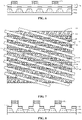
- FIG. 9 illustrates a schematic section view in the direction of the dotted line 30 and the direction of the dotted line 31.
- the bit line contact layers 121 are at different heights.
- the bit line contact layers 121 are at different heights, and protruding portions at a first height and sunken portions at a second height in the bit line contact layers 121 at the bit line contact openings 111 are alternately arranged.
- masks may further be continued to be formed.
- the bit line contact layers at different heights are further etched to ensure that heights of the top surfaces of the left bit line contact layers may be alternately arranged according to a preset height sequence.
- conducting layers 140 are formed on the top surfaces of the bit line contact layers 121 at different heights.
- conducting films 141 are formed on the top surfaces of the bit line contact layers 121 at different heights.
- the conducting films 141 are etched (referring to FIG. 10 ) to form the conducting layers 140 with the same thickness on the top surfaces of the bit line contact layers 121 at different heights.
- the conducting layers 140 with the same thickness are formed to ensure that the conducting layers 140 on the top surfaces of the bit line contact layers 121 at different heights are at different heights.
- the conducting layers on the top surfaces of the bit line contact layers at different heights may have different thicknesses, but it is necessary to ensure that the top surfaces of the conducting layers are at different heights, so that the connecting line of the conducting layers between different bit line structures is an oblique line, and distances between the conducting layers of the bit line structures are increased without changing an arrangement manner for the bit line structures.
- the top surfaces of the formed conducting layers 140 are at different heights, and the connecting line is waved.
- the top surfaces are at different heights, and the connecting line is waved.
- the conducting layer 140 is formed from one conducting material or more conducting materials, for example, doped with polysilicon, titanium, titanium nitride, tungsten, and a composite of tungsten.
- top dielectric layers 150 are formed on top surfaces of the conducting layers 140.
- top dielectric films are formed on the top surfaces of the conducting layers, and surfaces of the top dielectric films are planarized to form the top dielectric layers 150, top surfaces of the top dielectric layers 150 being at a same height.
- the top surfaces of the top dielectric films are planarized in a chemical mechanical polishing manner. Compared with an etching process, a chemical mechanical polishing process is higher in removal rate and favorable for shortening the process cycle.
- a material for the top dielectric layer 150 includes silicon nitride, silicon oxynitride, silicon oxide, etc.
- the material for the top dielectric layer 150 is a nitrogen-containing insulating material, namely silicon nitride is used for the top dielectric layer 150.
- part of the top dielectric layers 150, the conducting layers 140 and the bit line contact layers 121 at different heights are sequentially etched to form separate bit line structures 200.
- the connecting line of the conducting layers 140 in the separate bit line structures 200 is waved.
- the conducting layers 140 in adjacent separate bit line structures 200 are at different heights, and the connecting line of the conducting layers 140 is waved.
- the bit line contact layers at different heights are formed to make the conducting layers formed on the top surfaces of the bit line contact layers at different heights.
- the top surfaces of the conducting layers are at the same height in the direction perpendicular to the extension direction of the word line structure, and the top surfaces of the conducting layers are at different heights in the extension direction of the word line structure. That is, in the separate bit line structures that are subsequently formed, the conducting layers in the same bit line structure are at different heights, and the conducting layers in different bit line structures are at different heights.
- the conducting layers in adjacent separate bit line structures are formed at different heights without changing an arrangement manner for the bit line structures, and compared with the conducting layers at the same height, distances between the conducting layers at different heights change from horizontal distances to oblique distances, so that the distances between the conducting layers in the bit line structures are increased, furthermore, the parasitic capacitance between the bit line structures is reduced, and a saturation current of the memory is increased.
- the method for forming a memory provided in the examples is simple in flow, relatively low in cost, and easy to implement.
- a second example of the disclosure relates to a method for forming a memory.
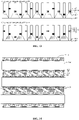
- the difference from the first example is that the example provides another manner for forming photolithographic masks. Referring to FIG. 14 and FIG. 15 , the method for forming a memory of the example will be specifically described below.
- Second photolithographic mask layers are formed on the top surfaces of the bit line contact layers.
- the example provides two manners for forming the second photolithographic mask layers, specifically as follows.
- the first manner for forming second photolithographic mask layers 500 is in the extension direction 10 of the word line structure, there are gaps formed between adjacent second photolithographic mask layers 500 in the direction perpendicular to the extension direction 10 of the word line structure, and spaces between at least two columns of word line structures 102 are exposed in the substrate at bottoms of the bit line contact layers exposed from the gaps.
- the second manner for forming second photolithographic mask layers 501 the second photolithographic mask layers 501 are formed, the second photolithographic mask layer 501 covering the two bit line contact points 502 in the space between the two columns of word line structures 102, and the second photolithographic mask layers 501 being sequentially arranged in the extension direction 10 of the word line structure.
- the second manner for forming the second photolithographic mask layers 501 is used, part of the bit line contact layers are etched based on the gaps to form the bit line contact layers at different heights, and then the second photolithographic mask layers are removed.
- the other process steps are the same as the first example.
- the bit line structure 200 formed according to the method for forming a mask provided in the example refers to FIG. 15 .
- the conducting layers in the bit line structures 200 formed in the bit line contact points covered by the second photolithographic mask layers are relatively high, and the conducting layers in the bit line structures 200 formed in the bit line contact points not covered by the second photolithographic mask layers are relatively low (not shown in the figure).
- the conducting layers in the bit line structures 200 on the bit line contact points are at the same height in the direction perpendicular to the extension direction 10 of the word line structure.
- the barrier layers are formed in the bit line contact layers, the bit line structures on the bottom dielectric layer 110 and the bit line structures on the bit line contact points are at different heights.
- the conducting layers in different bit line structures 200 are at different heights.
- the conducting layers in the same bit line structure 200 are at different heights due to the distribution of the second photolithographic mask layers.
- the bit line contact layers at different heights are formed to make the conducting layers formed on the top surfaces of the bit line contact layers at different heights.
- the top surfaces of the conducting layers are at the same height in the direction perpendicular to the extension direction of the word line structure, and the top surfaces of the conducting layers are at different heights in the extension direction of the word line structure. That is, in the separate bit line structures that are subsequently formed, the conducting layers in the same bit line structure are at different heights, and the conducting layers in different bit line structures are at different heights.
- the conducting layers in adjacent separate bit line structures are formed at different heights without changing an arrangement manner for the bit line structures, and compared with the conducting layers at the same height, distances between the conducting layers at different heights change from horizontal distances to oblique distances, so that the distances between the conducting layers in the bit line structures are increased, furthermore, the parasitic capacitance between the bit line structures is reduced, and a saturation current of the memory is increased.
- the method for forming a memory provided in the examples is simple in flow, relatively low in cost, and easy to implement.
- the first example corresponds to the present example, so that the present example can be matched with the first example for implementation.
- the related technical details mentioned in the first example are still effective in the present example, and the technical effects that may be achieved in the first example may also be achieved in the present example. For reducing repetitions, elaborations are omitted herein. Correspondingly, related technical details mentioned in the present example may also be applied to the first example.
- a third example of the disclosure relates to a memory.
- the memory includes: a substrate 100, at least word line structures 102 and active regions 101 being included in the substrate 100; a bottom dielectric layer 110, the bottom dielectric layer 110 being at a top of the substrate 100, bit line contact openings 111 being provided in the bottom dielectric layer 110, and the bit line contact openings 111 exposing the active regions 101 in the substrate 100; and separate bit line structures 200, top surfaces of the bit line structures 200 being at the same height, and the bit line structure 200 including a bit line contact layer 121 at a top of the bottom dielectric layer 110 and in the bit line contact opening 111, a conducting layer 140 at a top of the bit line contact layer 121, and a top dielectric layer 150 at a top of the conducting layer 140.
- the conducting layers 140 in the same bit line structure are at different heights in an extension direction 20 of the bit line structure, and the conducting layers 140 in adjacent bit line structures are at different heights in an extension direction 10 of the word line structure.
- memory structures except the word line structures 102 and the active regions 101, are also included in the substrate 100, such as shallow trench isolation structures, etc.
- the other memory structures do not involve the core technology of the disclosure, and will not be elaborated herein.
- the other memory structures for normal running of the memory except the word line structures 102 and the active regions 101, may also be included in the substrate 100.
- the conducting layers 140 have the same thickness.
- the conducting layers 140 on the top surfaces of the bit line contact layers 121 at different heights may have different thicknesses, but it is necessary to ensure that the top surfaces of the conducting layers 140 are at different heights, so that the connecting line of the conducting layers between different bit line structures is an oblique line, and distances between the conducting layers of the bit line structures are increased without changing an arrangement manner for the bit line structures.
- a connecting line of the conducting layers 140 is waved in the extension direction 20 of the bit line structure, namely the conducting layers 140 in the same bit line structure 200 are at different heights.
- the conducting layers 140 in different bit line structures 200 are at the same height in a preset direction, the preset direction forming an included angle ⁇ with the extension direction 10 of the word line structure, and a range of ⁇ being 0 ⁇ 90° (the included angle ⁇ between straight lines refers to an included angle between a straight line 40 and the straight line 10, and if it is an included angle of rays, the range of ⁇ is 0 ⁇ 360°, ⁇ 90°, ⁇ 180°, and ⁇ 270°).
- the example has the following advantages.
- the conducting layers on the top surfaces of the bit line contact layers are at different heights.
- the top surfaces of the conducting layers are at the same height in the direction perpendicular to the extension direction of the word line structure, and the top surfaces of the conducting layers are at different heights in the extension direction of the word line structure. That is, in the separate bit line structures that are subsequently formed, the conducting layers in the same bit line structure are at different heights, and the conducting layers in different bit line structures are at different heights.
- the conducting layers in adjacent separate bit line structures are formed at different heights without changing an arrangement manner for the bit line structures, and compared with the conducting layers at the same height, distances between the conducting layers at different heights change from horizontal distances to oblique distances, so that the distances between the conducting layers in the bit line structures are increased, furthermore, the parasitic capacitance between the bit line structures is reduced, and a saturation current of the memory is increased.
- the method for forming a memory provided in the examples is simple in flow, relatively low in cost, and easy to implement.
- the first example corresponds to the present example, so that the present example can be matched with the first example for implementation.
- the related technical details mentioned in the first example are still effective in the present example, and the technical effects that may be achieved in the first example may also be achieved in the present example. For reducing repetitions, elaborations are omitted herein. Correspondingly, related technical details mentioned in the present example may also be applied to the first example.
Landscapes
- Engineering & Computer Science (AREA)
- Microelectronics & Electronic Packaging (AREA)
- Computer Hardware Design (AREA)
- Manufacturing & Machinery (AREA)
- Semiconductor Memories (AREA)
- Internal Circuitry In Semiconductor Integrated Circuit Devices (AREA)
Abstract
Description
- This application claims priority to
Chinese Patent Application No. 202010575406.8, filed on June 22, 2020 - The disclosure relates to the technical field of semiconductors, and particularly to a method for forming a memory and a memory.
- With the constant decrease of a feature size and line width of a Dynamic Random Access Memory (DRAM), a distance between adjacent bit line structures also constantly decreases. Decrease of the distance between the adjacent bit line structures may cause constant increase of parasitic capacitance between the adjacent bit line structures, affect a saturation current of an array area of the DRAM, and further affect the running efficiency of the DRAM
- When a line width of a DRAM constantly decreases, how to increase a distance between bit line structures is a problem urgent to be solved at present.
- Part of examples of the disclosure are intended to provide a method for forming a memory and a memory. Conducting layers in bit line structures are formed at different heights to increase distances between the conducting layers in the bit line structures without changing an arrangement manner for the bit line structures.
- The examples of the disclosure provide a method for forming a memory, which may include that: a substrate in which at least word line structures and active regions are included, as well as a bottom dielectric layer and bit line contact layers that are on a top surface of the substrate, is provided, bit line contact openings being provided in the bottom dielectric layer, the bit line contact openings exposing the active regions in the substrate, and the bit line contact layers covering the bottom dielectric layer and filling the bit line contact openings; part of the bit line contact layers are etched to form bit line contact layers at different heights; conducting layers are formed on top surfaces of the bit line contact layers, top surfaces of the conducting layers being at different heights in a direction perpendicular to an extension direction of the word line structure, and the top surfaces of the conducting layers being at different heights in the extension direction of the word line structure; top dielectric layers are formed on the top surfaces of the conducting layers; and part of the top dielectric layers, the conducting layers and the bit line contact layers are etched sequentially to form separate bit line structures.
- In addition, the operation that part of the bit line contact layers are etched to form the bit line contact layers at different heights may include that: first photolithographic mask layers are formed on the top surfaces of the bit line contact layers; the first photolithographic mask layers are patterned to form spaced patterns in a preset direction, the preset direction forming an included angle α with the extension direction of the word line structure, and a range of α being 0<α<90°; part of the bit line contact layers are etched based on the spaced patterns to form the bit line contact layers at different heights; and the spaced patterns are removed.
- In addition, the spaced patterns may include spaced and extending strips, or separate ellipses or rectangles.
- In addition, the operation that part of the bit line contact layers are etched to form the bit line contact layers at different heights may include that: second photolithographic mask layers are formed on the top surfaces of the bit line contact layers, the second photolithographic mask layers being in the extension direction of the word line structure, there being gaps between adjacent second photolithographic mask layers in the direction perpendicular to the extension direction of the word line structure, and spaces between at least two columns of word line structures being comprised in the substrate at bottoms of the bit line contact layers exposed from the gaps; part of the bit line contact layers are etched based on the gaps to form the bit line contact layers at different heights; and the second photolithographic layers are removed.
- In addition, the operation that the conducting layers are formed on the top surfaces of the bit line contact layers may include that: conducting films are formed on the top surfaces of the bit line contact layers; and the conducting films are etched to form the conducting layers with the same thickness on the top surfaces of the bit line contact layers at different heights. The conducting layers with the same thickness are formed to ensure that the conducting layers on the top surfaces of the bit line contact layers at different heights are at different heights.
- In addition, the operation that the top dielectric layers are formed on the top surfaces of the conducting layers may include that: top dielectric films are formed on the top surfaces of the conducting layers; and top surfaces of the top dielectric films are planarized to form the top dielectric layers, top surfaces of the top dielectric layers being at a same height.
- In addition, the bit line contact layer filling the bit line contact opening and covering the bottom dielectric layer may include: a first bit line contact layer fill the bit line contact opening is formed, the first bit line contact layer covering the bottom dielectric layer; a barrier layer is formed on a top surface of the first bit line contact layer at a top of the bottom dielectric layer; and a second bit line contact layer is formed on a top surface of the barrier layer and the top surface of the first bit line contact layer, the second bit line contact layer covering the first bit line contact layer and the barrier layer. The barrier layers are formed in the bit line contact layers in a manner that the conducting layers formed by etching in the bit line structures at the top of the bottom dielectric layer are at the same height as the barrier layers, so that height differences between the conducting layers in different bit line structures are reduced, a connecting line of the conducting layers is waved, and furthermore, the structural stability of the memory is improved.
- The examples of the disclosure also provide a memory, which may include: a substrate, in which at least word line structures and active regions being included; a bottom dielectric layer, the bottom dielectric layer being at a top of the substrate, bit line contact openings being provided in the bottom dielectric layer, and the bit line contact openings exposing the active regions in the substrate; and separate bit line structures, top surfaces of the bit line structures being at the same height, and the bit line structure including a bit line contact layer at a top of the bottom dielectric layer and in the bit line contact opening, a conducting layer at a top of the bit line contact layer, and a top dielectric layer at a top of the conducting layer. The conducting layers in the same bit line structure may be at different heights in an extension direction of the bit line structure, and the conducting layers in adjacent bit line structures may be at different heights in an extension direction of the word line structure.
- In addition, a connecting line of the conducting layers may be waved in the extension direction of the bit line structure. Height differences of the conducting layers in different bit line structures are reduced to improve the structural stability of the memory.
- In addition, the conducting layers in different bit line structures may be at the same height in a preset direction, the preset direction forming an included angle α with the extension direction of the word line structure, and a range of α being 0<α<90°.
- Compared with the related art, the examples of the disclosure have the following advantages. The bit line contact layers at different heights are formed to make the conducting layers formed on the top surfaces of the bit line contact layers at different heights. The top surfaces of the conducting layers are at the same height in the direction perpendicular to the extension direction of the word line structure, and the top surfaces of the conducting layers are at different heights in the extension direction of the word line structure. That is, in the separate bit line structures that are subsequently formed, the conducting layers in the same bit line structure are at different heights, and the conducting layers in different bit line structures are at different heights. The conducting layers in adjacent separate bit line structures are formed at different heights without changing an arrangement manner for the bit line structures, and compared with the conducting layers at the same height, distances between the conducting layers at different heights change from horizontal distances to oblique distances, so that the distances between the conducting layers in the bit line structures are increased, furthermore, the parasitic capacitance between the bit line structures is reduced, and a saturation current of the memory is increased. In addition, the method for forming a memory provided in the examples is simple in flow, relatively low in cost, and easy to implement.
- Exemplary descriptions are made to one or more examples through the pictures in the corresponding accompanying drawings. Unless otherwise specified, the pictures in the accompanying drawings do not form scale limits.
-
FIG. 1 to FIG. 12 illustrate structure diagrams corresponding to each step of a method for forming a memory according to a first example of the disclosure. -
FIG. 13 illustrates a schematic section view of a memory formed according to the first example of the disclosure. -
FIG. 14 illustrates a structure diagram corresponding to another patterning manner in a method for forming a memory according to a second example of the disclosure. -
FIG. 15 illustrates a schematic section view of a memory formed according to the second example of the disclosure. - At present, with the constant decrease of a feature size and line width of a DRAM, a distance between adjacent bit line structures also constantly decreases. Decrease of the distance between the adjacent bit line structures may cause constant increase of parasitic capacitance between the adjacent bit line structures, affect a saturation current of an array area of the DRAM, and further affect the running efficiency of the DRAM
- For making the objectives, technical solutions and advantages of the disclosure clearer, part of examples of the disclosure will further be described below in detail in combination with the drawings and the examples. It should be understood that specific examples described here are only adopted to explain the disclosure and not intended to limit the disclosure.
- A first example of the disclosure relates to a method for forming a memory, which includes the following operations. A substrate is provided. At least word line structures and active regions are included in the substrate, a bottom dielectric layer and bit line contact layers are provided on a top surface of the substrate, bit line contact openings are formed in the bottom dielectric layer, the bit line contact openings expose the active regions in the substrate, and the bit line contact layers cover the bottom dielectric layer and fill the bit line contact openings. Part of the bit line contact layers are etched to form bit line contact layers at different heights. Conducting layers are formed on top surfaces of the bit line contact layers. Top surfaces of the conducting layers are at different heights in a direction perpendicular to an extension direction of the word line structure, and the top surfaces of the conducting layers are at different heights in the extension direction of the word line structure. Top dielectric layers are formed on the top surfaces of the conducting layers. Part of the top dielectric layers, the conducting layers and the bit line contact layers are etched to form separate bit line structures.
-
FIG. 1 to FIG. 12 illustrate structure diagrams corresponding to each step of a method for forming a memory according to a first example of the disclosure. The method for forming a memory of the example will be specifically described below. - Referring to
FIG. 1 to FIG. 5 , asubstrate 100 is provided. At leastword line structures 102 andactive regions 101 are included in thesubstrate 100, a bottomdielectric layer 110 and bitline contact layers 120 are provided on a top surface of thesubstrate 100, bitline contact openings 111 are provided in the dielectric layer, the bitline contact openings 111 expose theactive regions 101 in thesubstrate 100, and the bitline contact layers 120 cover the bottomdielectric layer 110 and fill the bitline contact openings 111. -
FIG. 1 to FIG. 5 will be described below in detail in combination with the drawings. - Referring to
FIG. 1 , thesubstrate 100 is provided. At least theword line structures 102 and theactive regions 101 are included in thesubstrate 100. -
FIG. 1 shows anextension direction 10 of the word line structure, i.e., thedotted line 10 in the figure. - Multiple
active regions 101 are spaced in parallel. Theactive regions 101 of an ith column and theactive regions 101 of an (i+3)th column are at the same horizontal position in a direction perpendicular to theextension direction 10 of the word line structure. Theactive regions 101 of the ith column and theactive regions 101 of adjacent columns (the (i+1)th column and an (i-1)th column) are at different horizontal positions in the direction perpendicular to theextension direction 10 of the word line structure. Bit line contact points are formed at middle portions of theactive regions 101 spaced by the alternately arrangedword line structures 102, and are used to connect bit line structures that are subsequently formed. - It is to be noted that other memory structures, except the
word line structures 102 and theactive regions 101, are also included in thesubstrate 100, such as shallow trench isolation structures, etc. The other memory structures do not involve the core technology of the disclosure, and will not be elaborated herein. Those skilled in the art can understood that the other memory structures for normal running of the memory, except theword line structures 102 and theactive regions 101, may also be included in thesubstrate 100. - A material for the
substrate 100 may include sapphire, silicon, silicon carbide, gallium arsenide, aluminum nitride, zinc oxide, etc. In the example, thesubstrate 100 is formed from silicon. Those skilled in the art knows that silicon is used as thesubstrate 100 in the example for a purpose of making it convenient for those skilled in the art to understand the subsequent forming method, no limits are formed, and a suitable material may be selected as the substrate as required in a practical application process. - Referring to
FIG. 2 to FIG. 5 , thebottom dielectric layer 110 and the bit line contact layers 120 are formed on the top surface of thesubstrate 100, the bitline contact openings 111 are provided in thebottom dielectric layer 110, the bitline contact openings 111 expose theactive regions 101 in thesubstrate 100, and the bit line contact layers 120 cover thebottom dielectric layer 110 and fill the bitline contact openings 111. - Referring to
FIG. 2 , thebottom dielectric layer 110 is formed on the top surface of thesubstrate 100, the bitline contact openings 111 are provided in thebottom dielectric layer 110, and the bitline contact openings 111 are formed to expose theactive regions 101 in thesubstrate 100. Specifically, the bitline contact openings 111 are formed to expose bit line contact points, namely exposing middle portions of theactive regions 101 spaced by theword line structures 102. - The
bottom dielectric layer 110 is used to isolate thebit line structures 200 not at the bit line contact points from contacting theactive regions 101. In the example, a material for the bottom dielectric layer is silicon nitride. In another example, the material for the bottom dielectric layer may also be an insulating material such as silicon oxide or silicon oxynitride. - Referring to
FIG. 3, FIG. 3 illustrates a top view of thesubstrate 100.FIG. 3 presents positions where thebit line structures 200 are required to be subsequently formed based on formation of the bottom dielectric layer inFIG. 2 .FIG. 3 shows anextension direction 20 of the bit line structure, i.e., the dottedline 20 in the figure. Thebit line structure 200 is connected with the bit line contact points of theactive regions 101 of a column. - Referring to
FIG. 4 , the bit line contact layers 120 are formed on the top surface of thesubstrate 100, and the bit line contact layers 120 cover thebottom dielectric layer 120 and fill the bitline contact openings 111.FIG. 4 presents positions where the bit line structures are required to be subsequently formed. In any section in theextension direction 10 of the word line structure, bit lines connected with theactive regions 101 and bit lines on thebottom dielectric layer 110 are alternately arranged. - In the example, the bit
line contact layer 120 includes a first bitline contact layer 122 and a second bitline contact layer 123. Specifically, the first bitline contact layer 122 filling the bitline contact opening 111 is formed, the first bitline contact layer 122 covering thebottom dielectric layer 110. Abarrier layer 124 is formed on a top surface of the first bitline contact layer 122 at a top of thebottom dielectric layer 110. The second bitline contact layer 123 is formed on a top surface of thebarrier layer 124 and the top surface of the first bitline contact layer 122, the second bitline contact layer 123 covering the first bitline contact layer 122 and thebarrier layer 124. The barrier layers 124 are formed in the bit line contact layers 120 in a manner that the conducting layers subsequently formed by etching in the bit line structures at the top of the bottom dielectric layer are at the same height as the barrier layers, so that height differences between the conducting layers in different bit line structures are reduced, a connecting line of the conducting layers is waved, and furthermore, the structural stability of the formed memory is improved. - In the example, a material for the
barrier layer 124 is the same as that for thebottom dielectric layer 110. In another example, it is only necessary to ensure that the material for the barrier layer is different from a material for the bit line contact layer to ensure that the barrier layers are etched when the bit line contact layers are etched. In addition, in the example, both the first bitline contact layer 122 and the second bitline contact layer 123 use a polysilicon material, and are used to connect the subsequently formedbit line structures 200 with theactive regions 101 in the substrate through the bitline contact openings 111. - It is to be noted that, in another example, the bit
line contact layer 120 may also be formed by a single-layer structure. The specific layer number of the bitline contact layer 120 is not limited in the example. Those skilled in the art can know that the multilayer structure solution provided in the abovementioned example is intended to ensure that height differences between the subsequently formed conducting layers at different heights are relatively small and the connecting line of the conducting layers is waved to improve the stability of the memory. - Referring to
FIG. 5 to FIG. 8 , part of the bit line contact layers 120 are etched to form bit line contact layers 121 at different heights. - A reason for forming the bit line contact layers 121 at different heights includes that the bit line contact layers 121 are used to ensure that the conducting layers are at different heights after the conducting layers are subsequently formed.
- Specifically, referring to
FIG. 5 , a firstphotolithographic mask layer 130 is formed on top surface of the bitline contact layer 120, and aphotoresist 140 is formed on a top surface of the firstphotolithographic mask layer 130. - Referring to
FIG. 6 , the first photolithographic mask layers 130 are patterned to form spacedpatterns 131 in a preset direction. The spacedpatterns 131 include spaced and extending strips, or separate ellipses or rectangles. - The first
photolithographic mask layer 130 is patterned based on the photoresist. Referring toFIG. 7 , the first photolithographic mask layers 130 are patterned to form the spacedpatterns 131 in the preset direction, the preset direction forming an included angle α with theextension direction 10 of the word line structure, and a range of α being 0<α<90° (the included angle α between straight lines refers to an included angle between astraight line 40 and thestraight line 10, and if it is an included angle of rays, the range of α is 0<α<360°, α≠90°, α≠180°, and α≠270°). The example is illustrated with the condition that α is 25° as an instance. In another example, α may be 10°, 20°, 30°, 40°, 50°, 60°, 70°, 80°, etc. In the figure, thecircles 401 represent the line bit contact points covered by the spacedpatterns 131. It can be seen by those skilled in the art that the bit line contact points covered by the spacedpatterns 131 and the bit line contact points not covered by the spacedpatterns 131 are alternately arranged in sectional directions of the dottedline 30 and the dottedline 31. - It is to be noted that, in the example, the spaced
patterns 131 are exemplarily described with spaced and extending strips as an instance. In another example, the spacedpatterns 131 may also be separate ellipses or rectangles. - Referring to
FIG. 8 , part of the bit line contact layers 120 are etched based on the spacedpatterns 131 to form the bit line contact layers 121 at different heights. - Referring to
FIG. 9 , the spacedpatterns 131 and the barrier layers 124 are removed. - In the figure, the direction of the dotted
line 30 and the direction of the dottedline 31 are two sectional positions presented inFIG. 3 , and are used for those skilled in the art to understand the principle of the disclosure. -
FIG. 9 illustrates a schematic section view in the direction of the dottedline 30 and the direction of the dottedline 31. In the direction perpendicular to theextension direction 10 of the word line structure (the same vertical position in the two figures), the bit line contact layers 121 are at different heights. In theextension direction 10 of the word line structure (the shown sectional direction), the bit line contact layers 121 are at different heights, and protruding portions at a first height and sunken portions at a second height in the bit line contact layers 121 at the bitline contact openings 111 are alternately arranged. - In another example, masks may further be continued to be formed. The bit line contact layers at different heights are further etched to ensure that heights of the top surfaces of the left bit line contact layers may be alternately arranged according to a preset height sequence.
- Referring to
FIG. 10 to FIG. 11 , conductinglayers 140 are formed on the top surfaces of the bit line contact layers 121 at different heights. - Specifically, referring to
FIG. 10 , conductingfilms 141 are formed on the top surfaces of the bit line contact layers 121 at different heights. - Referring to
FIG. 11 , the conductingfilms 141 are etched (referring toFIG. 10 ) to form the conductinglayers 140 with the same thickness on the top surfaces of the bit line contact layers 121 at different heights. The conducting layers 140 with the same thickness are formed to ensure that the conducting layers 140 on the top surfaces of the bit line contact layers 121 at different heights are at different heights. - In another example, the conducting layers on the top surfaces of the bit line contact layers at different heights may have different thicknesses, but it is necessary to ensure that the top surfaces of the conducting layers are at different heights, so that the connecting line of the conducting layers between different bit line structures is an oblique line, and distances between the conducting layers of the bit line structures are increased without changing an arrangement manner for the bit line structures.
- In the direction perpendicular to the
extension direction 10 of the word line structure, the top surfaces of the formed conductinglayers 140 are at different heights, and the connecting line is waved. In theextension direction 10 of the word line structure, the top surfaces are at different heights, and the connecting line is waved. - In the example, the
conducting layer 140 is formed from one conducting material or more conducting materials, for example, doped with polysilicon, titanium, titanium nitride, tungsten, and a composite of tungsten. - Referring to
FIG. 12 , topdielectric layers 150 are formed on top surfaces of the conducting layers 140. - Specifically, top dielectric films are formed on the top surfaces of the conducting layers, and surfaces of the top dielectric films are planarized to form the top
dielectric layers 150, top surfaces of the topdielectric layers 150 being at a same height. - Specifically, the top surfaces of the top dielectric films are planarized in a chemical mechanical polishing manner. Compared with an etching process, a chemical mechanical polishing process is higher in removal rate and favorable for shortening the process cycle.
- In the example, a material for the
top dielectric layer 150 includes silicon nitride, silicon oxynitride, silicon oxide, etc. In the example, the material for thetop dielectric layer 150 is a nitrogen-containing insulating material, namely silicon nitride is used for thetop dielectric layer 150. - Referring to
FIG. 13 , part of the topdielectric layers 150, the conductinglayers 140 and the bit line contact layers 121 at different heights are sequentially etched to form separatebit line structures 200. - In the direction perpendicular to the
extension direction 10 of the word line structure, the connecting line of the conductinglayers 140 in the separatebit line structures 200 is waved. In theextension direction 10 of the word line structure, the conductinglayers 140 in adjacent separatebit line structures 200 are at different heights, and the connecting line of the conducting layers 140 is waved. - Compared with the related art, the method for forming a memory provided in the examples of the disclosure has the following advantages. The bit line contact layers at different heights are formed to make the conducting layers formed on the top surfaces of the bit line contact layers at different heights. The top surfaces of the conducting layers are at the same height in the direction perpendicular to the extension direction of the word line structure, and the top surfaces of the conducting layers are at different heights in the extension direction of the word line structure. That is, in the separate bit line structures that are subsequently formed, the conducting layers in the same bit line structure are at different heights, and the conducting layers in different bit line structures are at different heights. The conducting layers in adjacent separate bit line structures are formed at different heights without changing an arrangement manner for the bit line structures, and compared with the conducting layers at the same height, distances between the conducting layers at different heights change from horizontal distances to oblique distances, so that the distances between the conducting layers in the bit line structures are increased, furthermore, the parasitic capacitance between the bit line structures is reduced, and a saturation current of the memory is increased. In addition, the method for forming a memory provided in the examples is simple in flow, relatively low in cost, and easy to implement.
- The above steps are divided only for clear description. During implementation, the steps can be combined into one step, or some steps may be split into multiple steps, and any solution including the same logical relationship falls within the scope of protection of the disclosure. Adding insignificant modifications to the flow or introducing insignificant designs without changing the core design of the flow falls within the scope of protection of the disclosure.
- A second example of the disclosure relates to a method for forming a memory. The difference from the first example is that the example provides another manner for forming photolithographic masks. Referring to
FIG. 14 andFIG. 15 , the method for forming a memory of the example will be specifically described below. - Second photolithographic mask layers are formed on the top surfaces of the bit line contact layers.
- The example provides two manners for forming the second photolithographic mask layers, specifically as follows.
- The first manner for forming second photolithographic mask layers 500: the formed second
photolithographic mask layer 500 is in theextension direction 10 of the word line structure, there are gaps formed between adjacent second photolithographic mask layers 500 in the direction perpendicular to theextension direction 10 of the word line structure, and spaces between at least two columns ofword line structures 102 are exposed in the substrate at bottoms of the bit line contact layers exposed from the gaps. - The second manner for forming second photolithographic mask layers 501: the second photolithographic mask layers 501 are formed, the second
photolithographic mask layer 501 covering the two bit line contact points 502 in the space between the two columns ofword line structures 102, and the second photolithographic mask layers 501 being sequentially arranged in theextension direction 10 of the word line structure. - In the example, the second manner for forming the second photolithographic mask layers 501 is used, part of the bit line contact layers are etched based on the gaps to form the bit line contact layers at different heights, and then the second photolithographic mask layers are removed. The other process steps are the same as the first example. The
bit line structure 200 formed according to the method for forming a mask provided in the example refers toFIG. 15 . - The conducting layers in the
bit line structures 200 formed in the bit line contact points covered by the second photolithographic mask layers are relatively high, and the conducting layers in thebit line structures 200 formed in the bit line contact points not covered by the second photolithographic mask layers are relatively low (not shown in the figure). In such case, the conducting layers in thebit line structures 200 on the bit line contact points are at the same height in the direction perpendicular to theextension direction 10 of the word line structure. However, since the barrier layers are formed in the bit line contact layers, the bit line structures on thebottom dielectric layer 110 and the bit line structures on the bit line contact points are at different heights. In such case, in theextension direction 10 of the word line structure, the conducting layers in differentbit line structures 200 are at different heights. In theextension direction 20 of the bit line structure, the conducting layers in the samebit line structure 200 are at different heights due to the distribution of the second photolithographic mask layers. - Compared with the related art, the method for forming a memory provided in the second example of the disclosure has the following advantages. The bit line contact layers at different heights are formed to make the conducting layers formed on the top surfaces of the bit line contact layers at different heights. The top surfaces of the conducting layers are at the same height in the direction perpendicular to the extension direction of the word line structure, and the top surfaces of the conducting layers are at different heights in the extension direction of the word line structure. That is, in the separate bit line structures that are subsequently formed, the conducting layers in the same bit line structure are at different heights, and the conducting layers in different bit line structures are at different heights. The conducting layers in adjacent separate bit line structures are formed at different heights without changing an arrangement manner for the bit line structures, and compared with the conducting layers at the same height, distances between the conducting layers at different heights change from horizontal distances to oblique distances, so that the distances between the conducting layers in the bit line structures are increased, furthermore, the parasitic capacitance between the bit line structures is reduced, and a saturation current of the memory is increased. In addition, the method for forming a memory provided in the examples is simple in flow, relatively low in cost, and easy to implement.
- The first example corresponds to the present example, so that the present example can be matched with the first example for implementation. The related technical details mentioned in the first example are still effective in the present example, and the technical effects that may be achieved in the first example may also be achieved in the present example. For reducing repetitions, elaborations are omitted herein. Correspondingly, related technical details mentioned in the present example may also be applied to the first example.
- A third example of the disclosure relates to a memory.
- Referring to
FIG. 13 , the memory provided in the example will be described below in detail in combination with the drawing. Parts the same as or corresponding to the first example will not be elaborated below. - The memory includes: a
substrate 100, at leastword line structures 102 andactive regions 101 being included in thesubstrate 100; abottom dielectric layer 110, thebottom dielectric layer 110 being at a top of thesubstrate 100, bitline contact openings 111 being provided in thebottom dielectric layer 110, and the bitline contact openings 111 exposing theactive regions 101 in thesubstrate 100; and separatebit line structures 200, top surfaces of thebit line structures 200 being at the same height, and thebit line structure 200 including a bitline contact layer 121 at a top of thebottom dielectric layer 110 and in the bitline contact opening 111, aconducting layer 140 at a top of the bitline contact layer 121, and atop dielectric layer 150 at a top of theconducting layer 140. The conducting layers 140 in the same bit line structure are at different heights in anextension direction 20 of the bit line structure, and the conductinglayers 140 in adjacent bit line structures are at different heights in anextension direction 10 of the word line structure. - It is to be noted that other memory structures, except the
word line structures 102 and theactive regions 101, are also included in thesubstrate 100, such as shallow trench isolation structures, etc. The other memory structures do not involve the core technology of the disclosure, and will not be elaborated herein. Those skilled in the art can understood that the other memory structures for normal running of the memory, except theword line structures 102 and theactive regions 101, may also be included in thesubstrate 100. - In the example, the conducting
layers 140 have the same thickness. In another example, the conductinglayers 140 on the top surfaces of the bit line contact layers 121 at different heights may have different thicknesses, but it is necessary to ensure that the top surfaces of the conductinglayers 140 are at different heights, so that the connecting line of the conducting layers between different bit line structures is an oblique line, and distances between the conducting layers of the bit line structures are increased without changing an arrangement manner for the bit line structures. - In the example, a connecting line of the conducting layers 140 is waved in the
extension direction 20 of the bit line structure, namely the conductinglayers 140 in the samebit line structure 200 are at different heights. The conducting layers 140 in differentbit line structures 200 are at the same height in a preset direction, the preset direction forming an included angle α with theextension direction 10 of the word line structure, and a range of α being 0<α<90° (the included angle α between straight lines refers to an included angle between astraight line 40 and thestraight line 10, and if it is an included angle of rays, the range of α is 0<α<360°, α≠90°, α≠180°, and α≠270°). - Compared with the related art, the example has the following advantages. Through the bit line contact layers at different heights, the conducting layers on the top surfaces of the bit line contact layers are at different heights. The top surfaces of the conducting layers are at the same height in the direction perpendicular to the extension direction of the word line structure, and the top surfaces of the conducting layers are at different heights in the extension direction of the word line structure. That is, in the separate bit line structures that are subsequently formed, the conducting layers in the same bit line structure are at different heights, and the conducting layers in different bit line structures are at different heights. The conducting layers in adjacent separate bit line structures are formed at different heights without changing an arrangement manner for the bit line structures, and compared with the conducting layers at the same height, distances between the conducting layers at different heights change from horizontal distances to oblique distances, so that the distances between the conducting layers in the bit line structures are increased, furthermore, the parasitic capacitance between the bit line structures is reduced, and a saturation current of the memory is increased. In addition, the method for forming a memory provided in the examples is simple in flow, relatively low in cost, and easy to implement.
- The first example corresponds to the present example, so that the present example can be matched with the first example for implementation. The related technical details mentioned in the first example are still effective in the present example, and the technical effects that may be achieved in the first example may also be achieved in the present example. For reducing repetitions, elaborations are omitted herein. Correspondingly, related technical details mentioned in the present example may also be applied to the first example.
- Those of ordinary skill in the art can understand that each example is a specific example implementing the disclosure, and in practical applications, various variations about the form and details can be made thereto without departing from the spirit and scope of the disclosure.
Claims (10)
- A method for forming a memory, comprising:providing a substrate, in which at least word line structures and active regions are comprised, as well as a bottom dielectric layer and bit line contact layers that are on a top surface of the substrate, bit line contact openings being provided in the bottom dielectric layer, the bit line contact openings exposing the active regions in the substrate, and the bit line contact layers covering the bottom dielectric layer and filling the bit line contact openings;etching part of the bit line contact layers to form bit line contact layers at different heights;forming conducting layers on top surfaces of the bit line contact layers, top surfaces of the conducting layers being at different heights in a direction perpendicular to an extension direction of the word line structure, and the top surfaces of the conducting layers being at different heights in the extension direction of the word line structure;forming top dielectric layers on the top surfaces of the conducting layers; andsequentially etching part of the top dielectric layers, the conducting layers and the bit line contact layers to form separate bit line structures.
- The method for forming a memory of claim 1, wherein etching part of the bit line contact layers to form the bit line contact layers at different heights comprises:forming first photolithographic mask layers on the top surfaces of the bit line contact layers;patterning the first photolithographic mask layers to form spaced patterns in a preset direction,the preset direction forming an included angle α with the extension direction of the word line structure, and a range of α being 0<α<90°;etching part of the bit line contact layers based on the spaced patterns to form the bit line contact layers at different heights; andremoving the spaced patterns.
- The method for forming a memory of claim 2, wherein the spaced patterns comprise spaced and extending strips, or separate ellipses or rectangles.
- The method for forming a memory of claim 1, wherein etching part of the bit line contact layers to form the bit line contact layers at different heights comprises:forming second photolithographic mask layers on the top surfaces of the bit line contact layers,the second photolithographic mask layers being in the extension direction of the word line structure, and there being gaps formed between adjacent second photolithographic mask layers in the direction perpendicular to the extension direction of the word line structure,wherein spaces between at least two columns of word line structures are comprised in the substrate at bottoms of the bit line contact layers exposed from the gaps;etching part of the bit line contact layers based on the gaps to form the bit line contact layers at different heights; andremoving the second photolithographic mask layers.
- The method for forming a memory of claim 1, wherein forming the conducting layers on the top surfaces of the bit line contact layers comprises:forming conducting films on the top surfaces of the bit line contact layers; andetching the conducting films to form the conducting layers with a same thickness on the top surfaces of the bit line contact layers at different heights.
- The method for forming a memory of claim 1, wherein forming the top dielectric layers on the top surfaces of the conducting layers comprises:forming top dielectric films on the top surfaces of the conducting layers; andplanarizing top surfaces of the top dielectric films to form the top dielectric layers, top surfaces of the top dielectric layers being at a same height.
- The method for forming a memory of any one of claims 1-6, wherein the bit line contact layer filling the bit line contact opening and covering the bottom dielectric layer comprises:forming a first bit line contact layer filling the bit line contact opening, the first bit line contact layer covering the bottom dielectric layer;forming a barrier layer on a top surface of the first bit line contact layer at a top of the bottom dielectric layer; andforming a second bit line contact layer on a top surface of the barrier layer and the top surface of the first bit line contact layer, the second bit line contact layer covering the first bit line contact layer and the barrier layer.
- A memory, comprising:a substrate, at least word line structures and active regions being comprised in the substrate;a bottom dielectric layer, the bottom dielectric layer being at a top of the substrate, bit line contact openings being provided in the bottom dielectric layer, and the bit line contact openings exposing the active regions in the substrate; andseparate bit line structures, top surfaces of the bit line structures being at the same height, and the bit line structure comprising a bit line contact layer at a top of the bottom dielectric layer and in the bit line contact opening, a conducting layer at a top of the bit line contact layer, and a top dielectric layer at a top of the conducting layer,wherein the conducting layers in the same bit line structure are at different heights in an extension direction of the bit line structure, and the conducting layers in adjacent bit line structures are at different heights in an extension direction of the word line structure.
- The memory of claim 8, wherein a connecting line of the conducting layers is waved in the extension direction of the bit line structure.
- The memory of claim 8, wherein the conducting layers in different bit line structures are at the same height in a preset direction, the preset direction forming an included angle α with the extension direction of the word line structure, and a range of α being 0<α<90°.
Applications Claiming Priority (2)
| Application Number | Priority Date | Filing Date | Title |
|---|---|---|---|
| CN202010575406.8A CN113903708B (en) | 2020-06-22 | 2020-06-22 | Memory forming method and memory |
| PCT/CN2020/115396 WO2021258560A1 (en) | 2020-06-22 | 2020-09-15 | Memory forming method and memory |
Publications (3)
| Publication Number | Publication Date |
|---|---|
| EP4099386A1 true EP4099386A1 (en) | 2022-12-07 |
| EP4099386A4 EP4099386A4 (en) | 2023-08-23 |
| EP4099386B1 EP4099386B1 (en) | 2025-04-09 |
Family
ID=79022299
Family Applications (1)
| Application Number | Title | Priority Date | Filing Date |
|---|---|---|---|
| EP20942150.2A Active EP4099386B1 (en) | 2020-06-22 | 2020-09-15 | Memory forming method and memory |
Country Status (4)
| Country | Link |
|---|---|
| US (1) | US12178036B2 (en) |
| EP (1) | EP4099386B1 (en) |
| JP (1) | JP7487324B2 (en) |
| KR (1) | KR102831626B1 (en) |
Families Citing this family (2)
| Publication number | Priority date | Publication date | Assignee | Title |
|---|---|---|---|---|
| CN114068420B (en) * | 2020-08-05 | 2024-06-07 | 长鑫存储技术有限公司 | Memory forming method and memory |
| US11910595B2 (en) * | 2021-07-06 | 2024-02-20 | Fujian Jinhua Integrated Circuit Co., Ltd. | Semiconductor memory device |
Family Cites Families (20)
| Publication number | Priority date | Publication date | Assignee | Title |
|---|---|---|---|---|
| JPH04340271A (en) * | 1991-02-07 | 1992-11-26 | Nec Corp | Semiconductor memory and manufacture thereof |
| KR100486300B1 (en) | 2003-01-14 | 2005-04-29 | 삼성전자주식회사 | Method for fabricating semiconductor device wherein bit-lines are formed by damascene technique |
| US7139184B2 (en) | 2004-12-07 | 2006-11-21 | Infineon Technologies Ag | Memory cell array |
| KR100689712B1 (en) | 2006-03-23 | 2007-03-08 | 삼성전자주식회사 | Method for manufacturing semiconductor memory device and its structure |
| KR100855579B1 (en) | 2006-10-02 | 2008-09-03 | 삼성전자주식회사 | Semiconductor memory device and forming method thereof |
| KR20080092557A (en) * | 2007-04-12 | 2008-10-16 | 주식회사 하이닉스반도체 | Wiring Formation Method of Semiconductor Device |
| KR100976682B1 (en) | 2008-04-04 | 2010-08-18 | 주식회사 하이닉스반도체 | Semiconductor memory device and manufacturing method thereof |
| KR20090111050A (en) * | 2008-04-21 | 2009-10-26 | 주식회사 하이닉스반도체 | Semiconductor device and manufacturing method thereof |
| KR20090111051A (en) * | 2008-04-21 | 2009-10-26 | 주식회사 하이닉스반도체 | Semiconductor device and manufacturing method thereof |
| KR101648128B1 (en) | 2009-12-28 | 2016-08-24 | 삼성전자주식회사 | Method for forming fine pattern having variable width and method for manufacturing semiconductor device using the same |
| KR101610831B1 (en) * | 2010-02-09 | 2016-04-12 | 삼성전자주식회사 | Semiconductor device having bit line interconnection with enlarged width and lowered level on bit line contact and fabricating methods of the same |
| KR101658492B1 (en) | 2010-08-13 | 2016-09-21 | 삼성전자주식회사 | Method for forming fine patterns and method for manufacturing a semiconductor device by using the same |
| JP5897479B2 (en) * | 2013-02-19 | 2016-03-30 | 株式会社東芝 | Semiconductor device and manufacturing method thereof |
| KR102630510B1 (en) | 2017-09-19 | 2024-01-30 | 삼성전자주식회사 | Semiconductor memory device and method of forming the same |
| KR102396583B1 (en) | 2017-11-09 | 2022-05-11 | 삼성전자주식회사 | Memory device and method of manufacturing the same |
| CN107910330B (en) | 2017-11-29 | 2023-09-19 | 长鑫存储技术有限公司 | Dynamic random access memory array and its layout structure and manufacturing method |
| CN208368506U (en) * | 2018-06-20 | 2019-01-11 | 长鑫存储技术有限公司 | A semiconductor memory structure |
| CN210325787U (en) * | 2019-09-17 | 2020-04-14 | 福建省晋华集成电路有限公司 | Bit line structure and semiconductor memory |
| CN110556359B (en) * | 2019-09-17 | 2024-12-20 | 福建省晋华集成电路有限公司 | A bit line structure and semiconductor memory |
| CN113903709B (en) * | 2020-06-22 | 2024-08-02 | 长鑫存储技术有限公司 | Memory forming method and memory |
-
2020
- 2020-09-15 KR KR1020227038285A patent/KR102831626B1/en active Active
- 2020-09-15 EP EP20942150.2A patent/EP4099386B1/en active Active
- 2020-09-15 JP JP2022552654A patent/JP7487324B2/en active Active
-
2021
- 2021-07-09 US US17/371,267 patent/US12178036B2/en active Active
Also Published As
| Publication number | Publication date |
|---|---|
| JP2023517007A (en) | 2023-04-21 |
| KR20220163433A (en) | 2022-12-09 |
| EP4099386A4 (en) | 2023-08-23 |
| EP4099386B1 (en) | 2025-04-09 |
| JP7487324B2 (en) | 2024-05-20 |
| US20210398984A1 (en) | 2021-12-23 |
| KR102831626B1 (en) | 2025-07-07 |
| US12178036B2 (en) | 2024-12-24 |
Similar Documents
| Publication | Publication Date | Title |
|---|---|---|
| US12417977B2 (en) | Semiconductor device and method of fabricating same | |
| US20150004774A1 (en) | Methods of fabricating a semiconductor device including fine patterns | |
| TWI271806B (en) | Method for fabricating semiconductor device | |
| US20020105088A1 (en) | Semiconductor device having multilayer interconnection structure and manfacturing method thereof | |
| KR102766910B1 (en) | Semiconductor device with support pattern, and method of fabricating the same | |
| US12342535B2 (en) | Memory forming method and memory | |
| US12114486B2 (en) | Semiconductor structure and method for forming the same | |
| JP2016033968A (en) | Method of manufacturing semiconductor device | |
| CN113707611B (en) | Formation method of memory and memory | |
| KR0138317B1 (en) | Semiconductor device capacitor manufacturing method | |
| EP4099386B1 (en) | Memory forming method and memory | |
| EP4287256B1 (en) | MANUFACTURING PROCESS FOR A SEMICONDUCTOR STRUCTURE | |
| US6844229B2 (en) | Method of manufacturing semiconductor device having storage electrode of capacitor | |
| US12205893B2 (en) | Method for forming semiconductor structure and semiconductor structure | |
| US12324148B2 (en) | Method for forming semiconductor structure and a semiconductor | |
| US12127397B2 (en) | Memory device and method for forming the same | |
| CN116801611A (en) | Memory, semiconductor structure and preparation method thereof | |
| WO2023019523A1 (en) | Semiconductor device, electronic device, and preparation method | |
| KR100333541B1 (en) | Manufacturing method of semiconductor device | |
| US20260068259A1 (en) | Method for manufacturing semiconductor device | |
| US20240268100A1 (en) | Semiconductor structure and method for forming the same | |
| KR100682166B1 (en) | Manufacturing method of semiconductor device | |
| KR101733771B1 (en) | Semiconductor device and method for fabricating the same | |
| WO2021258560A1 (en) | Memory forming method and memory | |
| WO2023221311A1 (en) | Semiconductor structure and forming method therefor |
Legal Events
| Date | Code | Title | Description |
|---|---|---|---|
| STAA | Information on the status of an ep patent application or granted ep patent |
Free format text: STATUS: THE INTERNATIONAL PUBLICATION HAS BEEN MADE |
|
| PUAI | Public reference made under article 153(3) epc to a published international application that has entered the european phase |
Free format text: ORIGINAL CODE: 0009012 |
|
| STAA | Information on the status of an ep patent application or granted ep patent |
Free format text: STATUS: REQUEST FOR EXAMINATION WAS MADE |
|
| 17P | Request for examination filed |
Effective date: 20220901 |
|
| AK | Designated contracting states |
Kind code of ref document: A1 Designated state(s): AL AT BE BG CH CY CZ DE DK EE ES FI FR GB GR HR HU IE IS IT LI LT LU LV MC MK MT NL NO PL PT RO RS SE SI SK SM TR |
|
| REG | Reference to a national code |
Ref country code: DE Ref legal event code: R079 Free format text: PREVIOUS MAIN CLASS: H01L0027115000 Ipc: H10B0012000000 Ref country code: DE Ref legal event code: R079 Ref document number: 602020049365 Country of ref document: DE Free format text: PREVIOUS MAIN CLASS: H01L0027115000 Ipc: H10B0012000000 |
|
| A4 | Supplementary search report drawn up and despatched |
Effective date: 20230720 |
|
| RIC1 | Information provided on ipc code assigned before grant |
Ipc: H01L 21/336 20060101ALI20230714BHEP Ipc: H10B 12/00 20230101AFI20230714BHEP |
|
| DAV | Request for validation of the european patent (deleted) | ||
| DAX | Request for extension of the european patent (deleted) | ||
| STAA | Information on the status of an ep patent application or granted ep patent |
Free format text: STATUS: EXAMINATION IS IN PROGRESS |
|
| 17Q | First examination report despatched |
Effective date: 20240624 |
|
| GRAP | Despatch of communication of intention to grant a patent |
Free format text: ORIGINAL CODE: EPIDOSNIGR1 |
|
| STAA | Information on the status of an ep patent application or granted ep patent |
Free format text: STATUS: GRANT OF PATENT IS INTENDED |
|
| RIC1 | Information provided on ipc code assigned before grant |
Ipc: H10D 30/01 20250101ALI20250107BHEP Ipc: H10B 12/00 20230101AFI20250107BHEP |
|
| INTG | Intention to grant announced |
Effective date: 20250116 |
|
| GRAS | Grant fee paid |
Free format text: ORIGINAL CODE: EPIDOSNIGR3 |
|
| GRAA | (expected) grant |
Free format text: ORIGINAL CODE: 0009210 |
|
| STAA | Information on the status of an ep patent application or granted ep patent |
Free format text: STATUS: THE PATENT HAS BEEN GRANTED |
|
| P01 | Opt-out of the competence of the unified patent court (upc) registered |
Free format text: CASE NUMBER: APP_7119/2025 Effective date: 20250212 |
|
| AK | Designated contracting states |
Kind code of ref document: B1 Designated state(s): AL AT BE BG CH CY CZ DE DK EE ES FI FR GB GR HR HU IE IS IT LI LT LU LV MC MK MT NL NO PL PT RO RS SE SI SK SM TR |
|
| REG | Reference to a national code |
Ref country code: GB Ref legal event code: FG4D |
|
| REG | Reference to a national code |
Ref country code: CH Ref legal event code: EP |
|
| REG | Reference to a national code |
Ref country code: DE Ref legal event code: R096 Ref document number: 602020049365 Country of ref document: DE |
|
| REG | Reference to a national code |
Ref country code: IE Ref legal event code: FG4D |
|
| REG | Reference to a national code |
Ref country code: NL Ref legal event code: MP Effective date: 20250409 |
|
| PG25 | Lapsed in a contracting state [announced via postgrant information from national office to epo] |
Ref country code: NL Free format text: LAPSE BECAUSE OF FAILURE TO SUBMIT A TRANSLATION OF THE DESCRIPTION OR TO PAY THE FEE WITHIN THE PRESCRIBED TIME-LIMIT Effective date: 20250409 |
|
| REG | Reference to a national code |
Ref country code: AT Ref legal event code: MK05 Ref document number: 1784812 Country of ref document: AT Kind code of ref document: T Effective date: 20250409 |
|
| PG25 | Lapsed in a contracting state [announced via postgrant information from national office to epo] |
Ref country code: PT Free format text: LAPSE BECAUSE OF FAILURE TO SUBMIT A TRANSLATION OF THE DESCRIPTION OR TO PAY THE FEE WITHIN THE PRESCRIBED TIME-LIMIT Effective date: 20250811 Ref country code: ES Free format text: LAPSE BECAUSE OF FAILURE TO SUBMIT A TRANSLATION OF THE DESCRIPTION OR TO PAY THE FEE WITHIN THE PRESCRIBED TIME-LIMIT Effective date: 20250409 Ref country code: FI Free format text: LAPSE BECAUSE OF FAILURE TO SUBMIT A TRANSLATION OF THE DESCRIPTION OR TO PAY THE FEE WITHIN THE PRESCRIBED TIME-LIMIT Effective date: 20250409 |
|
| PGFP | Annual fee paid to national office [announced via postgrant information from national office to epo] |
Ref country code: DE Payment date: 20250919 Year of fee payment: 6 |
|
| REG | Reference to a national code |
Ref country code: LT Ref legal event code: MG9D |
|
| PG25 | Lapsed in a contracting state [announced via postgrant information from national office to epo] |
Ref country code: NO Free format text: LAPSE BECAUSE OF FAILURE TO SUBMIT A TRANSLATION OF THE DESCRIPTION OR TO PAY THE FEE WITHIN THE PRESCRIBED TIME-LIMIT Effective date: 20250709 Ref country code: GR Free format text: LAPSE BECAUSE OF FAILURE TO SUBMIT A TRANSLATION OF THE DESCRIPTION OR TO PAY THE FEE WITHIN THE PRESCRIBED TIME-LIMIT Effective date: 20250710 |
|
| PG25 | Lapsed in a contracting state [announced via postgrant information from national office to epo] |
Ref country code: PL Free format text: LAPSE BECAUSE OF FAILURE TO SUBMIT A TRANSLATION OF THE DESCRIPTION OR TO PAY THE FEE WITHIN THE PRESCRIBED TIME-LIMIT Effective date: 20250409 |
|
| PG25 | Lapsed in a contracting state [announced via postgrant information from national office to epo] |
Ref country code: BG Free format text: LAPSE BECAUSE OF FAILURE TO SUBMIT A TRANSLATION OF THE DESCRIPTION OR TO PAY THE FEE WITHIN THE PRESCRIBED TIME-LIMIT Effective date: 20250409 |
|
| PG25 | Lapsed in a contracting state [announced via postgrant information from national office to epo] |
Ref country code: HR Free format text: LAPSE BECAUSE OF FAILURE TO SUBMIT A TRANSLATION OF THE DESCRIPTION OR TO PAY THE FEE WITHIN THE PRESCRIBED TIME-LIMIT Effective date: 20250409 |
|
| PG25 | Lapsed in a contracting state [announced via postgrant information from national office to epo] |
Ref country code: AT Free format text: LAPSE BECAUSE OF FAILURE TO SUBMIT A TRANSLATION OF THE DESCRIPTION OR TO PAY THE FEE WITHIN THE PRESCRIBED TIME-LIMIT Effective date: 20250409 |
|
| PG25 | Lapsed in a contracting state [announced via postgrant information from national office to epo] |
Ref country code: RS Free format text: LAPSE BECAUSE OF FAILURE TO SUBMIT A TRANSLATION OF THE DESCRIPTION OR TO PAY THE FEE WITHIN THE PRESCRIBED TIME-LIMIT Effective date: 20250709 |
|
| PG25 | Lapsed in a contracting state [announced via postgrant information from national office to epo] |
Ref country code: IS Free format text: LAPSE BECAUSE OF FAILURE TO SUBMIT A TRANSLATION OF THE DESCRIPTION OR TO PAY THE FEE WITHIN THE PRESCRIBED TIME-LIMIT Effective date: 20250809 |
|
| PG25 | Lapsed in a contracting state [announced via postgrant information from national office to epo] |
Ref country code: LV Free format text: LAPSE BECAUSE OF FAILURE TO SUBMIT A TRANSLATION OF THE DESCRIPTION OR TO PAY THE FEE WITHIN THE PRESCRIBED TIME-LIMIT Effective date: 20250409 |
|
| REG | Reference to a national code |
Ref country code: DE Ref legal event code: R097 Ref document number: 602020049365 Country of ref document: DE |
|
| PG25 | Lapsed in a contracting state [announced via postgrant information from national office to epo] |
Ref country code: DK Free format text: LAPSE BECAUSE OF FAILURE TO SUBMIT A TRANSLATION OF THE DESCRIPTION OR TO PAY THE FEE WITHIN THE PRESCRIBED TIME-LIMIT Effective date: 20250409 Ref country code: SM Free format text: LAPSE BECAUSE OF FAILURE TO SUBMIT A TRANSLATION OF THE DESCRIPTION OR TO PAY THE FEE WITHIN THE PRESCRIBED TIME-LIMIT Effective date: 20250409 |
|
| PG25 | Lapsed in a contracting state [announced via postgrant information from national office to epo] |
Ref country code: CZ Free format text: LAPSE BECAUSE OF FAILURE TO SUBMIT A TRANSLATION OF THE DESCRIPTION OR TO PAY THE FEE WITHIN THE PRESCRIBED TIME-LIMIT Effective date: 20250409 |
|
| PG25 | Lapsed in a contracting state [announced via postgrant information from national office to epo] |
Ref country code: EE Free format text: LAPSE BECAUSE OF FAILURE TO SUBMIT A TRANSLATION OF THE DESCRIPTION OR TO PAY THE FEE WITHIN THE PRESCRIBED TIME-LIMIT Effective date: 20250409 |
|
| PG25 | Lapsed in a contracting state [announced via postgrant information from national office to epo] |
Ref country code: SK Free format text: LAPSE BECAUSE OF FAILURE TO SUBMIT A TRANSLATION OF THE DESCRIPTION OR TO PAY THE FEE WITHIN THE PRESCRIBED TIME-LIMIT Effective date: 20250409 |
|
| PG25 | Lapsed in a contracting state [announced via postgrant information from national office to epo] |
Ref country code: IT Free format text: LAPSE BECAUSE OF FAILURE TO SUBMIT A TRANSLATION OF THE DESCRIPTION OR TO PAY THE FEE WITHIN THE PRESCRIBED TIME-LIMIT Effective date: 20250409 |
|
| PG25 | Lapsed in a contracting state [announced via postgrant information from national office to epo] |
Ref country code: RO Free format text: LAPSE BECAUSE OF FAILURE TO SUBMIT A TRANSLATION OF THE DESCRIPTION OR TO PAY THE FEE WITHIN THE PRESCRIBED TIME-LIMIT Effective date: 20250409 |
|
| PLBE | No opposition filed within time limit |
Free format text: ORIGINAL CODE: 0009261 |
|
| STAA | Information on the status of an ep patent application or granted ep patent |
Free format text: STATUS: NO OPPOSITION FILED WITHIN TIME LIMIT |
|
| REG | Reference to a national code |
Ref country code: CH Ref legal event code: L10 Free format text: ST27 STATUS EVENT CODE: U-0-0-L10-L00 (AS PROVIDED BY THE NATIONAL OFFICE) Effective date: 20260218 |
|
| 26N | No opposition filed |
Effective date: 20260112 |
|
| REG | Reference to a national code |
Ref country code: CH Ref legal event code: H13 Free format text: ST27 STATUS EVENT CODE: U-0-0-H10-H13 (AS PROVIDED BY THE NATIONAL OFFICE) Effective date: 20260504 |