EP4099355B1 - Elektrischer schalter - Google Patents
Elektrischer schalter Download PDFInfo
- Publication number
- EP4099355B1 EP4099355B1 EP21177117.5A EP21177117A EP4099355B1 EP 4099355 B1 EP4099355 B1 EP 4099355B1 EP 21177117 A EP21177117 A EP 21177117A EP 4099355 B1 EP4099355 B1 EP 4099355B1
- Authority
- EP
- European Patent Office
- Prior art keywords
- contact
- electrical switch
- movable
- adjustment member
- operating
- Prior art date
- Legal status (The legal status is an assumption and is not a legal conclusion. Google has not performed a legal analysis and makes no representation as to the accuracy of the status listed.)
- Active
Links
Images


Classifications
-
- H—ELECTRICITY
- H01—ELECTRIC ELEMENTS
- H01H—ELECTRIC SWITCHES; RELAYS; SELECTORS; EMERGENCY PROTECTIVE DEVICES
- H01H7/00—Devices for introducing a predetermined time delay between the initiation of the switching operation and the opening or closing of the contacts
-
- H—ELECTRICITY
- H01—ELECTRIC ELEMENTS
- H01H—ELECTRIC SWITCHES; RELAYS; SELECTORS; EMERGENCY PROTECTIVE DEVICES
- H01H9/00—Details of switching devices, not covered by groups H01H1/00 - H01H7/00
- H01H9/54—Circuit arrangements not adapted to a particular application of the switching device and for which no provision exists elsewhere
- H01H9/56—Circuit arrangements not adapted to a particular application of the switching device and for which no provision exists elsewhere for ensuring operation of the switch at a predetermined point in the AC cycle
-
- H—ELECTRICITY
- H01—ELECTRIC ELEMENTS
- H01H—ELECTRIC SWITCHES; RELAYS; SELECTORS; EMERGENCY PROTECTIVE DEVICES
- H01H1/00—Contacts
- H01H1/12—Contacts characterised by the manner in which co-operating contacts engage
- H01H1/14—Contacts characterised by the manner in which co-operating contacts engage by abutting
-
- H—ELECTRICITY
- H01—ELECTRIC ELEMENTS
- H01H—ELECTRIC SWITCHES; RELAYS; SELECTORS; EMERGENCY PROTECTIVE DEVICES
- H01H1/00—Contacts
-
- H—ELECTRICITY
- H01—ELECTRIC ELEMENTS
- H01H—ELECTRIC SWITCHES; RELAYS; SELECTORS; EMERGENCY PROTECTIVE DEVICES
- H01H1/00—Contacts
- H01H1/58—Electric connections to or between contacts; Terminals
-
- H—ELECTRICITY
- H01—ELECTRIC ELEMENTS
- H01H—ELECTRIC SWITCHES; RELAYS; SELECTORS; EMERGENCY PROTECTIVE DEVICES
- H01H9/00—Details of switching devices, not covered by groups H01H1/00 - H01H7/00
- H01H9/02—Bases, casings, or covers
-
- H—ELECTRICITY
- H01—ELECTRIC ELEMENTS
- H01H—ELECTRIC SWITCHES; RELAYS; SELECTORS; EMERGENCY PROTECTIVE DEVICES
- H01H2235/00—Springs
- H01H2235/01—Spiral spring
-
- H—ELECTRICITY
- H01—ELECTRIC ELEMENTS
- H01H—ELECTRIC SWITCHES; RELAYS; SELECTORS; EMERGENCY PROTECTIVE DEVICES
- H01H3/00—Mechanisms for operating contacts
- H01H3/32—Driving mechanisms, i.e. for transmitting driving force to the contacts
-
- H—ELECTRICITY
- H01—ELECTRIC ELEMENTS
- H01H—ELECTRIC SWITCHES; RELAYS; SELECTORS; EMERGENCY PROTECTIVE DEVICES
- H01H7/00—Devices for introducing a predetermined time delay between the initiation of the switching operation and the opening or closing of the contacts
- H01H7/16—Devices for ensuring operation of the switch at a predetermined point in the AC cycle
-
- H—ELECTRICITY
- H01—ELECTRIC ELEMENTS
- H01H—ELECTRIC SWITCHES; RELAYS; SELECTORS; EMERGENCY PROTECTIVE DEVICES
- H01H9/00—Details of switching devices, not covered by groups H01H1/00 - H01H7/00
- H01H9/54—Circuit arrangements not adapted to a particular application of the switching device and for which no provision exists elsewhere
- H01H9/56—Circuit arrangements not adapted to a particular application of the switching device and for which no provision exists elsewhere for ensuring operation of the switch at a predetermined point in the AC cycle
- H01H9/563—Circuit arrangements not adapted to a particular application of the switching device and for which no provision exists elsewhere for ensuring operation of the switch at a predetermined point in the AC cycle for multipolar switches, e.g. different timing for different phases, selecting phase with first zero-crossing
Definitions
- the present invention relates to an electrical switch.
- a neutral pole is adapted to disconnect simultaneously with phase poles during an opening event.
- a neutral pole is adapted to disconnect later than phase poles during an opening event.
- an electrical switch with a simultaneous break mechanism and an electrical switch with a late-break mechanism such that they both are based on the same phase pole unit, and the type of the electrical switch depends on a type of a neutral pole unit connected to the phase pole unit.
- the electrical switch with the simultaneous break mechanism is provided by combining the phase pole unit with a neutral pole unit of a simultaneous break type
- the electrical switch with the late-break mechanism is provided by combining the phase pole unit with a neutral pole unit of a late-break type.
- An object of the present invention is to provide an electrical switch so as to alleviate the above disadvantage.
- the objects of the invention are achieved by an electrical switch which is characterized by what is stated in the independent claim.
- the preferred embodiments of the invention are disclosed in the dependent claims.
- the invention is based on the idea of providing an electrical switch with a neutral contact adjustment system having a first operating state adapted to provide a simultaneous break operation, and a second operating state adapted to provide a late-break operation.
- An advantage of the electrical switch of the invention is that one and the same electrical switch can be adjusted to operate as a simultaneous break switch or a late-break switch without adding or removing any components from the electrical switch.
- the type of the electrical switch can be changed between simultaneous break and late-break by rotating an operating head with a tool such as a screwdriver.
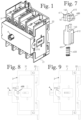
- Figure 1 shows an electrical switch
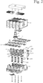
- Figure 2 shows an exploded view thereof.
- the electrical switch comprises a frame 2, an operating mechanism, a bridge assembly 6, a movable contact system, a stationary contact system, a neutral contact adjustment system 610, and a return spring system 300.
- the frame 2 comprises a first frame portion 21, and a second frame portion 22.
- a mechanism of the electrical switch is mounted in the frame 2.
- the movable contact system has four movable contacts comprising a movable neutral contact 131, and three movable phase contacts 132.
- the movable contacts are electrically insulated from each other.
- Each of the movable contacts is movable relative to the frame 2 between a connected position and a disconnected position such that the connected position corresponds to a connected state of the electrical switch, and the disconnected position corresponds to a disconnected state of the electrical switch.
- the stationary contact system has a stationary phase contact pair for each of the movable phase contacts 132, and a stationary neutral contact pair for the movable neutral contact 131.
- Each stationary phase contact pair and the stationary neutral contact pair comprises a first stationary contact 11 and a second stationary contact 12.
- the stationary contact system is stationary mounted relative to the frame 2.
- each stationary phase contact pair In the connected state of the electrical switch, each stationary phase contact pair is electrically conductively connected by a corresponding movable phase contact 132, and the stationary neutral contact pair is electrically conductively connected by the movable neutral contact 131. In the disconnected state of the electrical switch, each stationary phase contact pair is electrically isolated, and the stationary neutral contact pair is electrically isolated.
- the bridge assembly 6 comprises a bridge body 61, a neutral contact opening surface 631, and a phase contact opening surface 632 for each of the movable phase contacts 132.
- the bridge assembly 6 is movable in a depth direction relative to the frame 2 between a first bridge position and a second bridge position by means of the operating mechanism. In the connected state of the electrical switch, the bridge assembly 6 is in the first bridge position, and in the disconnected state of the electrical switch, the bridge assembly 6 is in the second bridge position.
- the bridge assembly 6 moves from the first bridge position to the second bridge position, the neutral contact opening surface 631 is in contact with the movable neutral contact 131 for moving the movable neutral contact 131 from the connected position to the disconnected position, and each phase contact opening surface 632 is in contact with a corresponding movable phase contact 132 for moving the movable phase contact 132 from the connected position to the disconnected position.
- the operating mechanism has a first operating position and a second operating position such that moving of the operating mechanism from the first operating position to the second operating position is adapted to provide the opening event.
- the operating mechanism comprises an operating shaft 4 rotatable relative to the frame 2 such that a first shaft position of the operating shaft 4 corresponds to the first operating position of the operating mechanism, and a second shaft position of the operating shaft 4 corresponds to the second operating position of the operating mechanism.
- a rotation axis of the operating shaft 4 is parallel with the depth direction.
- the operating shaft 4 is adapted to remain stationary in the depth direction during a rotation between the first shaft position and the second shaft position.
- the operating shaft 4 is adapted to exert a first opening force to the bridge assembly 6 for moving the bridge assembly 6 from the first bridge position to the second bridge position.
- the operating shaft 4 comprises a first screw thread surface 51
- the bridge body 61 comprises a second screw thread surface adapted to co-operate with the first screw thread surface 51 during the opening event such that said co-operation provides the first opening force.
- the bridge body 61 is made of electrically insulating material.
- the phase contact opening surfaces 632 are stationary relative to the bridge body 61.
- the phase contact opening surfaces 632 are integral parts of the bridge body 61.
- the neutral contact adjustment system 610 is adapted for adjusting a position of the neutral contact opening surface 631 relative to the phase contact opening surfaces 632. Therefore, the neutral contact adjustment system 610 is also adapted for adjusting a position of the neutral contact opening surface 631 relative to the bridge body 61.
- the neutral contact adjustment system 610 has a first operating state and a second operating state.
- the first operating state is adapted to provide a simultaneous break operation in which the movable neutral contact 131 disconnects simultaneously with the movable phase contacts 132 during the opening event.
- the second operating state is adapted to provide a late-break operation in which the movable neutral contact 131 disconnects later than the movable phase contacts 132 during the opening event.
- Figures 3A - 3C show a portion of the mechanism of the electrical switch shown in Figure 1 from different directions, in a situation where the neutral contact adjustment system 610 is in the first operating state.
- Figure 4 shows the portion of the mechanism shown in Figure 3C in cross section.
- Figures 5A - 5C show the portion of the mechanism of the electrical switch shown in Figure 1 from different directions, in a situation where the neutral contact adjustment system 610 is in the second operating state.
- Figure 6 shows the portion of the mechanism shown in Figure 5C in cross section.
- Figure 7 shows an enlargement of the neutral contact adjustment system 610.
- the neutral contact adjustment system 610 comprises a first adjustment member 611, a second adjustment member 612, and a retaining spring 633.
- the first adjustment member 611 and the second adjustment member 612 are made of electrically insulating material.
- the retaining spring 633 is a coil spring.
- the first adjustment member 611 is rotatable relative to the bridge body 61 between a simultaneous break position and a late-break position.
- An angle between the simultaneous break position and the late-break position is 90°.
- the second adjustment member 612 comprises the neutral contact opening surface 631, and is movable in the depth direction relative to the bridge body 61 between a simultaneous break location and a late-break location by rotation of the first adjustment member 611 between the simultaneous break position and the late-break position.
- the neutral contact opening surface 631 is an integral part of the second adjustment member 612.
- the first adjustment member 611 is an eccentric member comprising a first contact surface 161 and a second contact surface 162 such that a distance between a rotation axis of the first adjustment member 611 and the first contact surface 161 is greater than a distance between the rotation axis of the first adjustment member 611 and the second contact surface 162.
- the rotation axis of the first adjustment member 611 is stationary relative to the bridge body 61 such that the first adjustment member 611 is only adapted to rotate relative to the bridge body 61.
- the second adjustment member 612 comprises a counter surface 163 such that in the simultaneous break position of the first adjustment member the counter surface 163 is in contact with the first contact surface 161, and in the late-break position of the first adjustment member the counter surface 163 is in contact with the second contact surface 162.
- the counter surface 163 is an integral part of the second adjustment member 612.
- the first contact surface 161 and the second contact surface 162 are shaped as recesses, and the counter surface 163 is shaped as a protrusion.
- the first adjustment member 611 comprises two first contact surfaces 161, and two second contact surfaces 162 such that a cross-section of the first adjustment member 611 on a plane perpendicular to the rotation axis thereof resembles slightly a butterfly or a four-leaved clover.
- the retaining spring 633 exerts a first spring force to the bridge body 61 and a second spring force to the second adjustment member 612.
- the second spring force is pressing the second adjustment member 612 against the first adjustment member 611 in order to resist movement of the first adjustment member 611 between the simultaneous break position and the late-break position.
- the first adjustment member 611 and the second adjustment member 612 are shaped such that the first adjustment member 611 has an intermediate position between the simultaneous break position and the late-break position such that in the intermediate position of the first adjustment member 611, the retaining spring 633 presses the second adjustment member 612 stronger against the first adjustment member 611 than in the simultaneous break position and in the late-break position. Therefore, the shapes of the first adjustment member 611 and the second adjustment member 612 are adapted to resist movement of the first adjustment member 611 between the simultaneous break position and the late-break position such that the first adjustment member 611 is not able to rotate from the simultaneous break position to the late-break position or from the late-break position to the simultaneous break position without an external force applied to the first adjustment member 611.
- the first adjustment member 611 comprises an operating head 688 adapted for rotating the first adjustment member 611 between the simultaneous break position and the late-break position.
- the operating head 688 is adapted to be rotated with a screwdriver.
- Figure 8 shows a side view of the electrical switch in the connected state
- Figure 9 shows a side view of the electrical switch in the disconnected state
- the depth direction is a horizontal direction
- Figures 8 and 9 show that the frame 2 is provided with an adjustment aperture 210 such that in the connected state of the electrical switch, the operating head 688 is accessible through the adjustment aperture 210, and in the disconnected state of the electrical switch the frame 2 blocks access to the operating head 688.
- the operating head 688 is accessible in the first bridge position, and inaccessible in the second bridge position.
- the first adjustment member 611 is adapted to provide a visible position indication indicating whether the first adjustment member 611 is in the simultaneous break position or the late-break position.
- the operating head 688 has a slot head adapted to be driven by a flat-bladed screwdriver, and therefore a direction of the slot head indicates whether the first adjustment member 611 is in the simultaneous break position or in the late-break position.
- the return spring system 300 is adapted to exert return forces to the movable contact system in order to return the movable neutral contact 131 and the movable phase contacts 132 to their connected positions if they are deflected therefrom in the direction of the disconnected positions thereof.
- the return spring system 300 comprises four return springs 301, 302, 303 and 304. Each of the return springs 301, 302 and 303 is in contact with a corresponding movable phase contact 132.
- the return spring 304 is in contact with the movable neutral contact 131.
- the first stationary contacts 11 and the second stationary contacts 12 of the electrical switch are located on the same plane.
- the movable neutral contact 131 and the movable phase contacts 132 are in contact with the first stationary contacts 11 and the second stationary contacts 12 such that there is a small gap between the neutral contact opening surface 631 and the movable neutral contact 131, and between each phase contact opening surface 632 and a corresponding movable phase contact 132.
- an operating state of the neutral contact adjustment system 610 affects a size of a gap between the neutral contact opening surface 631 and the movable neutral contact 131.
- said gap is greater than in the first operating state. It is the larger gap that provides the late-break operation.
- the neutral contact opening surface 631 is in contact with the movable neutral contact 131, and each phase contact opening surface 632 is in contact with a corresponding movable phase contact 132 regardless of the operating state of the neutral contact adjustment system 610.
Landscapes
- Engineering & Computer Science (AREA)
- Power Engineering (AREA)
- Physics & Mathematics (AREA)
- Electromagnetism (AREA)
- Rotary Switch, Piano Key Switch, And Lever Switch (AREA)
Claims (15)
- Elektrischer Schalter, der Folgendes umfasst:einen Rahmen (2);ein System beweglicher Kontakte, das mehrere bewegliche Kontakte aufweist, die einen beweglichen Neutralkontakt (131) und mindestens einen beweglichen Phasenkontakt (132) umfassen, wobei jeder der beweglichen Kontakte in Bezug auf den Rahmen (2) zwischen einer verbundenen Position und einer getrennten Position beweglich ist;eine Brückenanordnung (6), die einen Brückenkörper (61), eine Neutralkontakt-Öffnungsfläche (631) und eine Phasenkontakt-Öffnungsfläche (632) für jeden des mindestens einen beweglichen Phasenkontakts (132) umfasst, wobei die Brückenanordnung (6) in einer Tiefenrichtung in Bezug auf den Rahmen (2) zwischen einer ersten Brückenposition und einer zweiten Brückenposition beweglich ist,wobei sich die Brückenanordnung (6) während eines Öffnungsereignisses, bei dem der elektrische Schalter aus einem verbundenen Zustand in einen getrennten Zustand übergeht, aus der ersten Brückenposition in die zweite Brückenposition bewegt, die Neutralkontakt-Öffnungsfläche (631) sich zum Bewegen des beweglichen Neutralkontakts (131) aus der verbundenen Position in die getrennte Position mit dem beweglichen Neutralkontakt (131) in Kontakt befindet und jede Phasenkontakt-Öffnungsfläche (632) sich zum Bewegen des beweglichen Phasenkontakts (132) aus der verbundenen Position in die getrennte Position mit einem entsprechenden beweglichen Phasenkontakt (132) in Kontakt befindet,dadurch gekennzeichnet, dass der elektrische Schalter ein Neutralkontakt-Einstellsystem (610) umfasst, das zum Einstellen einer Position der Neutralkontakt-Öffnungsfläche (631) in Bezug auf die mindestens eine Phasenkontakt-Öffnungsfläche (632) derart ausgelegt ist, dass das Neutralkontakt-Einstellsystem (610) einen ersten Betriebszustand, der ausgelegt ist, einen gleichzeitigen Öffnungsvorgang, bei dem der bewegliche Neutralkontakt (131) während des Öffnungsereignisses gleichzeitig mit dem mindestens einen beweglichen Phasenkontakt (132) trennt, bereitzustellen, und einen zweiten Betriebszustand, der ausgelegt ist, einen nacheilenden Öffnungsvorgang, bei dem der bewegliche Neutralkontakt (131) während des Öffnungsereignisses später als der mindestens eine bewegliche Phasenkontakt (132) trennt, bereitzustellen, aufweist.
- Elektrischer Schalter nach Anspruch 1, wobei das Neutralkontakt-Einstellsystem (610) Folgendes umfasst:ein erstes Einstellelement (611), das in Bezug auf den Brückenkörper (61) zwischen einer Position zum gleichzeitigen Öffnen und einer Position zum nacheilenden Öffnen drehbar ist; undein zweites Einstellelement (612), das die Neutralkontakt-Öffnungsfläche (631) umfasst und durch Drehung des ersten Einstellelements (611) zwischen der Position zum gleichzeitigen Öffnen und der Position zum nacheilenden Öffnen in Bezug auf den Brückenkörper (61) in der Tiefenrichtung zwischen einem Ort zum gleichzeitigen Öffnen und einem Ort zum nacheilenden Öffnen beweglich ist.
- Elektrischer Schalter nach Anspruch 2, wobei das erste Einstellelement (611) ein dezentriertes Element ist, das eine erste Kontaktfläche (161) und eine zweite Kontaktfläche (162) umfasst, derart, dass ein Abstand zwischen einer Drehachse des ersten Einstellelements (611) und der ersten Kontaktfläche (161) größer als ein Abstand zwischen der Drehachse des ersten Einstellelements (611) und der zweiten Kontaktfläche (162) ist, und das zweite Einstellelement (612) eine Gegenfläche (163) umfasst, derart, dass sich die Gegenfläche (163) in der Position zum gleichzeitigen Öffnen des ersten Einstellelements mit der ersten Kontaktfläche (161) in Kontakt befindet und die Gegenkontaktfläche (163) sich in der Position zum nacheilenden Öffnen des ersten Einstellelements mit der zweiten Kontaktfläche (162) in Kontakt befindet.
- Elektrischer Schalter nach Anspruch 2 oder 3, wobei das Neutralkontakt-Einstellsystem (610) eine Haltefeder (633) umfasst, die eine erste Federkraft auf den Brückenkörper (61) und eine zweite Federkraft auf das zweite Einstellelement (612) ausübt, wobei die zweite Federkraft das zweite Einstellelement (612) gegen das erste Einstellelement (611) drückt, um einer Bewegung des ersten Einstellelements (611) zwischen der Position zum gleichzeitigen Öffnen und der Position zum nacheilenden Öffnen zu widerstehen.
- Elektrischer Schalter nach Anspruch 4, wobei das erste Einstellelement (611) und das zweite Einstellelement (612) derart geformt sind, dass das erste Einstellelement (611) eine Zwischenposition zwischen der Position zum gleichzeitigen Öffnen und der Position zum nacheilenden Öffnen aufweist, derart, dass die Haltefeder (633) in der Zwischenposition des ersten Einstellelements (611) das zweite Einstellelement (612) stärker gegen das erste Einstellelement (611) drückt als in der Position zum gleichzeitigen Öffnen und in der Position zum nacheilenden Öffnen.
- Elektrischer Schalter nach Anspruch 5, wobei die erste Kontaktfläche (161) und die zweite Kontaktfläche (162) als Vertiefungen geformt sind und die Gegenfläche (163) als ein Vorsprung geformt ist.
- Elektrischer Schalter nach einem der Ansprüche 2 bis 6, wobei ein Winkel zwischen der Position zum gleichzeitigen Öffnen und der Position zum nacheilenden Öffnen 90° ist.
- Elektrischer Schalter nach einem der Ansprüche 2 bis 6, wobei das erste Einstellelement (611) einen Betätigungskopf (688) umfasst, der zum Drehen des ersten Einstellelements (611) zwischen der Position zum gleichzeitigen Öffnen und der Position zum nacheilenden Öffnen ausgelegt ist, wobei auf den Betätigungskopf (688) in der ersten Brückenposition zugegriffen werden kann und in der zweiten Brückenposition nicht zugegriffen werden kann.
- Elektrischer Schalter nach Anspruch 8, wobei der Rahmen (2) mit einer Einstellöffnung (210) versehen ist, derart, dass auf den Betätigungskopf (688) in der ersten Brückenposition durch die Einstellöffnung (210) zugegriffen werden kann und in der zweiten Brückenposition der Rahmen (2) den Zugriff auf den Betätigungskopf (688) sperrt.
- Elektrischer Schalter nach Anspruch 9, wobei das erste Einstellelement (611) in der ersten Brückenposition ausgelegt ist, eine sichtbare Positionsanzeige bereitzustellen, die anzeigt, ob sich das erste Einstellelement (611) in der Position zum gleichzeitigen Öffnen oder der Position zum nacheilenden Öffnen befindet.
- Elektrischer Schalter nach einem der vorhergehenden Ansprüche, wobei der elektrische Schalter einen Betätigungsmechanismus umfasst, der eine erste Betätigungsposition und eine zweite Betätigungsposition aufweist, derart, dass das Bewegen des Betätigungsmechanismus aus der ersten Betätigungsposition in die zweite Betätigungsposition ausgelegt ist, das Öffnungsereignis bereitzustellen.
- Elektrischer Schalter nach Anspruch 11, wobei der Betätigungsmechanismus eine Betätigungswelle (4) umfasst, die in Bezug auf den Rahmen (2) drehbar ist, derart, dass eine erste Wellenposition der Betätigungswelle (4) der ersten Betätigungsposition entspricht und eine zweite Wellenposition der Betätigungswelle (4) der zweiten Betätigungsposition entspricht, wobei die Betätigungswelle (4) ausgelegt ist, während des Öffnungsereignisses eine erste Öffnungskraft auf die Brückenanordnung (6) auszuüben.
- Elektrischer Schalter nach Anspruch 12, wobei die Betätigungswelle (4) eine erste Schraubengewindefläche (51) umfasst und die Brückenanordnung (6) eine zweite Schraubengewindefläche umfasst, die ausgelegt ist, während des Öffnungsereignisses mit der ersten Schraubengewindefläche (51) zusammenzuwirken, derart, dass das Zusammenwirken die erste Öffnungskraft bereitstellt, wobei die Tiefenrichtung zu einer Drehachse der Betätigungswelle (4) parallel ist und die Betätigungswelle (4) ausgelegt ist, während einer Drehung zwischen der ersten Wellenposition und der zweiten Wellenposition in der Tiefenrichtung feststehend zu bleiben.
- Elektrischer Schalter nach einem der vorhergehenden Ansprüche, wobei der elektrische Schalter ein Rückstellfedersystem (300) umfasst, das ausgelegt ist, Rückstellkräfte auf das bewegliche Kontaktsystem auszuüben, um den beweglichen Neutralkontakt (131) und den mindestens einen beweglichen Phasenkontakt (132) in ihre verbundenen Positionen zurückzustellen, wenn sie in der Richtung ihrer getrennten Positionen daraus ausgelenkt sind.
- Elektrischer Schalter nach einem der vorhergehenden Ansprüche, wobei der elektrische Schalter ein feststehendes Kontaktsystem umfasst, das ein feststehendes Phasenkontaktpaar für jeden des mindestens einen beweglichen Phasenkontakts (132) und ein feststehendes Neutralkontaktpaar für den beweglichen Neutralkontakt (131) aufweist, wobei das feststehende Kontaktsystem in Bezug auf den Rahmen (2) feststehend angebracht ist, wobei im verbundenen Zustand jedes feststehende Phasenkontaktpaar durch einen entsprechenden beweglichen Phasenkontakt (132) elektrisch leitfähig verbunden ist und das feststehende Neutralkontaktpaar durch den beweglichen Neutralkontakt (131) elektrisch leitfähig verbunden ist und im getrennten Zustand jedes feststehende Phasenkontaktpaar elektrisch isoliert ist und das feststehende Neutralkontaktpaar elektrisch isoliert ist.
Priority Applications (3)
| Application Number | Priority Date | Filing Date | Title |
|---|---|---|---|
| EP21177117.5A EP4099355B1 (de) | 2021-06-01 | 2021-06-01 | Elektrischer schalter |
| US17/804,489 US11776768B2 (en) | 2021-06-01 | 2022-05-27 | Electrical switch |
| CN202210601712.3A CN115440517B (zh) | 2021-06-01 | 2022-05-30 | 电气开关 |
Applications Claiming Priority (1)
| Application Number | Priority Date | Filing Date | Title |
|---|---|---|---|
| EP21177117.5A EP4099355B1 (de) | 2021-06-01 | 2021-06-01 | Elektrischer schalter |
Publications (2)
| Publication Number | Publication Date |
|---|---|
| EP4099355A1 EP4099355A1 (de) | 2022-12-07 |
| EP4099355B1 true EP4099355B1 (de) | 2025-04-30 |
Family
ID=76250069
Family Applications (1)
| Application Number | Title | Priority Date | Filing Date |
|---|---|---|---|
| EP21177117.5A Active EP4099355B1 (de) | 2021-06-01 | 2021-06-01 | Elektrischer schalter |
Country Status (3)
| Country | Link |
|---|---|
| US (1) | US11776768B2 (de) |
| EP (1) | EP4099355B1 (de) |
| CN (1) | CN115440517B (de) |
Families Citing this family (1)
| Publication number | Priority date | Publication date | Assignee | Title |
|---|---|---|---|---|
| EP4099354B1 (de) * | 2021-06-01 | 2025-04-16 | ABB Schweiz AG | Elektrischer schalter |
Family Cites Families (12)
| Publication number | Priority date | Publication date | Assignee | Title |
|---|---|---|---|---|
| DE1690801U (de) * | 1954-10-07 | 1955-01-05 | Stotz Kontakt Gmbh | Niederspannungsschalter, insbesondere motorschutzschalter. |
| DE1813181U (de) * | 1957-06-28 | 1960-06-15 | Naimer H L | Elektrisches schaltgeraet zur verwendung in dreiphasenwechselstromsystemen. |
| JPS58212025A (ja) * | 1982-06-03 | 1983-12-09 | 株式会社市右衛門商社 | 接触器 |
| FR2802017B1 (fr) * | 1999-12-03 | 2004-05-14 | Schneider Electric Ind Sa | Appareillage de coupure triphase de forte intensite a deux poles jumeles par phase, muni de circuits magnetiques de compensation |
| JP4933208B2 (ja) * | 2006-09-29 | 2012-05-16 | 河村電器産業株式会社 | 回路遮断器 |
| CN103700519B (zh) * | 2013-12-25 | 2015-11-18 | 施耐德万高(天津)电气设备有限公司 | 一种具有中性极重叠切换功能的自动转换开关电器 |
| CN203659647U (zh) * | 2013-12-25 | 2014-06-18 | 施耐德万高(天津)电气设备有限公司 | 一种具有中性极重叠切换功能的自动转换开关电器 |
| US20170178847A1 (en) * | 2015-12-21 | 2017-06-22 | Schneider Eletric Usa, Inc. | Arc energy reduction method and apparatus for multi-phase switching devices |
| FR3093857B1 (fr) * | 2019-03-14 | 2021-02-19 | Schneider Electric Ind Sas | Appareil electrique destine a etablir ou interrompre le courant dans un circuit electrique. |
| CN112017880B (zh) * | 2019-05-30 | 2024-10-22 | 上海良信电器股份有限公司 | 一种中性线重叠时间可调的自动转换开关 |
| FI129415B (en) * | 2019-06-20 | 2022-02-15 | Abb Schweiz Ag | Switches |
| CN210429687U (zh) * | 2019-11-19 | 2020-04-28 | 常安集团有限公司 | 一种交流接触器 |
-
2021
- 2021-06-01 EP EP21177117.5A patent/EP4099355B1/de active Active
-
2022
- 2022-05-27 US US17/804,489 patent/US11776768B2/en active Active
- 2022-05-30 CN CN202210601712.3A patent/CN115440517B/zh active Active
Also Published As
| Publication number | Publication date |
|---|---|
| US20220384120A1 (en) | 2022-12-01 |
| US11776768B2 (en) | 2023-10-03 |
| EP4099355A1 (de) | 2022-12-07 |
| CN115440517B (zh) | 2025-09-16 |
| CN115440517A (zh) | 2022-12-06 |
Similar Documents
| Publication | Publication Date | Title |
|---|---|---|
| EP2037475B1 (de) | Betriebsmechanismus mit Einstellung der Kontaktkraft | |
| EP4099355B1 (de) | Elektrischer schalter | |
| US3275764A (en) | Electric limit switch having a diagonally divided housing, a detachable actuator, and mechanisms for causing selected operation of a push button snap switch | |
| US10395864B2 (en) | Switching device comprising a resetting device | |
| EP3916745B1 (de) | Elektrischer schalter | |
| US4712079A (en) | Motor controller auxiliary contact unit with flexure member | |
| TWM565390U (zh) | 開關裝置改良結構 | |
| EP4099354B1 (de) | Elektrischer schalter | |
| KR20050113593A (ko) | 시퀀스 스위치용 부하시 탭 절환장치 | |
| US6239395B1 (en) | Auxiliary position switch assembly for a circuit breaker | |
| US6759932B2 (en) | Magnetic sensor switch | |
| EP4050636B1 (de) | Steuerungsmodul, steuerungsmodulanordnung und elektrischer schalter mit der steuerungsmodulanordnung | |
| EP3776616B1 (de) | Federbelastetes hilfskontaktsystem für busübertragungsschaltung in einem drehtrennschalter | |
| US991661A (en) | Contact-finger. | |
| US20130192969A1 (en) | Switching apparatus for a low-voltage electrical switching device | |
| CN223566455U (zh) | 开关装置 | |
| CN215770982U (zh) | 辅助开关装置及具有其的断路器 | |
| EP3133627B1 (de) | Mehrpolige schalteranordnung mit einstellbarer gleichzeitigkeit | |
| JP2010251079A (ja) | 開閉器 | |
| JPS634517A (ja) | 電気スイッチ | |
| CN101512696B (zh) | 具有可绕第一旋转轴旋转的第一传递元件的传动单元尤其是操作头 | |
| CN101136292A (zh) | 开关装置 | |
| KR100293425B1 (ko) | 제어 회로용 캠스위치 | |
| KR20170077659A (ko) | 기중차단기의 접점 구조 | |
| KR20240144400A (ko) | 콘택트 어셈블리 |
Legal Events
| Date | Code | Title | Description |
|---|---|---|---|
| PUAI | Public reference made under article 153(3) epc to a published international application that has entered the european phase |
Free format text: ORIGINAL CODE: 0009012 |
|
| STAA | Information on the status of an ep patent application or granted ep patent |
Free format text: STATUS: THE APPLICATION HAS BEEN PUBLISHED |
|
| AK | Designated contracting states |
Kind code of ref document: A1 Designated state(s): AL AT BE BG CH CY CZ DE DK EE ES FI FR GB GR HR HU IE IS IT LI LT LU LV MC MK MT NL NO PL PT RO RS SE SI SK SM TR |
|
| STAA | Information on the status of an ep patent application or granted ep patent |
Free format text: STATUS: REQUEST FOR EXAMINATION WAS MADE |
|
| 17P | Request for examination filed |
Effective date: 20230110 |
|
| RBV | Designated contracting states (corrected) |
Designated state(s): AL AT BE BG CH CY CZ DE DK EE ES FI FR GB GR HR HU IE IS IT LI LT LU LV MC MK MT NL NO PL PT RO RS SE SI SK SM TR |
|
| GRAP | Despatch of communication of intention to grant a patent |
Free format text: ORIGINAL CODE: EPIDOSNIGR1 |
|
| STAA | Information on the status of an ep patent application or granted ep patent |
Free format text: STATUS: GRANT OF PATENT IS INTENDED |
|
| INTG | Intention to grant announced |
Effective date: 20241220 |
|
| GRAS | Grant fee paid |
Free format text: ORIGINAL CODE: EPIDOSNIGR3 |
|
| GRAA | (expected) grant |
Free format text: ORIGINAL CODE: 0009210 |
|
| STAA | Information on the status of an ep patent application or granted ep patent |
Free format text: STATUS: THE PATENT HAS BEEN GRANTED |
|
| AK | Designated contracting states |
Kind code of ref document: B1 Designated state(s): AL AT BE BG CH CY CZ DE DK EE ES FI FR GB GR HR HU IE IS IT LI LT LU LV MC MK MT NL NO PL PT RO RS SE SI SK SM TR |
|
| REG | Reference to a national code |
Ref country code: CH Ref legal event code: EP Ref country code: GB Ref legal event code: FG4D |
|
| REG | Reference to a national code |
Ref country code: DE Ref legal event code: R096 Ref document number: 602021029878 Country of ref document: DE |
|
| REG | Reference to a national code |
Ref country code: IE Ref legal event code: FG4D |
|
| PGFP | Annual fee paid to national office [announced via postgrant information from national office to epo] |
Ref country code: DE Payment date: 20250618 Year of fee payment: 5 |
|
| PGFP | Annual fee paid to national office [announced via postgrant information from national office to epo] |
Ref country code: GB Payment date: 20250618 Year of fee payment: 5 |
|
| PGFP | Annual fee paid to national office [announced via postgrant information from national office to epo] |
Ref country code: FR Payment date: 20250627 Year of fee payment: 5 |
|
| PGFP | Annual fee paid to national office [announced via postgrant information from national office to epo] |
Ref country code: AT Payment date: 20250721 Year of fee payment: 5 |
|
| REG | Reference to a national code |
Ref country code: NL Ref legal event code: MP Effective date: 20250430 |
|
| REG | Reference to a national code |
Ref country code: AT Ref legal event code: MK05 Ref document number: 1790874 Country of ref document: AT Kind code of ref document: T Effective date: 20250430 |
|
| PG25 | Lapsed in a contracting state [announced via postgrant information from national office to epo] |
Ref country code: PT Free format text: LAPSE BECAUSE OF FAILURE TO SUBMIT A TRANSLATION OF THE DESCRIPTION OR TO PAY THE FEE WITHIN THE PRESCRIBED TIME-LIMIT Effective date: 20250901 Ref country code: ES Free format text: LAPSE BECAUSE OF FAILURE TO SUBMIT A TRANSLATION OF THE DESCRIPTION OR TO PAY THE FEE WITHIN THE PRESCRIBED TIME-LIMIT Effective date: 20250430 Ref country code: FI Free format text: LAPSE BECAUSE OF FAILURE TO SUBMIT A TRANSLATION OF THE DESCRIPTION OR TO PAY THE FEE WITHIN THE PRESCRIBED TIME-LIMIT Effective date: 20250430 |
|
| REG | Reference to a national code |
Ref country code: LT Ref legal event code: MG9D |
|
| PG25 | Lapsed in a contracting state [announced via postgrant information from national office to epo] |
Ref country code: GR Free format text: LAPSE BECAUSE OF FAILURE TO SUBMIT A TRANSLATION OF THE DESCRIPTION OR TO PAY THE FEE WITHIN THE PRESCRIBED TIME-LIMIT Effective date: 20250731 Ref country code: NO Free format text: LAPSE BECAUSE OF FAILURE TO SUBMIT A TRANSLATION OF THE DESCRIPTION OR TO PAY THE FEE WITHIN THE PRESCRIBED TIME-LIMIT Effective date: 20250730 |
|
| PG25 | Lapsed in a contracting state [announced via postgrant information from national office to epo] |
Ref country code: PL Free format text: LAPSE BECAUSE OF FAILURE TO SUBMIT A TRANSLATION OF THE DESCRIPTION OR TO PAY THE FEE WITHIN THE PRESCRIBED TIME-LIMIT Effective date: 20250430 Ref country code: NL Free format text: LAPSE BECAUSE OF FAILURE TO SUBMIT A TRANSLATION OF THE DESCRIPTION OR TO PAY THE FEE WITHIN THE PRESCRIBED TIME-LIMIT Effective date: 20250430 |
|
| PGFP | Annual fee paid to national office [announced via postgrant information from national office to epo] |
Ref country code: IT Payment date: 20250730 Year of fee payment: 5 |
|
| PG25 | Lapsed in a contracting state [announced via postgrant information from national office to epo] |
Ref country code: BG Free format text: LAPSE BECAUSE OF FAILURE TO SUBMIT A TRANSLATION OF THE DESCRIPTION OR TO PAY THE FEE WITHIN THE PRESCRIBED TIME-LIMIT Effective date: 20250430 |
|
| PG25 | Lapsed in a contracting state [announced via postgrant information from national office to epo] |
Ref country code: HR Free format text: LAPSE BECAUSE OF FAILURE TO SUBMIT A TRANSLATION OF THE DESCRIPTION OR TO PAY THE FEE WITHIN THE PRESCRIBED TIME-LIMIT Effective date: 20250430 |
|
| PG25 | Lapsed in a contracting state [announced via postgrant information from national office to epo] |
Ref country code: AT Free format text: LAPSE BECAUSE OF FAILURE TO SUBMIT A TRANSLATION OF THE DESCRIPTION OR TO PAY THE FEE WITHIN THE PRESCRIBED TIME-LIMIT Effective date: 20250430 |
|
| PG25 | Lapsed in a contracting state [announced via postgrant information from national office to epo] |
Ref country code: RS Free format text: LAPSE BECAUSE OF FAILURE TO SUBMIT A TRANSLATION OF THE DESCRIPTION OR TO PAY THE FEE WITHIN THE PRESCRIBED TIME-LIMIT Effective date: 20250731 |
|
| PG25 | Lapsed in a contracting state [announced via postgrant information from national office to epo] |
Ref country code: IS Free format text: LAPSE BECAUSE OF FAILURE TO SUBMIT A TRANSLATION OF THE DESCRIPTION OR TO PAY THE FEE WITHIN THE PRESCRIBED TIME-LIMIT Effective date: 20250830 |
|
| PG25 | Lapsed in a contracting state [announced via postgrant information from national office to epo] |
Ref country code: LV Free format text: LAPSE BECAUSE OF FAILURE TO SUBMIT A TRANSLATION OF THE DESCRIPTION OR TO PAY THE FEE WITHIN THE PRESCRIBED TIME-LIMIT Effective date: 20250430 |