EP4099117A1 - Hilfsverfahren zum steuern eines drehflügelflugzeugs, das mindestens zwei motoren umfasst - Google Patents
Hilfsverfahren zum steuern eines drehflügelflugzeugs, das mindestens zwei motoren umfasst Download PDFInfo
- Publication number
- EP4099117A1 EP4099117A1 EP22170920.7A EP22170920A EP4099117A1 EP 4099117 A1 EP4099117 A1 EP 4099117A1 EP 22170920 A EP22170920 A EP 22170920A EP 4099117 A1 EP4099117 A1 EP 4099117A1
- Authority
- EP
- European Patent Office
- Prior art keywords
- rotorcraft
- periodic
- descent
- current position
- current
- Prior art date
- Legal status (The legal status is an assumption and is not a legal conclusion. Google has not performed a legal analysis and makes no representation as to the accuracy of the status listed.)
- Granted
Links
- 238000000034 method Methods 0.000 title claims abstract description 64
- 230000000737 periodic effect Effects 0.000 claims abstract description 54
- 230000006870 function Effects 0.000 claims description 22
- 230000001133 acceleration Effects 0.000 claims description 13
- 230000015556 catabolic process Effects 0.000 claims description 3
- 230000003247 decreasing effect Effects 0.000 claims description 3
- 238000012545 processing Methods 0.000 description 9
- RZVHIXYEVGDQDX-UHFFFAOYSA-N 9,10-anthraquinone Chemical compound C1=CC=C2C(=O)C3=CC=CC=C3C(=O)C2=C1 RZVHIXYEVGDQDX-UHFFFAOYSA-N 0.000 description 5
- 230000007423 decrease Effects 0.000 description 3
- 238000013459 approach Methods 0.000 description 2
- 230000014509 gene expression Effects 0.000 description 2
- 239000003550 marker Substances 0.000 description 2
- 238000005259 measurement Methods 0.000 description 2
- 210000000056 organ Anatomy 0.000 description 2
- 230000004913 activation Effects 0.000 description 1
- 230000008859 change Effects 0.000 description 1
- 125000004122 cyclic group Chemical group 0.000 description 1
- 238000010586 diagram Methods 0.000 description 1
- 230000000694 effects Effects 0.000 description 1
- 230000004048 modification Effects 0.000 description 1
- 238000012986 modification Methods 0.000 description 1
- 238000012544 monitoring process Methods 0.000 description 1
- 230000009467 reduction Effects 0.000 description 1
- 230000000007 visual effect Effects 0.000 description 1
Images


Classifications
-
- B—PERFORMING OPERATIONS; TRANSPORTING
- B64—AIRCRAFT; AVIATION; COSMONAUTICS
- B64C—AEROPLANES; HELICOPTERS
- B64C27/00—Rotorcraft; Rotors peculiar thereto
- B64C27/54—Mechanisms for controlling blade adjustment or movement relative to rotor head, e.g. lag-lead movement
- B64C27/56—Mechanisms for controlling blade adjustment or movement relative to rotor head, e.g. lag-lead movement characterised by the control initiating means, e.g. manually actuated
- B64C27/57—Mechanisms for controlling blade adjustment or movement relative to rotor head, e.g. lag-lead movement characterised by the control initiating means, e.g. manually actuated automatic or condition responsive, e.g. responsive to rotor speed, torque or thrust
-
- G—PHYSICS
- G05—CONTROLLING; REGULATING
- G05D—SYSTEMS FOR CONTROLLING OR REGULATING NON-ELECTRIC VARIABLES
- G05D1/00—Control of position, course or altitude of land, water, air, or space vehicles, e.g. automatic pilot
- G05D1/0055—Control of position, course or altitude of land, water, air, or space vehicles, e.g. automatic pilot with safety arrangements
- G05D1/0072—Control of position, course or altitude of land, water, air, or space vehicles, e.g. automatic pilot with safety arrangements to counteract a motor failure
-
- B—PERFORMING OPERATIONS; TRANSPORTING
- B64—AIRCRAFT; AVIATION; COSMONAUTICS
- B64C—AEROPLANES; HELICOPTERS
- B64C13/00—Control systems or transmitting systems for actuating flying-control surfaces, lift-increasing flaps, air brakes, or spoilers
- B64C13/02—Initiating means
-
- B—PERFORMING OPERATIONS; TRANSPORTING
- B64—AIRCRAFT; AVIATION; COSMONAUTICS
- B64C—AEROPLANES; HELICOPTERS
- B64C13/00—Control systems or transmitting systems for actuating flying-control surfaces, lift-increasing flaps, air brakes, or spoilers
- B64C13/02—Initiating means
- B64C13/16—Initiating means actuated automatically, e.g. responsive to gust detectors
- B64C13/18—Initiating means actuated automatically, e.g. responsive to gust detectors using automatic pilot
-
- B—PERFORMING OPERATIONS; TRANSPORTING
- B64—AIRCRAFT; AVIATION; COSMONAUTICS
- B64C—AEROPLANES; HELICOPTERS
- B64C1/00—Fuselages; Constructional features common to fuselages, wings, stabilising surfaces or the like
- B64C1/0009—Aerodynamic aspects
-
- B—PERFORMING OPERATIONS; TRANSPORTING
- B64—AIRCRAFT; AVIATION; COSMONAUTICS
- B64C—AEROPLANES; HELICOPTERS
- B64C13/00—Control systems or transmitting systems for actuating flying-control surfaces, lift-increasing flaps, air brakes, or spoilers
- B64C13/02—Initiating means
- B64C13/16—Initiating means actuated automatically, e.g. responsive to gust detectors
- B64C13/22—Initiating means actuated automatically, e.g. responsive to gust detectors readily revertible to personal control
-
- B—PERFORMING OPERATIONS; TRANSPORTING
- B64—AIRCRAFT; AVIATION; COSMONAUTICS
- B64C—AEROPLANES; HELICOPTERS
- B64C27/00—Rotorcraft; Rotors peculiar thereto
- B64C27/006—Safety devices
-
- B—PERFORMING OPERATIONS; TRANSPORTING
- B64—AIRCRAFT; AVIATION; COSMONAUTICS
- B64D—EQUIPMENT FOR FITTING IN OR TO AIRCRAFT; FLIGHT SUITS; PARACHUTES; ARRANGEMENTS OR MOUNTING OF POWER PLANTS OR PROPULSION TRANSMISSIONS IN AIRCRAFT
- B64D35/00—Transmitting power from power plant to propellers or rotors; Arrangements of transmissions
- B64D35/08—Transmitting power from power plant to propellers or rotors; Arrangements of transmissions characterised by the transmission being driven by a plurality of power plants
-
- B—PERFORMING OPERATIONS; TRANSPORTING
- B64—AIRCRAFT; AVIATION; COSMONAUTICS
- B64D—EQUIPMENT FOR FITTING IN OR TO AIRCRAFT; FLIGHT SUITS; PARACHUTES; ARRANGEMENTS OR MOUNTING OF POWER PLANTS OR PROPULSION TRANSMISSIONS IN AIRCRAFT
- B64D43/00—Arrangements or adaptations of instruments
-
- B—PERFORMING OPERATIONS; TRANSPORTING
- B64—AIRCRAFT; AVIATION; COSMONAUTICS
- B64D—EQUIPMENT FOR FITTING IN OR TO AIRCRAFT; FLIGHT SUITS; PARACHUTES; ARRANGEMENTS OR MOUNTING OF POWER PLANTS OR PROPULSION TRANSMISSIONS IN AIRCRAFT
- B64D45/00—Aircraft indicators or protectors not otherwise provided for
- B64D45/04—Landing aids; Safety measures to prevent collision with earth's surface
- B64D45/08—Landing aids; Safety measures to prevent collision with earth's surface optical
-
- G—PHYSICS
- G05—CONTROLLING; REGULATING
- G05D—SYSTEMS FOR CONTROLLING OR REGULATING NON-ELECTRIC VARIABLES
- G05D1/00—Control of position, course or altitude of land, water, air, or space vehicles, e.g. automatic pilot
- G05D1/04—Control of altitude or depth
- G05D1/06—Rate of change of altitude or depth
- G05D1/0607—Rate of change of altitude or depth specially adapted for aircraft
- G05D1/0653—Rate of change of altitude or depth specially adapted for aircraft during a phase of take-off or landing
- G05D1/0676—Rate of change of altitude or depth specially adapted for aircraft during a phase of take-off or landing specially adapted for landing
-
- G—PHYSICS
- G05—CONTROLLING; REGULATING
- G05D—SYSTEMS FOR CONTROLLING OR REGULATING NON-ELECTRIC VARIABLES
- G05D1/00—Control of position, course or altitude of land, water, air, or space vehicles, e.g. automatic pilot
- G05D1/04—Control of altitude or depth
- G05D1/06—Rate of change of altitude or depth
- G05D1/0607—Rate of change of altitude or depth specially adapted for aircraft
- G05D1/0688—Emergency descent
-
- G—PHYSICS
- G05—CONTROLLING; REGULATING
- G05D—SYSTEMS FOR CONTROLLING OR REGULATING NON-ELECTRIC VARIABLES
- G05D1/00—Control of position, course or altitude of land, water, air, or space vehicles, e.g. automatic pilot
- G05D1/08—Control of attitude, i.e. control of roll, pitch, or yaw
- G05D1/0808—Control of attitude, i.e. control of roll, pitch, or yaw specially adapted for aircraft
- G05D1/0816—Control of attitude, i.e. control of roll, pitch, or yaw specially adapted for aircraft to ensure stability
-
- B—PERFORMING OPERATIONS; TRANSPORTING
- B64—AIRCRAFT; AVIATION; COSMONAUTICS
- B64D—EQUIPMENT FOR FITTING IN OR TO AIRCRAFT; FLIGHT SUITS; PARACHUTES; ARRANGEMENTS OR MOUNTING OF POWER PLANTS OR PROPULSION TRANSMISSIONS IN AIRCRAFT
- B64D45/00—Aircraft indicators or protectors not otherwise provided for
- B64D2045/0085—Devices for aircraft health monitoring, e.g. monitoring flutter or vibration
Definitions
- the present invention relates to a method for assisting the piloting of a rotorcraft which can be implemented during a take-off or landing phase of the rotorcraft.
- Such a rotorcraft comprises at least two motors, for example thermal and/or electric, and such an assistance method can then make it possible to assist a pilot in order to carry out a maneuver according to a piloting procedure for the category A type rotorcraft (Cat-A ).
- a procedure may in particular consist of a take-off or landing phase which places great demands on the performance of the at least two engines.
- the assistance system implementing such an assistance method can then make it possible to pilot the rotorcraft following a profile of emergency landing to reach a predetermined touchdown point.
- a profile then comprises a fallback trajectory in three dimensions that the rotorcraft must follow at all times.
- the document EP3444696 relates to a system and method for providing guidance cues to a pilot for performing a Category A take-off maneuver with a rotorcraft.
- the flight management system instructs the pilot to take off and then increase collective pitch and apply lateral input to the cyclic pitch control stick to achieve a slow lateral climb to a decision point.
- the system instructs the pilot to begin a descent and then provides cues for the pilot to maintain both an acceptable rotor rpm and a substantially horizontal rotorcraft attitude.
- the object of the present invention is therefore to propose an alternative piloting assistance method making it possible to overcome the limitations mentioned above.
- Such an assistance method can be implemented equally well during takeoff or landing of the rotorcraft.
- An objective of the invention is thus in particular to be able to guarantee the implementation of an emergency landing phase for a rotorcraft.
- the emergency landing profile is then dissociated from a trajectory to be followed, but makes it possible to directly manage the lift of a rotary wing of the rotorcraft at least by means of the minimum rotation speed (NRmin) from at least less a main rotor below which the current speed of rotation of the at least one main rotor must not drop.
- NRmin minimum rotation speed
- control commands are then generated at least to maintain the current rotational speed of the main rotor(s) above, or equal to, the minimum rotational speed (NRmin).
- the periodic generation of control commands can be operated completely automatically by an automatic flight control system.
- the periodic generation of control commands can be operated partially automatically by an automatic flight control system and partially manually by a pilot of the rotorcraft.
- the periodic generation of control commands can be operated automatically by the automatic flight control system.
- the automatic flight control system can be inhibited to allow a pilot of the rotorcraft to manually generate control commands.
- the first periodic comparison between the current position and the decision point can be performed automatically.
- the first periodic comparison between the position current and the decision point can also be operated under the dependence of a manual activation step by a crew member of the rotorcraft.
- such a method is remarkable in that the periodic determination of the emergency landing profile is generated as a function of a predetermined rate of descent of the rotorcraft.
- the generation of the emergency landing profile may comprise a sub-step for controlling the current rotational speed of the main rotor(s) and a sub-step for controlling the rate of descent of the rotorcraft, the sub-step control of the current rotational speed of the main rotor(s) then being operated as a priority with respect to the sub-step of control of the rate of descent of the rotorcraft.
- the sub-step of controlling the rate of descent of the rotorcraft makes it possible to encourage the pilot or the autopilot of the rotorcraft to actuate control elements such as a lever or a control stick by one pitch of the rotor blades to collectively or cyclically varying the pitch of these blades.
- the pilot is not insisted on maintaining the substantially horizontal attitude of the rotorcraft and can in particular make the rotorcraft pitch down or pitch up if necessary.
- the generation of the emergency landing profile as a function of the rate of descent of the rotorcraft thus makes it possible to limit the stresses at the level of the engine or engines still in operation during the failure of another engine.
- the periodic determination of the emergency landing profile can be generated by respecting both a rotation speed objective of the rotor and a rate of descent speed target.
- the periodic determination of the emergency landing profile can be generated by respecting only the rotation speed objective of the rotor.
- the predetermined rate of descent can be variable depending on the current height of the rotorcraft.
- the sub-step of controlling the rate of descent of the rotorcraft can make it possible to modify the current value of the predetermined rate of descent to be observed depending on the height at which the rotorcraft is located.
- the predetermined rate of descent can be equal to a first threshold value between -1200 and -800 feet per minute (between -365 .76 and - 243.84 meters per minute).
- the predetermined rate of descent may be equal to a second threshold value between -700 and -300 feet per minute (between - 213.36 and - 91.44 meters per minute).
- the predetermined rate of descent can vary according to a linear decreasing function between a first threshold value between -1200 and - 800 feet per minute (between -365.76 and -243.84 meters per minute) and a second threshold value between -700 and -300 feet per minute (between -213.36 and -91.44 meters per minute ).
- the predetermined rate of descent can be chosen at a value of -1000 feet per minute (-304.8 meters per minute) when the current height is greater than 200 feet (60.96 meters) and can decrease linearly down to at -500 feet per minute (-152.4 meters per minute) to stay at this preset value below 100 feet (30.48 meters).
- the minimum speed of rotation can be a predetermined and fixed value comprised between 94% and 105% of a stored nominal speed of rotation (NRnom) of at least one main rotor.
- the nominal rotation speed (Nrnom) can be 321.6 rpm -1 (revolution per minute) and the minimum rotation speed (NRmin) can be chosen equal to 102% of this value, i.e. approximately 328, 2 rpm -1 (revolution per minute).
- the nominal speed of rotation (NRnom) of at least one main rotor is a speed of rotation allowing for example the rotorcraft to perform a cruising flight phase at speed and constant height.
- the minimum speed of rotation (NRmin) can be chosen higher than the nominal speed of rotation (NRnom) because such a piloting assistance method is implemented in a flight phase distinct from a flight phase of cruising such as take-off or landing flight phases.
- the at least one main rotor comprising at least two blades
- the control commands can collectively modify a pitch of each of the at least two blades.
- Such control commands are then transmitted to servo-controls or actuators making it possible to move, for example, at least one swash plate collectively modifying the pitch of the blades.
- This collective modification of the pitch of the blades thus makes it possible to control both the speed of rotation of the main rotor so that it does not drop below the minimum speed of rotation (NRmin) and the rate of descent of the rotorcraft.
- the periodic determination of the emergency landing profile can be a function on the one hand of a maximum longitudinal acceleration of the rotorcraft relative to the ground and on the other hand of a maximum longitudinal forward speed of the rotorcraft relative to the ground.
- the emergency landing profile also presents constraints on piloting the rotorcraft along its pitch axis.
- the rotorcraft in order to be able to land without risk at the touchdown point, the rotorcraft must be able to reduce its longitudinal speed, that is to say oriented in a direction going from a rear zone towards a front zone of the rotorcraft.
- such a reduction in the longitudinal speed is then operated by modifying the control commands to control the organs aerodynamics making it possible to modify a pitch angle of the rotorcraft.
- Such constraints on the pitch control of the rotorcraft are generated during the step of periodically determining an emergency landing profile and prevent the rotorcraft from exceeding these values of maximum longitudinal acceleration and maximum longitudinal speed of advancement.
- the maximum longitudinal acceleration of the rotorcraft can be variable as a function of a current height of the rotorcraft and of a power margin of the at least two engines when the rotorcraft is in a stationary flight phase with zero vertical speed.
- the maximum longitudinal acceleration value that the rotorcraft cannot exceed is not fixed and can vary over time depending on the current height of the rotorcraft as well as the power margin of the at least two engines when the rotorcraft is hovering.
- the maximum longitudinal acceleration can be between 0.5 and 1.5 meters per second squared (ms -2 ).
- this maximum longitudinal acceleration not to be exceeded can be between 0.75 and 1 meters per second squared (ms -2 ).
- the maximum longitudinal speed can be variable depending on a current rate of descent of the rotorcraft.
- the maximum longitudinal speed threshold value not to be exceeded is not fixed and can also vary over time depending on the current rate of descent of the rotorcraft.
- the assistance method can include at least one step of displaying on a display device information representative of a first deviation between the current position and the landing point.
- Such a display of this first deviation then enables the pilot to quickly and effortlessly monitor the implementation of such a method for assisting the piloting of a rotorcraft.
- monitoring is particularly appreciated when the generation of control commands to control the aerodynamic members is operated automatically by the autopilot system of the rotorcraft.
- the assistance method may comprise at least one step of displaying on a display device information representative of a second deviation between the current position and a zone comprising an obstacle.
- such a step of displaying information representative of a second deviation allows the pilot to quickly and effortlessly monitor the implementation of the piloting assistance method.
- the information displayed may be representative of an angular position in azimuth of the rotorcraft as a function of the current position of the rotorcraft with respect to the landing point and/or with respect to the zone comprising an obstacle.
- An angular sector is then displayed according to a perspective view of a compass dial comprising a graduated scale of circular or elliptical shape and at least one item of heading information.
- the color, the shape and/or the width of this angular sector can be modified according to the value of the first or of the second deviation.
- the information displayed then makes it possible to provide an alarm signal when, for example, one of the deviations is less than a predetermined threshold value.
- a first level of alarm can then be indicated to the pilot by displaying a colored angular sector, for example in orange, when a first predetermined threshold value is crossed.
- a second alarm level can be indicated to the pilot by displaying a colored angular sector, for example in red, when a second predetermined threshold value, distinct from the first predetermined threshold value, is crossed.
- the method may comprise at least one step of displaying on a display device information representative of a third difference between the current height of the rotorcraft and the height predetermined from the decision point.
- Such a third difference is then advantageously represented by means of a vertical graduated scale and a colored band whose color can vary according to the value of this third difference.
- the information displayed then makes it possible to provide a visual alarm signal when this third deviation becomes less than a predetermined threshold value.
- the colored band can change for example to an orange color, when a first predetermined threshold value is crossed.
- a second alarm level can be indicated to the pilot by displaying a red colored band, when a second predetermined threshold value, distinct from the first predetermined threshold value, is crossed.
- a take-off or landing decision point can be displayed with this third deviation.
- the position of this decision point then corresponds to the end of the colored band.
- the pilot of the rotorcraft can then manually control an automated outward flight phase also designated in English by the expressions “GO-AROUND” or even “FLY-AWAY”.
- a button actuated by the pilot then makes it possible to engage the GO-AROUND mode if the rotorcraft is at a current height greater than the height of the decision point.
- the pilot can always engage the GO-AROUND mode even in the event of an engine failure.
- the take-off decision point which can be entered beforehand by the pilot is displayed with a trajectory of the rotorcraft to allow the pilot to decide whether or not he must perform a GO-AROUND type maneuver.
- the rotorcraft In climb on takeoff, the rotorcraft moves in elevation until the pilot presses the GO-AROUND button or until an engine failure is identified. In the event of an engine failure, the rotorcraft then automatically lands at the touchdown point from which it started.
- the assistance method implements the periodic generation of control orders to control the aerodynamic components and pilot the rotorcraft to follow the emergency landing profile function at least the minimum speed of rotation (NRmin) of the at least one main rotor or even the predetermined rate of descent.
- NRmin minimum speed of rotation
- the pilot can also operate the GO AROUND button at any time.
- the landing decision point is displayed along with a three-dimensional landing path to aid the pilot in decision making.
- the invention relates to a method for assisting the piloting of a rotorcraft.
- such a rotorcraft 1 comprises at least two motors 2, 3 capable of transmitting, except in the event of a breakdown, an engine torque to at least one main rotor 4 providing at least lift in the air of the rotorcraft 1.
- Such a main rotor 4 then comprises at least two blades 6 forming at least one of the aerodynamic members 5 allowing the rotorcraft 1 to be piloted.
- such a rotorcraft 1 also comprises actuators 34 such as servo-controls or cylinders making it possible to move the aerodynamic components 5 such as for example the blades 6, flaps or even fins allowing the rotorcraft 1 to be piloted.
- actuators 34 such as servo-controls or cylinders making it possible to move the aerodynamic components 5 such as for example the blades 6, flaps or even fins allowing the rotorcraft 1 to be piloted.
- actuators 34 can thus receive control commands generated by means of a control unit 33 such as for example a control unit of an automatic pilot system known by the acronym AFCS designating in English language "Automatic Flight Control System ".
- such a rotorcraft 1 also comprises sensors 32 connected by wire or wireless means to the control unit 33.
- sensors 32 may in particular have position, speed or acceleration sensors of the rotorcraft 1, a inertial unit, an anemobarometric system for measuring and transmitting to the control unit 33 the effects caused by the control commands transmitted to the actuators 34.
- the rotorcraft 1 may comprise at least one mission system 31 connected by wired or wireless means to the control unit 33 and to the sensors 32.
- a mission system 31 is configured to parameterize the control unit 33 and optionally the sensors 32 depending on flight constraints related to the mission that the rotorcraft 1 must perform or piloting preferences.
- This mission system 31 may in particular comprise a man-machine interface enabling the pilot to enter preferences relating to the emergency landing profile.
- Such an assistance method 10 thus comprises a plurality of steps and in particular possibly a preliminary step 11 of determining a decision point TDP, LDP and a landing point PP.
- a determination 11 of a decision point TDP, LDP can for example be implemented by means of the mission system 31 which then transmits a signal representative of the decision point TDP, LDP and of the landing point PP to the unit command 33.
- the decision point can then be a take-off decision point TDP and/or a landing decision point LDP. Indeed, depending on the type of flight phase during which the failure of an engine 2, 3 occurs, information concerning two distinct decision points can be useful for the implementation of the assistance method.
- the touchdown point PP can itself be the landing point if the rotorcraft 1 is in the landing phase or the initial take-off point if the rotorcraft 1 is in the take-off phase.
- the control unit 33 is also capable of determining whether the rotorcraft is in the takeoff or landing phase as a function in particular of the piloting commands that it generates.
- the rotorcraft 1 can then carry out or begin its mission.
- the assistance method 10 then then comprises a step 12 of periodically determining a current position of the rotorcraft 1.
- a current position of the rotorcraft 1 is then defined in a reference frame, for example a terrestrial reference frame, the origin of which is the point of to pose.
- Such a periodic identification step 12 can be carried out by means of sensors 32 and/or other sensors comprising in particular a receiver of a satellite location system.
- the sensors 32 then make it possible to measure the current position of the rotorcraft 1 and thus transmit a signal representative of the current position of the rotorcraft 1 to the control unit 33.
- the method 10 also comprises a step of first periodic comparison 13 between the current position and the decision point TDP, LDP.
- This first periodic comparison 13 then makes it possible to identify that the current position of the rotorcraft 1 has a current height lower than a predetermined height of the decision point TDP, LDP.
- This first periodic comparison 13 can thus be implemented from the signal representative of the current position of the rotorcraft 1 and the signal representative of the decision point TDP, LDP by the control unit 33.
- a control unit 33 is thus equipped with a processing unit comprising a calculator or a comparator for periodically carrying out comparisons between the current height and the predetermined height of the decision point TDP, LDP.
- This first periodic comparison 13 thus makes it possible to implement a sub-step of identification that the current height of the rotorcraft 1 is lower than the predetermined height.
- the assistance method 10 then comprises a step of identifying a failure 14 of at least one of the at least two motors 2, 3.
- a step of identifying a failure 14 can be implemented by means of for example a system 7 known by the expression in English “Full Authority Digital Engine Control” and its acronym FADEC.
- FADEC Full Authority Digital Engine Control
- Such a FADEC system 7 then makes it possible to identify an engine failure of one of the motors 2,3 and then transmits a signal representative of this identification of a motor failure 14 to the control unit 33.
- the FADEC system 7 can for example comprise sensors measuring a drop in engine torque on a faulty engine shaft of engine 2, 3 or even pressure or temperature sensors measuring an operating anomaly of engine 2, 3.
- the FADEC system 7 can in particular comprise a processing unit comprising a computer or a comparator for comparing the measurements coming from sensors, for example of torque, pressure or temperature, with predetermined threshold values. When one of the predetermined threshold values is exceeded by the measurements, this processing unit can then identify the failure of an engine 2, 3.
- a processing unit comprising a computer or a comparator for comparing the measurements coming from sensors, for example of torque, pressure or temperature, with predetermined threshold values. When one of the predetermined threshold values is exceeded by the measurements, this processing unit can then identify the failure of an engine 2, 3.
- the assistance method 10 comprises a second periodic comparison step 15 between the current position of the rotorcraft 1 and the touchdown point PP.
- This second periodic comparison 15 can thus be implemented by the control unit 33 provided with a processing unit comprising in particular a computer or a comparator to periodically carry out comparisons between the current position determined and transmitted by the sensors 33 and the PP landing point determined and transmitted by the mission 31 system.
- a processing unit comprising in particular a computer or a comparator to periodically carry out comparisons between the current position determined and transmitted by the sensors 33 and the PP landing point determined and transmitted by the mission 31 system.
- the assistance method 10 includes a step 16 for periodically determining an emergency landing profile, said emergency landing profile being generated at least as a function of a result of the step of second periodic comparison 15.
- a step of periodic determination 16 of the profile emergency landing is implemented as a function of a minimum rotational speed NRmin of at least one main rotor 4 and possibly also of a predetermined rate of descent of the rotorcraft 1.
- This step of periodic determination 16 of an emergency landing profile can thus be implemented by the control unit 33 equipped with a processing unit comprising in particular a computer for periodically calculating the minimum rotation speed NRmin of the at least one main rotor 4 and possibly the predetermined rate of descent of the rotorcraft 1.
- Such a calculation of the predetermined rate of descent of the rotorcraft 1 can for example use a table of values stored in a memory, variation laws as a function of one or more parameters and/or mathematical equations.
- the assistance method 10 includes a step 17 of periodically generating control commands to control the aerodynamic members 5 and pilot the rotorcraft 1 according to the emergency landing profile.
- Such a periodic generation step 17 of control commands can thus be implemented by the control unit 33 equipped with a processing unit comprising in particular a computer for periodically performing calculations aimed at verifying that the speed of rotation of the main rotor 4 does not decrease below the minimum speed of rotation NRmin and possibly also that the rotorcraft 1 follows the predetermined rate of descent.
- a processing unit comprising in particular a computer for periodically performing calculations aimed at verifying that the speed of rotation of the main rotor 4 does not decrease below the minimum speed of rotation NRmin and possibly also that the rotorcraft 1 follows the predetermined rate of descent.
- This control unit 33 also makes it possible to modify the commands of the aerodynamic components 5 to control the speed of rotation of the main rotor 4 and possibly also the rate of descent of the rotorcraft 1 when the power available is sufficient.
- the periodic generation step 17 of control commands then makes it possible, for example, to collectively modify a pitch of each of the blades 6 of the main rotor 4.
- first periodic comparison 13, of identification of a failure 14, of second periodic comparison 15, of periodic determination 16 of the emergency landing profile and of periodic generation 17 of control orders can be implemented by the control unit 33 equipped with several processing units distinct from each other or else by the same processing unit making it possible to implement the various aforementioned steps of the method.
- the periodic determination 16 of the emergency landing profile can only respect the minimum speed of rotation NRmin of at least one main rotor 4 and not respect the predetermined rate of descent of the rotorcraft 1.
- the periodic determination 16 of the emergency landing profile can also be implemented by the control unit 33 so that the rotorcraft 1 respects on the one hand a maximum longitudinal acceleration relative to the ground and on the other share a maximum longitudinal forward speed relative to the ground.
- Such a maximum longitudinal acceleration of the rotorcraft 1 can in particular be calculated by the control unit 33 and vary as a function of the current height of the rotorcraft 1 measured and transmitted by means of the sensors 32 and of a predetermined power margin of the at least two engines when the rotorcraft 1 is in a hovering phase with zero vertical speed.
- a power margin can for example be stored in a memory of the control unit 33.
- this maximum longitudinal acceleration of the rotorcraft 1 can be between 0.5 and 1.5 meters per second squared (ms ⁇ 2 ).
- the maximum longitudinal speed can also be variable according to a current rate of descent of the rotorcraft 1.
- emergency landing profiles can be generated depending on the height of the rotorcraft 1 at the time of the identification of an engine failure 14 .
- Such emergency landing profiles can in particular be distinguished from one another, for example according to the current position of the rotorcraft 1 when the failure of an engine 2, 3 is identified.
- the predetermined rate of descent can be variable depending on the current height of the rotorcraft 1.
- the predetermined rate of descent can be equal to a first threshold value comprised between ⁇ 1200 and ⁇ 800 feet per minute (between -365.76 and -243.84 meters per minute).
- the predetermined rate of descent can be equal to a second threshold value comprised between ⁇ 700 and ⁇ 300 feet per minute (between -213.36 and - 91.44 meters per minute).
- the predetermined rate of descent can then vary according to a linear decreasing function between this first threshold value comprised between -1200 and - 800 feet per minute (between -365.76 and -243.84 meters per minute) and this second threshold value comprised between -700 and -300 feet per minute (between -213.36 and -91.44 meters per minute).
- control unit 33 can also comprise a memory allowing the storage of this first threshold value and of this second threshold value.
- the control unit 33 is then connected by wire or wireless means to a sensor for measuring the current height of the rotorcraft 1 such as a radiosonde.
- the control unit 33 is thus configured to adapt the rate of descent of the emergency landing profile depending on the current height of the rotorcraft 1.
- the minimum speed of rotation NRmin can itself be a predetermined and fixed value comprised between 94% and 105% of a nominal speed of rotation NRnom of the at least one main rotor 4. In this way, such a minimum speed of rotation NRmin can itself be stored in a memory of the processing unit.
- longitudinal safety margins SM1, SM2 oriented in a longitudinal direction can also be used to avoid any collision with an obstacle situated in a zone aft relative to the rotorcraft 1.
- Such longitudinal safety margins SM1, SM2 can for example be 30 meters (about 98 feet).
- vertical safety margins M1 oriented in a vertical direction can also be used to avoid any collision with an obstacle located in a lower zone relative to the rotorcraft 1.
- Such margins vertical safety M1 can for example be 10 meters (about 35 feet).
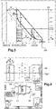
- the assistance method 10 can also include display steps 18, 19, 20 allowing the pilot of the rotorcraft 1 to quickly monitor the correct operation of the assistance method 10.
- this display step 18 is implemented by means of the display device 30 and makes it possible to display information representative of a first deviation between the current position and the landing point PP.
- the current position is illustrated here on the display device 30 by means of a first mark 42, 52.
- the landing point PP is illustrated by a second mark and an H shape 41, 51 centered on the point to ask PP.
- the first difference can then be represented by a distance separating the first marker 42, 52 from the second marker or else from the shape of H 41, 51.
- the shape of H symbolizes for example a helicopter landing strip such as a heliport.
- the assistance method 10 can make it possible to perform a purely vertical take-off phase.
- the shape of H remains centered on the first mark 42 but the size of the H decreases as the rotorcraft 1 gains altitude, then increases again if an emergency landing phase is Implementation.
- the assistance method 10 can make it possible to carry out a take-off phase while backing up, as also shown in picture 3 .
- the shape of H 51 then deviates from the first mark 52 as the rotorcraft 1 gains altitude.
- the display step 19 on the display device 30 makes it possible to display information representative of a second difference between the current position and a zone comprising an obstacle.
- the information displayed is representative of an angular position in azimuth of the rotorcraft as a function of its current position with respect to said touchdown point PP and/or with respect to said zone comprising an obstacle.
- An angular sector 60, 70 is then displayed according to a perspective view of a compass dial 63, 73 comprising a graduated scale of circular or elliptical shape and at least one heading information.
- the color, the shape and/or the width of this angular sector 60, 70 can be modified according to the value of the first or of the second difference.
- the information displayed then makes it possible to provide an alarm signal when, for example, one of the deviations is less than a predetermined threshold value.
- a first alarm level can then be indicated to the pilot by displaying a colored angular sector 60, for example in orange and/or with a first thickness, when a first predetermined threshold value is crossed.
- a second alarm level can be indicated to the pilot by displaying a colored angular sector 70, for example of red color and/or with a second thickness greater than the first thickness, when a second predetermined threshold value, distinct from the first value of predetermined threshold, is crossed.
- the display step 20 can make it possible to display on the display device 30 information representative of a third deviation between the current height of the rotorcraft 1 and the predetermined height of the decision point TDP, LDP.
- Such a third deviation is represented here by means of a colored band 40, 50 extending between the predetermined height of the decision point TDP and the height of the current of the rotorcraft 1.
Applications Claiming Priority (1)
| Application Number | Priority Date | Filing Date | Title |
|---|---|---|---|
| FR2105645A FR3123315A1 (fr) | 2021-05-31 | 2021-05-31 | Procédé d’assistance au pilotage d’un giravion comportant au moins deux moteurs |
Publications (2)
| Publication Number | Publication Date |
|---|---|
| EP4099117A1 true EP4099117A1 (de) | 2022-12-07 |
| EP4099117B1 EP4099117B1 (de) | 2023-07-05 |
Family
ID=77913167
Family Applications (1)
| Application Number | Title | Priority Date | Filing Date |
|---|---|---|---|
| EP22170920.7A Active EP4099117B1 (de) | 2021-05-31 | 2022-04-29 | Hilfsverfahren zum steuern eines drehflügelflugzeugs, das mindestens zwei motoren umfasst |
Country Status (6)
| Country | Link |
|---|---|
| US (1) | US20220380020A1 (de) |
| EP (1) | EP4099117B1 (de) |
| JP (1) | JP2022184747A (de) |
| CN (1) | CN115477005A (de) |
| CA (1) | CA3157276A1 (de) |
| FR (1) | FR3123315A1 (de) |
Citations (6)
| Publication number | Priority date | Publication date | Assignee | Title |
|---|---|---|---|---|
| DE4420059A1 (de) * | 1994-06-08 | 1995-12-14 | Leubner Hans Peter | Start- und Landeführungssystem für Drehflügler und andere Senkrechtstarter |
| US6527225B1 (en) | 2002-04-30 | 2003-03-04 | Sikorsky Aircraft Corporation | Method for performing an automated category a takeoff |
| US6629023B1 (en) | 2002-04-30 | 2003-09-30 | Sikorsky Aircraft Corporation | Method for performing an automated category a approach maneuver |
| FR2900385A1 (fr) | 2006-04-28 | 2007-11-02 | Eurocopter France | Procede et dispositif d'aide au pilotage d'un giravion au decollage. |
| US9193450B2 (en) * | 2012-02-24 | 2015-11-24 | Bell Helicopter Textron Inc. | System and method for automation of rotorcraft entry into autorotation and maintenance of stabilized autorotation |
| EP3444696A1 (de) | 2017-08-17 | 2019-02-20 | Bell Helicopter Textron Inc. | Drehflüglermehrfachprofilführung für cat a |
Family Cites Families (2)
| Publication number | Priority date | Publication date | Assignee | Title |
|---|---|---|---|---|
| JP2913581B2 (ja) * | 1996-03-18 | 1999-06-28 | 株式会社コミュータヘリコプタ先進技術研究所 | ヘリコプタta級離着陸支援装置 |
| FR3064303B1 (fr) * | 2017-03-27 | 2019-05-03 | Safran Helicopter Engines | Dispositif ameliore d'augmentation temporaire de puissance de turbomachine |
-
2021
- 2021-05-31 FR FR2105645A patent/FR3123315A1/fr active Pending
-
2022
- 2022-04-29 EP EP22170920.7A patent/EP4099117B1/de active Active
- 2022-05-03 CA CA3157276A patent/CA3157276A1/fr active Pending
- 2022-05-09 JP JP2022076891A patent/JP2022184747A/ja active Pending
- 2022-05-16 US US17/745,534 patent/US20220380020A1/en active Pending
- 2022-05-23 CN CN202210567257.XA patent/CN115477005A/zh active Pending
Patent Citations (6)
| Publication number | Priority date | Publication date | Assignee | Title |
|---|---|---|---|---|
| DE4420059A1 (de) * | 1994-06-08 | 1995-12-14 | Leubner Hans Peter | Start- und Landeführungssystem für Drehflügler und andere Senkrechtstarter |
| US6527225B1 (en) | 2002-04-30 | 2003-03-04 | Sikorsky Aircraft Corporation | Method for performing an automated category a takeoff |
| US6629023B1 (en) | 2002-04-30 | 2003-09-30 | Sikorsky Aircraft Corporation | Method for performing an automated category a approach maneuver |
| FR2900385A1 (fr) | 2006-04-28 | 2007-11-02 | Eurocopter France | Procede et dispositif d'aide au pilotage d'un giravion au decollage. |
| US9193450B2 (en) * | 2012-02-24 | 2015-11-24 | Bell Helicopter Textron Inc. | System and method for automation of rotorcraft entry into autorotation and maintenance of stabilized autorotation |
| EP3444696A1 (de) | 2017-08-17 | 2019-02-20 | Bell Helicopter Textron Inc. | Drehflüglermehrfachprofilführung für cat a |
Also Published As
| Publication number | Publication date |
|---|---|
| CN115477005A (zh) | 2022-12-16 |
| US20220380020A1 (en) | 2022-12-01 |
| FR3123315A1 (fr) | 2022-12-02 |
| EP4099117B1 (de) | 2023-07-05 |
| JP2022184747A (ja) | 2022-12-13 |
| KR20220162047A (ko) | 2022-12-07 |
| CA3157276A1 (fr) | 2022-11-30 |
Similar Documents
| Publication | Publication Date | Title |
|---|---|---|
| CA3064098C (fr) | Procede d'assistance pour aeronef monomoteur a voilure tournante lors d'une panne moteur | |
| CA2590991C (fr) | Equilibrage en puissance de deux turbomoteurs d'un aeronef | |
| CA2894917C (fr) | Methode de regulation de la vitesse de rotation du rotor principal d'un giravion multi-moteur en cas de panne de l'un des moteurs | |
| EP3095695A1 (de) | Betätigungsverfahren eines elektromotors einer hybridanlage eines mehrmotorigen luftfahrzeugs, und entsprechendes luftfahrzeug | |
| EP2546715B1 (de) | Selbststeuerungsverfahren eines Drehflügelflugzeugs, das mindestens einen Druckpropeller umfasst, entsprechende Autopilot und Flugzeug | |
| EP3025964B1 (de) | Flugassistenzsystem eines mehrmotorigen drehflüglers im falle einer motorpanne im rahmen eines hauptrotorantriebs mit variabler geschwindigkeit | |
| EP3064437B1 (de) | Verfahren und vorrichtung zur bestimmung und optimierung von kennwerten der betriebsfunktion eines drehflügelflugzeugs | |
| EP2597035B1 (de) | Hilfssteuerungsverfahren eines Drehflügelflugzeugs, das mindestens eine Druckschraube umfasst, Hilfssteuerungsvorrichtung und Luftfahrzeug | |
| EP2289060B1 (de) | Anpassung selektiver gebietsalarme als funktion der sofortigen manövrierbarkeit eines flugzeugs | |
| EP3098579B1 (de) | Verfahren zur schätzung der momentanen masse eines drehflügelfluggerätes | |
| EP3147212B1 (de) | Vorrichtung zur regelung der drehzahl des rotors eines drehflügelflugzeugs, mit einer solchen vorrichtung ausgestattetes drehflügelflugzeug und entsprechende regelungsmethode | |
| EP2666719A1 (de) | Verfahren zur Steuerung der Flügelklappen und des horizontalen Leitwerks eines Hybridhelikopters | |
| EP2301844A1 (de) | Verfahren und Vorrichtung zur Steuerungshilfe eines Flugzeuges im Störungsfall eines Instruments für die erste Begrenzung | |
| EP4099117B1 (de) | Hilfsverfahren zum steuern eines drehflügelflugzeugs, das mindestens zwei motoren umfasst | |
| EP3671697A1 (de) | Verfahren zur erkennung der nähe einer seitlichen anordnung eines flugzeugs mit boden und flugzeug | |
| EP3868659B1 (de) | Vorrichtung zur überwachung eines schubkraftspielraums für drehflügelflugzeug, entsprechendes drehflügelflugzeug und verfahren | |
| EP3882141B1 (de) | Verfahren und system zur reduzierung der fluggeräusche eines hybridhubschraubers durch steuerung der anströmung seines hauptrotors und des schubs jedes propellers | |
| EP3733508B1 (de) | Regulierungsverfahren für antriebsanlage eines drehflügelflugzeugs, und entsprechendes drehflügelflugzeug | |
| EP3868658B1 (de) | Verfahren zur steuerung eines hybrid-helikopters im falle eines ausfalls einer antriebsanlage | |
| EP1110131B1 (de) | Verfahren und vorrichtung zum steuern der flughöhe eines flugzeuges mit automatischem wechsel zwischen druckhöhe und radarhöhe |
Legal Events
| Date | Code | Title | Description |
|---|---|---|---|
| PUAI | Public reference made under article 153(3) epc to a published international application that has entered the european phase |
Free format text: ORIGINAL CODE: 0009012 |
|
| STAA | Information on the status of an ep patent application or granted ep patent |
Free format text: STATUS: THE APPLICATION HAS BEEN PUBLISHED |
|
| AK | Designated contracting states |
Kind code of ref document: A1 Designated state(s): AL AT BE BG CH CY CZ DE DK EE ES FI FR GB GR HR HU IE IS IT LI LT LU LV MC MK MT NL NO PL PT RO RS SE SI SK SM TR |
|
| STAA | Information on the status of an ep patent application or granted ep patent |
Free format text: STATUS: REQUEST FOR EXAMINATION WAS MADE |
|
| 17P | Request for examination filed |
Effective date: 20221215 |
|
| RBV | Designated contracting states (corrected) |
Designated state(s): AL AT BE BG CH CY CZ DE DK EE ES FI FR GB GR HR HU IE IS IT LI LT LU LV MC MK MT NL NO PL PT RO RS SE SI SK SM TR |
|
| GRAP | Despatch of communication of intention to grant a patent |
Free format text: ORIGINAL CODE: EPIDOSNIGR1 |
|
| STAA | Information on the status of an ep patent application or granted ep patent |
Free format text: STATUS: GRANT OF PATENT IS INTENDED |
|
| INTG | Intention to grant announced |
Effective date: 20230314 |
|
| RIN1 | Information on inventor provided before grant (corrected) |
Inventor name: CALMES, NICOLAS Inventor name: RAYNAUD, GUILLAUME |
|
| GRAS | Grant fee paid |
Free format text: ORIGINAL CODE: EPIDOSNIGR3 |
|
| GRAA | (expected) grant |
Free format text: ORIGINAL CODE: 0009210 |
|
| STAA | Information on the status of an ep patent application or granted ep patent |
Free format text: STATUS: THE PATENT HAS BEEN GRANTED |
|
| AK | Designated contracting states |
Kind code of ref document: B1 Designated state(s): AL AT BE BG CH CY CZ DE DK EE ES FI FR GB GR HR HU IE IS IT LI LT LU LV MC MK MT NL NO PL PT RO RS SE SI SK SM TR |
|
| P01 | Opt-out of the competence of the unified patent court (upc) registered |
Effective date: 20230530 |
|
| REG | Reference to a national code |
Ref country code: CH Ref legal event code: EP |
|
| REG | Reference to a national code |
Ref country code: AT Ref legal event code: REF Ref document number: 1585425 Country of ref document: AT Kind code of ref document: T Effective date: 20230715 |
|
| REG | Reference to a national code |
Ref country code: DE Ref legal event code: R096 Ref document number: 602022000171 Country of ref document: DE |
|
| REG | Reference to a national code |
Ref country code: IE Ref legal event code: FG4D Free format text: LANGUAGE OF EP DOCUMENT: FRENCH |
|
| REG | Reference to a national code |
Ref country code: LT Ref legal event code: MG9D |
|
| REG | Reference to a national code |
Ref country code: NL Ref legal event code: MP Effective date: 20230705 |
|
| REG | Reference to a national code |
Ref country code: AT Ref legal event code: MK05 Ref document number: 1585425 Country of ref document: AT Kind code of ref document: T Effective date: 20230705 |
|
| PG25 | Lapsed in a contracting state [announced via postgrant information from national office to epo] |
Ref country code: NL Free format text: LAPSE BECAUSE OF FAILURE TO SUBMIT A TRANSLATION OF THE DESCRIPTION OR TO PAY THE FEE WITHIN THE PRESCRIBED TIME-LIMIT Effective date: 20230705 |
|
| PG25 | Lapsed in a contracting state [announced via postgrant information from national office to epo] |
Ref country code: GR Free format text: LAPSE BECAUSE OF FAILURE TO SUBMIT A TRANSLATION OF THE DESCRIPTION OR TO PAY THE FEE WITHIN THE PRESCRIBED TIME-LIMIT Effective date: 20231006 |
|
| PG25 | Lapsed in a contracting state [announced via postgrant information from national office to epo] |
Ref country code: ES Free format text: LAPSE BECAUSE OF FAILURE TO SUBMIT A TRANSLATION OF THE DESCRIPTION OR TO PAY THE FEE WITHIN THE PRESCRIBED TIME-LIMIT Effective date: 20230705 |
|
| PG25 | Lapsed in a contracting state [announced via postgrant information from national office to epo] |
Ref country code: IS Free format text: LAPSE BECAUSE OF FAILURE TO SUBMIT A TRANSLATION OF THE DESCRIPTION OR TO PAY THE FEE WITHIN THE PRESCRIBED TIME-LIMIT Effective date: 20231105 |
|
| PG25 | Lapsed in a contracting state [announced via postgrant information from national office to epo] |
Ref country code: SE Free format text: LAPSE BECAUSE OF FAILURE TO SUBMIT A TRANSLATION OF THE DESCRIPTION OR TO PAY THE FEE WITHIN THE PRESCRIBED TIME-LIMIT Effective date: 20230705 Ref country code: RS Free format text: LAPSE BECAUSE OF FAILURE TO SUBMIT A TRANSLATION OF THE DESCRIPTION OR TO PAY THE FEE WITHIN THE PRESCRIBED TIME-LIMIT Effective date: 20230705 Ref country code: PT Free format text: LAPSE BECAUSE OF FAILURE TO SUBMIT A TRANSLATION OF THE DESCRIPTION OR TO PAY THE FEE WITHIN THE PRESCRIBED TIME-LIMIT Effective date: 20231106 Ref country code: NO Free format text: LAPSE BECAUSE OF FAILURE TO SUBMIT A TRANSLATION OF THE DESCRIPTION OR TO PAY THE FEE WITHIN THE PRESCRIBED TIME-LIMIT Effective date: 20231005 Ref country code: LV Free format text: LAPSE BECAUSE OF FAILURE TO SUBMIT A TRANSLATION OF THE DESCRIPTION OR TO PAY THE FEE WITHIN THE PRESCRIBED TIME-LIMIT Effective date: 20230705 Ref country code: LT Free format text: LAPSE BECAUSE OF FAILURE TO SUBMIT A TRANSLATION OF THE DESCRIPTION OR TO PAY THE FEE WITHIN THE PRESCRIBED TIME-LIMIT Effective date: 20230705 Ref country code: IS Free format text: LAPSE BECAUSE OF FAILURE TO SUBMIT A TRANSLATION OF THE DESCRIPTION OR TO PAY THE FEE WITHIN THE PRESCRIBED TIME-LIMIT Effective date: 20231105 Ref country code: HR Free format text: LAPSE BECAUSE OF FAILURE TO SUBMIT A TRANSLATION OF THE DESCRIPTION OR TO PAY THE FEE WITHIN THE PRESCRIBED TIME-LIMIT Effective date: 20230705 Ref country code: GR Free format text: LAPSE BECAUSE OF FAILURE TO SUBMIT A TRANSLATION OF THE DESCRIPTION OR TO PAY THE FEE WITHIN THE PRESCRIBED TIME-LIMIT Effective date: 20231006 Ref country code: FI Free format text: LAPSE BECAUSE OF FAILURE TO SUBMIT A TRANSLATION OF THE DESCRIPTION OR TO PAY THE FEE WITHIN THE PRESCRIBED TIME-LIMIT Effective date: 20230705 Ref country code: ES Free format text: LAPSE BECAUSE OF FAILURE TO SUBMIT A TRANSLATION OF THE DESCRIPTION OR TO PAY THE FEE WITHIN THE PRESCRIBED TIME-LIMIT Effective date: 20230705 Ref country code: AT Free format text: LAPSE BECAUSE OF FAILURE TO SUBMIT A TRANSLATION OF THE DESCRIPTION OR TO PAY THE FEE WITHIN THE PRESCRIBED TIME-LIMIT Effective date: 20230705 |
|
| PG25 | Lapsed in a contracting state [announced via postgrant information from national office to epo] |
Ref country code: PL Free format text: LAPSE BECAUSE OF FAILURE TO SUBMIT A TRANSLATION OF THE DESCRIPTION OR TO PAY THE FEE WITHIN THE PRESCRIBED TIME-LIMIT Effective date: 20230705 |
|
| PG25 | Lapsed in a contracting state [announced via postgrant information from national office to epo] |
Ref country code: SM Free format text: LAPSE BECAUSE OF FAILURE TO SUBMIT A TRANSLATION OF THE DESCRIPTION OR TO PAY THE FEE WITHIN THE PRESCRIBED TIME-LIMIT Effective date: 20230705 Ref country code: RO Free format text: LAPSE BECAUSE OF FAILURE TO SUBMIT A TRANSLATION OF THE DESCRIPTION OR TO PAY THE FEE WITHIN THE PRESCRIBED TIME-LIMIT Effective date: 20230705 Ref country code: EE Free format text: LAPSE BECAUSE OF FAILURE TO SUBMIT A TRANSLATION OF THE DESCRIPTION OR TO PAY THE FEE WITHIN THE PRESCRIBED TIME-LIMIT Effective date: 20230705 Ref country code: DK Free format text: LAPSE BECAUSE OF FAILURE TO SUBMIT A TRANSLATION OF THE DESCRIPTION OR TO PAY THE FEE WITHIN THE PRESCRIBED TIME-LIMIT Effective date: 20230705 Ref country code: CZ Free format text: LAPSE BECAUSE OF FAILURE TO SUBMIT A TRANSLATION OF THE DESCRIPTION OR TO PAY THE FEE WITHIN THE PRESCRIBED TIME-LIMIT Effective date: 20230705 Ref country code: SK Free format text: LAPSE BECAUSE OF FAILURE TO SUBMIT A TRANSLATION OF THE DESCRIPTION OR TO PAY THE FEE WITHIN THE PRESCRIBED TIME-LIMIT Effective date: 20230705 |