EP4099098A1 - Developer storage device and image forming apparatus - Google Patents
Developer storage device and image forming apparatus Download PDFInfo
- Publication number
- EP4099098A1 EP4099098A1 EP22174148.1A EP22174148A EP4099098A1 EP 4099098 A1 EP4099098 A1 EP 4099098A1 EP 22174148 A EP22174148 A EP 22174148A EP 4099098 A1 EP4099098 A1 EP 4099098A1
- Authority
- EP
- European Patent Office
- Prior art keywords
- developer
- chamber
- storage device
- conveyance screw
- screw
- Prior art date
- Legal status (The legal status is an assumption and is not a legal conclusion. Google has not performed a legal analysis and makes no representation as to the accuracy of the status listed.)
- Pending
Links
- 238000001514 detection method Methods 0.000 claims abstract description 23
- 238000004891 communication Methods 0.000 claims abstract description 18
- 238000005192 partition Methods 0.000 claims abstract description 15
- 230000005484 gravity Effects 0.000 claims description 11
- 230000001105 regulatory effect Effects 0.000 claims description 5
- 238000000638 solvent extraction Methods 0.000 abstract description 2
- 238000010586 diagram Methods 0.000 description 26
- 239000003795 chemical substances by application Substances 0.000 description 8
- 238000004140 cleaning Methods 0.000 description 6
- 239000000463 material Substances 0.000 description 6
- 230000005540 biological transmission Effects 0.000 description 5
- 238000000034 method Methods 0.000 description 5
- 239000003086 colorant Substances 0.000 description 2
- 238000010438 heat treatment Methods 0.000 description 2
- 230000003287 optical effect Effects 0.000 description 2
- 230000003247 decreasing effect Effects 0.000 description 1
- 238000011144 upstream manufacturing Methods 0.000 description 1
Images




Classifications
-
- G—PHYSICS
- G03—PHOTOGRAPHY; CINEMATOGRAPHY; ANALOGOUS TECHNIQUES USING WAVES OTHER THAN OPTICAL WAVES; ELECTROGRAPHY; HOLOGRAPHY
- G03G—ELECTROGRAPHY; ELECTROPHOTOGRAPHY; MAGNETOGRAPHY
- G03G21/00—Arrangements not provided for by groups G03G13/00 - G03G19/00, e.g. cleaning, elimination of residual charge
- G03G21/10—Collecting or recycling waste developer
- G03G21/105—Arrangements for conveying toner waste
-
- G—PHYSICS
- G03—PHOTOGRAPHY; CINEMATOGRAPHY; ANALOGOUS TECHNIQUES USING WAVES OTHER THAN OPTICAL WAVES; ELECTROGRAPHY; HOLOGRAPHY
- G03G—ELECTROGRAPHY; ELECTROPHOTOGRAPHY; MAGNETOGRAPHY
- G03G15/00—Apparatus for electrographic processes using a charge pattern
- G03G15/06—Apparatus for electrographic processes using a charge pattern for developing
- G03G15/08—Apparatus for electrographic processes using a charge pattern for developing using a solid developer, e.g. powder developer
- G03G15/0822—Arrangements for preparing, mixing, supplying or dispensing developer
- G03G15/0887—Arrangements for conveying and conditioning developer in the developing unit, e.g. agitating, removing impurities or humidity
- G03G15/0891—Arrangements for conveying and conditioning developer in the developing unit, e.g. agitating, removing impurities or humidity for conveying or circulating developer, e.g. augers
-
- G—PHYSICS
- G03—PHOTOGRAPHY; CINEMATOGRAPHY; ANALOGOUS TECHNIQUES USING WAVES OTHER THAN OPTICAL WAVES; ELECTROGRAPHY; HOLOGRAPHY
- G03G—ELECTROGRAPHY; ELECTROPHOTOGRAPHY; MAGNETOGRAPHY
- G03G15/00—Apparatus for electrographic processes using a charge pattern
- G03G15/06—Apparatus for electrographic processes using a charge pattern for developing
- G03G15/08—Apparatus for electrographic processes using a charge pattern for developing using a solid developer, e.g. powder developer
- G03G15/0822—Arrangements for preparing, mixing, supplying or dispensing developer
- G03G15/0848—Arrangements for testing or measuring developer properties or quality, e.g. charge, size, flowability
- G03G15/0856—Detection or control means for the developer level
-
- G—PHYSICS
- G03—PHOTOGRAPHY; CINEMATOGRAPHY; ANALOGOUS TECHNIQUES USING WAVES OTHER THAN OPTICAL WAVES; ELECTROGRAPHY; HOLOGRAPHY
- G03G—ELECTROGRAPHY; ELECTROPHOTOGRAPHY; MAGNETOGRAPHY
- G03G21/00—Arrangements not provided for by groups G03G13/00 - G03G19/00, e.g. cleaning, elimination of residual charge
- G03G21/10—Collecting or recycling waste developer
- G03G21/12—Toner waste containers
-
- G—PHYSICS
- G03—PHOTOGRAPHY; CINEMATOGRAPHY; ANALOGOUS TECHNIQUES USING WAVES OTHER THAN OPTICAL WAVES; ELECTROGRAPHY; HOLOGRAPHY
- G03G—ELECTROGRAPHY; ELECTROPHOTOGRAPHY; MAGNETOGRAPHY
- G03G2221/00—Processes not provided for by group G03G2215/00, e.g. cleaning or residual charge elimination
- G03G2221/16—Mechanical means for facilitating the maintenance of the apparatus, e.g. modular arrangements and complete machine concepts
- G03G2221/1618—Mechanical means for facilitating the maintenance of the apparatus, e.g. modular arrangements and complete machine concepts for the cleaning unit
- G03G2221/1624—Mechanical means for facilitating the maintenance of the apparatus, e.g. modular arrangements and complete machine concepts for the cleaning unit transporting cleaned toner into separate vessels, e.g. photoreceptors, external containers
Definitions
- the present invention relates to a developer storage device that can store powdery developer and an image forming apparatus that uses the developer storage device.
- the present invention particularly relates to, in particular, an electrophotographic image forming apparatus adopting an electrophotographic method and a developer storage device.
- a toner image formed on a photosensitive drum, an intermediate transfer belt, and the like may not be completely transferred to a recording medium such as a sheet, and part of toner may remain on the photosensitive drum, the intermediate transfer belt, and the like.
- Remaining toner (residual toner) is removed from the photosensitive drum, the intermediate transfer belt, and the like by a cleaning unit and conveyed (collected) by a toner conveyance unit to a toner storage container arranged inside the image forming apparatus.
- an image forming apparatus is discussed in which a toner storage container is replaceable with a new one in a case where an amount of residual toner collected in the toner storage container reaches an upper limit value of a storage capacity thereof.
- a user is notified of a replacement time and prompted to prepare a new toner storage container before the residual toner amount in the toner storage container reaches the upper limit value of the storage capacity so that a period during which the image forming apparatus cannot be used is shortened.
- a shape of the toner storage container is a "vertically long shape” in which a length in a "gravity direction” is long and a length in a “horizontal direction” is short in a posture during use.
- a toner inlet is provided on an upper side of the toner storage container in the gravity direction.
- a first detection unit constantly monitors a toner agent level and performs "replacement notice display" for the toner storage container to a user in a case where the toner agent level at a predetermined height is detected.
- a second detection unit calculates (predicts) the residual toner amount from a received image signal and, in a case where the toner amount reaches a threshold value (the upper limit value of the storage capacity), performs "full” warning display to a user and also stops an image forming operation of the image forming apparatus until the toner storage container is replaced.
- a threshold value the upper limit value of the storage capacity
- the image forming operation can be continuously performed for a while after the "replacement notice display" is performed to the user.
- the "shape" of a toner storage container may be restricted so as to fit into an internal storage space of the miniaturized image forming apparatus.
- the "vertically long shape" according to Japanese Patent Application Laid-Open No. 2003-248402 requires a certain height (length) or more in the gravity direction (a height direction).
- the toner storage container may have a "horizontally long shape" in which a length in the gravity direction is short and a length in the horizontal direction is long.
- a "toner agent level” is more likely to be unstable, and detection accuracy of the "toner agent level” may be decreased compared with the "vertically long shape” according to Japanese Patent Application Laid-Open No. 2003-248402 .
- the "replacement notice display” is performed for the toner storage container having the "horizontally long shape” based on a detection result of the "toner agent level” as discussed in Japanese Patent Application Laid-Open No. 2003-248402 , a period during which the image forming operation can be continued after the "replacement notice display” may significantly vary. As a result, the accuracy in determining a service life or the replacement time of the toner storage container may be reduced.
- the present invention is directed to the provision of a configuration that enables accurate determination of a service life or a replacement time even if a shape of a storage unit of a developer storage device is a horizontally long shape in which a length in the gravity direction is short and a length in the horizontal direction is long in a posture during use.
- a developer storage device as specified in claims 1 to 11.
- an image forming apparatus as specified in claims 12 and 13.
- another image forming apparatus as specified in claim 14.
- an electrophotographic image forming apparatus refers to an apparatus that forms an image on a recording medium by an electrophotographic image forming method.
- Examples of an electrophotographic image forming apparatus include an electrophotographic copying machine, an electrophotographic printer (e.g., a laser beam printer and a light emitting diode (LED) printer), a facsimile device, and a word processor.
- an electrophotographic printer e.g., a laser beam printer and a light emitting diode (LED) printer
- a facsimile device e.g., a facsimile device.
- a developer storage device is used in an image forming apparatus and is attachable to and detachable from a main body of the image forming apparatus.
- FIG. 1A A first embodiment of the present invention will be described.
- An image forming apparatus 1 according to the present embodiment will be described below with reference to Figs. 1A to 7B .
- Fig. 2 is a main cross-section conceptual diagram illustrating an overall configuration of the image forming apparatus 1 according to the first embodiment of the present invention.
- Fig. 3 is a side cross-section conceptual diagram illustrating the overall configuration of the image forming apparatus 1 according to the first embodiment of the present invention.
- a "vertical direction” indicated in the drawings is the gravity direction, and a “right-and-left direction” and a “back-and-forth direction” are the horizontal direction.
- a cassette 2 is stored in a drawable manner in a lower part of the image forming apparatus 1.
- a cassette feed unit 3 is arranged near an end of the cassette 2. Transfer materials are stacked and stored in the cassette 2, separated one by one, and fed to a registration roller 5.
- the image forming apparatus 1 includes image forming stations 6 (Y, M, C, and K) (also referred to as image forming units 6) corresponding to respective colors of yellow, magenta, cyan, black as image forming units horizontally arranged in line.
- image forming stations 6 Y, M, C, and K
- image forming units 6 also referred to as image forming units 6
- the image forming units 6 include photosensitive drums 7 (Y, M, C, and K) serving as image bearing members and charging devices 8 (Y, M, C, and K) that uniformly charge surfaces of the photosensitive drums 7.
- the image forming units 6 further include development devices 9 (Y, M, C, and K) that cause toner to adhere to electrostatic latent images and develop them as toner images and photosensitive member cleaning blades 10 (Y, M, C, and K) (first collecting members) that remove residual toner remaining on the photosensitive drums 7.
- the development devices 9 are provided with development rollers 11 (Y, M, C, and K) corresponding to the respective colors so as to be able to come into contact with and separate from the respective photosensitive drums 7.
- the development rollers 11 are brought into contact with or separated from the photosensitive drums 7 in agreement with the electrostatic latent images, which improves lives of the development rollers 11.
- a scanner unit 12 that forms the electrostatic latent images on the photosensitive drums 7 by emitting laser beams based on image information is arranged below the image forming units 6.
- An intermediate transfer unit 16 is arranged above the development devices 9.
- the intermediate transfer unit 16 is arranged substantially horizontally with a secondary transfer portion 17 side below.
- An intermediate transfer belt 18 (an intermediate transfer member) facing the respective photosensitive drum 7 is a rotatable endless belt and is stretched on a plurality of stretching rollers.
- primary transfer rollers 19 (Y, M, C, and K) as primary transfer members are respectively arranged in positions at which primary transfer portions 20 (Y, M, C, and K) are formed with the respective photosensitive drums 7 via the intermediate transfer belt 18.
- the toner images are transferred from the respective photosensitive drums 7 to the intermediate transfer belt 18 by the primary transfer rollers 19 to which voltage is applied at the respective primary transfer portions 20.
- a unit including the intermediate transfer belt 18, the plurality of stretching rollers on which the intermediate transfer belt 18 is stretched, and the respective primary transfer rollers 19 is configured as the intermediate transfer unit 16 that is attachable to and detachable from the main body of the apparatus.
- a secondary transfer roller 21 serving as a secondary transfer member is in contact with the intermediate transfer belt 18 and forms the secondary transfer portion 17 with a roller on an opposite side via the intermediate transfer belt 18.
- the toner image transferred on the intermediate transfer belt 18 in the secondary transfer portion 17 is secondarily transferred to the transfer material.
- the residual toner that cannot be completely transferred to the transfer material in the secondary transfer and remains on the intermediate transfer belt 18 is removed by a cleaning unit 22 (a second collecting member or a collecting member).
- the toner removed by the cleaning unit 22 is conveyed to and accumulated in a toner collecting container 24 (a developer storage device) via a collected toner conveyance unit 23.
- the toner that cannot be transferred to the intermediate transfer belt 18 and remains on the photosensitive drums 7 is conveyed to the collected toner conveyance unit 23 via a cartridge collected toner conveyance unit 29 and further conveyed to the toner collecting container 24.
- the toner collecting container 24 can store the "residual toner" from at least one or both of the photosensitive drums 7 and the intermediate transfer belt 18.
- the residual toner is collected by the photosensitive member cleaning blades 10 or the cleaning unit 22 and then conveyed to the toner collecting container 24 by a conveyance unit.
- the transfer material is conveyed to a fixing device 25 and passes through a nip formed by a heating unit 25a and a pressure roller 25b that is in pressure contact with the heating unit 25a, in the fixing device 25.
- the transfer material that has passed through the fixing device 25 is conveyed to a discharge roller pair 26 and discharged to a sheet discharge tray 27.
- a low voltage power supply device (not illustrated) that supplies voltage to control units of various motors, fans, solenoids, and the like provided in the image forming apparatus 1 is arranged on a rear surface side of the image forming apparatus 1.
- a high voltage power supply device 28 that applies high voltage to the charging devices 8, the development devices 9, the primary transfer rollers 19, the secondary transfer roller 21, and the like is arranged in a space between the intermediate transfer belt 18 and the toner collecting container 24 on the rear surface side of the image forming apparatus 1.
- Fig. 1A is a top conceptual diagram illustrating the developer storage device according to the first embodiment of the present invention
- Fig. 1B is a perspective conceptual diagram illustrating the developer storage device
- Fig. 1C is a top conceptual diagram illustrating the developer storage device in a state in which the inside thereof is exposed with an upper structure thereof removed
- Fig. ID is a perspective conceptual diagram illustrating the developer storage device in a state in which the inside thereof is exposed with the upper structure thereof removed.
- Fig. 1A illustrates a state of a top surface of the toner collecting container 24.
- Fig. 1B illustrates a state of the toner collecting container 24 viewed from obliquely above.
- Fig. 1C illustrates a state in which an upper structure 24a of the toner collecting container 24 is removed, and
- Fig. ID illustrates a state in which the toner collecting container 24 with the upper structure 24a removed is viewed from obliquely above.
- the toner conveyed by the collected toner conveyance unit 23 (refer to Fig. 3 ) is received in the toner collecting container 24 from a toner supply port 30 (an inlet).
- the toner collecting container 24 has a horizontally long shape in which a length in the "right-and-left direction" and the "back-and-forth direction", which are the horizontal direction is longer than a length in the vertical direction, which is the gravity direction.
- the toner collecting container 24 can form an internal space IS for collecting toner inside a frame 24F by connecting the upper structure 24a and a lower structure 24b, which form the frame 24F.
- the internal space of the toner collecting container 24 is partitioned into a first storage chamber 33 (a first chamber) and a second storage chamber 34 (a second chamber) by a partition 35 (a partition portion).
- the partitioned internal space having a smaller volume is referred to as the second storage chamber 34, and the internal space other than the second storage chamber 34 is referred to as the first storage chamber 33.
- the partition 35 is provided with a communication port 36 with which the first storage chamber 33 and the second storage chamber 34 communicate.
- a first screw 31 (a first conveyance screw) and a second screw 32 (a second conveyance screw) that form a conveyance member (conveyance portion) 3T are arranged side by side in the horizontal direction below the toner supply port 30.
- the second screw 32 is longer than the first screw 31 and extends to near a center of the first storage chamber 33.
- the position of the communication port 36 (a communication port side) is located on an opposite side of the second screw 32 with reference to the first screw 31, and a lower end position 311 of the first screw 31 is located below a lower end position 361 of the communication port 36.
- the first screw 31 is arranged directly below the toner supply port 30, and the second screw 32 is arranged to extend from a toner supply port side S1 (an inlet side) to a far side S2 on the opposite side.
- the frame 24F is formed to have a rectangular (square) shape in a plan view.
- the toner supply port 30 is arranged at a corner portion AG1 of the rectangle.
- the second screw 32 is arranged to extend from a corner portion side (AG1) to a corner portion side (AG2) on the opposite side of the corner portion (AG1) on a diagonal line X1.
- the toner collecting container 24 is provided with the frame 24F that includes the internal space IS for storing the toner and the toner supply port 30 for feeding the toner into the internal space.
- the toner collecting container 24 is provided with the partition 35 that partitions the internal space into the first storage chamber 33 and the second storage chamber 34, which has a smaller volume than the first storage chamber 33, which are arranged side by side in the horizontal direction in the posture during use, and includes the communication port 36 with which the first storage chamber 33 and the second storage chamber 34 communicate.
- the first screw 31 and the second screw 32 that convey the toner fed from the toner supply port are arranged in the internal space IS.
- Figs. 4A and 4B are conceptual diagrams illustrating an operation of a detection unit in the developer storage device according to the first embodiment of the present invention.
- a lever 37 interlocking with the second screw 32 is arranged downstream of the second screw 32 in the first storage chamber 33.
- the lever 37 reciprocates between a position at which an optical axis 41a of a photosensor 41 is shielded from light as illustrated in Fig. 4A and a position at which the lever 37 does not shield the optical axis 41a of the photosensor 41 by moving forward and allows light to pass through as illustrated in Fig. 4B .
- the lever 37 and the photosensor 41 form a detection unit (detection means) SR of the present invention.
- Figs. 4A and 4B illustrate a state in which the upper structure 24a is removed for the sake of description. If the second screw 32 makes one rotation, the lever 37 reciprocates once.
- the first screw 31 is connected to a drive transmission gear 38 and is driven if the drive transmission gear 38 is driven by a drive unit (not illustrated).
- the second screw 32 is connected to a driven gear 39 via a torque limiter 40 (a rotation regulating member) serving as a rotation regulating unit, and the driven gear 39 is driven by engaging with the drive transmission gear 38.
- Fig. 5A is an enlarged plan conceptual diagram illustrating near an inlet of the developer storage device according to the first embodiment of the present invention
- Fig. 5B is an enlarged cross-section conceptual diagram illustrating near the inlet.
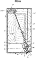
- Fig. 6 is a conceptual diagram illustrating a filling state of the developer in the first storage chamber in the developer storage device according to the first embodiment of the present invention.
- Fig. 5A illustrates a part near the second screw 32 from the toner supply port 30 in a state in which the upper structure 24a is removed.
- Fig. 5B illustrates a state of a cross section taken along a line D-D in Fig. 1A .
- the toner is supplied from the toner supply port 30 in the state illustrated in Figs. 5A and 5B , the toner is conveyed in an arrow A direction by the first screw 31.
- the toner is conveyed by the first screw 31 until it hits a first screw downstream partition 35a and accumulates in a downstream area of the first screw 31.
- the toner advances along a wall of the first screw downstream partition 35a and spreads in directions of an arrow B and an arrow C.
- a position of the communication port 36 on the partition 35 is located above a lower end of the first screw 31 in the gravity direction as indicated by an arrow E, so that the toner is conveyed by the second screw 32 before a toner agent level rises to enter the second storage chamber 34.
- the second screw 32 has a conveyance amount of the toner greater than that of the first screw 31.
- the second screw 32 is located downstream of the first screw 31, increasing of the conveyance amount in the downstream makes it is possible to prevent stagnation of toner caused by toner that has conveyed from the upstream not being able to be completely conveyed in the downstream.
- the first screw 31 and the second screw 32 arranged in parallel makes it possible to make the conveyance amount of the second screw 32 greater than the conveyance amount of the first screw 31 at least in an area T1 in which the first screw 31 faces the second screw 32.
- This enables the toner to be effectively conveyed to a far side of the first storage chamber 33, thus reducing or preventing stagnation of toner near the toner supply port 30.
- it is possible to reduce or prevent flowing of the toner into the second storage chamber 34 at this point.
- the toner reaches the second screw 32 arranged side by side of the first screw 31 in the horizontal direction, the toner is conveyed to a portion near the center of the first storage chamber 33 in an arrow F direction by the second screw 32.
- the toner conveyed by the second screw 32 concentrically spreads from a screw edge 32a of the second screw 32 into the first storage chamber 33 and accumulates therein.
- the periphery of the second screw 32 is filled with the toner, and a rotational load of the second screw 32 increases because the toner becomes a load for driving the second screw 32. If the rotational load of the second screw 32 exceeds a torque setting value of the torque limiter 40, the second screw 32 and the torque limiter 40 idle, and rotation of the second screw 32 stops.
- the lever 37 interlocking with the second screw 32 also stops.
- a detection result of the photosensor 41 does not switch between shielding and transmission of light within a time period of one rotation of the second screw 32, it is determined that the lever 37 has stopped.
- the detection unit SR (the photosensor 41) can detect the toner amount in the first storage chamber 33 based on a rotation state of the second screw 32.
- Fig. 7A is an enlarged plan conceptual diagram illustrating a conveyance path of the developer to the second storage chamber 34 in the developer storage device according to the first embodiment of the present invention.
- Fig. 7B is an enlarged cross-section conceptual diagram illustrating the conveyance path of the developer to the second storage chamber 34.
- FIGs. 7A and 7B illustrate a state of toner conveyance after the second screw 32 is stopped.
- the first screw 31 is driven after the second screw 32 is stopped, and the toner is conveyed in the arrow A direction and accumulates in a downstream portion of the first screw 31. Since the second screw 32 is stopped, the toner agent level accumulated in the downstream portion of the first screw 31 rises. If the toner agent level exceeds a height of the communication port 36, the toner enters the second storage chamber 34 from the communication port 36 as indicated by an arrow G.
- the amount of toner entering the second storage chamber 34 after the second screw 32 is stopped is calculated from the amount of toner collected based on an image signal printed by a user.
- the calculated toner amount reaches a toner acceptable amount set from a volume of the second storage chamber 34
- the user is notified that the toner collecting container 24 needs to be replaced (hereinbelow, such a notification is described as a replacement necessity notice).
- the image forming apparatus 1 is in a print stop state until the toner collecting container 24 is replaced.
- the toner amount in the first storage chamber 33 is less than a predetermined value (a full value)
- the toner is conveyed to a far side of the first storage chamber 33 by the first and the second screws.
- the rotation of the second screw 32 is stopped, and the toner is not conveyed to the far side of the first storage chamber 33 but conveyed to the second storage chamber 34.
- the toner collecting container 24 is enabled to move toner and store the toner in the second storage chamber 34 after detecting that the toner amount in the first storage chamber 33 reaches the predetermined value (the full value).
- the predetermined value the full value.
- the first screw 31 can be arranged so that the lower end position 311 of the first screw 31 is disposed lower than the lower end position 361 of the communication port 36.
- the lower end of the first screw 31 is located below the lower end of the communication port 36, which increases reliability of, after conveying the toner to the far side of the first storage chamber 33 and the first storage chamber 33 becomes full, conveying the toner to the second storage chamber 34 through the communication port 36.
- a period from when the "replacement notice display" is performed to when the replacement is made can be estimated more accurately, and the accuracy in determining the service life (the replacement time) of the toner collecting container is further improved.
- the first screw 31 and the second screw 32 are arranged nearly parallel to each other and can be configured so that the conveyance amount of the second screw 32 is greater than the conveyance amount of the first screw 31 in the area T1 in which the first screw 31 and the second screw 32 face each other.
- the toner can be transferred more smoothly from the first screw 31 to the second screw 32 and can be conveyed more efficiently to the far side of the first storage chamber 33, so that movement of the toner to the second storage chamber 34 is effectively reduced or prevented in a case where the toner is conveyed to the far side of the first storage chamber 33.
- the replacement notice is displayed for a user to provide a period for preparing a new toner collecting container 24 and to prompt the user to replace the toner collecting container 24 immediately after the replacement necessity notice is issued, a period for stopping printing of the image forming apparatus 1 can be eliminated, thus improving usability.
- the internal space of the toner collecting container 24 is partitioned into two spaces, and the space for storing the toner is changed before and after the replacement notice display, so that the toner can be collected after the replacement notice display until the replacement necessity notice is issued.
- the change of the space for storing the toner is based on a relationship between drive and stop of the two screws and arrangement of the two spaces for storing the toner and can be realized with a low-cost configuration without increasing the number of components.
- Fig. 8 is a top conceptual diagram illustrating a developer storage device according to the second embodiment of the present invention in a state in which an upper structure thereof is removed and an inside is exposed.
- Fig. 8 illustrates a state in which the upper structure 24a is removed.
- the second embodiment has a configuration basically similar to that according to the first embodiment, and a different point will be described below.
- the second embodiment has a configuration in which a second drive transmission unit 42 which is connected to the second screw 32 is connected to a drive source (not illustrated) different from that of the first screw 31, and the first screw 31 and the second screw 32 can rotate independently of each other. Since the second screw 32 can rotate independently, in a case where it is necessary to increase a toner conveyance force without change in a shape of the second screw 32, the conveyance force can be changed by increasing a rotation speed of only the second screw 32.
- the rotation of the second screw 32 can be freely switched between driving and stopping, so that the rotation regulating unit (the torque limiter 40) is not necessary.
- a current value necessary for driving the drive source of the second screw 32 changes depending on the rotational load of the second screw 32
- detecting of the current value of the drive source enables detection of a change in the toner storage amount in the first storage chamber 33.
- a current value in a state in which the first storage chamber 33 is filled with the toner is set to a drive source setting value, and the replacement notice display is output when the current value exceeds the drive source setting value, thus detecting the toner storage amount.
- the drive of the second screw 32 is stopped after the current value exceeds the drive source setting value, thus conveying the toner to the second storage chamber 34 as in the first embodiment.
- the period for stopping printing of the image forming apparatus 1 can be eliminated by displaying the replacement notice to a user to provide a period for preparing a new toner collecting container 24 so that the user is prompted to replace the toner collecting container 24 immediately after the replacement necessity notice is issued. Accordingly, the usability is improved.
- the present invention can be summarized as follows.
- the developer is conveyed from a portion adjacent to the inlet (inlet side (S1)) to the far side (S2) of the first chamber by the conveyance member, and when the detection unit detects that the amount of the developer in the first chamber reaches the predetermined value or more, the conveyance member does not convey the developer to the far side of the first chamber but conveys the developer to the second chamber.
- the conveyance member (3T) can include the first conveyance screw (31) and the second conveyance screw (32) longer than the first conveyance screw.
- the first conveyance screw may be arranged closer to the inlet (30) than the second conveyance screw.
- the first conveyance screw (31) and the second conveyance screw (32) may be arranged side by side in the horizontal direction in the first chamber (33).
- the second conveyance screw can be arranged on the opposite side of the side where the communication port (36) is arranged in the horizontal direction with respect to the first conveyance screw.
- the first conveyance screw (31) may be arranged so that the lower end position (311) of the first conveyance screw is lower than the lower end position (361) of the communication port (36).
- the developer storage device can include the rotation regulating member (40) configured to regulate a rotation operation of the second conveyance screw when a predetermined rotational load is exceeded in rotation of the second conveyance screw (32).
- the detection unit (SR) can detect the amount of the developer in the first chamber (33) based on the rotation state of the second conveyance screw (32).
- the first conveyance screw (31) and the second conveyance screw (32) may be arranged nearly parallel to each other, and configured so that the conveyance amount of the second conveyance screw is greater than the conveyance amount of the first conveyance screw in the area (T1) in which the first conveyance screw and the second conveyance screw face each other.
- the first conveyance screw (31) can be arranged directly below the inlet (30), and the second conveyance screw (32) can be arranged to extend from a portion adjacent to the inlet (the inlet side (SI)) to a far side (S2) which is an opposite side of the portion adjacent to the inlet (inlet side).
- the frame (24F) may have a square shape in a plan view, and the inlet (30) may be arranged at the corner portion (AG1) of the square.
- the second conveyance screw (32) may be arranged to extend from a portion adjacent to the corner portion (AG1) to a portion adjacent to the corner portion (AG2) on the opposite side of the corner portion (AG1) on the diagonal line (XI).
- the image forming apparatus (1) according to the present invention includes:
- the image forming apparatus according to the present invention can further includes:
- the image forming apparatus (1) according to the present invention includes:
- a shape of a storage unit of a developer storage device is a horizontally long shape in which a length in the gravity direction is short and a length in the horizontal direction is long, a service life or a replacement time can be accurately determined.
Landscapes
- Physics & Mathematics (AREA)
- General Physics & Mathematics (AREA)
- Life Sciences & Earth Sciences (AREA)
- Engineering & Computer Science (AREA)
- Environmental & Geological Engineering (AREA)
- Sustainable Development (AREA)
- Dry Development In Electrophotography (AREA)
- Cleaning In Electrography (AREA)
- Control Or Security For Electrophotography (AREA)
Abstract
Description
- The present invention relates to a developer storage device that can store powdery developer and an image forming apparatus that uses the developer storage device. The present invention particularly relates to, in particular, an electrophotographic image forming apparatus adopting an electrophotographic method and a developer storage device.
- Conventionally, in a transfer process in an image forming apparatus using an electrophotographic method, a toner image formed on a photosensitive drum, an intermediate transfer belt, and the like may not be completely transferred to a recording medium such as a sheet, and part of toner may remain on the photosensitive drum, the intermediate transfer belt, and the like.
- Remaining toner (residual toner) is removed from the photosensitive drum, the intermediate transfer belt, and the like by a cleaning unit and conveyed (collected) by a toner conveyance unit to a toner storage container arranged inside the image forming apparatus.
- According to
Japanese Patent Application Laid-Open No. 2003-248402 - More specifically, according to
Japanese Patent Application Laid-Open No. 2003-248402 - According to
Japanese Patent Application Laid-Open No. 2003-248402 - According to
Japanese Patent Application Laid-Open No. 2003-248402 - In other words, according to the configuration of
Japanese Patent Application Laid-Open No. 2003-248402 - However, with a demand for miniaturization of image forming apparatuses, the "shape" of a toner storage container may be restricted so as to fit into an internal storage space of the miniaturized image forming apparatus.
- For example, the "vertically long shape" according to
Japanese Patent Application Laid-Open No. 2003-248402 - In a case where the toner storage container has the "horizontally long shape", a "toner agent level" is more likely to be unstable, and detection accuracy of the "toner agent level" may be decreased compared with the "vertically long shape" according to
Japanese Patent Application Laid-Open No. 2003-248402 Japanese Patent Application Laid-Open No. 2003-248402 - The present invention is directed to the provision of a configuration that enables accurate determination of a service life or a replacement time even if a shape of a storage unit of a developer storage device is a horizontally long shape in which a length in the gravity direction is short and a length in the horizontal direction is long in a posture during use.
- According to a first aspect of the present invention, there is provided a developer storage device as specified in claims 1 to 11. According to a second aspect of the present invention, there is provided an image forming apparatus as specified in
claims 12 and 13. According to a third aspect of the present invention, there is provided another image forming apparatus as specified in claim 14. - Further features of the present invention will become apparent from the following description of embodiments with reference to the attached drawings.
-
-
Fig. 1A is a top conceptual diagram illustrating a developer storage device according to a first embodiment of the present invention.Fig. 1B is a perspective conceptual diagram illustrating the developer storage device.Fig. 1C is a top conceptual diagram illustrating the developer storage device in a state in which the inside thereof is exposed with an upper structure thereof removed. Fig. ID is a perspective conceptual diagram illustrating the developer storage device in a state in which in which the inside thereof is exposed with the upper structure thereof removed. -
Fig. 2 is a main cross-section conceptual diagram illustrating an overall configuration of an image forming apparatus according to the first embodiment of the present invention. -
Fig. 3 is a side cross-section conceptual diagram illustrating the overall configuration of the image forming apparatus according to the first embodiment of the present invention. -
Figs. 4A and 4B are conceptual diagrams illustrating an operation of a detection unit in the developer storage device according to the first embodiment of the present invention. -
Fig. 5A is an enlarged plan conceptual diagram illustrating near an inlet of the developer storage device according to the first embodiment of the present invention.Fig. 5B is an enlarged cross-section conceptual diagram illustrating near the inlet. -
Fig. 6 is a conceptual diagram illustrating a filling state of developer in a first storage chamber in the developer storage device according to the first embodiment of the present invention. -
Fig. 7A is an enlarged plan conceptual diagram illustrating a conveyance path of the developer to a second storage chamber in the developer storage device according to the first embodiment of the present invention.Fig. 7B is an enlarged cross-section conceptual diagram illustrating the conveyance path of the developer to the second storage chamber. -
Fig. 8 is a top conceptual diagram illustrating a developer storage device according to a second embodiment of the present invention in a state in which the inside thereof is exposed with an upper structure thereof removed. - An electrophotographic image forming apparatus (hereinbelow, sometimes simply referred to as an "image forming apparatus") according to the present invention will be described below with reference to the accompanying drawings.
- Embodiments described below are intended to illustratively describe the present invention, and unless otherwise specifically described, sizes, materials, shapes, and relative positional relationships of components described below are not intended to limit the scope of the present invention.
- Herein, an electrophotographic image forming apparatus refers to an apparatus that forms an image on a recording medium by an electrophotographic image forming method. Examples of an electrophotographic image forming apparatus include an electrophotographic copying machine, an electrophotographic printer (e.g., a laser beam printer and a light emitting diode (LED) printer), a facsimile device, and a word processor.
- A developer storage device is used in an image forming apparatus and is attachable to and detachable from a main body of the image forming apparatus.
- A first embodiment of the present invention will be described. An image forming apparatus 1 according to the present embodiment will be described below with reference to
Figs. 1A to 7B . -
Fig. 2 is a main cross-section conceptual diagram illustrating an overall configuration of the image forming apparatus 1 according to the first embodiment of the present invention. -
Fig. 3 is a side cross-section conceptual diagram illustrating the overall configuration of the image forming apparatus 1 according to the first embodiment of the present invention. - In the first embodiment, a "vertical direction" indicated in the drawings is the gravity direction, and a "right-and-left direction" and a "back-and-forth direction" are the horizontal direction.
- A
cassette 2 is stored in a drawable manner in a lower part of the image forming apparatus 1. Acassette feed unit 3 is arranged near an end of thecassette 2. Transfer materials are stacked and stored in thecassette 2, separated one by one, and fed to aregistration roller 5. - The image forming apparatus 1 includes image forming stations 6 (Y, M, C, and K) (also referred to as image forming units 6) corresponding to respective colors of yellow, magenta, cyan, black as image forming units horizontally arranged in line.
- The image forming units 6 include photosensitive drums 7 (Y, M, C, and K) serving as image bearing members and charging devices 8 (Y, M, C, and K) that uniformly charge surfaces of the photosensitive drums 7. The image forming units 6 further include development devices 9 (Y, M, C, and K) that cause toner to adhere to electrostatic latent images and develop them as toner images and photosensitive member cleaning blades 10 (Y, M, C, and K) (first collecting members) that remove residual toner remaining on the photosensitive drums 7.
- The
development devices 9 are provided with development rollers 11 (Y, M, C, and K) corresponding to the respective colors so as to be able to come into contact with and separate from the respective photosensitive drums 7. The development rollers 11 are brought into contact with or separated from the photosensitive drums 7 in agreement with the electrostatic latent images, which improves lives of the development rollers 11. - A
scanner unit 12 that forms the electrostatic latent images on the photosensitive drums 7 by emitting laser beams based on image information is arranged below the image forming units 6. - An
intermediate transfer unit 16 is arranged above thedevelopment devices 9. Theintermediate transfer unit 16 is arranged substantially horizontally with asecondary transfer portion 17 side below. An intermediate transfer belt 18 (an intermediate transfer member) facing the respective photosensitive drum 7 is a rotatable endless belt and is stretched on a plurality of stretching rollers. On an inner surface of theintermediate transfer belt 18, primary transfer rollers 19 (Y, M, C, and K) as primary transfer members are respectively arranged in positions at which primary transfer portions 20 (Y, M, C, and K) are formed with the respective photosensitive drums 7 via theintermediate transfer belt 18. - The toner images are transferred from the respective photosensitive drums 7 to the
intermediate transfer belt 18 by the primary transfer rollers 19 to which voltage is applied at the respective primary transfer portions 20. According to the present embodiment, a unit including theintermediate transfer belt 18, the plurality of stretching rollers on which theintermediate transfer belt 18 is stretched, and the respective primary transfer rollers 19 is configured as theintermediate transfer unit 16 that is attachable to and detachable from the main body of the apparatus. - A
secondary transfer roller 21 serving as a secondary transfer member is in contact with theintermediate transfer belt 18 and forms thesecondary transfer portion 17 with a roller on an opposite side via theintermediate transfer belt 18. The toner image transferred on theintermediate transfer belt 18 in thesecondary transfer portion 17 is secondarily transferred to the transfer material. The residual toner that cannot be completely transferred to the transfer material in the secondary transfer and remains on theintermediate transfer belt 18 is removed by a cleaning unit 22 (a second collecting member or a collecting member). - The toner removed by the
cleaning unit 22 is conveyed to and accumulated in a toner collecting container 24 (a developer storage device) via a collectedtoner conveyance unit 23. The toner that cannot be transferred to theintermediate transfer belt 18 and remains on the photosensitive drums 7 is conveyed to the collectedtoner conveyance unit 23 via a cartridge collectedtoner conveyance unit 29 and further conveyed to thetoner collecting container 24. - As described above, according to the present embodiment, the
toner collecting container 24 can store the "residual toner" from at least one or both of the photosensitive drums 7 and theintermediate transfer belt 18. The residual toner is collected by the photosensitive member cleaning blades 10 or thecleaning unit 22 and then conveyed to thetoner collecting container 24 by a conveyance unit. - Subsequently, the transfer material is conveyed to a fixing
device 25 and passes through a nip formed by aheating unit 25a and apressure roller 25b that is in pressure contact with theheating unit 25a, in the fixingdevice 25. The transfer material that has passed through the fixingdevice 25 is conveyed to adischarge roller pair 26 and discharged to asheet discharge tray 27. - A low voltage power supply device (not illustrated) that supplies voltage to control units of various motors, fans, solenoids, and the like provided in the image forming apparatus 1 is arranged on a rear surface side of the image forming apparatus 1. A high voltage
power supply device 28 that applies high voltage to the charging devices 8, thedevelopment devices 9, the primary transfer rollers 19, thesecondary transfer roller 21, and the like is arranged in a space between theintermediate transfer belt 18 and thetoner collecting container 24 on the rear surface side of the image forming apparatus 1. -
Fig. 1A is a top conceptual diagram illustrating the developer storage device according to the first embodiment of the present invention, andFig. 1B is a perspective conceptual diagram illustrating the developer storage device.Fig. 1C is a top conceptual diagram illustrating the developer storage device in a state in which the inside thereof is exposed with an upper structure thereof removed, and Fig. ID is a perspective conceptual diagram illustrating the developer storage device in a state in which the inside thereof is exposed with the upper structure thereof removed. - More specifically,
Fig. 1A illustrates a state of a top surface of thetoner collecting container 24.Fig. 1B illustrates a state of thetoner collecting container 24 viewed from obliquely above.Fig. 1C illustrates a state in which anupper structure 24a of thetoner collecting container 24 is removed, and Fig. ID illustrates a state in which thetoner collecting container 24 with theupper structure 24a removed is viewed from obliquely above. - The toner conveyed by the collected toner conveyance unit 23 (refer to
Fig. 3 ) is received in thetoner collecting container 24 from a toner supply port 30 (an inlet). Thetoner collecting container 24 has a horizontally long shape in which a length in the "right-and-left direction" and the "back-and-forth direction", which are the horizontal direction is longer than a length in the vertical direction, which is the gravity direction. Thetoner collecting container 24 can form an internal space IS for collecting toner inside aframe 24F by connecting theupper structure 24a and alower structure 24b, which form theframe 24F. - The internal space of the
toner collecting container 24 is partitioned into a first storage chamber 33 (a first chamber) and a second storage chamber 34 (a second chamber) by a partition 35 (a partition portion). The partitioned internal space having a smaller volume is referred to as thesecond storage chamber 34, and the internal space other than thesecond storage chamber 34 is referred to as thefirst storage chamber 33. Thepartition 35 is provided with acommunication port 36 with which thefirst storage chamber 33 and thesecond storage chamber 34 communicate. - A first screw 31 (a first conveyance screw) and a second screw 32 (a second conveyance screw) that form a conveyance member (conveyance portion) 3T are arranged side by side in the horizontal direction below the
toner supply port 30. Thesecond screw 32 is longer than thefirst screw 31 and extends to near a center of thefirst storage chamber 33. The position of the communication port 36 (a communication port side) is located on an opposite side of thesecond screw 32 with reference to thefirst screw 31, and alower end position 311 of thefirst screw 31 is located below alower end position 361 of thecommunication port 36. - According to the present embodiment, the
first screw 31 is arranged directly below thetoner supply port 30, and thesecond screw 32 is arranged to extend from a toner supply port side S1 (an inlet side) to a far side S2 on the opposite side. - In particular, according to the present embodiment, the
frame 24F is formed to have a rectangular (square) shape in a plan view. Thetoner supply port 30 is arranged at a corner portion AG1 of the rectangle. Thesecond screw 32 is arranged to extend from a corner portion side (AG1) to a corner portion side (AG2) on the opposite side of the corner portion (AG1) on a diagonal line X1. - In other words, according to the present embodiment, the
toner collecting container 24 is provided with theframe 24F that includes the internal space IS for storing the toner and thetoner supply port 30 for feeding the toner into the internal space. - The
toner collecting container 24 is provided with thepartition 35 that partitions the internal space into thefirst storage chamber 33 and thesecond storage chamber 34, which has a smaller volume than thefirst storage chamber 33, which are arranged side by side in the horizontal direction in the posture during use, and includes thecommunication port 36 with which thefirst storage chamber 33 and thesecond storage chamber 34 communicate. Thefirst screw 31 and thesecond screw 32 that convey the toner fed from the toner supply port are arranged in the internal space IS. -
Figs. 4A and 4B are conceptual diagrams illustrating an operation of a detection unit in the developer storage device according to the first embodiment of the present invention. - As illustrated in
Figs. 4A and 4B , alever 37 interlocking with thesecond screw 32 is arranged downstream of thesecond screw 32 in thefirst storage chamber 33. - The
lever 37 reciprocates between a position at which anoptical axis 41a of aphotosensor 41 is shielded from light as illustrated inFig. 4A and a position at which thelever 37 does not shield theoptical axis 41a of the photosensor 41 by moving forward and allows light to pass through as illustrated inFig. 4B . Thelever 37 and the photosensor 41 form a detection unit (detection means) SR of the present invention. - The
lever 37 pivots about alever center 37a and reciprocated by thesecond screw 32. Here,Figs. 4A and 4B illustrate a state in which theupper structure 24a is removed for the sake of description. If thesecond screw 32 makes one rotation, thelever 37 reciprocates once. - The
first screw 31 is connected to adrive transmission gear 38 and is driven if thedrive transmission gear 38 is driven by a drive unit (not illustrated). Thesecond screw 32 is connected to a drivengear 39 via a torque limiter 40 (a rotation regulating member) serving as a rotation regulating unit, and the drivengear 39 is driven by engaging with thedrive transmission gear 38. - Next, a behavior of the toner in the
toner collecting container 24 will be described with reference toFigs. 5A, 5B , and6 . -
Fig. 5A is an enlarged plan conceptual diagram illustrating near an inlet of the developer storage device according to the first embodiment of the present invention, andFig. 5B is an enlarged cross-section conceptual diagram illustrating near the inlet. -
Fig. 6 is a conceptual diagram illustrating a filling state of the developer in the first storage chamber in the developer storage device according to the first embodiment of the present invention. - Specifically,
Fig. 5A illustrates a part near thesecond screw 32 from thetoner supply port 30 in a state in which theupper structure 24a is removed.Fig. 5B illustrates a state of a cross section taken along a line D-D inFig. 1A . - If the toner is supplied from the
toner supply port 30 in the state illustrated inFigs. 5A and 5B , the toner is conveyed in an arrow A direction by thefirst screw 31. The toner is conveyed by thefirst screw 31 until it hits a first screwdownstream partition 35a and accumulates in a downstream area of thefirst screw 31. As the toner accumulates in the downstream area of thefirst screw 31, the toner advances along a wall of the first screwdownstream partition 35a and spreads in directions of an arrow B and an arrow C. - A position of the
communication port 36 on thepartition 35 is located above a lower end of thefirst screw 31 in the gravity direction as indicated by an arrow E, so that the toner is conveyed by thesecond screw 32 before a toner agent level rises to enter thesecond storage chamber 34. - Here, it is desirable that the
second screw 32 has a conveyance amount of the toner greater than that of thefirst screw 31. - Since the
second screw 32 is located downstream of thefirst screw 31, increasing of the conveyance amount in the downstream makes it is possible to prevent stagnation of toner caused by toner that has conveyed from the upstream not being able to be completely conveyed in the downstream. - In other words, the
first screw 31 and thesecond screw 32 arranged in parallel makes it possible to make the conveyance amount of thesecond screw 32 greater than the conveyance amount of thefirst screw 31 at least in an area T1 in which thefirst screw 31 faces thesecond screw 32. This enables the toner to be effectively conveyed to a far side of thefirst storage chamber 33, thus reducing or preventing stagnation of toner near thetoner supply port 30. Thus, it is possible to reduce or prevent flowing of the toner into thesecond storage chamber 34 at this point. - If the toner reaches the
second screw 32 arranged side by side of thefirst screw 31 in the horizontal direction, the toner is conveyed to a portion near the center of thefirst storage chamber 33 in an arrow F direction by thesecond screw 32. - As illustrated by (circular) dashed lines in
Fig. 6 , the toner conveyed by thesecond screw 32 concentrically spreads from ascrew edge 32a of thesecond screw 32 into thefirst storage chamber 33 and accumulates therein. - As the toner accumulates in the
first storage chamber 33, the periphery of thesecond screw 32 is filled with the toner, and a rotational load of thesecond screw 32 increases because the toner becomes a load for driving thesecond screw 32. If the rotational load of thesecond screw 32 exceeds a torque setting value of thetorque limiter 40, thesecond screw 32 and thetorque limiter 40 idle, and rotation of thesecond screw 32 stops. - When the
second screw 32 stops, thelever 37 interlocking with thesecond screw 32 also stops. As a method of detecting the stop of thelever 37, if a detection result of thephotosensor 41 does not switch between shielding and transmission of light within a time period of one rotation of thesecond screw 32, it is determined that thelever 37 has stopped. - As described above, the detection unit SR (the photosensor 41) can detect the toner amount in the
first storage chamber 33 based on a rotation state of thesecond screw 32. - The stop of the
lever 37 means that the toner is accumulated in thefirst storage chamber 33, and thus a user is notified that a replacement time of thetoner collecting container 24 is soon (hereinbelow, such a notification is described as a "replacement notice display"). The user receives the replacement notice and thus can have a period for preparing a newtoner collecting container 24.Fig. 7A is an enlarged plan conceptual diagram illustrating a conveyance path of the developer to thesecond storage chamber 34 in the developer storage device according to the first embodiment of the present invention.Fig. 7B is an enlarged cross-section conceptual diagram illustrating the conveyance path of the developer to thesecond storage chamber 34. - More specifically,
Figs. 7A and 7B illustrate a state of toner conveyance after thesecond screw 32 is stopped. - As illustrated in
Figs. 7A and 7B , thefirst screw 31 is driven after thesecond screw 32 is stopped, and the toner is conveyed in the arrow A direction and accumulates in a downstream portion of thefirst screw 31. Since thesecond screw 32 is stopped, the toner agent level accumulated in the downstream portion of thefirst screw 31 rises. If the toner agent level exceeds a height of thecommunication port 36, the toner enters thesecond storage chamber 34 from thecommunication port 36 as indicated by an arrow G. - The amount of toner entering the
second storage chamber 34 after thesecond screw 32 is stopped is calculated from the amount of toner collected based on an image signal printed by a user. In a case where the calculated toner amount reaches a toner acceptable amount set from a volume of thesecond storage chamber 34, the user is notified that thetoner collecting container 24 needs to be replaced (hereinbelow, such a notification is described as a replacement necessity notice). After that, the image forming apparatus 1 is in a print stop state until thetoner collecting container 24 is replaced. - As described above, in a case where the toner amount in the
first storage chamber 33 is less than a predetermined value (a full value), the toner is conveyed to a far side of thefirst storage chamber 33 by the first and the second screws. - In a case where the
photosensor 41 detects that the toner amount in thefirst storage chamber 33 has reached the predetermined value or more, the rotation of thesecond screw 32 is stopped, and the toner is not conveyed to the far side of thefirst storage chamber 33 but conveyed to thesecond storage chamber 34. - Thus, the
toner collecting container 24 according to the present embodiment is enabled to move toner and store the toner in thesecond storage chamber 34 after detecting that the toner amount in thefirst storage chamber 33 reaches the predetermined value (the full value). Thus, a time from when the "replacement notice display" is performed as the toner in thefirst storage chamber 33 becomes "full" to when thetoner collecting container 24 is replaced can be estimated based on the volume of thesecond storage chamber 34. This improves accuracy in determining a service life (the replacement time) of thetoner collecting container 24. - In particular, according to the present embodiment, the
first screw 31 can be arranged so that thelower end position 311 of thefirst screw 31 is disposed lower than thelower end position 361 of thecommunication port 36. The lower end of thefirst screw 31 is located below the lower end of thecommunication port 36, which increases reliability of, after conveying the toner to the far side of thefirst storage chamber 33 and thefirst storage chamber 33 becomes full, conveying the toner to thesecond storage chamber 34 through thecommunication port 36. Thus, a period from when the "replacement notice display" is performed to when the replacement is made can be estimated more accurately, and the accuracy in determining the service life (the replacement time) of the toner collecting container is further improved. - Furthermore, according to the present embodiment, the
first screw 31 and thesecond screw 32 are arranged nearly parallel to each other and can be configured so that the conveyance amount of thesecond screw 32 is greater than the conveyance amount of thefirst screw 31 in the area T1 in which thefirst screw 31 and thesecond screw 32 face each other. - Thus, the toner can be transferred more smoothly from the
first screw 31 to thesecond screw 32 and can be conveyed more efficiently to the far side of thefirst storage chamber 33, so that movement of the toner to thesecond storage chamber 34 is effectively reduced or prevented in a case where the toner is conveyed to the far side of thefirst storage chamber 33. - In other words, the replacement notice is displayed for a user to provide a period for preparing a new
toner collecting container 24 and to prompt the user to replace thetoner collecting container 24 immediately after the replacement necessity notice is issued, a period for stopping printing of the image forming apparatus 1 can be eliminated, thus improving usability. - According to the first embodiment, the internal space of the
toner collecting container 24 is partitioned into two spaces, and the space for storing the toner is changed before and after the replacement notice display, so that the toner can be collected after the replacement notice display until the replacement necessity notice is issued. The change of the space for storing the toner is based on a relationship between drive and stop of the two screws and arrangement of the two spaces for storing the toner and can be realized with a low-cost configuration without increasing the number of components. - Next, a second embodiment of the present invention will be described with reference to
Fig. 8 . -
Fig. 8 is a top conceptual diagram illustrating a developer storage device according to the second embodiment of the present invention in a state in which an upper structure thereof is removed and an inside is exposed. - More specifically,
Fig. 8 illustrates a state in which theupper structure 24a is removed. - The second embodiment has a configuration basically similar to that according to the first embodiment, and a different point will be described below.
- As illustrated in
Fig. 8 , the second embodiment has a configuration in which a seconddrive transmission unit 42 which is connected to thesecond screw 32 is connected to a drive source (not illustrated) different from that of thefirst screw 31, and thefirst screw 31 and thesecond screw 32 can rotate independently of each other. Since thesecond screw 32 can rotate independently, in a case where it is necessary to increase a toner conveyance force without change in a shape of thesecond screw 32, the conveyance force can be changed by increasing a rotation speed of only thesecond screw 32. - Since the drive source is different, the rotation of the
second screw 32 can be freely switched between driving and stopping, so that the rotation regulating unit (the torque limiter 40) is not necessary. - Since a current value necessary for driving the drive source of the
second screw 32 changes depending on the rotational load of thesecond screw 32, detecting of the current value of the drive source enables detection of a change in the toner storage amount in thefirst storage chamber 33. According to the second embodiment, a current value in a state in which thefirst storage chamber 33 is filled with the toner is set to a drive source setting value, and the replacement notice display is output when the current value exceeds the drive source setting value, thus detecting the toner storage amount. The drive of thesecond screw 32 is stopped after the current value exceeds the drive source setting value, thus conveying the toner to thesecond storage chamber 34 as in the first embodiment. - As described above, even with different drive unit and detection unit, the period for stopping printing of the image forming apparatus 1 can be eliminated by displaying the replacement notice to a user to provide a period for preparing a new
toner collecting container 24 so that the user is prompted to replace thetoner collecting container 24 immediately after the replacement necessity notice is issued. Accordingly, the usability is improved. - The present invention can be summarized as follows.
- (1) The developer storage device (24) according to the present invention stores developer, and includes:
- the frame (24F) that includes the internal space (IS) for storing the developer and the inlet (30) for feeding the developer into the internal space;
- the partition portion (35) for partitioning the internal space into the first chamber (33) and the second chamber (34) having the smaller volume than the first chamber, which are arranged side by side in the horizontal direction in the posture during use, the partition portion including the communication port (36) with which the first chamber and the second chamber communicate;
- the conveyance member (3T) arranged in the internal space and configured to convey the developer fed from the inlet; and
- the detection unit (SR) configured to detect an amount of the developer stored in the first chamber.
- When the amount of the developer in the first chamber is less than the predetermined value, the developer is conveyed from a portion adjacent to the inlet (inlet side (S1)) to the far side (S2) of the first chamber by the conveyance member, and when the detection unit detects that the amount of the developer in the first chamber reaches the predetermined value or more, the conveyance member does not convey the developer to the far side of the first chamber but conveys the developer to the second chamber.
- (2) In the developer storage device according to the present invention, the conveyance member (3T) can include the first conveyance screw (31) and the second conveyance screw (32) longer than the first conveyance screw. The first conveyance screw may be arranged closer to the inlet (30) than the second conveyance screw.
- (3) In the developer storage device according to the present invention, the first conveyance screw (31) and the second conveyance screw (32) may be arranged side by side in the horizontal direction in the first chamber (33). The second conveyance screw can be arranged on the opposite side of the side where the communication port (36) is arranged in the horizontal direction with respect to the first conveyance screw.
- (4) In the developer storage device according to the present invention, the first conveyance screw (31) may be arranged so that the lower end position (311) of the first conveyance screw is lower than the lower end position (361) of the communication port (36).
- (5) The developer storage device according to the present invention can include the rotation regulating member (40) configured to regulate a rotation operation of the second conveyance screw when a predetermined rotational load is exceeded in rotation of the second conveyance screw (32).
- (6) In the developer storage device according to the present invention, the detection unit (SR) can detect the amount of the developer in the first chamber (33) based on the rotation state of the second conveyance screw (32).
- (7) In the developer storage device according to the present invention, the first conveyance screw (31) and the second conveyance screw (32) may be arranged nearly parallel to each other, and configured so that the conveyance amount of the second conveyance screw is greater than the conveyance amount of the first conveyance screw in the area (T1) in which the first conveyance screw and the second conveyance screw face each other.
- (8) In the developer storage device according to the present invention, the first conveyance screw (31) can be arranged directly below the inlet (30), and the second conveyance screw (32) can be arranged to extend from a portion adjacent to the inlet (the inlet side (SI)) to a far side (S2) which is an opposite side of the portion adjacent to the inlet (inlet side).
- (9) In the developer storage device according to the present invention, the frame (24F) may have a square shape in a plan view, and the inlet (30) may be arranged at the corner portion (AG1) of the square. The second conveyance screw (32) may be arranged to extend from a portion adjacent to the corner portion (AG1) to a portion adjacent to the corner portion (AG2) on the opposite side of the corner portion (AG1) on the diagonal line (XI).
- (10) The image forming apparatus (1) according to the present invention includes:
- the image bearing member (7) configured to bear a developer image;
- the first collecting member (10) configured to collect the developer remaining on the image bearing member after the developer image is transferred from the image bearing member; and
- the above-described developer storage device (24) configured to store the developer collected by the first collecting member.
- (11) The image forming apparatus according to the present invention can further includes:
- the intermediate transfer member (18) to which the developer image is transferred from the image bearing member (7); and
- the second collecting member (22) configured to collect the developer remaining on the intermediate transfer member after the developer image is transferred from the intermediate transfer member. The developer collected by the second collecting member may be stored in the developer storage device (24).
- (12) The image forming apparatus (1) according to the present invention includes:
- the intermediate transfer member (18) to which the developer image is transferred from the image bearing member (7);
- the collecting member (22) configured to collect the developer remaining on the intermediate transfer member after the developer image is transferred from the intermediate transfer member; and
- the above-described developer storage device (24) configured to store the developer collected by the collecting member.
- According to the present invention, even if a shape of a storage unit of a developer storage device is a horizontally long shape in which a length in the gravity direction is short and a length in the horizontal direction is long, a service life or a replacement time can be accurately determined.
- While the present invention has been described with reference to embodiments, it is to be understood that the invention is not limited to the disclosed embodiments but is defined by the scope of the following claims.
Claims (14)
- A developer storage device (24) for use in an image forming apparatus for storing developer, the developer storage device comprising:a frame (24F) having an internal space (IS) for storing the developer and an inlet (30) through which the developer is fed into the internal space;a partition portion (35) that partitions the internal space into a first chamber (33) and a second chamber (34) that has a smaller volume than the first chamber and that is aligned with the first chamber in a horizontal direction in a posture in which the developer storage device is used in the image forming apparatus, the partition portion (35) including a communication port (36) through which the first chamber (33) and the second chamber (34) communicate with each other;a conveyance portion (3T) arranged in the internal space and configured to convey the developer fed through the inlet (30); anda detection means (SR) configured to detect an amount of the developer stored in the first chamber (33),wherein the conveyance portion (3T) is configured to, when detection means detects that the amount of the developer in the first chamber (33) is less than a predetermined value, convey the developer to a far side portion of the first chamber (33), andwherein the conveyance portion (3T) is configured to, when the detection means detects that the amount of the developer in the first chamber (33) reaches the predetermined value or more, not convey the developer to the far side portion of the first chamber but convey the developer to the second chamber (34).
- The developer storage device according to claim 1,wherein the conveyance portion (3T) includes a first conveyance screw (31) and a second conveyance screw (32) that is longer than the first conveyance screw, andwherein the first conveyance screw (31) is arranged closer to the inlet (30) than the second conveyance screw (32).
- The developer storage device according to claim 2,wherein both the first conveyance screw (31) and the second conveyance screw (32) are aligned in the horizontal direction in the first chamber (33), andwherein the first conveyance screw (31) is arranged between the communication port (36) and the second conveyance screw (32).
- The developer storage device according to claim 3, wherein the first conveyance screw (31) is arranged so that a lower end position of the first conveyance screw (31) is lower than a lower end position of the communication port (36).
- The developer storage device according to any one of claims 2 to 4, further comprising a rotation regulating member (40) configured to regulate a rotation operation of the second conveyance screw (32) when a rotational load of the second conveyance screw exceeds a predetermined rotational load by the amount of the developer in the first chamber (33) reaching the predetermined value or more.
- The developer storage device according to any one of claims 2 to 5, wherein the detection means (SR) is configured to detect the amount of the developer in the first chamber (33) based on a rotation state of the second conveyance screw (32).
- The developer storage device according to claim 6, wherein the detection means (SR) is configured to detect that the amount of the developer in the first chamber (33) has reached the predetermined amount when the rotation of the second conveyance screw (32) stops.
- The developer storage device according to any one of claims 2 to 7,wherein the first conveyance screw (31) and the second conveyance screw (32) are arranged substantially parallel to each other, andwherein a conveyance amount of the second conveyance screw (32) is greater than a conveyance amount of the first conveyance screw (31) in an area in which the first conveyance screw and the second conveyance screw face each other.
- The developer storage device according to any one of claims 2 to 8,wherein the first conveyance screw (31) is overlapped with the inlet (30) when viewed in a gravity direction, andwherein the second conveyance screw (32) is arranged to extend from a portion of the first chamber (33) adjacent to the inlet (30) to the far side portion of the first chamber (33).
- The developer storage device according to claim 9,wherein the internal space (IS) of the frame (24F) has a rectangular shape when viewed in a gravity direction,wherein the internal space of the frame has a first corner portion in which the inlet (30) is provided and a second corner portion that is diagonally opposite to the first corner portion, andwherein the second conveyance screw (32) extends from the first corner portion to the second corner portion.
- The developer storage device according to claim 10, wherein the second crew (32) is configured to convey developer to near a center of the first chamber (33).
- An image forming apparatus comprising:an image bearing member (7) configured to bear a developer image;a first collecting member (10) configured to collect developer remaining on the image bearing member after the developer image is transferred from the image bearing member; andthe developer storage device (24) according to any one of the preceding claims configured to store the developer collected by the first collecting member.
- The image forming apparatus according to claim 12, further comprising:an intermediate transfer member (18) to which the developer image is transferred from the image bearing member (7); anda second collecting member (22) configured to collect the developer remaining on the intermediate transfer member after the developer image is transferred from the intermediate transfer member,wherein the developer collected by the second collecting member (22) is stored in the developer storage device (24).
- An image forming apparatus comprising:an intermediate transfer member (18) to which a developer image is transferred from an image bearing member (7);a collecting member (22) configured to collect developer remaining on the intermediate transfer member after the developer image is transferred from the intermediate transfer member; andthe developer storage device (24) according to any one of claims 1 to 11, configured to store the developer collected by the collecting member.
Applications Claiming Priority (1)
| Application Number | Priority Date | Filing Date | Title |
|---|---|---|---|
| JP2021091614A JP7642445B2 (en) | 2021-05-31 | 2021-05-31 | Developer storage device and image forming apparatus |
Publications (1)
| Publication Number | Publication Date |
|---|---|
| EP4099098A1 true EP4099098A1 (en) | 2022-12-07 |
Family
ID=81748587
Family Applications (1)
| Application Number | Title | Priority Date | Filing Date |
|---|---|---|---|
| EP22174148.1A Pending EP4099098A1 (en) | 2021-05-31 | 2022-05-18 | Developer storage device and image forming apparatus |
Country Status (4)
| Country | Link |
|---|---|
| US (2) | US11841646B2 (en) |
| EP (1) | EP4099098A1 (en) |
| JP (2) | JP7642445B2 (en) |
| CN (1) | CN115480465B (en) |
Citations (6)
| Publication number | Priority date | Publication date | Assignee | Title |
|---|---|---|---|---|
| JP2003248402A (en) | 2002-02-25 | 2003-09-05 | Canon Inc | Image forming device |
| US20050220515A1 (en) * | 2004-04-01 | 2005-10-06 | Takashi Wakana | Developer cartridge and image forming apparatus |
| US20110044743A1 (en) * | 2009-08-19 | 2011-02-24 | Oki Data Corporation | Developer conveying apparatus, developer storage container, and image forming apparatus |
| JP2011133510A (en) * | 2009-12-22 | 2011-07-07 | Canon Inc | Image forming apparatus |
| US20120163837A1 (en) * | 2010-03-17 | 2012-06-28 | Daisuke Tomita | Image forming apparatus |
| US20200379368A1 (en) * | 2019-05-31 | 2020-12-03 | Canon Kabushiki Kaisha | Transfer unit and image-forming apparatus |
Family Cites Families (24)
| Publication number | Priority date | Publication date | Assignee | Title |
|---|---|---|---|---|
| JPH05289584A (en) * | 1992-04-13 | 1993-11-05 | Ricoh Co Ltd | Image forming device |
| JPH10186985A (en) * | 1996-12-25 | 1998-07-14 | Canon Inc | Cleaning container, drum cartridge, and image forming apparatus |
| JPH11305623A (en) * | 1998-04-21 | 1999-11-05 | Ricoh Co Ltd | Image forming device |
| JP2000056648A (en) | 1998-08-03 | 2000-02-25 | Minolta Co Ltd | Waste toner recovering device |
| JP4532881B2 (en) * | 2003-11-21 | 2010-08-25 | 株式会社リコー | Toner conveying / collecting apparatus and image forming apparatus having the same |
| JP4505275B2 (en) * | 2004-07-12 | 2010-07-21 | 株式会社リコー | Developing device, image forming apparatus, and process cartridge |
| JP2006178143A (en) | 2004-12-22 | 2006-07-06 | Kyocera Mita Corp | Toner recovery container |
| JP4927373B2 (en) | 2005-09-30 | 2012-05-09 | 京セラミタ株式会社 | Waste toner collection device, image forming device |
| JP2008083630A (en) | 2006-09-29 | 2008-04-10 | Konica Minolta Business Technologies Inc | Waste toner recovery device |
| JP5103895B2 (en) * | 2006-12-25 | 2012-12-19 | 富士ゼロックス株式会社 | Developer container, assembling method and reproducing method of developer container |
| JP4433003B2 (en) * | 2007-06-22 | 2010-03-17 | コニカミノルタビジネステクノロジーズ株式会社 | Image forming apparatus |
| US7917078B2 (en) * | 2008-02-29 | 2011-03-29 | Brother Kogyo Kabushiki Kaisha | Waste collection device and image forming apparatus |
| JP5102142B2 (en) * | 2008-04-15 | 2012-12-19 | 株式会社リコー | Powder container, cleaning device, and image forming apparatus |
| JP2011107595A (en) * | 2009-11-20 | 2011-06-02 | Fuji Xerox Co Ltd | Developer recovery container and image forming apparatus |
| JP2011128657A (en) * | 2011-03-28 | 2011-06-30 | Ricoh Co Ltd | Toner collection device |
| JP6124632B2 (en) * | 2013-03-15 | 2017-05-10 | キヤノン株式会社 | Collected developer container and image forming apparatus |
| JP6381303B2 (en) * | 2013-06-26 | 2018-08-29 | キヤノン株式会社 | Collected toner container |
| US9557705B2 (en) * | 2015-01-13 | 2017-01-31 | Canon Kabushiki Kaisha | Image forming apparatus including determination of amount of waste toner |
| JP6838371B2 (en) * | 2016-11-30 | 2021-03-03 | コニカミノルタ株式会社 | Waste toner storage container and image forming apparatus equipped with the container |
| JP6919245B2 (en) * | 2017-03-21 | 2021-08-18 | コニカミノルタ株式会社 | Image forming device |
| JP2019040140A (en) * | 2017-08-28 | 2019-03-14 | キヤノン株式会社 | Storage container and image forming apparatus including storage container |
| JP7147520B2 (en) * | 2018-11-30 | 2022-10-05 | 株式会社リコー | Waste toner recovery device and image forming device |
| JP7370751B2 (en) * | 2019-07-16 | 2023-10-30 | キヤノン株式会社 | Transfer means and image forming device |
| US20210080894A1 (en) * | 2019-09-17 | 2021-03-18 | Toshiba Tec Kabushiki Kaisha | Waste toner storing container and image forming apparatus |
-
2021
- 2021-05-31 JP JP2021091614A patent/JP7642445B2/en active Active
-
2022
- 2022-05-18 EP EP22174148.1A patent/EP4099098A1/en active Pending
- 2022-05-19 CN CN202210554256.1A patent/CN115480465B/en active Active
- 2022-05-25 US US17/824,530 patent/US11841646B2/en active Active
-
2023
- 2023-11-27 US US18/520,407 patent/US20240094660A1/en active Pending
-
2025
- 2025-02-26 JP JP2025029558A patent/JP2025071336A/en active Pending
Patent Citations (6)
| Publication number | Priority date | Publication date | Assignee | Title |
|---|---|---|---|---|
| JP2003248402A (en) | 2002-02-25 | 2003-09-05 | Canon Inc | Image forming device |
| US20050220515A1 (en) * | 2004-04-01 | 2005-10-06 | Takashi Wakana | Developer cartridge and image forming apparatus |
| US20110044743A1 (en) * | 2009-08-19 | 2011-02-24 | Oki Data Corporation | Developer conveying apparatus, developer storage container, and image forming apparatus |
| JP2011133510A (en) * | 2009-12-22 | 2011-07-07 | Canon Inc | Image forming apparatus |
| US20120163837A1 (en) * | 2010-03-17 | 2012-06-28 | Daisuke Tomita | Image forming apparatus |
| US20200379368A1 (en) * | 2019-05-31 | 2020-12-03 | Canon Kabushiki Kaisha | Transfer unit and image-forming apparatus |
Also Published As
| Publication number | Publication date |
|---|---|
| JP7642445B2 (en) | 2025-03-10 |
| US11841646B2 (en) | 2023-12-12 |
| JP2025071336A (en) | 2025-05-02 |
| US20240094660A1 (en) | 2024-03-21 |
| CN115480465B (en) | 2025-10-24 |
| CN115480465A (en) | 2022-12-16 |
| JP2022184015A (en) | 2022-12-13 |
| US20220382185A1 (en) | 2022-12-01 |
Similar Documents
| Publication | Publication Date | Title |
|---|---|---|
| US8295737B2 (en) | Developing device and image forming apparatus using same | |
| US7155149B2 (en) | Image forming apparatus which detects abnormality condition in feeding of toner | |
| US7742710B2 (en) | Image forming apparatus including two toner accomodation portions | |
| US10901357B2 (en) | Information processing apparatus, method of controlling information processing apparatus, and image forming apparatus | |
| US10386770B2 (en) | Image forming device | |
| US7920799B2 (en) | Image forming apparatus for controlling replenishing toner into developing device | |
| US20120189327A1 (en) | Developer amount detector, and developer container, development device, and image forming apparatus incorporating same | |
| US9983512B2 (en) | Toner conveyance device and image forming apparatus | |
| JP5435343B2 (en) | Image forming apparatus | |
| CN102193408A (en) | Image forming apparatus | |
| US20180011421A1 (en) | Image forming apparatus | |
| US8879963B2 (en) | Toner supplying device and image forming apparatus using same | |
| JP6840605B2 (en) | Image forming device | |
| JP6904696B2 (en) | Image forming device | |
| EP4099098A1 (en) | Developer storage device and image forming apparatus | |
| CN102221798B (en) | Image forming apparatus and image forming method | |
| JP7434775B2 (en) | image forming device | |
| JP2009251232A (en) | Image forming apparatus | |
| US20100158557A1 (en) | Cooling device and image forming apparatus | |
| JP7339772B2 (en) | Image forming apparatus and developer state detection method in image forming apparatus | |
| JP2009025493A (en) | Developing device and image forming apparatus | |
| JP6827710B2 (en) | Collection container | |
| US11650535B2 (en) | Toner collection device and image forming apparatus therewith | |
| JP2012032421A (en) | Image forming apparatus | |
| JP5069074B2 (en) | Developing device and image forming apparatus |
Legal Events
| Date | Code | Title | Description |
|---|---|---|---|
| PUAI | Public reference made under article 153(3) epc to a published international application that has entered the european phase |
Free format text: ORIGINAL CODE: 0009012 |
|
| STAA | Information on the status of an ep patent application or granted ep patent |
Free format text: STATUS: THE APPLICATION HAS BEEN PUBLISHED |
|
| AK | Designated contracting states |
Kind code of ref document: A1 Designated state(s): AL AT BE BG CH CY CZ DE DK EE ES FI FR GB GR HR HU IE IS IT LI LT LU LV MC MK MT NL NO PL PT RO RS SE SI SK SM TR |
|
| STAA | Information on the status of an ep patent application or granted ep patent |
Free format text: STATUS: REQUEST FOR EXAMINATION WAS MADE |
|
| 17P | Request for examination filed |
Effective date: 20230607 |
|
| RBV | Designated contracting states (corrected) |
Designated state(s): AL AT BE BG CH CY CZ DE DK EE ES FI FR GB GR HR HU IE IS IT LI LT LU LV MC MK MT NL NO PL PT RO RS SE SI SK SM TR |
|
| STAA | Information on the status of an ep patent application or granted ep patent |
Free format text: STATUS: EXAMINATION IS IN PROGRESS |
|
| 17Q | First examination report despatched |
Effective date: 20241120 |