EP4099019A1 - Automatic analysis system - Google Patents
Automatic analysis system Download PDFInfo
- Publication number
- EP4099019A1 EP4099019A1 EP20917254.3A EP20917254A EP4099019A1 EP 4099019 A1 EP4099019 A1 EP 4099019A1 EP 20917254 A EP20917254 A EP 20917254A EP 4099019 A1 EP4099019 A1 EP 4099019A1
- Authority
- EP
- European Patent Office
- Prior art keywords
- quality control
- control sample
- sample
- storage cabinet
- unit
- Prior art date
- Legal status (The legal status is an assumption and is not a legal conclusion. Google has not performed a legal analysis and makes no representation as to the accuracy of the status listed.)
- Pending
Links
Images



Classifications
-
- G—PHYSICS
- G01—MEASURING; TESTING
- G01N—INVESTIGATING OR ANALYSING MATERIALS BY DETERMINING THEIR CHEMICAL OR PHYSICAL PROPERTIES
- G01N35/00—Automatic analysis not limited to methods or materials provided for in any single one of groups G01N1/00 - G01N33/00; Handling materials therefor
- G01N35/00584—Control arrangements for automatic analysers
- G01N35/00594—Quality control, including calibration or testing of components of the analyser
- G01N35/00613—Quality control
- G01N35/00623—Quality control of instruments
-
- G—PHYSICS
- G01—MEASURING; TESTING
- G01N—INVESTIGATING OR ANALYSING MATERIALS BY DETERMINING THEIR CHEMICAL OR PHYSICAL PROPERTIES
- G01N35/00—Automatic analysis not limited to methods or materials provided for in any single one of groups G01N1/00 - G01N33/00; Handling materials therefor
- G01N35/00584—Control arrangements for automatic analysers
- G01N35/00594—Quality control, including calibration or testing of components of the analyser
- G01N35/00613—Quality control
-
- G—PHYSICS
- G01—MEASURING; TESTING
- G01N—INVESTIGATING OR ANALYSING MATERIALS BY DETERMINING THEIR CHEMICAL OR PHYSICAL PROPERTIES
- G01N35/00—Automatic analysis not limited to methods or materials provided for in any single one of groups G01N1/00 - G01N33/00; Handling materials therefor
- G01N35/00584—Control arrangements for automatic analysers
- G01N35/0092—Scheduling
-
- G—PHYSICS
- G01—MEASURING; TESTING
- G01N—INVESTIGATING OR ANALYSING MATERIALS BY DETERMINING THEIR CHEMICAL OR PHYSICAL PROPERTIES
- G01N35/00—Automatic analysis not limited to methods or materials provided for in any single one of groups G01N1/00 - G01N33/00; Handling materials therefor
- G01N35/02—Automatic analysis not limited to methods or materials provided for in any single one of groups G01N1/00 - G01N33/00; Handling materials therefor using a plurality of sample containers moved by a conveyor system past one or more treatment or analysis stations
- G01N35/04—Details of the conveyor system
-
- G—PHYSICS
- G01—MEASURING; TESTING
- G01N—INVESTIGATING OR ANALYSING MATERIALS BY DETERMINING THEIR CHEMICAL OR PHYSICAL PROPERTIES
- G01N35/00—Automatic analysis not limited to methods or materials provided for in any single one of groups G01N1/00 - G01N33/00; Handling materials therefor
- G01N35/10—Devices for transferring samples or any liquids to, in, or from, the analysis apparatus, e.g. suction devices, injection devices
- G01N35/1002—Reagent dispensers
-
- G—PHYSICS
- G01—MEASURING; TESTING
- G01N—INVESTIGATING OR ANALYSING MATERIALS BY DETERMINING THEIR CHEMICAL OR PHYSICAL PROPERTIES
- G01N35/00—Automatic analysis not limited to methods or materials provided for in any single one of groups G01N1/00 - G01N33/00; Handling materials therefor
- G01N35/00584—Control arrangements for automatic analysers
- G01N35/0092—Scheduling
- G01N2035/0094—Scheduling optimisation; experiment design
-
- G—PHYSICS
- G01—MEASURING; TESTING
- G01N—INVESTIGATING OR ANALYSING MATERIALS BY DETERMINING THEIR CHEMICAL OR PHYSICAL PROPERTIES
- G01N35/00—Automatic analysis not limited to methods or materials provided for in any single one of groups G01N1/00 - G01N33/00; Handling materials therefor
- G01N35/02—Automatic analysis not limited to methods or materials provided for in any single one of groups G01N1/00 - G01N33/00; Handling materials therefor using a plurality of sample containers moved by a conveyor system past one or more treatment or analysis stations
- G01N35/04—Details of the conveyor system
- G01N2035/0401—Sample carriers, cuvettes or reaction vessels
-
- G—PHYSICS
- G01—MEASURING; TESTING
- G01N—INVESTIGATING OR ANALYSING MATERIALS BY DETERMINING THEIR CHEMICAL OR PHYSICAL PROPERTIES
- G01N35/00—Automatic analysis not limited to methods or materials provided for in any single one of groups G01N1/00 - G01N33/00; Handling materials therefor
- G01N35/02—Automatic analysis not limited to methods or materials provided for in any single one of groups G01N1/00 - G01N33/00; Handling materials therefor using a plurality of sample containers moved by a conveyor system past one or more treatment or analysis stations
- G01N35/04—Details of the conveyor system
- G01N2035/046—General conveyor features
- G01N2035/0462—Buffers [FIFO] or stacks [LIFO] for holding carriers between operations
Definitions
- the present invention relates to an automatic analysis system in which a plurality of analysis devices are connected.
- a reagent that specifically reacts with a specific component contained in a sample such as blood or urine is added to and reacted with the sample, and an absorbance, a luminescence amount and the like of a reaction solution are measured to perform a qualitative and quantitative analysis.
- PTL 1 describes that in an automatic analysis device to which a plurality of functional modules are connected, a cold insulation unit that stores a quality control sample is provided in each of the modules, and the quality control sample is used in the modules as necessary.
- PTL 2 describes an automatic analysis device that performs a preparation processing such that a quality control sample can be used at a preset time and is provided with a storage unit that stores the quality control sample after the preparation processing.
- an operator introduces the quality control sample to the modules, and overall operational time required for a quality control is lengthened.
- a large number of quality control samples may be required depending on a type of quality control, and it is difficult to store a large number of quality control samples in the modules and for the operator to introduce the quality control samples.
- An object of the invention is to provide an automatic analysis system that reduces time required for a quality control even when a large number of quality control samples are required.
- the invention provides an automatic analysis system that includes a plurality of analysis devices, a conveyance unit to which the analysis devices are connected, and an operation unit configured to operate the conveyance unit and convey a sample to the analysis devices.
- the automatic analysis system includes a common storage cabinet that stores a quality control sample that is suppliable to the plurality of analysis devices, and in accordance with a rule registered in advance for each of the plurality of analysis devices, the operation unit operates the storage cabinet to automatically convey the quality control sample to the analysis device.
- an automatic analysis system that reduces time required for a quality control even when a large number of quality control samples are required can be provided.
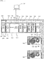
- FIG. 1 is a schematic diagram showing an entire configuration of an automatic analysis system according to an embodiment of the invention.
- the automatic analysis system according to the present embodiment includes an introducing unit 110, a conveyance unit 120, a centrifugal unit 140, a cap opening unit 150, a secondary-sample container preparation unit 160, a dispensing unit 170, a cap closing unit 180, a housing unit 130, a plurality of analysis devices 190, an operation unit 101 and a storage cabinet 210.
- the introducing unit 110 introduces a sample container 200 (test tube) storing a sample (specimen) such as blood or urine into the automatic analysis system.
- a sample recognition unit 121, a cap body detection unit 122, and a carrier recognition unit 125 are provided in the introducing unit 110.
- the sample recognition unit 121 reads a barcode attached to the sample container 200 and identifies a sample to be conveyed.
- the cap body detection unit 122 captures an image of the sample container 200, analyzes the captured image, and identifies the type of the sample container 200 and the presence or absence of a cap body and the type of the cap body.
- the carrier recognition unit 125 reads ID information applied to a carrier holding the sample container 200.
- Carrier recognition units 135, ..., 175, 185, and 215 corresponding to the carrier recognition unit 125 are provided in units in the automatic analysis system.
- the conveyance unit 120 is a mechanism that conveys the sample container 200 introduced from the introducing unit 110 and a sample container (secondary container) dispensed in the dispensing unit 170 to units such as the centrifugal unit 140, the dispensing unit 170 and the analysis devices 190.
- the centrifugal unit 140 centrifuges the introduced sample container 200 and separates the sample into a serum component and a blood clot component.
- the cap opening unit 150 opens the cap body from the introduced sample container 200.
- the secondary-sample container preparation unit 160 prepares matters necessary for dispensing the sample stored in the introduced sample container 200 into the subsequent dispensing unit 170, for example, another sample container (secondary container), and attaches a barcode label or the like to the prepared sample container 200.
- the dispensing unit 170 parcels out the centrifugally separated serum component into other empty sample containers (secondary containers) for analysis by the analysis devices 190 described later.
- the cap closing unit 180 closes the treated sample container 200 and the secondary container.
- the housing unit 130 houses the sample container 200 and the secondary container closed by the cap closing unit 180.
- the analysis devices 190 are conveyance destinations of the samples treated in the units in the automatic analysis system, and correct and quantitatively analyze components of the samples.
- Each of the analysis devices 190 includes a sample dispensing mechanism 191, a reagent dispensing mechanism 192, a reagent disk 193, a reaction disk 194, a detection mechanism 195, and a conveyance line 196 that constitutes a part of the conveyance unit 120.
- the sample dispensing mechanism 191 aspirates and discharges the sample in the sample container 200.
- the reagent disk 193 stores a reagent required for component analysis of the sample.
- the reagent dispensing mechanism 192 aspirates and discharges the reagent.
- the detection mechanism 195 measures optical properties of a mixture in a reaction cell of the reaction disk 194 and transmits measured data to the operation unit 101.
- the operation unit 101 includes a processor such as a central processing unit (CPU), a storage device, a communication device, an input device, a display device, and the like.
- the operation unit 101 controls operations of the units in the automatic analysis system, and analyzes measurement data in the analysis devices 190.
- the operation unit 101 may have a function of transmitting an instruction for executing operations related to pretreatment units such as the introducing unit 110, the conveyance unit 120 and the centrifugal unit 140 described above, and the storage cabinet 210.
- the operations of the units in the automatic analysis system may be controlled by the operation units 101 that are separately provided for the analysis devices 190 and for the pretreatment units.
- the storage cabinet 210 refrigerates and stores a quality control sample and a pooled serum after a preparation processing (hereinafter, referred to as the "quality control sample").
- a quality control is performed in order to keep the accuracy of an analysis result of each of the analysis devices 190 at a certain level or more.
- a rule is registered in advance in each of the analysis devices 190.
- An agreement regarding a time interval for implementing the quality control can be considered as the rule, for example, the quality control is implemented every two hours.
- an agreement on the number of measurements of a general sample which is a condition for implementing the quality control also can be considered as another rule, for example, the quality control is implemented every time 100 general samples are measured.
- information for identifying the type of the quality control sample is also included in the rule.
- the rule registered in advance is not necessarily the same for each analysis device 190, and may be set differently.
- the analysis devices 190 are connected in the automatic analysis system according to the present embodiment, and when there are many general samples to be measured, the analysis devices 190 execute the same test. At this time, since the analysis devices 190 usually start a measurement processing almost at the same time, a timing at which the quality control is required may be almost the same. Therefore, if an operator individually introduces the quality control sample to each of the automatic analysis devices as in the related art, it is difficult to introduce a large number of quality control samples almost at the same time, and time required for the quality control is long. However, according to the present embodiment, since the operation unit 101 operates the storage cabinet 210 in accordance with the rule registered in advance for each of the analysis devices 190 to automatically convey the quality control sample to a predetermined analysis device, the time required for the quality control can be reduced.
- the storage cabinet 210 according to the present embodiment is a common storage cabinet that stores the quality control sample that may be supplied to the analysis devices 190.
- FIG. 2 is a plan view showing a configuration of the storage cabinet 210 according to the present embodiment.
- the storage cabinet 210 according to the present embodiment includes a quality control sample tray 210A that can set a large number of the sample containers 200, and a discard box 210B for discarding the quality control sample that is unusable on a basis of the sample containers 200.
- the sample container 200 stored in the storage cabinet 210 has a one-dimensional barcode, an RFID tag on which an identification code is recorded, or the like, so that the internal quality control sample can be identified.
- the storage cabinet 210 can efficiently store the quality control sample that may be supplied to the analysis devices 190 in one place.
- a large number of quality control samples may be required for one analysis device 190 depending on the type of the quality control, and this case can be dealt with when a large number of the quality control samples are provided in the dedicated storage cabinet 210 as in the present embodiment.
- a plurality of the storage cabinets 210 may be provided, and the storage cabinets 210 may supply the quality control samples to the analysis devices 190. Accordingly, even when no large storage cabinet 210 is provided, a certain number of quality control samples can be stored by combining the plurality of the storage cabinets 210. In addition, when the quality control samples are conveyed from one storage cabinet 210 to the analysis devices 190 at the same time, there is a possibility that the conveyance unit 120 downstream of the storage cabinet 210 is congested and the conveyance is difficult.
- the quality control samples are conveyed from the storage cabinets 210 to the respective analysis devices 190 in such a manner that each of the storage cabinets 210 does not overlap with conveyance paths of other storage cabinets 210, the congestion of the conveyance unit 120 can be alleviated, and the time required for the quality control can be reduced.
- FIG. 3 is a flowchart showing operations in an automatic analysis system according to a first embodiment.
- the operator fills the sample containers 200 with the quality control sample, and sets the sample containers 200 in the quality control sample tray 210A of the storage cabinet 210.
- the number and setting positions of the quality control samples to be set are registered in advance by the operation unit 101, and the operator performs an operation according to a registered content.
- the analysis devices 190 notify the operation unit 101 of information that is a trigger of the quality control as quality control sample request information based on the rule registered in advance in the analysis devices 190 (step S101). At this time, the operation unit 101 waits for 10 minutes after receiving a first quality control request information so that the same type of quality control request information can be received from other analysis devices 190, and determines whether one quality control sample can be used for the quality control of the plurality of analysis devices 190. A request waiting time during which the operation unit 101 waits for quality control requests from the plurality of analysis devices 190 can be set by the operation unit 101 for each type of quality control (see FIG. 4 ).
- the operation unit 101 instructs the storage cabinet 210 to take out the target sample container 200 filled with the quality control sample based on the quality control request information from the analysis device 190 (step S102).
- the storage cabinet 210 receives the instruction and takes out the target sample container 200, and the conveyance unit 120 conveys the sample container 200 (quality control sample) to the analysis device 190 that notifies of the request (step S103). Further, the analysis device 190 measures the conveyed quality control sample.
- the quality control sample used for the quality control in one analysis device 190 is sequentially conveyed to other analysis devices 190 by the conveyance unit 120, and is also used for the measurements by other analysis devices 190. Therefore, it is not necessary to individually introduce the quality control sample to each of the analysis devices 190.
- the operator needs to individually introduce the quality control sample to each of the analysis devices even for the same type of quality control, and thus according to the first embodiment, it is possible to reduce the operation of the operator.
- the conveyance unit 120 returns the quality control sample from the analysis device 190 to the storage cabinet 210 (step S104).
- the storage cabinet 210 notifies the operation unit 101 that the quality control sample reached (step S105).
- the operation unit 101 refers to a table registered in advance and confirms whether parameters satisfy conditions. When all the conditions are satisfied, the operation unit 101 instructs the storage cabinet 210 to store the quality control sample in the storage cabinet 210 (step S106). The operation unit 101 also confirms a remaining volume of the quality control sample, and when the remaining volume is small, the operation unit 101 instructs the storage cabinet 210 to, for example, discard the quality control sample into the discard box 210B.
- the operation unit 101 counts parameters such as elapsed time since the quality control sample is first set in the storage cabinet 210 (storage time), the number of times the quality control sample is taken out from the storage cabinet 210 (the number of usages), and time during which the quality control sample is taken out from the storage cabinet 210 (usage time). Further, when one quality control sample is used for the measurements by the plurality of analysis devices 190 when the quality control sample is taken out from the storage cabinet 210 and then is returned to the storage cabinet 210, the parameters are counted multiple times.
- FIG. 4 is a diagram showing the table related to storage conditions of the quality control sample.
- a maximum storage time, a maximum usage time, a maximum number of usages and the like are registered for each type of quality control sample.
- the maximum storage time indicates an upper limit on time during which the quality control sample can be stored in the storage cabinet 210.
- the maximum usage time indicates an upper limit on time during which the quality of the quality control sample can be ensured even when the quality control sample is placed in a normal temperature environment. When the time during which the quality control sample is placed in the normal temperature environment with one usage is almost constant, the maximum number of usages may be used instead of the maximum usage time.
- the maximum usage time of 20 minutes corresponds to the maximum number of usages of 4 times. Considering that a risk of contamination increases with the measurement of the quality control sample, the maximum number of usage may be set separately from the maximum usage time.
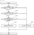
- FIG. 5 is a flowchart showing steps for determining whether to store the quality control sample.
- the operation unit 101 compares time during which the quality control sample is refrigerated and stored in the storage cabinet 210 with the maximum storage time (step S201). When the time exceeds the maximum storage time, the operation unit 101 instructs the storage cabinet 210 to convey the quality control sample to the housing unit 130 (step S205) .
- the operation unit 101 may instruct the storage cabinet 210 to discard the quality control sample into the discard box 210B instead of conveying the quality control sample to the housing unit 130.
- the conveyance unit 120 is used.
- the operation unit 101 compares counted usage time with the maximum usage time (step S202). When the counted usage time exceeds the maximum usage time, the operation unit 101 instructs the storage cabinet 210 to convey the quality control sample to the housing unit 130 or to discard the quality control sample into the discard box 210B (step S205).
- the operation unit 101 compares the counted number of usages with the maximum number of usages (step S203). When the counted number of usages exceeds the maximum number of usages, the operation unit 101 instructs the storage cabinet 210 to convey the quality control sample to the housing unit 130 or to discard the quality control sample into the discard box 210B (step S205). When the counted number of usages is within the maximum number of usages, the operation unit 101 instructs the storage cabinet 210 to store the quality control sample (step S204).
- the quality control sample when at least one of the maximum storage time of the quality control sample, the maximum usage time of the quality control sample and the maximum number of usages of the quality control sample is exceeded, the quality control sample is set to be not stored, and thus it is possible to ensure the accuracy of the quality control at a certain level or more.
- the operation unit 101 ensures the quality of the quality control sample by checking a quality control sample that exceeds the maximum storage time at confirmation intervals of a predetermined time. As a result of the check, when there is a quality control sample that exceeds the maximum storage time, the storage cabinet 210 conveys the quality control sample to the housing unit 130, or discards the quality control sample into the discard box 210B.
- the quality control samples that were measured by the analysis devices are left in the housing units of the analysis devices at room temperature, and thus the operator needs to discard a quality control sample that deteriorates due to a long leaving period and reintroduce another quality control sample.
- the quality control sample that was measured by the analysis device 190 is returned to the storage cabinet 210 and is refrigerated and stored, and thus the time during which the quality control sample is placed in the normal temperature environment is less, and the quality control sample can be used for repeated measurements.
- the quality control sample instead of storing all the quality control samples returned to the storage cabinet 210, the quality control sample is stored only when a predetermined condition is satisfied, and thus the quality of the quality control sample can be ensured.
- the analysis device 190 notifies the operation unit 101 of the quality control request information at a predetermined timing according to the rule registered in the analysis device 190 itself.
- the rules of the analysis devices 190 may be aggregated in advance in the operation unit 101, and the operation unit 101 may issue an instruction to the storage cabinet 210 to convey the quality control sample without the notification from the analysis device 190.
- the quality control sample is sequentially conveyed to the different analysis devices 190 as in the first embodiment and the conveyance unit 120 is congested, it may take time to convey the quality control sample that was measured by a first analysis device 190 to second and subsequent analysis devices 190. Therefore, unlike in the first embodiment, in the second embodiment, the quality control sample is dispensed into other empty sample containers 200 by the dispensing unit 170, and the dispensed samples are individually conveyed to the different analysis devices 190.
- FIG. 6 is a flowchart showing operations in an automatic analysis system according to the second embodiment.
- each of the analysis devices 190 notifies the operation unit 101 of the quality control sample request information based on the rule registered in advance in the analysis device 190 itself (step S301).
- the operation unit 101 instructs the storage cabinet 210 to take out the target quality control sample (step S302).
- the storage cabinet 210 receives the instruction and takes out the target quality control sample, and the conveyance unit 120 conveys the quality control sample to the dispensing unit 170 (step S303).
- the dispensing unit 170 dispenses the quality control sample to other empty sample containers 200 different from the sample container that is filled with the conveyed quality control sample.
- a barcode label is attached to each of the empty sample containers 200 by the secondary-sample container preparation unit 160.
- Information indicating that the sample is the dispensed quality control sample, information on the quality control sample that is the dispensing source and the like are recorded on the barcode label as the one-dimensional barcode.
- attribute information by which the operator can identify the sample as the quality control sample is recorded on the barcode label with characters or the like.
- the quality control sample that is the dispensing source is conveyed to the storage cabinet 210 by the conveyance unit 120 (step S304).
- the storage cabinet 210 notifies the operation unit 101 that the quality control sample reached (step S306).
- the operation unit 101 refers to the table registered in advance and instructs the storage cabinet 210 to store the quality control sample in the storage cabinet 210 when the parameters satisfy the conditions (step S307).
- the dispensed sample is conveyed by the conveyance unit 120 to the analysis device 190 that transmitted the quality control request information (step S305).
- the conveyance unit 120 returns the dispensed sample from the analysis device 190 to the storage cabinet 210 (step S308).
- the dispensed sample may also be sequentially conveyed to the plurality of analysis devices 190 and be used for the measurement by each of the analysis devices 190.
- the storage cabinet 210 notifies the operation unit 101 that the dispensed sample reached (step S309).
- the operation unit 101 refers to the table registered in advance and instructs the storage cabinet 210 to store the dispensed sample in the storage cabinet 210 when the parameters satisfy the conditions (step S310).
- the quality control sample can be dispensed by the dispensing unit 170 and the dispensed samples can be conveyed to the analysis devices 190, and thus an increase in the time required for the quality control due to the congestion of the conveyance unit 120 can be prevented.
- the dispensed samples are set to be stored in the storage cabinet 210 only when the predetermined condition is satisfied, and thus the accuracy of the quality control can also be ensured.
- the dispensed sample is usually produced in the number used by the target analysis device 190. Accordingly, even when the dispensed sample is returned to the storage cabinet 210, the remaining volume is insufficient, and the dispensed sample will be discarded into the discard box 210B or be conveyed to the housing unit 130. However, it is desirable to temporarily store the dispensed sample in the storage cabinet 210 until the measurement of the quality control sample by the analysis device 190 is completed and the measurement data is obtained. A reason is that when the result of the quality control is inappropriate, it would be determined whether the quality control sample is inappropriate or the analysis device 190 is inappropriate.
- the quality control sample including the dispensed sample that is returned to the storage cabinet 210 is to be discarded or the like, the quality control sample is temporarily stored in the storage cabinet 210, and the operation unit 101 waits until the result of the quality control is obtained.
- the analysis device 190 notifies the operation unit 101 that the result of the quality control was obtained (step S311), the operation unit 101 instructs the storage cabinet 210 to discard the quality control sample that is temporarily stored, or the like, and the storage cabinet 210 conveys the quality control sample to the housing unit 130 or discards the quality control sample into the discard box 210B.
- first and second embodiments have been described in detail for easy understanding of the invention, and the invention is not necessarily limited to those including all the configurations described above.
- a part of a configuration of one embodiment may be replaced with a configuration of another embodiment, and a configuration of one embodiment may also be added with a configuration of another embodiment.
- a part of a configuration of each embodiment may be added or replaced with another configuration, and another configuration may be deleted from the configuration of each embodiment.
Landscapes
- Physics & Mathematics (AREA)
- Health & Medical Sciences (AREA)
- Life Sciences & Earth Sciences (AREA)
- Chemical & Material Sciences (AREA)
- Analytical Chemistry (AREA)
- Biochemistry (AREA)
- General Health & Medical Sciences (AREA)
- General Physics & Mathematics (AREA)
- Immunology (AREA)
- Pathology (AREA)
- Engineering & Computer Science (AREA)
- Quality & Reliability (AREA)
- Automatic Analysis And Handling Materials Therefor (AREA)
Abstract
Description
- The present invention relates to an automatic analysis system in which a plurality of analysis devices are connected.
- In an automatic analysis device, a reagent that specifically reacts with a specific component contained in a sample such as blood or urine is added to and reacted with the sample, and an absorbance, a luminescence amount and the like of a reaction solution are measured to perform a qualitative and quantitative analysis.
- In such an automatic analysis device, in order to ensure reliability of an analysis result, a calibration which is a calibration curve calibration operation for obtaining a calibration curve, a quality control for confirming that the calibration curve is appropriate and the like are implemented as necessary. However, there are many types of methods and samples to be used (calibration sample, quality control sample), and handling and management are complicated.
- In addition, the following techniques are known for the handling and management of the quality control sample. For example,
PTL 1 describes that in an automatic analysis device to which a plurality of functional modules are connected, a cold insulation unit that stores a quality control sample is provided in each of the modules, and the quality control sample is used in the modules as necessary. Further,PTL 2 describes an automatic analysis device that performs a preparation processing such that a quality control sample can be used at a preset time and is provided with a storage unit that stores the quality control sample after the preparation processing. -
- PTL 1:
JP-A-2015-57617 - PTL 2:
JP-A-2015-135282 - In an automatic analysis system in the related art such as
PTL 1 andPTL 2 described above, an operator introduces the quality control sample to the modules, and overall operational time required for a quality control is lengthened. In particular, a large number of quality control samples may be required depending on a type of quality control, and it is difficult to store a large number of quality control samples in the modules and for the operator to introduce the quality control samples. - An object of the invention is to provide an automatic analysis system that reduces time required for a quality control even when a large number of quality control samples are required.
- In order to achieve the above object, the invention provides an automatic analysis system that includes a plurality of analysis devices, a conveyance unit to which the analysis devices are connected, and an operation unit configured to operate the conveyance unit and convey a sample to the analysis devices. The automatic analysis system includes a common storage cabinet that stores a quality control sample that is suppliable to the plurality of analysis devices, and in accordance with a rule registered in advance for each of the plurality of analysis devices, the operation unit operates the storage cabinet to automatically convey the quality control sample to the analysis device.
- According to the invention, an automatic analysis system that reduces time required for a quality control even when a large number of quality control samples are required can be provided.
-
- [
FIG. 1] FIG. 1 is a schematic diagram showing an entire configuration of an automatic analysis system according to an embodiment. - [
FIG. 2] FIG. 2 is a plan view showing a configuration of a storage cabinet according to the embodiment. - [
FIG. 3] FIG. 3 is a flowchart showing operations in an automatic analysis system according to a first embodiment. - [
FIG. 4] FIG. 4 is a diagram showing a table related to storage conditions of a quality control sample. - [
FIG. 5] FIG. 5 is a flowchart showing steps for determining whether to store the quality control sample. - [
FIG. 6] FIG. 6 is a flowchart showing operations in an automatic analysis system according to a second embodiment. -
FIG. 1 is a schematic diagram showing an entire configuration of an automatic analysis system according to an embodiment of the invention. As shown inFIG. 1 , the automatic analysis system according to the present embodiment includes an introducingunit 110, aconveyance unit 120, acentrifugal unit 140, acap opening unit 150, a secondary-samplecontainer preparation unit 160, adispensing unit 170, acap closing unit 180, ahousing unit 130, a plurality ofanalysis devices 190, anoperation unit 101 and astorage cabinet 210. - Here, the introducing
unit 110 introduces a sample container 200 (test tube) storing a sample (specimen) such as blood or urine into the automatic analysis system. Asample recognition unit 121, a capbody detection unit 122, and acarrier recognition unit 125 are provided in the introducingunit 110. Thesample recognition unit 121 reads a barcode attached to thesample container 200 and identifies a sample to be conveyed. The capbody detection unit 122 captures an image of thesample container 200, analyzes the captured image, and identifies the type of thesample container 200 and the presence or absence of a cap body and the type of the cap body. Thecarrier recognition unit 125 reads ID information applied to a carrier holding thesample container 200.Carrier recognition units 135, ..., 175, 185, and 215 corresponding to thecarrier recognition unit 125 are provided in units in the automatic analysis system. - Next, the
conveyance unit 120 is a mechanism that conveys thesample container 200 introduced from the introducingunit 110 and a sample container (secondary container) dispensed in thedispensing unit 170 to units such as thecentrifugal unit 140, thedispensing unit 170 and theanalysis devices 190. Thecentrifugal unit 140 centrifuges the introducedsample container 200 and separates the sample into a serum component and a blood clot component. Thecap opening unit 150 opens the cap body from the introducedsample container 200. The secondary-samplecontainer preparation unit 160 prepares matters necessary for dispensing the sample stored in the introducedsample container 200 into thesubsequent dispensing unit 170, for example, another sample container (secondary container), and attaches a barcode label or the like to the preparedsample container 200. The dispensingunit 170 parcels out the centrifugally separated serum component into other empty sample containers (secondary containers) for analysis by theanalysis devices 190 described later. Thecap closing unit 180 closes the treatedsample container 200 and the secondary container. Thehousing unit 130 houses thesample container 200 and the secondary container closed by thecap closing unit 180. - The
analysis devices 190 are conveyance destinations of the samples treated in the units in the automatic analysis system, and correct and quantitatively analyze components of the samples. Each of theanalysis devices 190 includes asample dispensing mechanism 191, areagent dispensing mechanism 192, areagent disk 193, areaction disk 194, adetection mechanism 195, and aconveyance line 196 that constitutes a part of theconveyance unit 120. - Here, the
sample dispensing mechanism 191 aspirates and discharges the sample in thesample container 200. Thereagent disk 193 stores a reagent required for component analysis of the sample. In addition, thereagent dispensing mechanism 192 aspirates and discharges the reagent. Thedetection mechanism 195 measures optical properties of a mixture in a reaction cell of thereaction disk 194 and transmits measured data to theoperation unit 101. - The
operation unit 101 includes a processor such as a central processing unit (CPU), a storage device, a communication device, an input device, a display device, and the like. Theoperation unit 101 controls operations of the units in the automatic analysis system, and analyzes measurement data in theanalysis devices 190. In particular, regarding the control of the operations of the units in the automatic analysis system, for example, as specifically shown inFIG. 6 , theoperation unit 101 may have a function of transmitting an instruction for executing operations related to pretreatment units such as the introducingunit 110, theconveyance unit 120 and thecentrifugal unit 140 described above, and thestorage cabinet 210. Further, for example, when the number ofanalysis devices 190 is large, the operations of the units in the automatic analysis system may be controlled by theoperation units 101 that are separately provided for theanalysis devices 190 and for the pretreatment units. - Apart from a cold insulation cabinet for the reagent required for the analysis, the
storage cabinet 210 refrigerates and stores a quality control sample and a pooled serum after a preparation processing (hereinafter, referred to as the "quality control sample"). - In the automatic analysis system according to the present embodiment, a quality control is performed in order to keep the accuracy of an analysis result of each of the
analysis devices 190 at a certain level or more. Here, regarding under what conditions the quality control is executed, a rule is registered in advance in each of theanalysis devices 190. An agreement regarding a time interval for implementing the quality control can be considered as the rule, for example, the quality control is implemented every two hours. In addition, an agreement on the number of measurements of a general sample which is a condition for implementing the quality control also can be considered as another rule, for example, the quality control is implemented every time 100 general samples are measured. Further, when there are plural numbers of types of samples used for the quality control, information for identifying the type of the quality control sample is also included in the rule. The rule registered in advance is not necessarily the same for eachanalysis device 190, and may be set differently. - The
analysis devices 190 are connected in the automatic analysis system according to the present embodiment, and when there are many general samples to be measured, theanalysis devices 190 execute the same test. At this time, since theanalysis devices 190 usually start a measurement processing almost at the same time, a timing at which the quality control is required may be almost the same. Therefore, if an operator individually introduces the quality control sample to each of the automatic analysis devices as in the related art, it is difficult to introduce a large number of quality control samples almost at the same time, and time required for the quality control is long. However, according to the present embodiment, since theoperation unit 101 operates thestorage cabinet 210 in accordance with the rule registered in advance for each of theanalysis devices 190 to automatically convey the quality control sample to a predetermined analysis device, the time required for the quality control can be reduced. - Here, the
storage cabinet 210 according to the present embodiment is a common storage cabinet that stores the quality control sample that may be supplied to theanalysis devices 190.FIG. 2 is a plan view showing a configuration of thestorage cabinet 210 according to the present embodiment. As shown inFIG. 2 , thestorage cabinet 210 according to the present embodiment includes a qualitycontrol sample tray 210A that can set a large number of thesample containers 200, and a discardbox 210B for discarding the quality control sample that is unusable on a basis of thesample containers 200. In addition, thesample container 200 stored in thestorage cabinet 210 has a one-dimensional barcode, an RFID tag on which an identification code is recorded, or the like, so that the internal quality control sample can be identified. - When each of the
analysis devices 190 is provided with an individual storage cabinet, it is difficult to provide a space where a large storage cabinet is disposed in each of theanalysis devices 190. Accordingly, the number of the quality control samples that can be stored is inevitably limited. In contrast, thestorage cabinet 210 according to the present embodiment can efficiently store the quality control sample that may be supplied to theanalysis devices 190 in one place. In particular, a large number of quality control samples may be required for oneanalysis device 190 depending on the type of the quality control, and this case can be dealt with when a large number of the quality control samples are provided in thededicated storage cabinet 210 as in the present embodiment. - When a large number of quality control samples are required to be introduced, a plurality of the
storage cabinets 210 may be provided, and thestorage cabinets 210 may supply the quality control samples to theanalysis devices 190. Accordingly, even when nolarge storage cabinet 210 is provided, a certain number of quality control samples can be stored by combining the plurality of thestorage cabinets 210. In addition, when the quality control samples are conveyed from onestorage cabinet 210 to theanalysis devices 190 at the same time, there is a possibility that theconveyance unit 120 downstream of thestorage cabinet 210 is congested and the conveyance is difficult. However, if the quality control samples are conveyed from thestorage cabinets 210 to therespective analysis devices 190 in such a manner that each of thestorage cabinets 210 does not overlap with conveyance paths ofother storage cabinets 210, the congestion of theconveyance unit 120 can be alleviated, and the time required for the quality control can be reduced. - Next, operations of the automatic analysis system according to the present embodiment will be described.
-
FIG. 3 is a flowchart showing operations in an automatic analysis system according to a first embodiment. First, the operator fills thesample containers 200 with the quality control sample, and sets thesample containers 200 in the qualitycontrol sample tray 210A of thestorage cabinet 210. The number and setting positions of the quality control samples to be set are registered in advance by theoperation unit 101, and the operator performs an operation according to a registered content. - The
analysis devices 190 notify theoperation unit 101 of information that is a trigger of the quality control as quality control sample request information based on the rule registered in advance in the analysis devices 190 (step S101). At this time, theoperation unit 101 waits for 10 minutes after receiving a first quality control request information so that the same type of quality control request information can be received fromother analysis devices 190, and determines whether one quality control sample can be used for the quality control of the plurality ofanalysis devices 190. A request waiting time during which theoperation unit 101 waits for quality control requests from the plurality ofanalysis devices 190 can be set by theoperation unit 101 for each type of quality control (seeFIG. 4 ). - When the request waiting time elapses, the
operation unit 101 instructs thestorage cabinet 210 to take out thetarget sample container 200 filled with the quality control sample based on the quality control request information from the analysis device 190 (step S102). Thestorage cabinet 210 receives the instruction and takes out thetarget sample container 200, and theconveyance unit 120 conveys the sample container 200 (quality control sample) to theanalysis device 190 that notifies of the request (step S103). Further, theanalysis device 190 measures the conveyed quality control sample. - When the
operation unit 101 also receives the same type of request fromother analysis devices 190, the quality control sample used for the quality control in oneanalysis device 190 is sequentially conveyed toother analysis devices 190 by theconveyance unit 120, and is also used for the measurements byother analysis devices 190. Therefore, it is not necessary to individually introduce the quality control sample to each of theanalysis devices 190. Here, in an automatic analysis system in the related art, the operator needs to individually introduce the quality control sample to each of the analysis devices even for the same type of quality control, and thus according to the first embodiment, it is possible to reduce the operation of the operator. - Further, when the measurement by the
analysis device 190 is completed, theconveyance unit 120 returns the quality control sample from theanalysis device 190 to the storage cabinet 210 (step S104). When the quality control sample reaches thestorage cabinet 210, thestorage cabinet 210 notifies theoperation unit 101 that the quality control sample reached (step S105). - Regarding the quality control sample returned to the
storage cabinet 210, theoperation unit 101 refers to a table registered in advance and confirms whether parameters satisfy conditions. When all the conditions are satisfied, theoperation unit 101 instructs thestorage cabinet 210 to store the quality control sample in the storage cabinet 210 (step S106). Theoperation unit 101 also confirms a remaining volume of the quality control sample, and when the remaining volume is small, theoperation unit 101 instructs thestorage cabinet 210 to, for example, discard the quality control sample into the discardbox 210B. - Here, for each of the quality control samples, the
operation unit 101 counts parameters such as elapsed time since the quality control sample is first set in the storage cabinet 210 (storage time), the number of times the quality control sample is taken out from the storage cabinet 210 (the number of usages), and time during which the quality control sample is taken out from the storage cabinet 210 (usage time). Further, when one quality control sample is used for the measurements by the plurality ofanalysis devices 190 when the quality control sample is taken out from thestorage cabinet 210 and then is returned to thestorage cabinet 210, the parameters are counted multiple times. -
FIG. 4 is a diagram showing the table related to storage conditions of the quality control sample. In the table, a maximum storage time, a maximum usage time, a maximum number of usages and the like are registered for each type of quality control sample. The maximum storage time indicates an upper limit on time during which the quality control sample can be stored in thestorage cabinet 210. The maximum usage time indicates an upper limit on time during which the quality of the quality control sample can be ensured even when the quality control sample is placed in a normal temperature environment. When the time during which the quality control sample is placed in the normal temperature environment with one usage is almost constant, the maximum number of usages may be used instead of the maximum usage time. For example, when the time required for the quality control sample to be conveyed from thestorage cabinet 210 and be returned to thestorage cabinet 210 after passing though the plurality ofanalysis devices 190 is 5 minutes, the maximum usage time of 20 minutes corresponds to the maximum number of usages of 4 times. Considering that a risk of contamination increases with the measurement of the quality control sample, the maximum number of usage may be set separately from the maximum usage time. -
FIG. 5 is a flowchart showing steps for determining whether to store the quality control sample. As shown inFIG. 5 , regarding the quality control sample returned to thestorage cabinet 210, theoperation unit 101 compares time during which the quality control sample is refrigerated and stored in thestorage cabinet 210 with the maximum storage time (step S201). When the time exceeds the maximum storage time, theoperation unit 101 instructs thestorage cabinet 210 to convey the quality control sample to the housing unit 130 (step S205) . Theoperation unit 101 may instruct thestorage cabinet 210 to discard the quality control sample into the discardbox 210B instead of conveying the quality control sample to thehousing unit 130. When the quality control sample is conveyed from thestorage cabinet 210 to thehousing unit 130, theconveyance unit 120 is used. - When the time is within the maximum storage time, the
operation unit 101 compares counted usage time with the maximum usage time (step S202). When the counted usage time exceeds the maximum usage time, theoperation unit 101 instructs thestorage cabinet 210 to convey the quality control sample to thehousing unit 130 or to discard the quality control sample into the discardbox 210B (step S205). - When the counted usage time is within the maximum usage time, the
operation unit 101 compares the counted number of usages with the maximum number of usages (step S203). When the counted number of usages exceeds the maximum number of usages, theoperation unit 101 instructs thestorage cabinet 210 to convey the quality control sample to thehousing unit 130 or to discard the quality control sample into the discardbox 210B (step S205). When the counted number of usages is within the maximum number of usages, theoperation unit 101 instructs thestorage cabinet 210 to store the quality control sample (step S204). - In this way, in the first embodiment, when at least one of the maximum storage time of the quality control sample, the maximum usage time of the quality control sample and the maximum number of usages of the quality control sample is exceeded, the quality control sample is set to be not stored, and thus it is possible to ensure the accuracy of the quality control at a certain level or more.
- In the automatic analysis system according to the first embodiment, even when a quality control sample request is not notified of by the
analysis device 190, theoperation unit 101 ensures the quality of the quality control sample by checking a quality control sample that exceeds the maximum storage time at confirmation intervals of a predetermined time. As a result of the check, when there is a quality control sample that exceeds the maximum storage time, thestorage cabinet 210 conveys the quality control sample to thehousing unit 130, or discards the quality control sample into the discardbox 210B. - Here, in the automatic analysis system in the related art, the quality control samples that were measured by the analysis devices are left in the housing units of the analysis devices at room temperature, and thus the operator needs to discard a quality control sample that deteriorates due to a long leaving period and reintroduce another quality control sample. However, according to the first embodiment, the quality control sample that was measured by the
analysis device 190 is returned to thestorage cabinet 210 and is refrigerated and stored, and thus the time during which the quality control sample is placed in the normal temperature environment is less, and the quality control sample can be used for repeated measurements. In addition, in the first embodiment, instead of storing all the quality control samples returned to thestorage cabinet 210, the quality control sample is stored only when a predetermined condition is satisfied, and thus the quality of the quality control sample can be ensured. - In the first embodiment, the
analysis device 190 notifies theoperation unit 101 of the quality control request information at a predetermined timing according to the rule registered in theanalysis device 190 itself. The rules of theanalysis devices 190 may be aggregated in advance in theoperation unit 101, and theoperation unit 101 may issue an instruction to thestorage cabinet 210 to convey the quality control sample without the notification from theanalysis device 190. - When one quality control sample is sequentially conveyed to the
different analysis devices 190 as in the first embodiment and theconveyance unit 120 is congested, it may take time to convey the quality control sample that was measured by afirst analysis device 190 to second andsubsequent analysis devices 190. Therefore, unlike in the first embodiment, in the second embodiment, the quality control sample is dispensed into otherempty sample containers 200 by the dispensingunit 170, and the dispensed samples are individually conveyed to thedifferent analysis devices 190. -
FIG. 6 is a flowchart showing operations in an automatic analysis system according to the second embodiment. First, similar to the first embodiment, each of theanalysis devices 190 notifies theoperation unit 101 of the quality control sample request information based on the rule registered in advance in theanalysis device 190 itself (step S301). Next, theoperation unit 101 instructs thestorage cabinet 210 to take out the target quality control sample (step S302). Thestorage cabinet 210 receives the instruction and takes out the target quality control sample, and theconveyance unit 120 conveys the quality control sample to the dispensing unit 170 (step S303). - Further, the dispensing
unit 170 dispenses the quality control sample to otherempty sample containers 200 different from the sample container that is filled with the conveyed quality control sample. A barcode label is attached to each of theempty sample containers 200 by the secondary-samplecontainer preparation unit 160. Information indicating that the sample is the dispensed quality control sample, information on the quality control sample that is the dispensing source and the like are recorded on the barcode label as the one-dimensional barcode. In addition, attribute information by which the operator can identify the sample as the quality control sample is recorded on the barcode label with characters or the like. - Then, the quality control sample that is the dispensing source is conveyed to the
storage cabinet 210 by the conveyance unit 120 (step S304). When the quality control sample that is the dispensing source reaches thestorage cabinet 210, thestorage cabinet 210 notifies theoperation unit 101 that the quality control sample reached (step S306). Next, regarding the quality control sample that is the dispensing source, theoperation unit 101 refers to the table registered in advance and instructs thestorage cabinet 210 to store the quality control sample in thestorage cabinet 210 when the parameters satisfy the conditions (step S307). - On the other hand, the dispensed sample is conveyed by the
conveyance unit 120 to theanalysis device 190 that transmitted the quality control request information (step S305). When the measurement by theanalysis device 190 is completed, theconveyance unit 120 returns the dispensed sample from theanalysis device 190 to the storage cabinet 210 (step S308). Further, the dispensed sample may also be sequentially conveyed to the plurality ofanalysis devices 190 and be used for the measurement by each of theanalysis devices 190. When the dispensed sample reaches thestorage cabinet 210, thestorage cabinet 210 notifies theoperation unit 101 that the dispensed sample reached (step S309). Next, regarding the dispensed sample, theoperation unit 101 refers to the table registered in advance and instructs thestorage cabinet 210 to store the dispensed sample in thestorage cabinet 210 when the parameters satisfy the conditions (step S310). - According to the second embodiment, even when the plurality of
analysis devices 190 notify theoperation unit 101 of the quality control request information almost at the same time, the quality control sample can be dispensed by the dispensingunit 170 and the dispensed samples can be conveyed to theanalysis devices 190, and thus an increase in the time required for the quality control due to the congestion of theconveyance unit 120 can be prevented. In addition, not only the original quality control sample but also the dispensed samples are set to be stored in thestorage cabinet 210 only when the predetermined condition is satisfied, and thus the accuracy of the quality control can also be ensured. - Further, the dispensed sample is usually produced in the number used by the
target analysis device 190. Accordingly, even when the dispensed sample is returned to thestorage cabinet 210, the remaining volume is insufficient, and the dispensed sample will be discarded into the discardbox 210B or be conveyed to thehousing unit 130. However, it is desirable to temporarily store the dispensed sample in thestorage cabinet 210 until the measurement of the quality control sample by theanalysis device 190 is completed and the measurement data is obtained. A reason is that when the result of the quality control is inappropriate, it would be determined whether the quality control sample is inappropriate or theanalysis device 190 is inappropriate. Therefore, even when the quality control sample including the dispensed sample that is returned to thestorage cabinet 210 is to be discarded or the like, the quality control sample is temporarily stored in thestorage cabinet 210, and theoperation unit 101 waits until the result of the quality control is obtained. When theanalysis device 190 notifies theoperation unit 101 that the result of the quality control was obtained (step S311), theoperation unit 101 instructs thestorage cabinet 210 to discard the quality control sample that is temporarily stored, or the like, and thestorage cabinet 210 conveys the quality control sample to thehousing unit 130 or discards the quality control sample into the discardbox 210B. - In addition, the above first and second embodiments have been described in detail for easy understanding of the invention, and the invention is not necessarily limited to those including all the configurations described above. A part of a configuration of one embodiment may be replaced with a configuration of another embodiment, and a configuration of one embodiment may also be added with a configuration of another embodiment. A part of a configuration of each embodiment may be added or replaced with another configuration, and another configuration may be deleted from the configuration of each embodiment.
-
- 101 operation unit
- 110 introducing unit
- 120 conveyance unit
- 121 sample recognition unit
- 122 cap body detection unit
- 125, 135, 175, 185, 215 carrier recognition unit
- 130 housing unit
- 140 centrifugal unit
- 150 cap opening unit
- 160 secondary-sample container preparation unit
- 170 dispensing unit
- 180 cap closing unit
- 190 analysis device
- 191 sample dispensing mechanism
- 192 reagent dispensing mechanism
- 193 reagent disk
- 194 reaction disk
- 195 detection mechanism
- 196 conveyance line
- 200 sample container
- 210 storage cabinet
- 210A quality control sample tray
- 210B discard box
Claims (7)
- An automatic analysis system comprising:a plurality of analysis devices; a conveyance unit to which the analysis devices are connected; and an operation unit configured to operate the conveyance unit to convey a sample to the analysis devices, whereinthe automatic analysis system includes a common storage cabinet that stores a quality control sample that is suppliable to the plurality of analysis devices, andin accordance with a rule registered in advance for each of the plurality of analysis devices, the operation unit operates the storage cabinet to automatically convey the quality control sample to the analysis device.
- The automatic analysis system according to claim 1, wherein
when the analysis device notifies the operation unit of information that is a trigger of a quality control, the operation unit instructs the storage cabinet to take out the quality control sample, and the conveyance unit conveys the quality control sample to the analysis device. - The automatic analysis system according to claim 1, wherein
the rule includes at least one of a type of a sample used for a quality control, a time interval for implementing a quality control, and the number of measurements of a general sample as a condition for implementing a quality control. - The automatic analysis system according to claim 1, whereinthe conveyance unit conveys the quality control sample used in the analysis device into the storage cabinet, andwhen at least one of a maximum storage time of the quality control sample, a maximum usage time of the quality control sample, and a maximum number of usages of the quality control sample is exceeded, the storage cabinet does not store the quality control sample, and discards the quality control sample or conveys the quality control sample to a housing unit outside the storage cabinet.
- The automatic analysis system according to claim 1, further comprising:a dispensing unit configured to dispense the quality control sample, whereina plurality of dispensed samples dispensed by the dispensing unit are conveyed to the different analysis devices.
- The automatic analysis system according to claim 1, further comprising:a dispensing unit configured to dispense the quality control sample, whereina dispensed sample dispensed by the dispensing unit is conveyed to the analysis device, andthe quality control sample that is a dispensing source is conveyed to the storage cabinet, and is stored in the storage cabinet when a predetermined condition is satisfied.
- The automatic analysis system according to claim 1, further comprising:a plurality of the storage cabinets, whereinthe storage cabinets supply the quality control sample to the plurality of analysis devices.
Applications Claiming Priority (2)
| Application Number | Priority Date | Filing Date | Title |
|---|---|---|---|
| JP2020013416 | 2020-01-30 | ||
| PCT/JP2020/046110 WO2021153028A1 (en) | 2020-01-30 | 2020-12-10 | Automatic analysis system |
Publications (2)
| Publication Number | Publication Date |
|---|---|
| EP4099019A1 true EP4099019A1 (en) | 2022-12-07 |
| EP4099019A4 EP4099019A4 (en) | 2024-03-06 |
Family
ID=77078948
Family Applications (1)
| Application Number | Title | Priority Date | Filing Date |
|---|---|---|---|
| EP20917254.3A Pending EP4099019A4 (en) | 2020-01-30 | 2020-12-10 | Automatic analysis system |
Country Status (5)
| Country | Link |
|---|---|
| US (1) | US20230123687A1 (en) |
| EP (1) | EP4099019A4 (en) |
| JP (2) | JP7555171B2 (en) |
| CN (1) | CN114846333B (en) |
| WO (1) | WO2021153028A1 (en) |
Families Citing this family (6)
| Publication number | Priority date | Publication date | Assignee | Title |
|---|---|---|---|---|
| JP7752690B2 (en) * | 2021-09-15 | 2025-10-10 | 株式会社日立ハイテク | Automated Analysis System |
| JP7901171B2 (en) * | 2022-09-06 | 2026-08-05 | 株式会社日立ハイテク | Container storage device, automated analysis system, and sample container removal method |
| JP2024049206A (en) * | 2022-09-28 | 2024-04-09 | アークレイ株式会社 | Accuracy control method, holding tool and measuring device |
| EP4664108A1 (en) * | 2023-02-10 | 2025-12-17 | Hitachi High-Tech Corporation | Container storage device, container storage method, and automatic analysis system |
| CN120693524A (en) * | 2023-04-11 | 2025-09-23 | 株式会社日立高新技术 | Container storage device, analysis system, and container transfer method |
| WO2025197569A1 (en) * | 2024-03-21 | 2025-09-25 | 株式会社日立ハイテク | Automatic analysis system |
Family Cites Families (36)
| Publication number | Priority date | Publication date | Assignee | Title |
|---|---|---|---|---|
| JP2994578B2 (en) * | 1995-07-20 | 1999-12-27 | 株式会社エイアンドティー | Sample transport system |
| DE19714314C1 (en) * | 1997-04-08 | 1998-05-28 | Kali & Salz Beteiligungs Ag | Method of testing valve sealing of filled valve sack |
| EP0871034B1 (en) * | 1997-04-10 | 2007-03-07 | Hitachi, Ltd. | Automatic analyzer and support system therefor |
| JP3889877B2 (en) * | 1997-04-10 | 2007-03-07 | 株式会社日立製作所 | Automatic analyzer and its support system |
| JP3238889B2 (en) * | 1997-10-20 | 2001-12-17 | アロカ株式会社 | Dispensing device |
| JP3931150B2 (en) * | 2003-03-19 | 2007-06-13 | 株式会社日立ハイテクノロジーズ | Automatic analyzer |
| JP3873039B2 (en) * | 2003-05-14 | 2007-01-24 | 株式会社日立ハイテクノロジーズ | Automatic analyzer |
| JP4033060B2 (en) * | 2003-07-17 | 2008-01-16 | 株式会社日立ハイテクノロジーズ | Automatic analyzer |
| US6984527B2 (en) * | 2003-08-11 | 2006-01-10 | Dade Behring Inc. | Automated quality control protocols in a multi-analyzer system |
| US7670553B2 (en) * | 2005-03-24 | 2010-03-02 | Siemens Healthcare Diagnostics Inc. | Carousel system for automated chemical or biological analyzers employing linear racks |
| JP4378336B2 (en) | 2005-09-09 | 2009-12-02 | アロカ株式会社 | Sample pretreatment system and method |
| JP4892001B2 (en) * | 2005-10-03 | 2012-03-07 | ジーイー・アナリティカル・インストルメンツ・インコーポレイテッド | Automatic standard product sampling |
| JP2008058123A (en) * | 2006-08-31 | 2008-03-13 | Hitachi High-Technologies Corp | Automatic analyzer |
| JP2008209338A (en) * | 2007-02-28 | 2008-09-11 | Hitachi High-Technologies Corp | Automatic analyzer |
| JP5179890B2 (en) * | 2007-03-30 | 2013-04-10 | シスメックス株式会社 | Sample analyzer |
| JP2008281453A (en) * | 2007-05-11 | 2008-11-20 | Hitachi High-Technologies Corp | Automatic analysis system |
| JP2009008558A (en) * | 2007-06-28 | 2009-01-15 | A & T Corp | Dispenser, sample inspection system, dispensing method, sample inspection method, dispensing program, and sample inspection program |
| JP5049769B2 (en) * | 2007-12-25 | 2012-10-17 | 株式会社日立ハイテクノロジーズ | Automatic analyzer and sample processing system |
| JP2010121936A (en) * | 2008-10-23 | 2010-06-03 | Sysmex Corp | Specimen processing system |
| US9097690B2 (en) * | 2009-09-30 | 2015-08-04 | Hitachi High-Technologies Corporation | Sample preprocessing and conveying system |
| JP5656852B2 (en) | 2009-09-30 | 2015-01-21 | 株式会社日立ハイテクノロジーズ | Sample pretreatment system |
| WO2011093442A1 (en) * | 2010-01-28 | 2011-08-04 | 株式会社日立ハイテクノロジーズ | Automatic analyzing system |
| JP5340975B2 (en) * | 2010-01-29 | 2013-11-13 | 株式会社日立ハイテクノロジーズ | Automatic analyzer |
| JP5417353B2 (en) * | 2011-01-31 | 2014-02-12 | 株式会社日立ハイテクノロジーズ | Automatic analysis system |
| CN103091287B (en) * | 2011-10-31 | 2015-04-01 | 深圳迈瑞生物医疗电子股份有限公司 | Self-diagnosis method for measure result of blood analyzer, and device thereof |
| CA2802258A1 (en) * | 2012-01-20 | 2013-07-20 | Ortho-Clinical Diagnostics, Inc. | Low volume assay device having increased sensitivity |
| JP5898972B2 (en) * | 2012-01-23 | 2016-04-06 | 株式会社日立ハイテクノロジーズ | Automatic analyzer |
| WO2014110587A1 (en) | 2013-01-14 | 2014-07-17 | Siemens Healthcare Diagnostics Inc. | Test menu expansion system and method |
| JP2015135282A (en) * | 2014-01-17 | 2015-07-27 | 株式会社日立ハイテクノロジーズ | Automatic analyzer |
| JP6403206B2 (en) | 2015-01-28 | 2018-10-10 | 日本電子株式会社 | Automatic analyzer and automatic analysis method |
| JP6518454B2 (en) * | 2015-02-12 | 2019-05-22 | 日本電子株式会社 | Automatic analyzer and automatic analysis method |
| KR20170014689A (en) * | 2015-07-31 | 2017-02-08 | 가톨릭대학교 산학협력단 | Apparatus for automatic quality control of blood cell analyzer |
| CN105181984B (en) | 2015-09-29 | 2017-03-01 | 北京泱深生物信息技术有限公司 | Intelligent specimen reaction analytical equipment |
| EP3217180B1 (en) * | 2016-03-10 | 2021-11-17 | F. Hoffmann-La Roche AG | Quality controls of analyzers for biological samples |
| US11156625B2 (en) * | 2017-03-07 | 2021-10-26 | Hitachi High-Tech Corporation | Automatic analysis device |
| EP3751284B1 (en) * | 2019-06-14 | 2023-02-22 | F. Hoffmann-La Roche AG | Method and laboratory system to provide control samples for validating a diagnostic test |
-
2020
- 2020-12-10 EP EP20917254.3A patent/EP4099019A4/en active Pending
- 2020-12-10 WO PCT/JP2020/046110 patent/WO2021153028A1/en not_active Ceased
- 2020-12-10 JP JP2021574504A patent/JP7555171B2/en active Active
- 2020-12-10 CN CN202080085217.0A patent/CN114846333B/en active Active
- 2020-12-10 US US17/794,543 patent/US20230123687A1/en active Pending
-
2024
- 2024-09-06 JP JP2024153627A patent/JP7760675B2/en active Active
Also Published As
| Publication number | Publication date |
|---|---|
| JPWO2021153028A1 (en) | 2021-08-05 |
| CN114846333A (en) | 2022-08-02 |
| US20230123687A1 (en) | 2023-04-20 |
| JP7760675B2 (en) | 2025-10-27 |
| JP2024170565A (en) | 2024-12-10 |
| WO2021153028A1 (en) | 2021-08-05 |
| JP7555171B2 (en) | 2024-09-24 |
| EP4099019A4 (en) | 2024-03-06 |
| CN114846333B (en) | 2026-06-30 |
Similar Documents
| Publication | Publication Date | Title |
|---|---|---|
| US20230123687A1 (en) | Automatic Analysis System | |
| US11630115B2 (en) | Sample testing system with automated control of sample retesting | |
| JP6132884B2 (en) | Automatic analyzer | |
| US11199559B2 (en) | Automatic analyzer | |
| EP2518514B1 (en) | A method for operating an automated sample workcell | |
| US11860176B2 (en) | Method of operating an analytical laboratory | |
| US9952239B2 (en) | Sample inspection automation system and sample transfer method | |
| US20150044096A1 (en) | Automatic analyzer | |
| US11268971B2 (en) | Automated analyzer | |
| EP1965214A2 (en) | Automatic analyzer | |
| US11486887B2 (en) | Automated analyzer | |
| US20040186360A1 (en) | Automatic analyzer | |
| EP3922996B1 (en) | Automatic analysis device | |
| JP2014142216A (en) | Automatic analysis system and control method | |
| WO2023181515A1 (en) | Automatic analysis system |
Legal Events
| Date | Code | Title | Description |
|---|---|---|---|
| STAA | Information on the status of an ep patent application or granted ep patent |
Free format text: STATUS: THE INTERNATIONAL PUBLICATION HAS BEEN MADE |
|
| PUAI | Public reference made under article 153(3) epc to a published international application that has entered the european phase |
Free format text: ORIGINAL CODE: 0009012 |
|
| STAA | Information on the status of an ep patent application or granted ep patent |
Free format text: STATUS: REQUEST FOR EXAMINATION WAS MADE |
|
| 17P | Request for examination filed |
Effective date: 20220830 |
|
| AK | Designated contracting states |
Kind code of ref document: A1 Designated state(s): AL AT BE BG CH CY CZ DE DK EE ES FI FR GB GR HR HU IE IS IT LI LT LU LV MC MK MT NL NO PL PT RO RS SE SI SK SM TR |
|
| DAV | Request for validation of the european patent (deleted) | ||
| DAX | Request for extension of the european patent (deleted) | ||
| A4 | Supplementary search report drawn up and despatched |
Effective date: 20240201 |
|
| RIC1 | Information provided on ipc code assigned before grant |
Ipc: G01N 35/04 20060101ALI20240126BHEP Ipc: G01N 35/00 20060101AFI20240126BHEP |
|
| STAA | Information on the status of an ep patent application or granted ep patent |
Free format text: STATUS: EXAMINATION IS IN PROGRESS |
|
| 17Q | First examination report despatched |
Effective date: 20251127 |