EP4098932A1 - Réservoir présentant une isolation renforcée combinant des matelas d'isolation thermique ainsi que des microsphères et procédé de fabrication d'un tel réservoir - Google Patents
Réservoir présentant une isolation renforcée combinant des matelas d'isolation thermique ainsi que des microsphères et procédé de fabrication d'un tel réservoir Download PDFInfo
- Publication number
- EP4098932A1 EP4098932A1 EP22172884.3A EP22172884A EP4098932A1 EP 4098932 A1 EP4098932 A1 EP 4098932A1 EP 22172884 A EP22172884 A EP 22172884A EP 4098932 A1 EP4098932 A1 EP 4098932A1
- Authority
- EP
- European Patent Office
- Prior art keywords
- barrier
- thermal insulation
- zone
- microspheres
- tank
- Prior art date
- Legal status (The legal status is an assumption and is not a legal conclusion. Google has not performed a legal analysis and makes no representation as to the accuracy of the status listed.)
- Granted
Links
Images



Classifications
-
- F—MECHANICAL ENGINEERING; LIGHTING; HEATING; WEAPONS; BLASTING
- F17—STORING OR DISTRIBUTING GASES OR LIQUIDS
- F17C—VESSELS FOR CONTAINING OR STORING COMPRESSED, LIQUEFIED OR SOLIDIFIED GASES; FIXED-CAPACITY GAS-HOLDERS; FILLING VESSELS WITH, OR DISCHARGING FROM VESSELS, COMPRESSED, LIQUEFIED, OR SOLIDIFIED GASES
- F17C13/00—Details of vessels or of the filling or discharging of vessels
- F17C13/001—Thermal insulation specially adapted for cryogenic vessels
-
- F—MECHANICAL ENGINEERING; LIGHTING; HEATING; WEAPONS; BLASTING
- F17—STORING OR DISTRIBUTING GASES OR LIQUIDS
- F17C—VESSELS FOR CONTAINING OR STORING COMPRESSED, LIQUEFIED OR SOLIDIFIED GASES; FIXED-CAPACITY GAS-HOLDERS; FILLING VESSELS WITH, OR DISCHARGING FROM VESSELS, COMPRESSED, LIQUEFIED, OR SOLIDIFIED GASES
- F17C3/00—Vessels not under pressure
- F17C3/02—Vessels not under pressure with provision for thermal insulation
- F17C3/04—Vessels not under pressure with provision for thermal insulation by insulating layers
-
- F—MECHANICAL ENGINEERING; LIGHTING; HEATING; WEAPONS; BLASTING
- F17—STORING OR DISTRIBUTING GASES OR LIQUIDS
- F17C—VESSELS FOR CONTAINING OR STORING COMPRESSED, LIQUEFIED OR SOLIDIFIED GASES; FIXED-CAPACITY GAS-HOLDERS; FILLING VESSELS WITH, OR DISCHARGING FROM VESSELS, COMPRESSED, LIQUEFIED, OR SOLIDIFIED GASES
- F17C2201/00—Vessel construction, in particular geometry, arrangement or size
- F17C2201/01—Shape
- F17C2201/0128—Shape spherical or elliptical
-
- F—MECHANICAL ENGINEERING; LIGHTING; HEATING; WEAPONS; BLASTING
- F17—STORING OR DISTRIBUTING GASES OR LIQUIDS
- F17C—VESSELS FOR CONTAINING OR STORING COMPRESSED, LIQUEFIED OR SOLIDIFIED GASES; FIXED-CAPACITY GAS-HOLDERS; FILLING VESSELS WITH, OR DISCHARGING FROM VESSELS, COMPRESSED, LIQUEFIED, OR SOLIDIFIED GASES
- F17C2201/00—Vessel construction, in particular geometry, arrangement or size
- F17C2201/05—Size
- F17C2201/054—Size medium (>1 m3)
-
- F—MECHANICAL ENGINEERING; LIGHTING; HEATING; WEAPONS; BLASTING
- F17—STORING OR DISTRIBUTING GASES OR LIQUIDS
- F17C—VESSELS FOR CONTAINING OR STORING COMPRESSED, LIQUEFIED OR SOLIDIFIED GASES; FIXED-CAPACITY GAS-HOLDERS; FILLING VESSELS WITH, OR DISCHARGING FROM VESSELS, COMPRESSED, LIQUEFIED, OR SOLIDIFIED GASES
- F17C2201/00—Vessel construction, in particular geometry, arrangement or size
- F17C2201/05—Size
- F17C2201/056—Small (<1 m3)
-
- F—MECHANICAL ENGINEERING; LIGHTING; HEATING; WEAPONS; BLASTING
- F17—STORING OR DISTRIBUTING GASES OR LIQUIDS
- F17C—VESSELS FOR CONTAINING OR STORING COMPRESSED, LIQUEFIED OR SOLIDIFIED GASES; FIXED-CAPACITY GAS-HOLDERS; FILLING VESSELS WITH, OR DISCHARGING FROM VESSELS, COMPRESSED, LIQUEFIED, OR SOLIDIFIED GASES
- F17C2203/00—Vessel construction, in particular walls or details thereof
- F17C2203/03—Thermal insulations
- F17C2203/0304—Thermal insulations by solid means
-
- F—MECHANICAL ENGINEERING; LIGHTING; HEATING; WEAPONS; BLASTING
- F17—STORING OR DISTRIBUTING GASES OR LIQUIDS
- F17C—VESSELS FOR CONTAINING OR STORING COMPRESSED, LIQUEFIED OR SOLIDIFIED GASES; FIXED-CAPACITY GAS-HOLDERS; FILLING VESSELS WITH, OR DISCHARGING FROM VESSELS, COMPRESSED, LIQUEFIED, OR SOLIDIFIED GASES
- F17C2203/00—Vessel construction, in particular walls or details thereof
- F17C2203/03—Thermal insulations
- F17C2203/0304—Thermal insulations by solid means
- F17C2203/0308—Radiation shield
- F17C2203/032—Multi-sheet layers
-
- F—MECHANICAL ENGINEERING; LIGHTING; HEATING; WEAPONS; BLASTING
- F17—STORING OR DISTRIBUTING GASES OR LIQUIDS
- F17C—VESSELS FOR CONTAINING OR STORING COMPRESSED, LIQUEFIED OR SOLIDIFIED GASES; FIXED-CAPACITY GAS-HOLDERS; FILLING VESSELS WITH, OR DISCHARGING FROM VESSELS, COMPRESSED, LIQUEFIED, OR SOLIDIFIED GASES
- F17C2203/00—Vessel construction, in particular walls or details thereof
- F17C2203/03—Thermal insulations
- F17C2203/0304—Thermal insulations by solid means
- F17C2203/0325—Aerogel
-
- F—MECHANICAL ENGINEERING; LIGHTING; HEATING; WEAPONS; BLASTING
- F17—STORING OR DISTRIBUTING GASES OR LIQUIDS
- F17C—VESSELS FOR CONTAINING OR STORING COMPRESSED, LIQUEFIED OR SOLIDIFIED GASES; FIXED-CAPACITY GAS-HOLDERS; FILLING VESSELS WITH, OR DISCHARGING FROM VESSELS, COMPRESSED, LIQUEFIED, OR SOLIDIFIED GASES
- F17C2203/00—Vessel construction, in particular walls or details thereof
- F17C2203/03—Thermal insulations
- F17C2203/0304—Thermal insulations by solid means
- F17C2203/0329—Foam
-
- F—MECHANICAL ENGINEERING; LIGHTING; HEATING; WEAPONS; BLASTING
- F17—STORING OR DISTRIBUTING GASES OR LIQUIDS
- F17C—VESSELS FOR CONTAINING OR STORING COMPRESSED, LIQUEFIED OR SOLIDIFIED GASES; FIXED-CAPACITY GAS-HOLDERS; FILLING VESSELS WITH, OR DISCHARGING FROM VESSELS, COMPRESSED, LIQUEFIED, OR SOLIDIFIED GASES
- F17C2203/00—Vessel construction, in particular walls or details thereof
- F17C2203/03—Thermal insulations
- F17C2203/0304—Thermal insulations by solid means
- F17C2203/0337—Granular
-
- F—MECHANICAL ENGINEERING; LIGHTING; HEATING; WEAPONS; BLASTING
- F17—STORING OR DISTRIBUTING GASES OR LIQUIDS
- F17C—VESSELS FOR CONTAINING OR STORING COMPRESSED, LIQUEFIED OR SOLIDIFIED GASES; FIXED-CAPACITY GAS-HOLDERS; FILLING VESSELS WITH, OR DISCHARGING FROM VESSELS, COMPRESSED, LIQUEFIED, OR SOLIDIFIED GASES
- F17C2203/00—Vessel construction, in particular walls or details thereof
- F17C2203/03—Thermal insulations
- F17C2203/0391—Thermal insulations by vacuum
-
- F—MECHANICAL ENGINEERING; LIGHTING; HEATING; WEAPONS; BLASTING
- F17—STORING OR DISTRIBUTING GASES OR LIQUIDS
- F17C—VESSELS FOR CONTAINING OR STORING COMPRESSED, LIQUEFIED OR SOLIDIFIED GASES; FIXED-CAPACITY GAS-HOLDERS; FILLING VESSELS WITH, OR DISCHARGING FROM VESSELS, COMPRESSED, LIQUEFIED, OR SOLIDIFIED GASES
- F17C2203/00—Vessel construction, in particular walls or details thereof
- F17C2203/06—Materials for walls or layers thereof; Properties or structures of walls or their materials
- F17C2203/0602—Wall structures; Special features thereof
- F17C2203/0612—Wall structures
- F17C2203/0626—Multiple walls
- F17C2203/0629—Two walls
-
- F—MECHANICAL ENGINEERING; LIGHTING; HEATING; WEAPONS; BLASTING
- F17—STORING OR DISTRIBUTING GASES OR LIQUIDS
- F17C—VESSELS FOR CONTAINING OR STORING COMPRESSED, LIQUEFIED OR SOLIDIFIED GASES; FIXED-CAPACITY GAS-HOLDERS; FILLING VESSELS WITH, OR DISCHARGING FROM VESSELS, COMPRESSED, LIQUEFIED, OR SOLIDIFIED GASES
- F17C2203/00—Vessel construction, in particular walls or details thereof
- F17C2203/06—Materials for walls or layers thereof; Properties or structures of walls or their materials
- F17C2203/0634—Materials for walls or layers thereof
- F17C2203/0636—Metals
- F17C2203/0646—Aluminium
-
- F—MECHANICAL ENGINEERING; LIGHTING; HEATING; WEAPONS; BLASTING
- F17—STORING OR DISTRIBUTING GASES OR LIQUIDS
- F17C—VESSELS FOR CONTAINING OR STORING COMPRESSED, LIQUEFIED OR SOLIDIFIED GASES; FIXED-CAPACITY GAS-HOLDERS; FILLING VESSELS WITH, OR DISCHARGING FROM VESSELS, COMPRESSED, LIQUEFIED, OR SOLIDIFIED GASES
- F17C2203/00—Vessel construction, in particular walls or details thereof
- F17C2203/06—Materials for walls or layers thereof; Properties or structures of walls or their materials
- F17C2203/068—Special properties of materials for vessel walls
- F17C2203/0685—Special properties of materials for vessel walls flexible
-
- F—MECHANICAL ENGINEERING; LIGHTING; HEATING; WEAPONS; BLASTING
- F17—STORING OR DISTRIBUTING GASES OR LIQUIDS
- F17C—VESSELS FOR CONTAINING OR STORING COMPRESSED, LIQUEFIED OR SOLIDIFIED GASES; FIXED-CAPACITY GAS-HOLDERS; FILLING VESSELS WITH, OR DISCHARGING FROM VESSELS, COMPRESSED, LIQUEFIED, OR SOLIDIFIED GASES
- F17C2203/00—Vessel construction, in particular walls or details thereof
- F17C2203/06—Materials for walls or layers thereof; Properties or structures of walls or their materials
- F17C2203/068—Special properties of materials for vessel walls
- F17C2203/0697—Special properties of materials for vessel walls comprising nanoparticles
-
- F—MECHANICAL ENGINEERING; LIGHTING; HEATING; WEAPONS; BLASTING
- F17—STORING OR DISTRIBUTING GASES OR LIQUIDS
- F17C—VESSELS FOR CONTAINING OR STORING COMPRESSED, LIQUEFIED OR SOLIDIFIED GASES; FIXED-CAPACITY GAS-HOLDERS; FILLING VESSELS WITH, OR DISCHARGING FROM VESSELS, COMPRESSED, LIQUEFIED, OR SOLIDIFIED GASES
- F17C2209/00—Vessel construction, in particular methods of manufacturing
- F17C2209/23—Manufacturing of particular parts or at special locations
- F17C2209/232—Manufacturing of particular parts or at special locations of walls
-
- F—MECHANICAL ENGINEERING; LIGHTING; HEATING; WEAPONS; BLASTING
- F17—STORING OR DISTRIBUTING GASES OR LIQUIDS
- F17C—VESSELS FOR CONTAINING OR STORING COMPRESSED, LIQUEFIED OR SOLIDIFIED GASES; FIXED-CAPACITY GAS-HOLDERS; FILLING VESSELS WITH, OR DISCHARGING FROM VESSELS, COMPRESSED, LIQUEFIED, OR SOLIDIFIED GASES
- F17C2209/00—Vessel construction, in particular methods of manufacturing
- F17C2209/23—Manufacturing of particular parts or at special locations
- F17C2209/238—Filling of insulants
-
- F—MECHANICAL ENGINEERING; LIGHTING; HEATING; WEAPONS; BLASTING
- F17—STORING OR DISTRIBUTING GASES OR LIQUIDS
- F17C—VESSELS FOR CONTAINING OR STORING COMPRESSED, LIQUEFIED OR SOLIDIFIED GASES; FIXED-CAPACITY GAS-HOLDERS; FILLING VESSELS WITH, OR DISCHARGING FROM VESSELS, COMPRESSED, LIQUEFIED, OR SOLIDIFIED GASES
- F17C2221/00—Handled fluid, in particular type of fluid
- F17C2221/01—Pure fluids
- F17C2221/012—Hydrogen
-
- F—MECHANICAL ENGINEERING; LIGHTING; HEATING; WEAPONS; BLASTING
- F17—STORING OR DISTRIBUTING GASES OR LIQUIDS
- F17C—VESSELS FOR CONTAINING OR STORING COMPRESSED, LIQUEFIED OR SOLIDIFIED GASES; FIXED-CAPACITY GAS-HOLDERS; FILLING VESSELS WITH, OR DISCHARGING FROM VESSELS, COMPRESSED, LIQUEFIED, OR SOLIDIFIED GASES
- F17C2223/00—Handled fluid before transfer, i.e. state of fluid when stored in the vessel or before transfer from the vessel
- F17C2223/01—Handled fluid before transfer, i.e. state of fluid when stored in the vessel or before transfer from the vessel characterised by the phase
- F17C2223/0107—Single phase
- F17C2223/013—Single phase liquid
-
- F—MECHANICAL ENGINEERING; LIGHTING; HEATING; WEAPONS; BLASTING
- F17—STORING OR DISTRIBUTING GASES OR LIQUIDS
- F17C—VESSELS FOR CONTAINING OR STORING COMPRESSED, LIQUEFIED OR SOLIDIFIED GASES; FIXED-CAPACITY GAS-HOLDERS; FILLING VESSELS WITH, OR DISCHARGING FROM VESSELS, COMPRESSED, LIQUEFIED, OR SOLIDIFIED GASES
- F17C2223/00—Handled fluid before transfer, i.e. state of fluid when stored in the vessel or before transfer from the vessel
- F17C2223/01—Handled fluid before transfer, i.e. state of fluid when stored in the vessel or before transfer from the vessel characterised by the phase
- F17C2223/0146—Two-phase
- F17C2223/0153—Liquefied gas, e.g. LPG, GPL
- F17C2223/0161—Liquefied gas, e.g. LPG, GPL cryogenic, e.g. LNG, GNL, PLNG
-
- F—MECHANICAL ENGINEERING; LIGHTING; HEATING; WEAPONS; BLASTING
- F17—STORING OR DISTRIBUTING GASES OR LIQUIDS
- F17C—VESSELS FOR CONTAINING OR STORING COMPRESSED, LIQUEFIED OR SOLIDIFIED GASES; FIXED-CAPACITY GAS-HOLDERS; FILLING VESSELS WITH, OR DISCHARGING FROM VESSELS, COMPRESSED, LIQUEFIED, OR SOLIDIFIED GASES
- F17C2223/00—Handled fluid before transfer, i.e. state of fluid when stored in the vessel or before transfer from the vessel
- F17C2223/03—Handled fluid before transfer, i.e. state of fluid when stored in the vessel or before transfer from the vessel characterised by the pressure level
- F17C2223/033—Small pressure, e.g. for liquefied gas
-
- F—MECHANICAL ENGINEERING; LIGHTING; HEATING; WEAPONS; BLASTING
- F17—STORING OR DISTRIBUTING GASES OR LIQUIDS
- F17C—VESSELS FOR CONTAINING OR STORING COMPRESSED, LIQUEFIED OR SOLIDIFIED GASES; FIXED-CAPACITY GAS-HOLDERS; FILLING VESSELS WITH, OR DISCHARGING FROM VESSELS, COMPRESSED, LIQUEFIED, OR SOLIDIFIED GASES
- F17C2270/00—Applications
- F17C2270/01—Applications for fluid transport or storage
- F17C2270/0186—Applications for fluid transport or storage in the air or in space
-
- F—MECHANICAL ENGINEERING; LIGHTING; HEATING; WEAPONS; BLASTING
- F17—STORING OR DISTRIBUTING GASES OR LIQUIDS
- F17C—VESSELS FOR CONTAINING OR STORING COMPRESSED, LIQUEFIED OR SOLIDIFIED GASES; FIXED-CAPACITY GAS-HOLDERS; FILLING VESSELS WITH, OR DISCHARGING FROM VESSELS, COMPRESSED, LIQUEFIED, OR SOLIDIFIED GASES
- F17C2270/00—Applications
- F17C2270/01—Applications for fluid transport or storage
- F17C2270/0186—Applications for fluid transport or storage in the air or in space
- F17C2270/0189—Planes
-
- F—MECHANICAL ENGINEERING; LIGHTING; HEATING; WEAPONS; BLASTING
- F17—STORING OR DISTRIBUTING GASES OR LIQUIDS
- F17C—VESSELS FOR CONTAINING OR STORING COMPRESSED, LIQUEFIED OR SOLIDIFIED GASES; FIXED-CAPACITY GAS-HOLDERS; FILLING VESSELS WITH, OR DISCHARGING FROM VESSELS, COMPRESSED, LIQUEFIED, OR SOLIDIFIED GASES
- F17C2270/00—Applications
- F17C2270/01—Applications for fluid transport or storage
- F17C2270/0186—Applications for fluid transport or storage in the air or in space
- F17C2270/0197—Rockets
Definitions
- the present application relates to a tank having reinforced insulation combining thermal insulation blankets and microspheres as well as to a method of manufacturing such a tank.
- a tank 10 configured to store a product at a cryogenic temperature comprises, from the inside Int to the outside Ext, an inner barrier 12, a multilayer insulation 14 of the MLI type (for Multi Layer Insulation in English) as well as a outer barrier 16.
- the inner and outer barriers 12, 16 are rigid.
- a vacuum of the order of 10 -7 to 10 -11 bar is produced between the inner and outer barriers 12 and 16.
- This configuration makes it possible to obtain excellent performance in terms of thermal insulation. However, these performances are greatly degraded in the event of accidental loss of vacuum between the inner and outer barriers 12, 16.
- a thermal insulation blanket comprises a flexible envelope containing glass microspheres in which a vacuum is created.
- this thermal insulation blanket can be used to insulate pipes or tanks by inserting it between two barriers.
- the performance in terms of thermal insulation is greatly degraded in the event of accidental loss of vacuum in the thermal insulation blankets.
- the present invention aims to remedy all or part of the drawbacks of the prior art.
- the subject of the invention is a tank comprising a wall separating an inner zone and an outer zone, the wall comprising a leaktight inner barrier, a leaktight outer barrier, an intermediate volume between the inner and outer barriers as well as at the at least one insulating layer positioned in the intermediate volume and comprising at least one thermal insulation blanket, said thermal insulation blanket comprising an envelope containing at least one material and having a high vacuum level.
- the intermediate volume contains microspheres outside the thermal insulation blankets and has a high vacuum level.
- the microspheres are distributed around the thermal insulation blankets so as to envelop them.
- the wall comprises at least first and second insulating layers each having several thermal insulation blankets juxtaposed and separated by interstices, the interstices of the first insulating layer being offset with respect to the interstices of the second insulating layer.
- At least one barrier among the inner and outer barriers is rigid.
- the inner barrier is rigid and the outer barrier is made of flexible material.
- the outer barrier is rigid and the inner barrier is made of flexible material.
- the reservoir comprises at least one rigid connection system connected to the rigid outer barrier.
- the envelope of each thermal insulation blanket contains microspheres.
- the wall comprises a sealed intermediate barrier, positioned between the inner and outer barriers, dividing the intermediate volume into a first zone located between the intermediate barrier and the inner barrier and a second zone located between the intermediate barrier and the barrier exterior.
- the intermediate barrier comprises the thermal insulation blankets of the same insulating layer connected together in a sealed manner.
- At least one first thermal insulation blanket comprises at least one extension having an overlapping zone, covering a second thermal insulation blanket, connected to the latter in a sealed manner.
- the wall comprises at least one duct opening into the first zone, said duct passing through the second zone and the outer barrier.
- the intermediate barrier comprises at least one orifice configured to communicate the first and second zones, said orifice being equipped with a non-return valve configured to allow extraction of the gases present in the first zone, while prohibiting any flow of gas from the second zone to the first zone.
- the invention also relates to a method of manufacturing a tank according to any one of the preceding characteristics. This method comprises a step of positioning thermal insulation blankets against a rigid inner or outer barrier to form at least one insulating layer, a step of placing another inner or outer barrier to delimit an intermediate volume in which are positioned the thermal insulation blankets, a step of filling the intermediate volume with microspheres and a step of pulling the vacuum from the intermediate volume.
- the thermal insulation blankets are connected to the rigid inner or outer barrier.
- a tank 20 comprises a wall 22 separating an inner zone Zi and an outer zone Ze.
- this tank 20 is configured to store a product at a cryogenic temperature, such as liquid hydrogen at a temperature of the order of ⁇ 250° C. for example.
- a cryogenic temperature such as liquid hydrogen at a temperature of the order of ⁇ 250° C. for example.
- An aircraft running on hydrogen can include at least one such tank 20.
- the tank 20 has a spherical shape.
- the wall 22 comprises a sealed inner barrier 24 having a first face F24 oriented towards the inner zone Zi and a second face F24' opposite the first face F24, an outer barrier 26 sealed, surrounding the first inner barrier 24, having a first face F26 oriented towards the outer zone Ze and a second face F26' opposite the first face F26, an intermediate volume 28 between the inner and outer barriers 24, 26 sealed as well as at least one insulating layer 30 positioned in the intermediate volume 28, between the inner and outer barriers 24, 26.
- each insulating layer 30 comprises at least one thermal insulation blanket 32 comprising an envelope 34 containing first microspheres 36 and having a high vacuum level.
- high vacuum level it is meant that the atmosphere contained in the casing 34 has a pressure of less than 10 -2 bar, preferably less than 10 -3 bar.
- microsphere an element having an approximately spherical and hollow shape, with a thin wall and a diameter less than 1 mm on average, preferably greater than 1 ⁇ m on average.
- each insulating layer 30 comprises several thermal insulation blankets 32 juxtaposed.
- the wall 22 comprises a single insulating layer 30 comprising several thermal insulation blankets 32 juxtaposed.
- the wall 22 comprises several insulating layers 30, 30' superimposed on each other comprising several thermal insulation blankets 32 juxtaposed and superimposed.
- the envelope 34 comprises at least one film of synthetic material such as a film of polyethylene (PE), polyethylene terephthalate (PET) or polyamide (PA) for example.
- the casing 34 may comprise a coating or a film on a metallic surface, such as an aluminum alloy for example.
- the first microspheres 36 have a diameter of between 0.1 and 500 ⁇ m. These first microspheres 36 are made of a material having low thermal conductivity. By way of example, the first microspheres 36 are microspheres marketed under the trade name “Glass Bubbles”.
- the air present in the envelope 34 is removed so as to obtain a level of high vacuum inside the envelope 34.
- each thermal insulation blanket 32 comprises an envelope 34 containing at least one material and having a high vacuum level.
- Each thermal insulation blanket 32 comprises a first face 32.1 oriented towards the inner barrier 24, a second face 32.2 opposite the first face 32.1 and oriented towards the outer barrier 26 as well as at least one edge 32.3 connecting the first and second faces 32.1, 32.2.
- the first and second faces 32.1, 32.2 have an identical contour which may be square or rectangular as illustrated in part (A) of the figure 10 , triangular as shown in part (B) of the figure 10 , hexagonal as shown in part (C) of the figure 10 .
- the invention is not limited to these shapes for the outline of the first and second faces 32.1, 32.2 of the thermal insulation blankets 32.
- the thermal insulation blankets 32 of the same insulating layer 30, 30' all have the same contour, the latter being chosen in particular according to the geometry of the insulating layer 30, 30' in order to optimize its covering.
- the edges 32.3 of the thermal insulation blankets 32 are flat and substantially perpendicular to the first and second faces 32.1, 32.2.
- the invention is not limited to this geometry.
- a first thermal insulation blanket 32 comprises, at the level of a first edge 32.3, a recess 52 positioned at the level of a junction zone connecting the first edge 32.3 and the first face 32.1, and at the level of a second edge 32.3', opposite the first edge 32.3, an extension 53 in the extension of the first face 32.1, configured to be housed in the recess 52' of a second thermal insulation blanket 32'.
- the songs 32.3 can be inclined.
- the embodiments visible on the figures 11 and 12 make it possible to obtain a better overlap in a radial direction (substantially perpendicular to the inner and outer barriers 24, 26).
- Other shapes and geometries are possible for edges 32.3.
- the intermediate volume 28 between the inner and outer barriers 24, 26 comprises two insulating layers 30, 30 'of thermal insulation blanket 32 juxtaposed.
- the invention is not limited to this number of layers.
- the thermal insulation blankets 32 are juxtaposed so that their edges are positioned against each other or slightly spaced and that there remain only small interstices 38 between the insulation blankets thermal 32.
- the intermediate volume 28 between the inner and outer barriers 24, 26 is filled with second microspheres 40 outside the mattresses thermal insulation 32.
- the intermediate volume 28 has a high vacuum level.
- the second microspheres 40 are distributed around the thermal insulation blankets 32 so as to envelop them.
- the second microspheres 40 contained in the intermediate volume 28 outside the envelopes 34 of the thermal insulation blankets 32 are identical to those contained in the envelopes 34.
- the thermal insulation blankets 32 occupy at least 25% of the intermediate volume 28, the second microspheres 40 completing the rest of the intermediate volume 28.
- a majority of the intermediate volume 28 is occupied by the thermal insulation blankets 32, the second microspheres 40 completing the remainder of the intermediate volume 28.
- majority of the intermediate volume 28 it is meant that at least 70% of the intermediate volume 28 are occupied by the thermal insulation blankets 32, the second microspheres 40 occupying the rest of the intermediate volume 28.
- thermal insulation blankets 32 provide most of the insulating properties of the wall 22.
- the loss of vacuum at the level of the intermediate volume 28 hardly affects the insulating properties of the wall 22 insofar as the thermal insulation blankets 32 are not not impacted and fully ensure the function of thermal insulation.
- the second microspheres 40 present in the intermediate volume 28 outside the thermal insulation blankets 32 have insulating properties at ambient pressure greater than those of a multilayer insulator of the prior art.
- the thermal insulation blankets 32 are arranged so that the interstices 38 of a first insulating layer 30 are offset with respect to the interstices 38 of a second insulating layer 30'.
- the fact of providing several insulating layers 30 makes it possible to reduce the thickness of the thermal insulation blankets 32 of each layer.
- the fact of shifting the thermal insulation blankets 32 from one layer to another makes it possible to obtain effective insulation even in the event of loss of vacuum in the intermediate volume 28.
- the thicknesses of the thermal insulation blankets 32 as well as the number of layers are determined according to the thermal characteristics sought for the wall 22.
- At least one first barrier among the inner and outer barriers 24, 26 is rigid and configured not to deform when a significant pressure gradient (greater than 10 bars) appears between its first and second faces F24/F24', F26/ F26'.
- the inner barrier 24 is rigid and the outer barrier 26 is made of flexible material.
- the outer barrier 26 is rigid and the inner barrier 24 is made of flexible material. According to this configuration, all the thermal insulation blankets 32 are in compression. The microspheres and the internal pressure make it possible to maintain the flexible inner barrier 24 in place.
- the inner and outer barriers 24, 26 are rigid.
- the inner and/or outer barriers 24, 26 can be metallic, composite material or any other material.
- the inner and outer barriers 24, 26 can be made of INVAR, polyethylene (PE), polyethylene terephthalate (PET) , polyamide (PA) or others.
- PE polyethylene
- PET polyethylene terephthalate
- PA polyamide
- the inner barrier 24 is made of a material compatible with hydrogen when the tank 20 is configured to store hydrogen.
- At least one barrier among the inner and outer barriers 24, 26 is made of flexible material facilitates the evacuation in the intermediate volume 28. Despite their compression due to the vacuum, the second microspheres 40 do not significantly lose their insulating properties unlike the multilayer insulators of the prior art.
- the tank 20 comprises at least one rigid connection system 42 connected to the inner or outer barrier 24, 26 rigid.
- the fact of providing a rigid outer barrier 26 to which each connecting system 42 is connected makes it possible to prevent the latter from crossing the wall 22 and that the heat does not penetrate in the direction of the product stored in the tank 20.
- the tank manufacturing process comprises a step of positioning the thermal insulation blankets 32 on the rigid inner barrier 24, as illustrated in part (A) of the figure 7 , insulation blankets thermal 32 being linked to the inner barrier 24 and optionally to each other by connecting elements 44, such as hook-and-loop strips for example.
- the thermal insulation blankets 32 are juxtaposed and superimposed so as to form the different insulating layers 30, as illustrated in part (B) of the figure 7 .
- the method then comprises a step of placing the outer barrier 26 on the last insulating layer 30', as illustrated in part (C), a step of dehumidifying the intermediate volume 28, as illustrated in part (D), by heating or injecting an inert gas, a step of filling the intermediate volume 28 with second microspheres 40, as illustrated in part (E), and finally a step of pulling the vacuum from the intermediate volume 28, with a pump 46 by example, so as to obtain the desired level of vacuum.
- the method comprises a step of positioning the thermal insulation blankets 32 against the outer barrier 26, by connecting them to the latter, so as to form at least one layer insulation 30, a step of placing the inner barrier 24 so as to delimit an intermediate volume in which the thermal insulation blankets 32 are positioned, a step of dehumidifying the intermediate volume 28, a step of filling the intermediate volume with microspheres 40 then a step of vacuuming the intermediate volume 28.
- the thermal insulation blankets 32 are positioned against the rigid inner or outer barrier 24, 26, then the other inner or outer barrier 24, 26 is put in place so as to delimit an intermediate volume 28 in which the thermal insulation blankets 32 are positioned.
- the filling step is simplified and requires a small volume of second microspheres 40. Due to this reduced volume, the dehumidification and evacuation steps are also simplified. .
- the wall 22 of the tank comprises an intermediate barrier 48 sealed, positioned between the inner and outer barriers 24, 26, spaced from the latter, dividing the intermediate volume 28 between the inner and outer barriers 24, 26 into a first zone Z1 located between the intermediate barrier 48 and the inner barrier 24 and a second zone Z2 located between the intermediate barrier 48 and the outer barrier 26.
- the intermediate barrier 48 comprises the thermal insulation blanket 32 of the same layer 30 interconnected in a sealed manner to form the intermediate barrier 48 sealed.
- the thermal insulation blankets 32 are heat-sealed.
- the invention is not limited to this technique for connecting the thermal insulation blankets 32 together.
- At least a first thermal insulation blanket 32 comprises at least one extension 50, in the form of a flap for example, comprising an overlapping zone 50.1 covering a second thermal insulation blanket 32', said overlapping zone 50.1 being connected in a sealed manner with the latter.
- the extension 50 is located in the extension of the second face 32.2 of the thermal insulation blanket 32.
- the invention is not limited to this arrangement for the extension 50 which could be positioned in the extension of the first face 32.1 of the thermal insulation blanket 32.
- the invention is not limited to this embodiment for the intermediate barrier 48.
- the latter could be separate from the thermal insulation blankets 32. Thanks to the intermediate barrier 48, in the event of a leak at the level of the inner or outer barrier 24, 26, only the first or second zone Z1, Z2 adjacent to this inner or outer barrier 24, 26 is re-pressurized. The other zone maintains a high vacuum level.
- the wall 22 comprises at least one duct 54, fixed or removable, opening into the first zone Z1, crossing the second zone Z2 and the outer barrier 26 to communicate the first zone Z1 with the outer zone Ze.
- This duct 54 can be used for placing the first zone Z1 under vacuum and filling it with microspheres 40.
- the intermediate barrier 48 comprises at least one orifice 56 configured to communicate the first and second zones Z1, Z2.
- This orifice 56 can be used for placing the first zone Z1 under vacuum and filling it with microspheres 40.
- each orifice 56 is equipped with a non-return valve 58 configured to allow extraction of the gases present in the first zone Z1, while prohibiting any flow of gas from the second zone Z2 to the first zone Z1, in particular in the event of accidental repressurization of the second zone Z2.
Landscapes
- Engineering & Computer Science (AREA)
- Mechanical Engineering (AREA)
- General Engineering & Computer Science (AREA)
- Physics & Mathematics (AREA)
- Thermal Sciences (AREA)
- Thermal Insulation (AREA)
- Filling Or Discharging Of Gas Storage Vessels (AREA)
Abstract
Description
- La présente demande se rapporte à un réservoir présentant une isolation renforcée combinant des matelas d'isolation thermique et des microsphères ainsi qu'à un procédé de fabrication d'un tel réservoir.
- Selon un mode de réalisation visible sur la
figure 1 , un réservoir 10 configuré pour stocker un produit à une température cryogénique comprend, de l'intérieur Int vers l'extérieur Ext, une barrière intérieure 12, un isolant multicouche 14 de type MLI (pour Multi Layer Insulation en anglais) ainsi qu'une barrière extérieure 16. Selon une configuration, les barrières intérieure et extérieure 12, 16 sont rigides. Un vide de l'ordre de 10-7 à 10-11 bar est réalisé entre les barrières intérieure et extérieure 12 et 16. Cette configuration permet d'obtenir d'excellentes performances en matière d'isolation thermique. Toutefois, ces performances sont fortement dégradées en cas de perte accidentelle du vide entre les barrières intérieure et extérieure 12, 16. - Selon un mode de réalisation décrit dans le document
US6858280 , un matelas d'isolation thermique comprend une enveloppe souple contenant des microsphères en verre dans laquelle est réalisé un vide. Selon une application, ce matelas d'isolation thermique peut être utilisé pour isoler des conduits ou des réservoirs en l'intercalant entre deux barrières. Toutefois, comme précédemment, les performances en matière d'isolation thermique sont fortement dégradées en cas de perte accidentelle du vide dans les matelas d'isolation thermique. - La présente invention vise à remédier à tout ou partie des inconvénients de l'art antérieur.
- A cet effet, l'invention a pour objet un réservoir comprenant une paroi séparant une zone intérieure et une zone extérieure, la paroi comportant une barrière intérieure étanche, une barrière extérieure étanche, un volume intercalaire entre les barrières intérieure et extérieure ainsi qu'au moins une couche isolante positionnée dans le volume intercalaire et comportant au moins un matelas d'isolation thermique, ledit matelas d'isolation thermique comprenant une enveloppe contenant au moins une matière et présentant un niveau de vide poussé. Selon l'invention, le volume intercalaire contient des microsphères en dehors des matelas d'isolation thermique et présente un niveau de vide poussé.
- Cette solution permet de conserver des performances satisfaisantes en matière d'isolation thermique même en cas de perte de vide dans le volume intercalaire.
- Selon une autre caractéristique, les microsphères sont réparties autour des matelas d'isolation thermique de manière à les envelopper.
- Selon une autre caractéristique, la paroi comprend au moins des première et deuxième couches isolantes présentant chacune plusieurs matelas d'isolation thermique juxtaposés et séparés par des interstices, les interstices de la première couche isolante étant décalés par rapport aux interstices de la deuxième couche isolante.
- Selon une autre caractéristique, au moins une barrière parmi les barrières intérieure et extérieure est rigide.
- Selon un mode de réalisation, la barrière intérieure est rigide et la barrière extérieure est en matériau souple.
- Selon un autre mode de réalisation, la barrière extérieure est rigide et la barrière intérieure est en matériau souple.
- Selon une autre caractéristique, le réservoir comprend au moins un système de liaison rigide relié à la barrière extérieure rigide.
- Selon une autre caractéristique, l'enveloppe de chaque matelas d'isolation thermique contient des microsphères.
- Selon une autre caractéristique, la paroi comprend une barrière intermédiaire étanche, positionnée entre les barrières intérieure et extérieure, divisant le volume intercalaire en une première zone située entre la barrière intermédiaire et la barrière intérieure et une deuxième zone située entre la barrière intermédiaire et la barrière extérieure.
- Selon une autre caractéristique, la barrière intermédiaire comprend les matelas d'isolation thermique d'une même couche isolante reliés entre eux de manière étanche.
- Selon une autre caractéristique, au moins un premier matelas d'isolation thermique comprend au moins une extension présentant une zone de chevauchement, recouvrant un deuxième matelas d'isolation thermique, reliée à ce dernier de manière étanche.
- Selon une autre caractéristique, la paroi comprend au moins un conduit débouchant dans la première zone, ledit conduit traversant la deuxième zone et la barrière extérieure.
- Selon une autre caractéristique, la barrière intermédiaire comprend au moins un orifice configuré pour faire communiquer les première et deuxième zones, ledit orifice étant équipé d'un clapet anti-retour configuré pour permettre une extraction des gaz présents dans la première zone, tout en interdisant tout flux de gaz de la deuxième zone vers la première zone. L'invention a également pour objet un procédé de fabrication d'un réservoir selon l'une quelconque des caractéristiques précédentes. Ce procédé comprend une étape de positionnement de matelas d'isolation thermique contre une barrière intérieure ou extérieure rigide pour former au moins une couche isolante, une étape de mise en place d'une autre barrière intérieure ou extérieure pour délimiter un volume intercalaire dans lequel sont positionnés les matelas d'isolation thermique, une étape de remplissage du volume intercalaire avec des microsphères et une étape de tirage au vide du volume intercalaire. Selon une autre caractéristique, lors de l'étape de positionnement, les matelas d'isolation thermique sont reliés à la barrière intérieure ou extérieure rigide.
- D'autres caractéristiques et avantages ressortiront de la description de l'invention qui va suivre, description donnée à titre d'exemple uniquement, en regard des dessins annexés parmi lesquels :
- La
figure 1 est une coupe partielle d'un réservoir illustrant un mode de réalisation de l'art antérieur, - La
figure 2 est une coupe d'un réservoir illustrant un premier mode de réalisation de l'invention, - La
figure 3 est une coupe d'un réservoir illustrant un deuxième mode de réalisation de l'invention, - La
figure 4 est une coupe schématique d'une paroi d'un réservoir illustrant un mode de réalisation de l'invention, - La
figure 5 est une coupe schématique d'une paroi d'un réservoir illustrant un mode de réalisation de l'invention, - La
figure 6 est une coupe schématique d'une paroi d'un réservoir illustrant un mode de réalisation de l'invention, - La
figure 7 est une représentation schématique des différentes étapes de (A) à (F) d'un procédé de fabrication d'un réservoir illustrant un mode de réalisation de l'invention, - La
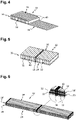
figure 8 est une coupe schématique de deux matelas d'isolation thermique illustrant un mode de réalisation de l'invention, - La
figure 9 est une coupe schématique d'une paroi d'un réservoir incorporant les matelas d'isolation thermique visibles sur lafigure 8 , - La
figure 10 représente des vues de dessus de matelas d'isolation thermique illustrant différents modes de réalisation de l'invention, - La
figure 11 est une coupe schématique de deux matelas d'isolation thermique illustrant un mode de réalisation de l'invention, et - La
figure 12 est une coupe schématique de deux matelas d'isolation thermique illustrant un mode de réalisation de l'invention. - Sur les
figures 2 et 3 , un réservoir 20 comprend une paroi 22 séparant une zone intérieure Zi et une zone extérieure Ze. - Selon une application, ce réservoir 20 est configuré pour stocker un produit à une température cryogénique, comme de l'hydrogène liquide à une température de l'ordre de -250°C par exemple. Un aéronef fonctionnant à l'hydrogène peut comprendre au moins un tel réservoir 20.
- Selon une configuration, le réservoir 20 présente une forme sphérique.
- Bien entendu, l'invention n'est ni limitée à cette application ni à cette forme pour le réservoir 20.
- Selon un mode de réalisation, la paroi 22 comprend une barrière intérieure 24 étanche présentant une première face F24 orientée vers la zone intérieure Zi et une deuxième face F24' opposée à la première face F24, une barrière extérieure 26 étanche, entourant la première barrière intérieure 24, présentant une première face F26 orientée vers la zone extérieure Ze et une deuxième face F26' opposée à la première face F26, un volume intercalaire 28 entre les barrières intérieure et extérieure 24, 26 étanches ainsi qu'au moins une couche isolante 30 positionnée dans le volume intercalaire 28, entre les barrières intérieure et extérieure 24, 26.
- Comme illustré sur la
figure 2 par exemple, chaque couche isolante 30 comprend au moins un matelas d'isolation thermique 32 comportant une enveloppe 34 contenant des premières microsphères 36 et présentant un niveau de vide poussé. - Par niveau de vide poussé, on entend que l'atmosphère contenue dans l'enveloppe 34 présente une pression inférieure à 10-2 bar, de préférence inférieure à 10-3 bar.
- Par microsphère, on entend un élément présentant une forme approximativement sphérique et creuse, de paroi fine et d'un diamètre inférieur à 1 mm en moyenne, de préférence supérieur à 1 µm en moyenne.
- Selon une configuration, chaque couche isolante 30 comprend plusieurs matelas d'isolation thermique 32 juxtaposés.
- Selon un mode de réalisation visible sur les
figures 4 et 5 , la paroi 22 comprend une seule couche isolante 30 comportant plusieurs matelas d'isolation thermique 32 juxtaposés. - Selon d'autres modes de réalisation visibles sur les
figures 2, 3 ,6 , la paroi 22 comprend plusieurs couches isolantes 30, 30' superposées les unes sur les autres comportant plusieurs matelas d'isolation thermique 32 juxtaposés et superposés. - Selon un mode de réalisation, l'enveloppe 34 comprend au moins un film en matériau synthétique comme un film en polyéthylène (PE), en polyéthylène téréphtalate (PET) ou en polyamide (PA) par exemple. L'enveloppe 34 peut comprendre un revêtement ou un film en surface métallique, comme en alliage d'aluminium par exemple.
- Selon un mode de réalisation, les premières microsphères 36 ont un diamètre compris entre 0,1 et 500 µm. Ces premières microsphères 36 sont réalisées en un matériau présentant une faible conductivité thermique. A titre d'exemple, les premières microsphères 36 sont des microsphères commercialisées sous la dénomination commerciale « Glass Bubbles ».
- Après le remplissage de chaque enveloppe 34 avec les premières microsphères 36, l'air présent dans l'enveloppe 34 est retiré de manière à obtenir un niveau de vide poussé à l'intérieur de l'enveloppe 34.
- Bien entendu, l'invention n'est pas limitée à ce mode de réalisation pour les matelas d'isolation thermique 32. Ainsi, les premières microsphères 36 pourraient être remplacées par toute autre matière présentant une faible conductivité thermique. Ainsi, les matelas d'isolation thermique 32 peuvent être de type VIP (pour Vacuum Insulated Panel en anglais) ou de type MIP (pour Microsphere Insulated Panel en anglais). Quel que soit le mode de réalisation, chaque matelas d'isolation thermique 32 comprend une enveloppe 34 contenant au moins une matière et présentant un niveau de vide poussé.
- Chaque matelas d'isolation thermique 32 comprend une première face 32.1 orientée vers la barrière intérieure 24, une deuxième face 32.2 opposée à la première face 32.1 et orientée vers la barrière extérieure 26 ainsi qu'au moins un chant 32.3 reliant les première et deuxième faces 32.1, 32.2. Selon une configuration, les première et deuxième faces 32.1, 32.2 présentent un contour identique qui peut être carré ou rectangulaire comme illustré sur la partie (A) de la
figure 10 , triangulaire comme illustré sur la partie (B) de lafigure 10 , hexagonal comme illustré sur la partie (C) de lafigure 10 . Bien entendu, l'invention n'est pas limitée à ces formes pour le contour des première et deuxième faces 32.1, 32.2 des matelas d'isolation thermique 32. Selon un agencement, les matelas d'isolation thermique 32 d'une même couche isolante 30, 30' ont tous le même contour, ce dernier étant choisi notamment en fonction de la géométrie de la couche isolante 30, 30' afin d'optimiser son recouvrement. Selon un mode de réalisation, les chants 32.3 des matelas d'isolation thermique 32 sont plats et sensiblement perpendiculaires aux première et deuxième faces 32.1, 32.2. Bien entendu, l'invention n'est pas limitée à cette géométrie. - Selon un mode de réalisation visible sur la
figure 11 , un premier matelas d'isolation thermique 32 comprend, au niveau d'un premier chant 32.3, un décrochement 52 positionné au niveau d'une zone de jonction reliant le premier chant 32.3 et la première face 32.1, et au niveau d'un deuxième chant 32.3', opposé au premier chant 32.3, une extension 53 dans le prolongement de la première face 32.1, configurée pour se loger dans le décrochement 52' d'un deuxième matelas d'isolation thermique 32'. - Selon un mode de réalisation visible sur la
figure 12 , les chants 32.3 peuvent être inclinés. Les modes de réalisation visibles sur lesfigures 11 et 12 permettent d'obtenir un meilleur recouvrement selon une direction radiale (sensiblement perpendiculaire aux barrières intérieure et extérieure 24, 26). D'autres formes et géométries sont envisageables pour les chants 32.3. - Selon un mode de réalisation illustré sur les
figures 2 et 3 , le volume intercalaire 28 entre les barrières intérieure et extérieure 24, 26 comprend deux couches isolantes 30, 30' de matelas d'isolation thermique 32 juxtaposés. Bien entendu, l'invention n'est pas limitée à ce nombre de couches. Ainsi, il est possible de prévoir un nombre plus élevé de couches de matelas d'isolation thermique 32 juxtaposés, en fonction des performances souhaitées d'isolation thermique. - Pour chaque couche isolante 30, 30', les matelas d'isolation thermique 32 sont juxtaposés de sorte que leurs chants soient positionnés les uns contre les autres ou faiblement espacés et qu'il ne subsiste que de faibles interstices 38 entre les matelas d'isolation thermique 32.
- Selon une particularité de l'invention, le volume intercalaire 28 entre les barrières intérieure et extérieure 24, 26 est rempli de deuxièmes microsphères 40 en dehors des matelas d'isolation thermique 32. En complément, le volume intercalaire 28 présente un niveau de vide poussé.
- Selon une configuration, les deuxièmes microsphères 40 sont réparties autour des matelas d'isolation thermique 32 de manière à les envelopper.
- Selon un mode de réalisation, les deuxièmes microsphères 40 contenues dans le volume intercalaire 28 à l'extérieur des enveloppes 34 des matelas d'isolation thermique 32 sont identiques à celles contenues dans les enveloppes 34.
- Les matelas d'isolation thermique 32 occupent au moins 25% du volume intercalaire 28, les deuxièmes microsphères 40 complétant le reste du volume intercalaire 28.
- Selon un mode de réalisation, une majorité du volume intercalaire 28 est occupée par les matelas d'isolation thermique 32, les deuxièmes microsphères 40 complétant le restant du volume intercalaire 28. Par majorité du volume intercalaire 28, on entend qu'au moins 70% du volume intercalaire 28 sont occupés par les matelas d'isolation thermique 32, les deuxièmes microsphères 40 occupant le reste du volume intercalaire 28.
- Ainsi, les matelas d'isolation thermique 32 assurent l'essentiel des propriétés isolantes de la paroi 22.
- Selon l'invention, en cas de fuite de la barrière extérieure 26, la perte de vide au niveau du volume intercalaire 28 n'affecte quasiment pas les propriétés isolantes de la paroi 22 dans la mesure où les matelas d'isolation thermique 32 ne sont pas impactés et assurent pleinement la fonction d'isolant thermique. Même en cas de perte de vide, les deuxièmes microsphères 40 présentes dans le volume intercalaire 28 à l'extérieur des matelas d'isolation thermique 32 ont des propriétés isolantes à pression ambiante supérieures à celles d'un isolant multicouche de l'art antérieur.
- De plus, même si l'enveloppe 34 d'un matelas d'isolation thermique 32 n'est plus étanche, les propriétés isolantes de ce matelas d'isolation thermique 32 ne sont pas affectées car il est positionné dans le volume intercalaire 28 soumis au vide.
- D'une couche à l'autre, les matelas d'isolation thermique 32 sont agencés de sorte que les interstices 38 d'une première couche isolante 30 soient décalés par rapport aux interstices 38 d'une deuxième couche isolante 30'. Le fait de prévoir plusieurs couches isolantes 30 permet de réduire l'épaisseur des matelas d'isolation thermique 32 de chaque couche. Le fait de décaler les matelas d'isolation thermique 32 d'une couche à l'autre permet d'obtenir une isolation efficace même en cas de perte du vide dans le volume intercalaire 28.
- Les épaisseurs des matelas d'isolation thermique 32 ainsi que le nombre de couches sont déterminés en fonction des caractéristiques thermiques recherchées pour la paroi 22.
- Au moins une première barrière parmi les barrières intérieure et extérieure 24, 26 est rigide et configurée pour ne pas se déformer lorsqu'un gradient de pression important (supérieur à 10 bars) apparaît entre ses première et deuxième faces F24/F24', F26/F26'.
- Selon une configuration visible sur la
figure 2 , la barrière intérieure 24 est rigide et la barrière extérieure 26 est en matériau souple. - Selon une deuxième configuration visible sur la
figure 3 , la barrière extérieure 26 est rigide et la barrière intérieure 24 est en matériau souple. Selon cette configuration, tous les matelas d'isolation thermique 32 sont en compression. Les microsphères et la pression interne permettent de maintenir la barrière intérieure 24 souple en place. - Selon une autre configuration, les barrières intérieure et extérieure 24, 26 sont rigides.
- Les barrières intérieure et/ou extérieure 24, 26 peuvent être métalliques, en matériau composite ou en tout autre matériau.
- De nombreux modes de réalisation sont envisageables pour réaliser les barrières intérieure et extérieure 24, 26. A titre d'exemple, la barrière intérieure ou extérieure 24, 26 peut être réalisée en INVAR, en polyéthylène (PE), en polyéthylène téréphtalate (PET), en polyamide (PA) ou autres.
- La barrière intérieure 24 est réalisée en un matériau compatible avec l'hydrogène lorsque le réservoir 20 est configuré pour stocker de l'hydrogène.
- Le fait qu'au moins une barrière parmi les barrières intérieure et extérieure 24, 26 soit en matériau souple facilite le tirage au vide dans le volume intercalaire 28. Malgré leur compression due à la mise au vide, les deuxièmes microsphères 40 ne perdent pas significativement leurs propriétés isolantes contrairement aux isolants multicouches de l'art antérieur.
- Le réservoir 20 comprend au moins un système de liaison 42 rigide relié à la barrière intérieure ou extérieure 24, 26 rigide. Le fait de prévoir une barrière extérieure 26 rigide à laquelle est relié chaque système de liaison 42 permet d'éviter que ce dernier ne traverse la paroi 22 et que la chaleur ne pénètre en direction du produit stocké dans le réservoir 20.
- Selon un mode opératoire illustré sur la
figure 7 , le procédé de fabrication du réservoir comprend une étape de positionnement des matelas d'isolation thermique 32 sur la barrière intérieure 24 rigide, comme illustré sur la partie (A) de lafigure 7 , les matelas d'isolation thermique 32 étant liés à la barrière intérieure 24 et éventuellement entre eux par des éléments de liaison 44, comme des bandes auto-agrippantes par exemple. Les matelas d'isolation thermique 32 sont juxtaposés et superposés de manière à former les différentes couches isolantes 30, comme illustré sur la partie (B) de lafigure 7 . Le procédé comprend ensuite une étape de mise en place de la barrière extérieure 26 sur la dernière couche isolante 30', comme illustré sur la partie (C), une étape de déshumidification du volume intercalaire 28, comme illustré sur la partie (D), en chauffant ou en injectant un gaz inerte, une étape de remplissage du volume intercalaire 28 avec des deuxièmes microsphères 40, comme illustré sur la partie (E), et enfin une étape de tirage au vide du volume intercalaire 28, avec une pompe 46 par exemple, de manière à obtenir le niveau de vide souhaité. - Si la barrière intérieure 24 est souple et la barrière extérieure 26 est rigide, le procédé comprend une étape de positionnement des matelas d'isolation thermique 32 contre la barrière extérieure 26, en les reliant à cette dernière, de manière à former au moins une couche isolante 30, une étape de mise en place de la barrière intérieure 24 de manière à délimiter un volume intercalaire dans lequel sont positionnés les matelas d'isolation thermique 32, une étape de déshumidification du volume intercalaire 28, une étape de remplissage du volume intercalaire avec des microsphères 40 puis une étape de tirage au vide du volume intercalaire 28.
- Quel que soit le mode de réalisation, les matelas d'isolation thermique 32 sont positionnés contre la barrière intérieure ou extérieure 24, 26 rigide, puis l'autre barrière intérieure ou extérieure 24, 26 est mise en place de manière à délimiter un volume intercalaire 28 dans lequel sont positionnés les matelas d'isolation thermique 32.
- En raison du volume réduit restant à remplir avec les deuxièmes microsphères 40, l'étape de remplissage est simplifiée et nécessite un faible volume de deuxièmes microsphères 40. Du fait de ce volume réduit, les étapes de déshumidification et de tirage au vide sont également simplifiées.
- Selon un mode de réalisation visible sur la
figure 9 , la paroi 22 du réservoir comprend une barrière intermédiaire 48 étanche, positionnée entre les barrières intérieure et extérieure 24, 26, espacée de ces dernières, divisant le volume intercalaire 28 entre les barrières intérieure et extérieure 24, 26 en une première zone Z1 située entre la barrière intermédiaire 48 et la barrière intérieure 24 et une deuxième zone Z2 située entre la barrière intermédiaire 48 et la barrière extérieure 26. Selon une configuration, la barrière intermédiaire 48 comprend les matelas d'isolation thermique 32 d'une même couche 30 reliés entre eux de manière étanche pour former la barrière intermédiaire 48 étanche. - Selon un mode opératoire, pour les relier, les matelas d'isolation thermique 32 sont thermosoudés. Bien entendu, l'invention n'est pas limitée à cette technique pour relier les matelas d'isolation thermique 32 entre eux.
- Selon une configuration illustrée sur la
figure 8 , au moins un premier matelas d'isolation thermique 32 comprend au moins une extension 50, sous la forme d'un volet par exemple, comportant une zone de chevauchement 50.1 recouvrant un deuxième matelas d'isolation thermique 32', ladite zone de chevauchement 50.1 étant reliée de manière étanche avec ce dernier. - Selon un agencement, l'extension 50 est située dans le prolongement de la deuxième face 32.2 du matelas d'isolation thermique 32. Bien entendu, l'invention n'est pas limitée à cet agencement pour l'extension 50 qui pourrait être positionnée dans le prolongement de la première face 32.1 du matelas d'isolation thermique 32.
- Bien entendu, l'invention n'est pas limitée à ce mode de réalisation pour la barrière intermédiaire 48. Ainsi, cette dernière pourrait être distincte des matelas d'isolation thermique 32. Grâce à la barrière intermédiaire 48, en cas de fuite au niveau de la barrière intérieure ou extérieure 24, 26, seule la première ou deuxième zone Z1, Z2 adjacente à cette barrière intérieure ou extérieure 24, 26 est re-pressurisée. L'autre zone conserve un niveau de vide poussé.
- Selon un mode de réalisation, la paroi 22 comprend au moins un conduit 54, fixe ou amovible, débouchant dans la première zone Z1, traversant la deuxième zone Z2 et la barrière extérieure 26 pourfaire communiquer la première zone Z1 avec la zone extérieure Ze. Ce conduit 54 peut être utilisé pour la mise sous vide de la première zone Z1 et son remplissage de microsphères 40.
- En variante ou en complément, la barrière intermédiaire 48 comprend au moins un orifice 56 configuré pour faire communiquer les première et deuxième zones Z1, Z2. Cet orifice 56 peut être utilisé pour la mise sous vide de la première zone Z1 et son remplissage de microsphères 40. Selon une configuration, chaque orifice 56 est équipé d'un clapet anti-retour 58 configuré pour permettre une extraction des gaz présents dans la première zone Z1, tout en interdisant tout flux de gaz de la deuxième zone Z2 vers la première zone Z1, notamment en cas de repressurisation accidentelle de la deuxième zone Z2.
Claims (15)
- Réservoir comprenant une paroi (22) séparant une zone intérieure (Zi) et une zone extérieure (Ze), la paroi (22) comportant une barrière intérieure (24) étanche, une barrière extérieure (26) étanche, un volume intercalaire (28) entre les barrières intérieure et extérieure (24, 26) ainsi qu'au moins une couche isolante (30) positionnée dans le volume intercalaire (28) et comportant au moins un matelas d'isolation thermique (32), ledit matelas d'isolation thermique (32) comprenant une enveloppe (34) contenant au moins une matière et présentant un niveau de vide poussé, caractérisé en ce que le volume intercalaire (28) contient des microsphères (40) en dehors des matelas d'isolation thermique (32) et présente un niveau de vide poussé.
- Réservoir selon la revendication précédente, caractérisé en ce que les microsphères (40) sont réparties autour des matelas d'isolation thermique (32) de manière à les envelopper.
- Réservoir selon l'une des revendications précédentes, caractérisé en ce que la paroi (22) comprend au moins des première et deuxième couches isolantes (30, 30') présentant chacune plusieurs matelas d'isolation thermique (32) juxtaposés et séparés par des interstices (38), les interstices (38) de la première couche isolante (30) étant décalés par rapport aux interstices (38) de la deuxième couche isolante (30').
- Réservoir selon l'une des revendications précédentes, caractérisé en ce qu'au moins une barrière parmi les barrières intérieure et extérieure (24, 26) est rigide.
- Réservoir selon la revendication précédente, caractérisé en ce que la barrière intérieure (24) est rigide et la barrière extérieure (26) est en matériau souple.
- Réservoir selon la revendication 4, caractérisé en ce que la barrière extérieure (26) est rigide et la barrière intérieure (24) est en matériau souple.
- Réservoir selon la revendication précédente, caractérisé en ce que le réservoir (20) comprend au moins un système de liaison (42) rigide relié à la barrière extérieure (26) rigide.
- Réservoir selon l'une des revendications précédentes, caractérisé en ce que l'enveloppe (34) de chaque matelas d'isolation thermique (32) contient des microsphères (36).
- Réservoir selon l'une des revendications précédentes, caractérisé en ce que la paroi (22) comprend une barrière intermédiaire (48) étanche, positionnée entre les barrières intérieure et extérieure (24, 26), divisant le volume intercalaire (28) en une première zone (Z1) située entre la barrière intermédiaire (48) et la barrière intérieure (24) et une deuxième zone (Z2) située entre la barrière intermédiaire (48) et la barrière extérieure (26).
- Réservoir selon la revendication précédente, caractérisé en ce que la barrière intermédiaire (48) comprend les matelas d'isolation thermique (32) d'une même couche isolante (30) reliés entre eux de manière étanche.
- Réservoir selon la revendication précédente, caractérisé en ce qu'au moins un premier matelas d'isolation thermique (32) comprend au moins une extension (50) présentant une zone de chevauchement (50.1), recouvrant un deuxième matelas d'isolation thermique (32'), reliée à ce dernier de manière étanche.
- Réservoir selon l'une des revendications 9 à 11, caractérisé en ce que la paroi (22) comprend au moins un conduit (54) débouchant dans la première zone (Z1), ledit conduit (54) traversant la deuxième zone (Z2) et la barrière extérieure (26).
- Réservoir selon l'une des revendications 9 à 12, caractérisé en ce que la barrière intermédiaire (48) comprend au moins un orifice (56) configuré pour faire communiquer les première et deuxième zones (Z1, Z2), ledit orifice (56) étant équipé d'un clapet anti-retour (58) configuré pour permettre une extraction des gaz présents dans la première zone (Z1), tout en interdisant tout flux de gaz de la deuxième zone (Z2) vers la première zone (Z1).
- Procédé de fabrication d'un réservoir selon l'une quelconque des revendications précédentes, caractérisé en ce que le procédé comprend une étape de positionnement de matelas d'isolation thermique (32) contre une barrière intérieure ou extérieure (24, 26) rigide pour former au moins une couche isolante (30), une étape de mise en place d'une autre barrière intérieure ou extérieure (24, 26) pour délimiter un volume intercalaire (28) dans lequel sont positionnés les matelas d'isolation thermique (32), une étape de remplissage du volume intercalaire (28) avec des microsphères (40) et une étape de tirage au vide du volume intercalaire (28).
- Procédé de fabrication selon la revendication précédente, caractérisé en ce que lors de l'étape de positionnement, les matelas d'isolation thermique (32) sont reliés à la barrière intérieure ou extérieure (24, 26) rigide.
Applications Claiming Priority (1)
| Application Number | Priority Date | Filing Date | Title |
|---|---|---|---|
| FR2105876A FR3123706A1 (fr) | 2021-06-04 | 2021-06-04 | Réservoir présentant une isolation renforcée combinant des matelas d’isolation thermique ainsi que des microsphères et procédé de fabrication d’un tel réservoir |
Publications (2)
| Publication Number | Publication Date |
|---|---|
| EP4098932A1 true EP4098932A1 (fr) | 2022-12-07 |
| EP4098932B1 EP4098932B1 (fr) | 2023-12-20 |
Family
ID=77519225
Family Applications (1)
| Application Number | Title | Priority Date | Filing Date |
|---|---|---|---|
| EP22172884.3A Active EP4098932B1 (fr) | 2021-06-04 | 2022-05-12 | Réservoir présentant une isolation renforcée combinant des matelas d'isolation thermique ainsi que des microsphères et procédé de fabrication d'un tel réservoir |
Country Status (4)
| Country | Link |
|---|---|
| US (1) | US11867358B2 (fr) |
| EP (1) | EP4098932B1 (fr) |
| CN (1) | CN115435236A (fr) |
| FR (1) | FR3123706A1 (fr) |
Families Citing this family (2)
| Publication number | Priority date | Publication date | Assignee | Title |
|---|---|---|---|---|
| WO2024172838A2 (fr) * | 2023-01-07 | 2024-08-22 | Zeroavia Ltd | Système d'isolation thermo-structurelle cryogénique |
| WO2025217376A1 (fr) * | 2024-04-10 | 2025-10-16 | Joby Aero, Inc. | Structure d'isolation porteuse de charge en mosaïque pour récipients thermiques |
Citations (5)
| Publication number | Priority date | Publication date | Assignee | Title |
|---|---|---|---|---|
| EP0012038A1 (fr) * | 1978-12-04 | 1980-06-11 | Air Products And Chemicals, Inc. | Système utilisant une superisolation |
| US20030203149A1 (en) * | 2002-02-26 | 2003-10-30 | Allen Mark S. | Microsphere insulation systems |
| US20050005571A1 (en) * | 2002-02-11 | 2005-01-13 | Saes Getters S.P.A. | Process for introducing an insulating system in an interspace |
| US20120279971A1 (en) * | 2008-09-23 | 2012-11-08 | Aerovironment Inc. | Cryogenic Liquid Tank |
| EP3348893A1 (fr) * | 2017-01-13 | 2018-07-18 | Nantong Cimc Tank Equipment Co., Ltd. | Conteneur citerne |
Family Cites Families (8)
| Publication number | Priority date | Publication date | Assignee | Title |
|---|---|---|---|---|
| US3257265A (en) * | 1962-09-14 | 1966-06-21 | Aerojet General Co | Laminated cryogenic insulation |
| DE1266078B (de) * | 1965-05-18 | 1968-04-11 | Linde Ag | Waermeisoliermaterial und Verfahren zu seiner Herstellung |
| US3390703A (en) * | 1966-09-30 | 1968-07-02 | Ryan Ind Inc | Multilayer insulating means |
| US3607169A (en) * | 1968-11-07 | 1971-09-21 | Exxon Research Engineering Co | Method for producing evacuated glass microspheres |
| US4027379A (en) * | 1973-06-15 | 1977-06-07 | The Dow Chemical Company | Method of insulating cryogenic vessels |
| CH587979A5 (fr) * | 1976-02-06 | 1977-05-31 | Sulzer Ag | |
| DE2750457A1 (de) * | 1976-12-21 | 1978-06-22 | Gen Electric | Thermische isolationsstruktur |
| DE10352568B4 (de) * | 2003-11-11 | 2017-05-24 | Bayerische Motoren Werke Aktiengesellschaft | Druckbehälter mit geringem Wärmeeintrag für kondensierte Gase |
-
2021
- 2021-06-04 FR FR2105876A patent/FR3123706A1/fr not_active Ceased
-
2022
- 2022-05-12 EP EP22172884.3A patent/EP4098932B1/fr active Active
- 2022-06-01 US US17/830,175 patent/US11867358B2/en active Active
- 2022-06-01 CN CN202210619041.3A patent/CN115435236A/zh active Pending
Patent Citations (6)
| Publication number | Priority date | Publication date | Assignee | Title |
|---|---|---|---|---|
| EP0012038A1 (fr) * | 1978-12-04 | 1980-06-11 | Air Products And Chemicals, Inc. | Système utilisant une superisolation |
| US20050005571A1 (en) * | 2002-02-11 | 2005-01-13 | Saes Getters S.P.A. | Process for introducing an insulating system in an interspace |
| US20030203149A1 (en) * | 2002-02-26 | 2003-10-30 | Allen Mark S. | Microsphere insulation systems |
| US6858280B2 (en) | 2002-02-26 | 2005-02-22 | Technology Applications, Inc. | Microsphere insulation systems |
| US20120279971A1 (en) * | 2008-09-23 | 2012-11-08 | Aerovironment Inc. | Cryogenic Liquid Tank |
| EP3348893A1 (fr) * | 2017-01-13 | 2018-07-18 | Nantong Cimc Tank Equipment Co., Ltd. | Conteneur citerne |
Also Published As
| Publication number | Publication date |
|---|---|
| US11867358B2 (en) | 2024-01-09 |
| FR3123706A1 (fr) | 2022-12-09 |
| EP4098932B1 (fr) | 2023-12-20 |
| CN115435236A (zh) | 2022-12-06 |
| US20220390071A1 (en) | 2022-12-08 |
Similar Documents
| Publication | Publication Date | Title |
|---|---|---|
| EP4098932B1 (fr) | Réservoir présentant une isolation renforcée combinant des matelas d'isolation thermique ainsi que des microsphères et procédé de fabrication d'un tel réservoir | |
| EP2453159B1 (fr) | Cuve a membrane ondulée renforcée | |
| WO2012084874A1 (fr) | Dispositif d'isolation thermique mince à haute performance | |
| EP1034395A1 (fr) | Conteneur, notamment pour reservoir de gaz liquefie sous pression, et son procede de fabrication | |
| EP2740662B1 (fr) | Verrière perfectionnée pour aéronef | |
| EP4182601A1 (fr) | Dispositif de stockage de fluide cryogénique et véhicule comprenant un tel dispositif | |
| FR2781555A1 (fr) | Concept et procede de fabrication de reservoir de fluide, d'air comprime ou autre gaz a haute pression | |
| EP1160501A1 (fr) | Procédé de fabrication d'un réservoir pour fluide cryogénique et réservoir ainsi obtenu | |
| FR2744174A1 (fr) | Agencement de paroi pour des parois de propulseurs refroidies par circulation de propergols | |
| WO2021165607A1 (fr) | Réservoir pour ergols cryogéniques | |
| CA2803974A1 (fr) | Procede de realisation d'un caisson central de voilure | |
| EP1644659B1 (fr) | Reservoir de fluide cryogenique et utilisation dans un vehicule automobile | |
| WO2016102811A1 (fr) | Panneau d'isolation sous vide avec joint d'étanchéité amélioré | |
| BE1013181A5 (fr) | Jonction composite pour le montage d'au moins un organe exterieur sur un panneau sandwich, et panneau integrant au moins une telle jonction. | |
| FR2505730A1 (fr) | Materiau composite d'amortissement de chocs et de vibrations | |
| EP3870890A1 (fr) | Cuve etanche et thermiquement isolante | |
| WO2023187120A1 (fr) | Réservoir cryogénique de forme complexe et à indice gravimétrique élevé et procédé de fabrication correspondant | |
| WO2024002903A1 (fr) | Attache formant un renfort pour réservoir et procédés de fabrication et de mise en forme correspondants | |
| EP4380861A1 (fr) | Procede de fabrication d'un porte-diaphragme pour amortisseur oleopneumatique | |
| WO2023084001A1 (fr) | Armature pour structure en matériau composite, et structure en matériau composite comprenant une telle armature | |
| FR3136830A1 (fr) | Réservoir modulaire de gaz sous pression | |
| FR3129444A1 (fr) | Ressort composite de suspension en soufflet | |
| FR3159152A1 (fr) | Réservoir d’ergol cryogénique pour un moteur d’engin spatial | |
| FR2981425A1 (fr) | Dispositif de protection incendie. | |
| FR3102808A1 (fr) | Dispositif de protection thermique amélioré pour tuyère |
Legal Events
| Date | Code | Title | Description |
|---|---|---|---|
| PUAI | Public reference made under article 153(3) epc to a published international application that has entered the european phase |
Free format text: ORIGINAL CODE: 0009012 |
|
| STAA | Information on the status of an ep patent application or granted ep patent |
Free format text: STATUS: THE APPLICATION HAS BEEN PUBLISHED |
|
| AK | Designated contracting states |
Kind code of ref document: A1 Designated state(s): AL AT BE BG CH CY CZ DE DK EE ES FI FR GB GR HR HU IE IS IT LI LT LU LV MC MK MT NL NO PL PT RO RS SE SI SK SM TR |
|
| STAA | Information on the status of an ep patent application or granted ep patent |
Free format text: STATUS: REQUEST FOR EXAMINATION WAS MADE |
|
| 17P | Request for examination filed |
Effective date: 20230525 |
|
| RBV | Designated contracting states (corrected) |
Designated state(s): AL AT BE BG CH CY CZ DE DK EE ES FI FR GB GR HR HU IE IS IT LI LT LU LV MC MK MT NL NO PL PT RO RS SE SI SK SM TR |
|
| GRAP | Despatch of communication of intention to grant a patent |
Free format text: ORIGINAL CODE: EPIDOSNIGR1 |
|
| STAA | Information on the status of an ep patent application or granted ep patent |
Free format text: STATUS: GRANT OF PATENT IS INTENDED |
|
| RIC1 | Information provided on ipc code assigned before grant |
Ipc: F17C 13/00 20060101AFI20230706BHEP |
|
| INTG | Intention to grant announced |
Effective date: 20230724 |
|
| GRAS | Grant fee paid |
Free format text: ORIGINAL CODE: EPIDOSNIGR3 |
|
| GRAA | (expected) grant |
Free format text: ORIGINAL CODE: 0009210 |
|
| STAA | Information on the status of an ep patent application or granted ep patent |
Free format text: STATUS: THE PATENT HAS BEEN GRANTED |
|
| AK | Designated contracting states |
Kind code of ref document: B1 Designated state(s): AL AT BE BG CH CY CZ DE DK EE ES FI FR GB GR HR HU IE IS IT LI LT LU LV MC MK MT NL NO PL PT RO RS SE SI SK SM TR |
|
| REG | Reference to a national code |
Ref country code: GB Ref legal event code: FG4D Free format text: NOT ENGLISH |
|
| REG | Reference to a national code |
Ref country code: CH Ref legal event code: EP |
|
| REG | Reference to a national code |
Ref country code: DE Ref legal event code: R096 Ref document number: 602022001361 Country of ref document: DE |
|
| REG | Reference to a national code |
Ref country code: IE Ref legal event code: FG4D Free format text: LANGUAGE OF EP DOCUMENT: FRENCH |
|
| PG25 | Lapsed in a contracting state [announced via postgrant information from national office to epo] |
Ref country code: GR Free format text: LAPSE BECAUSE OF FAILURE TO SUBMIT A TRANSLATION OF THE DESCRIPTION OR TO PAY THE FEE WITHIN THE PRESCRIBED TIME-LIMIT Effective date: 20240321 |
|
| REG | Reference to a national code |
Ref country code: LT Ref legal event code: MG9D |
|
| PG25 | Lapsed in a contracting state [announced via postgrant information from national office to epo] |
Ref country code: LT Free format text: LAPSE BECAUSE OF FAILURE TO SUBMIT A TRANSLATION OF THE DESCRIPTION OR TO PAY THE FEE WITHIN THE PRESCRIBED TIME-LIMIT Effective date: 20231220 |
|
| REG | Reference to a national code |
Ref country code: NL Ref legal event code: MP Effective date: 20231220 |
|
| PG25 | Lapsed in a contracting state [announced via postgrant information from national office to epo] |
Ref country code: ES Free format text: LAPSE BECAUSE OF FAILURE TO SUBMIT A TRANSLATION OF THE DESCRIPTION OR TO PAY THE FEE WITHIN THE PRESCRIBED TIME-LIMIT Effective date: 20231220 |
|
| PG25 | Lapsed in a contracting state [announced via postgrant information from national office to epo] |
Ref country code: LT Free format text: LAPSE BECAUSE OF FAILURE TO SUBMIT A TRANSLATION OF THE DESCRIPTION OR TO PAY THE FEE WITHIN THE PRESCRIBED TIME-LIMIT Effective date: 20231220 Ref country code: GR Free format text: LAPSE BECAUSE OF FAILURE TO SUBMIT A TRANSLATION OF THE DESCRIPTION OR TO PAY THE FEE WITHIN THE PRESCRIBED TIME-LIMIT Effective date: 20240321 Ref country code: FI Free format text: LAPSE BECAUSE OF FAILURE TO SUBMIT A TRANSLATION OF THE DESCRIPTION OR TO PAY THE FEE WITHIN THE PRESCRIBED TIME-LIMIT Effective date: 20231220 Ref country code: ES Free format text: LAPSE BECAUSE OF FAILURE TO SUBMIT A TRANSLATION OF THE DESCRIPTION OR TO PAY THE FEE WITHIN THE PRESCRIBED TIME-LIMIT Effective date: 20231220 Ref country code: BG Free format text: LAPSE BECAUSE OF FAILURE TO SUBMIT A TRANSLATION OF THE DESCRIPTION OR TO PAY THE FEE WITHIN THE PRESCRIBED TIME-LIMIT Effective date: 20240320 |
|
| REG | Reference to a national code |
Ref country code: AT Ref legal event code: MK05 Ref document number: 1642739 Country of ref document: AT Kind code of ref document: T Effective date: 20231220 |
|
| PG25 | Lapsed in a contracting state [announced via postgrant information from national office to epo] |
Ref country code: NL Free format text: LAPSE BECAUSE OF FAILURE TO SUBMIT A TRANSLATION OF THE DESCRIPTION OR TO PAY THE FEE WITHIN THE PRESCRIBED TIME-LIMIT Effective date: 20231220 |
|
| PG25 | Lapsed in a contracting state [announced via postgrant information from national office to epo] |
Ref country code: SE Free format text: LAPSE BECAUSE OF FAILURE TO SUBMIT A TRANSLATION OF THE DESCRIPTION OR TO PAY THE FEE WITHIN THE PRESCRIBED TIME-LIMIT Effective date: 20231220 Ref country code: RS Free format text: LAPSE BECAUSE OF FAILURE TO SUBMIT A TRANSLATION OF THE DESCRIPTION OR TO PAY THE FEE WITHIN THE PRESCRIBED TIME-LIMIT Effective date: 20231220 Ref country code: NO Free format text: LAPSE BECAUSE OF FAILURE TO SUBMIT A TRANSLATION OF THE DESCRIPTION OR TO PAY THE FEE WITHIN THE PRESCRIBED TIME-LIMIT Effective date: 20240320 Ref country code: NL Free format text: LAPSE BECAUSE OF FAILURE TO SUBMIT A TRANSLATION OF THE DESCRIPTION OR TO PAY THE FEE WITHIN THE PRESCRIBED TIME-LIMIT Effective date: 20231220 Ref country code: LV Free format text: LAPSE BECAUSE OF FAILURE TO SUBMIT A TRANSLATION OF THE DESCRIPTION OR TO PAY THE FEE WITHIN THE PRESCRIBED TIME-LIMIT Effective date: 20231220 Ref country code: HR Free format text: LAPSE BECAUSE OF FAILURE TO SUBMIT A TRANSLATION OF THE DESCRIPTION OR TO PAY THE FEE WITHIN THE PRESCRIBED TIME-LIMIT Effective date: 20231220 |
|
| PG25 | Lapsed in a contracting state [announced via postgrant information from national office to epo] |
Ref country code: IS Free format text: LAPSE BECAUSE OF FAILURE TO SUBMIT A TRANSLATION OF THE DESCRIPTION OR TO PAY THE FEE WITHIN THE PRESCRIBED TIME-LIMIT Effective date: 20240420 |
|
| PG25 | Lapsed in a contracting state [announced via postgrant information from national office to epo] |
Ref country code: CZ Free format text: LAPSE BECAUSE OF FAILURE TO SUBMIT A TRANSLATION OF THE DESCRIPTION OR TO PAY THE FEE WITHIN THE PRESCRIBED TIME-LIMIT Effective date: 20231220 Ref country code: AT Free format text: LAPSE BECAUSE OF FAILURE TO SUBMIT A TRANSLATION OF THE DESCRIPTION OR TO PAY THE FEE WITHIN THE PRESCRIBED TIME-LIMIT Effective date: 20231220 |
|
| PG25 | Lapsed in a contracting state [announced via postgrant information from national office to epo] |
Ref country code: SK Free format text: LAPSE BECAUSE OF FAILURE TO SUBMIT A TRANSLATION OF THE DESCRIPTION OR TO PAY THE FEE WITHIN THE PRESCRIBED TIME-LIMIT Effective date: 20231220 |
|
| PG25 | Lapsed in a contracting state [announced via postgrant information from national office to epo] |
Ref country code: SM Free format text: LAPSE BECAUSE OF FAILURE TO SUBMIT A TRANSLATION OF THE DESCRIPTION OR TO PAY THE FEE WITHIN THE PRESCRIBED TIME-LIMIT Effective date: 20231220 Ref country code: SK Free format text: LAPSE BECAUSE OF FAILURE TO SUBMIT A TRANSLATION OF THE DESCRIPTION OR TO PAY THE FEE WITHIN THE PRESCRIBED TIME-LIMIT Effective date: 20231220 Ref country code: RO Free format text: LAPSE BECAUSE OF FAILURE TO SUBMIT A TRANSLATION OF THE DESCRIPTION OR TO PAY THE FEE WITHIN THE PRESCRIBED TIME-LIMIT Effective date: 20231220 Ref country code: IT Free format text: LAPSE BECAUSE OF FAILURE TO SUBMIT A TRANSLATION OF THE DESCRIPTION OR TO PAY THE FEE WITHIN THE PRESCRIBED TIME-LIMIT Effective date: 20231220 Ref country code: IS Free format text: LAPSE BECAUSE OF FAILURE TO SUBMIT A TRANSLATION OF THE DESCRIPTION OR TO PAY THE FEE WITHIN THE PRESCRIBED TIME-LIMIT Effective date: 20240420 Ref country code: EE Free format text: LAPSE BECAUSE OF FAILURE TO SUBMIT A TRANSLATION OF THE DESCRIPTION OR TO PAY THE FEE WITHIN THE PRESCRIBED TIME-LIMIT Effective date: 20231220 Ref country code: CZ Free format text: LAPSE BECAUSE OF FAILURE TO SUBMIT A TRANSLATION OF THE DESCRIPTION OR TO PAY THE FEE WITHIN THE PRESCRIBED TIME-LIMIT Effective date: 20231220 Ref country code: AT Free format text: LAPSE BECAUSE OF FAILURE TO SUBMIT A TRANSLATION OF THE DESCRIPTION OR TO PAY THE FEE WITHIN THE PRESCRIBED TIME-LIMIT Effective date: 20231220 |
|
| PG25 | Lapsed in a contracting state [announced via postgrant information from national office to epo] |
Ref country code: PL Free format text: LAPSE BECAUSE OF FAILURE TO SUBMIT A TRANSLATION OF THE DESCRIPTION OR TO PAY THE FEE WITHIN THE PRESCRIBED TIME-LIMIT Effective date: 20231220 Ref country code: PT Free format text: LAPSE BECAUSE OF FAILURE TO SUBMIT A TRANSLATION OF THE DESCRIPTION OR TO PAY THE FEE WITHIN THE PRESCRIBED TIME-LIMIT Effective date: 20240422 |
|
| PG25 | Lapsed in a contracting state [announced via postgrant information from national office to epo] |
Ref country code: PT Free format text: LAPSE BECAUSE OF FAILURE TO SUBMIT A TRANSLATION OF THE DESCRIPTION OR TO PAY THE FEE WITHIN THE PRESCRIBED TIME-LIMIT Effective date: 20240422 Ref country code: PL Free format text: LAPSE BECAUSE OF FAILURE TO SUBMIT A TRANSLATION OF THE DESCRIPTION OR TO PAY THE FEE WITHIN THE PRESCRIBED TIME-LIMIT Effective date: 20231220 |
|
| REG | Reference to a national code |
Ref country code: DE Ref legal event code: R097 Ref document number: 602022001361 Country of ref document: DE |
|
| PG25 | Lapsed in a contracting state [announced via postgrant information from national office to epo] |
Ref country code: DK Free format text: LAPSE BECAUSE OF FAILURE TO SUBMIT A TRANSLATION OF THE DESCRIPTION OR TO PAY THE FEE WITHIN THE PRESCRIBED TIME-LIMIT Effective date: 20231220 |
|
| PLBE | No opposition filed within time limit |
Free format text: ORIGINAL CODE: 0009261 |
|
| STAA | Information on the status of an ep patent application or granted ep patent |
Free format text: STATUS: NO OPPOSITION FILED WITHIN TIME LIMIT |
|
| PG25 | Lapsed in a contracting state [announced via postgrant information from national office to epo] |
Ref country code: SI Free format text: LAPSE BECAUSE OF FAILURE TO SUBMIT A TRANSLATION OF THE DESCRIPTION OR TO PAY THE FEE WITHIN THE PRESCRIBED TIME-LIMIT Effective date: 20231220 |
|
| PG25 | Lapsed in a contracting state [announced via postgrant information from national office to epo] |
Ref country code: SI Free format text: LAPSE BECAUSE OF FAILURE TO SUBMIT A TRANSLATION OF THE DESCRIPTION OR TO PAY THE FEE WITHIN THE PRESCRIBED TIME-LIMIT Effective date: 20231220 Ref country code: DK Free format text: LAPSE BECAUSE OF FAILURE TO SUBMIT A TRANSLATION OF THE DESCRIPTION OR TO PAY THE FEE WITHIN THE PRESCRIBED TIME-LIMIT Effective date: 20231220 |
|
| 26N | No opposition filed |
Effective date: 20240923 |
|
| PG25 | Lapsed in a contracting state [announced via postgrant information from national office to epo] |
Ref country code: MC Free format text: LAPSE BECAUSE OF FAILURE TO SUBMIT A TRANSLATION OF THE DESCRIPTION OR TO PAY THE FEE WITHIN THE PRESCRIBED TIME-LIMIT Effective date: 20231220 |
|
| PG25 | Lapsed in a contracting state [announced via postgrant information from national office to epo] |
Ref country code: LU Free format text: LAPSE BECAUSE OF NON-PAYMENT OF DUE FEES Effective date: 20240512 |
|
| PG25 | Lapsed in a contracting state [announced via postgrant information from national office to epo] |
Ref country code: MC Free format text: LAPSE BECAUSE OF FAILURE TO SUBMIT A TRANSLATION OF THE DESCRIPTION OR TO PAY THE FEE WITHIN THE PRESCRIBED TIME-LIMIT Effective date: 20231220 Ref country code: LU Free format text: LAPSE BECAUSE OF NON-PAYMENT OF DUE FEES Effective date: 20240512 |
|
| REG | Reference to a national code |
Ref country code: BE Ref legal event code: MM Effective date: 20240531 |
|
| PG25 | Lapsed in a contracting state [announced via postgrant information from national office to epo] |
Ref country code: IE Free format text: LAPSE BECAUSE OF NON-PAYMENT OF DUE FEES Effective date: 20240512 |
|
| PG25 | Lapsed in a contracting state [announced via postgrant information from national office to epo] |
Ref country code: BE Free format text: LAPSE BECAUSE OF NON-PAYMENT OF DUE FEES Effective date: 20240531 |
|
| PGFP | Annual fee paid to national office [announced via postgrant information from national office to epo] |
Ref country code: DE Payment date: 20250521 Year of fee payment: 4 |
|
| PGFP | Annual fee paid to national office [announced via postgrant information from national office to epo] |
Ref country code: FR Payment date: 20250528 Year of fee payment: 4 |
|
| PG25 | Lapsed in a contracting state [announced via postgrant information from national office to epo] |
Ref country code: CY Free format text: LAPSE BECAUSE OF FAILURE TO SUBMIT A TRANSLATION OF THE DESCRIPTION OR TO PAY THE FEE WITHIN THE PRESCRIBED TIME-LIMIT; INVALID AB INITIO Effective date: 20220512 |
|
| PG25 | Lapsed in a contracting state [announced via postgrant information from national office to epo] |
Ref country code: HU Free format text: LAPSE BECAUSE OF FAILURE TO SUBMIT A TRANSLATION OF THE DESCRIPTION OR TO PAY THE FEE WITHIN THE PRESCRIBED TIME-LIMIT; INVALID AB INITIO Effective date: 20220512 |
|
| REG | Reference to a national code |
Ref country code: CH Ref legal event code: H13 Free format text: ST27 STATUS EVENT CODE: U-0-0-H10-H13 (AS PROVIDED BY THE NATIONAL OFFICE) Effective date: 20251223 |
|
| PG25 | Lapsed in a contracting state [announced via postgrant information from national office to epo] |
Ref country code: CH Free format text: LAPSE BECAUSE OF NON-PAYMENT OF DUE FEES Effective date: 20250531 |