EP4098917A1 - Pressure reducing valve, valve unit, valve device, and plate spring - Google Patents
Pressure reducing valve, valve unit, valve device, and plate spring Download PDFInfo
- Publication number
- EP4098917A1 EP4098917A1 EP21747186.1A EP21747186A EP4098917A1 EP 4098917 A1 EP4098917 A1 EP 4098917A1 EP 21747186 A EP21747186 A EP 21747186A EP 4098917 A1 EP4098917 A1 EP 4098917A1
- Authority
- EP
- European Patent Office
- Prior art keywords
- valve
- pressure
- valve body
- casing
- chamber
- Prior art date
- Legal status (The legal status is an assumption and is not a legal conclusion. Google has not performed a legal analysis and makes no representation as to the accuracy of the status listed.)
- Granted
Links
Images

Classifications
-
- F—MECHANICAL ENGINEERING; LIGHTING; HEATING; WEAPONS; BLASTING
- F16—ENGINEERING ELEMENTS AND UNITS; GENERAL MEASURES FOR PRODUCING AND MAINTAINING EFFECTIVE FUNCTIONING OF MACHINES OR INSTALLATIONS; THERMAL INSULATION IN GENERAL
- F16K—VALVES; TAPS; COCKS; ACTUATING-FLOATS; DEVICES FOR VENTING OR AERATING
- F16K17/00—Safety valves; Equalising valves, e.g. pressure relief valves
- F16K17/20—Excess-flow valves
- F16K17/22—Excess-flow valves actuated by the difference of pressure between two places in the flow line
- F16K17/24—Excess-flow valves actuated by the difference of pressure between two places in the flow line acting directly on the cutting-off member
- F16K17/28—Excess-flow valves actuated by the difference of pressure between two places in the flow line acting directly on the cutting-off member operating in one direction only
- F16K17/30—Excess-flow valves actuated by the difference of pressure between two places in the flow line acting directly on the cutting-off member operating in one direction only spring-loaded
-
- F—MECHANICAL ENGINEERING; LIGHTING; HEATING; WEAPONS; BLASTING
- F16—ENGINEERING ELEMENTS AND UNITS; GENERAL MEASURES FOR PRODUCING AND MAINTAINING EFFECTIVE FUNCTIONING OF MACHINES OR INSTALLATIONS; THERMAL INSULATION IN GENERAL
- F16K—VALVES; TAPS; COCKS; ACTUATING-FLOATS; DEVICES FOR VENTING OR AERATING
- F16K25/00—Details relating to contact between valve members and seats
- F16K25/005—Particular materials for seats or closure elements
-
- F—MECHANICAL ENGINEERING; LIGHTING; HEATING; WEAPONS; BLASTING
- F16—ENGINEERING ELEMENTS AND UNITS; GENERAL MEASURES FOR PRODUCING AND MAINTAINING EFFECTIVE FUNCTIONING OF MACHINES OR INSTALLATIONS; THERMAL INSULATION IN GENERAL
- F16K—VALVES; TAPS; COCKS; ACTUATING-FLOATS; DEVICES FOR VENTING OR AERATING
- F16K27/00—Construction of housing; Use of materials therefor
- F16K27/02—Construction of housing; Use of materials therefor of lift valves
- F16K27/0263—Construction of housing; Use of materials therefor of lift valves multiple way valves
-
- G—PHYSICS
- G05—CONTROLLING; REGULATING
- G05D—SYSTEMS FOR CONTROLLING OR REGULATING NON-ELECTRIC VARIABLES
- G05D16/00—Control of fluid pressure
- G05D16/04—Control of fluid pressure without auxiliary power
- G05D16/06—Control of fluid pressure without auxiliary power the sensing element being a flexible membrane, yielding to pressure, e.g. diaphragm, bellows, capsule
-
- G—PHYSICS
- G05—CONTROLLING; REGULATING
- G05D—SYSTEMS FOR CONTROLLING OR REGULATING NON-ELECTRIC VARIABLES
- G05D16/00—Control of fluid pressure
- G05D16/04—Control of fluid pressure without auxiliary power
- G05D16/10—Control of fluid pressure without auxiliary power the sensing element being a piston or plunger
-
- Y—GENERAL TAGGING OF NEW TECHNOLOGICAL DEVELOPMENTS; GENERAL TAGGING OF CROSS-SECTIONAL TECHNOLOGIES SPANNING OVER SEVERAL SECTIONS OF THE IPC; TECHNICAL SUBJECTS COVERED BY FORMER USPC CROSS-REFERENCE ART COLLECTIONS [XRACs] AND DIGESTS
- Y02—TECHNOLOGIES OR APPLICATIONS FOR MITIGATION OR ADAPTATION AGAINST CLIMATE CHANGE
- Y02T—CLIMATE CHANGE MITIGATION TECHNOLOGIES RELATED TO TRANSPORTATION
- Y02T10/00—Road transport of goods or passengers
- Y02T10/10—Internal combustion engine [ICE] based vehicles
- Y02T10/30—Use of alternative fuels, e.g. biofuels
Definitions
- the present invention relates to a pressure-reducing valve that reduces the pressure of gas and outputs the gas, a valve unit, a valve device, and a leaf spring that biases a valve body.
- Patent Literature 1 A known example of a pressure-reducing valve related to gas such as compressed natural gas and hydrogen gas is the pressure-reducing valve disclosed in Patent Literature (PTL) 1.
- PTL 1 a secondary pressure acts on a valve body in a closing direction, and the valve body is biased by a helical compression spring so that the valve body acts against the secondary pressure.
- the pressure-reducing valve disclosed in PTL 1 since the valve body is biased by the helical compression spring in the opening direction, the pressure-reducing valve is large in size, especially, in axial length.
- the present invention has an object to provide a pressure-reducing valve, a valve unit, a valve device, and a spring member that can be downsized.
- a pressure-reducing valve that is the first invention includes: a casing in which a valve passage is formed; a valve body that is movably housed in the casing and changes a position thereof according to a secondary pressure to adjust an opening degree of the valve passage; and a biasing member that biases the valve body against the secondary pressure in an opening direction in which the valve passage opens.
- the biasing member is a spring in the form of a plate and extends laterally from the valve body.
- the axial length of the pressure-reducing valve can be reduced; in other words, the pressure-reducing valve can be downsized.
- a valve unit that is the second invention includes: the aforementioned pressure-reducing valve; and a relief valve that relieves a secondary pressure of the pressure-reducing valve.
- the pressure-reducing valve an atmosphere chamber isolated from the secondary chamber and the valve passage is formed on an opposite side of the biasing member from the secondary chamber in the casing. The atmosphere chamber is exposed to an atmosphere via a secondary-side passage of the relief valve.
- the atmosphere chamber can be maintained at the atmospheric pressure. Furthermore, when the secondary pressure exceeds a set pressure and the relief valve is actuated, a relief pressure which is the pressure on the secondary side can be brought to the atmosphere chamber. This makes it possible to exert the relief pressure on the biasing member against the secondary pressure. Thus, it is possible to reduce load that acts on the biasing member when the relief valve is actuated.
- a valve device that is the third invention includes: a casing in which a valve passage is formed; a valve body that is movably housed in the casing and changes an opening degree of the valve passage according to a force acting thereon; and a biasing member that biases the valve body against the force acting on the valve body.
- the biasing member is a spring in the form of a plate and extends laterally from the valve body.
- the axial length of the valve device can be reduced; in other words, the valve device can be downsized.
- a leaf spring that is the fourth invention is a leaf spring for biasing a valve body in one direction and includes: an inner portion to which the valve body is attached; an outer edge portion to be supported; and a tapered part that is tapered in shape and connects the inner portion and the outer edge portion.
- the fourth invention it is possible to smoothly bias the valve body while minimizing the height of the leaf spring.
- the tapered part is elastically deformed while changing the relative angle between an outer edge side portion and a center side portion, and a center portion moves parallel to the axis.
- downsizing can be accomplished.
- the valve unit 2 illustrated in Fig. 1 is used to reduce the pressure of gas such as compressed natural gas and hydrogen gas to the working pressure, the atmosphere pressure, or the like.
- the valve unit 2 includes the pressure-reducing valve 1 and a relief valve 3, for example.
- the pressure-reducing valve 1 includes a function of reducing the pressure of gas such as compressed natural gas and hydrogen gas to the working pressure, the atmosphere pressure, or the like.
- the pressure-reducing valve 1 includes a casing 10, a valve body 11, and the leaf spring 12.
- the casing 10 includes a valve passage 13 and a secondary chamber 26 therein. More specifically, the casing 10 includes a cover part 10a and a housing block part 10b. In the present embodiment, the valve passage 13 is formed in the housing block part 10b.
- the valve passage 13 includes a primary-side passage 21, a valve chamber 22, and a secondary-side passage 23.
- the valve body 11 is inserted into the valve chamber 22 in order to adjust the opening degree of the primary-side passage 21 (in other words, the opening degree of the valve passage 13).
- gas input to the primary-side passage 21 is output to the secondary-side passage 23 via the valve chamber 22.
- the primary-side passage 21 and the valve chamber 22 are both formed along a predetermined axial line L1 and are connected to each other.
- the primary-side passage 21 is connected to the bottom of the valve chamber 22.
- the secondary-side passage 23 is connected to the inner peripheral surface of the valve chamber 22.
- the secondary-side passage 23 extends in a direction crossing the axial line L1. In the present embodiment, the secondary-side passage 23 extends in a direction orthogonal to the axial line L1.
- the valve body 11 is a circular cylindrical member formed of resin.
- a sealing member 27 is disposed between the outer peripheral surface of the valve body 11 and the inner peripheral surface of the valve chamber 22 (specifically, the housing block part 10b).
- the valve body 11 sealed by the sealing member 27 is movably housed in the valve chamber 22. In other words, the valve body 11 can move towards and away from the primary-side passage 21 along the axial line L1.
- a valve seat part 24 is formed in the housing block part 10b.
- the valve seat part 24 is formed around an opening 22a of the valve chamber 22 on the primary-side passage 21 side. When a leading end part 11a of the valve body 11 is seated on the valve seat part 24, the primary-side passage 21 is closed.
- the primary-side passage 21 can be opened by moving the valve body 11 away from the valve seat part 24. Accordingly, the primary-side passage 21 and the secondary-side passage 23 are connected via an annular passage 22c located around a leading end portion of the valve body 11.
- the valve passage 13 is closed by moving the valve body 11 in one axial direction (namely, a closing direction) along the axial line L1. Furthermore, the valve passage 13 is opened by moving the valve body 11 in the other axial direction (namely, an opening direction) along the axial line L1.
- the leaf spring 12 is attached to the valve body 11.
- the leaf spring 12 can generate a restoring force corresponding to displacement. Furthermore, the leaf spring 12 moves the valve body 11 with the generated restoring force.
- the leaf spring 12 is used instead of the helical compression spring.
- the leaf spring 12 is formed in the shape of a circular disc when viewed in plan.
- the leaf spring 12 has a center portion 12a formed so as to have a cross-section rising in the one axial direction.
- the center portion 12a of the leaf spring 12 is formed to be flat with a diameter greater than the outer diameter of the valve body 11.
- the base end surface of the valve body 11 is attached to the leaf spring 12.
- the base end surface of the valve body 11 is bonded to a surface of the center portion 12a that is located in the other axial direction.
- examples of the attachment method includes a method in which surface treatment is applied to the surface located in the other axial direction and the valve body 11 made of synthetic resin such as polyether ether ketone (PEEK), polyphenylene sulfide (PPS), polyimide (PI), and polyamide-imide (PAI) is formed by resin molding on said surface so that these are bonded together.
- Examples of the surface treatment includes chemical treatment and physical treatment involving laser irradiation.
- Other conceivable examples of the attachment method include attachment using a snap-fit, an adhesive, an adhesive tape, and a bush and attachment by way of chemical bonding, outsert molding, and the like. In these examples of the attachment method, it is preferred that the seal between the valve body 11 and the leaf spring 12 be ensured using a sealing member or the like.
- the leaf spring 12 is fixed to the casing 10.
- the leaf spring 12 is fixed to the casing 10 by being sandwiched between the cover part 10a and the housing block part 10b. More specifically, an outer edge portion 12b of the leaf spring 12 is formed to be flat. This outer edge portion 12b is fixed to the casing 10. In other words, the outer edge portion 12b is sandwiched between the cover part 10a and the housing block part 10b.
- the outer edge of the leaf spring 12 is placed on the housing block part 10b.
- a step part 10c is formed in the housing block part 10b so as to fit with the outer edge of the outer edge portion 12b (in other words, the outer edge of the leaf spring 12). More specifically, the valve chamber 22 is formed on one end surface of the housing block part 10b along the axial line L1.
- the step part 10c having a diameter greater than the diameter of the leaf spring 12 is formed on one end surface of the housing block part 10b.
- the leaf spring 12 is disposed so that the outer edge thereof is placed on the step part 10c. Furthermore, one end surface of the housing block part 10b is covered by the cover part 10a.
- An annular protruding part 10d which is in the form of a circular ring and fits with the step part 10c, is formed on the cover part 10a.
- the outer edge is sandwiched between the step part 10c and the annular protruding part 10d.
- the step part 10c and the annular protruding part 10d do not necessarily need to be provided and may be omitted.
- the step part 10c does not necessarily need to be formed on the housing block part 10b and may be formed on the cover part 10a. In this case, the annular protruding part 10d is formed on the housing block part 10b.
- the cover part 10a and the housing block part 10b are fastened together using two or more fasteners that are bolts in the present embodiment, and the outer edge of the leaf spring 12 is sandwiched with the fastening force of the bolts. Note that the cover part 10a and the housing block part 10b do not necessarily need to be fixed using the fasteners and may be screwed to each other.
- the secondary chamber 26 is formed in the one axial direction from the leaf spring 12.
- an atmosphere chamber 28 is formed on the opposite side of the leaf spring 12 from the secondary chamber 26, in other words, in the other axial direction from the leaf spring 12.
- the secondary chamber 26 is enclosed by the cover part 10a and the leaf spring 12. More specifically, in the cover part 10a, a recess 10e is formed inward of the annular protruding part 10d. The space enclosed by the recess 10e and the leaf spring 12 forms the secondary chamber 26.
- the atmosphere chamber 28 is enclosed by the housing block part 10b and the leaf spring 12. More specifically, in the housing block part 10b, a recess 10f is formed inward of the step part 10c. The space enclosed by the recess 10f and the leaf spring 12 forms the atmosphere chamber 28.
- the secondary chamber 26 is a chamber to which a secondary pressure is brought in order to exert the secondary pressure on the valve body 11.
- the secondary chamber 26 is covered by the leaf spring 12. Therefore, the leaf spring 12 isolates the secondary chamber 26 from the atmosphere chamber 28.
- a metal seal is formed between the step part 10c and the annular protruding part 10d.
- the secondary chamber 26 is isolated from the atmosphere chamber 28.
- a communication path 11b is formed in the valve body 11.
- the communication path 11b connects the annular passage 22c and the secondary chamber 26. Therefore, the secondary pressure is brought to the secondary chamber 26 through the communication path 11b.
- the leaf spring 12 can receive the secondary pressure brought to the secondary chamber 26. This means that the secondary pressure can be exerted on the valve body 11 via the leaf spring 12 in the closing direction.
- the leaf spring 12 is formed to protrude in the one axial direction (one direction), that is, in the opening direction, as mentioned earlier. Therefore, when the valve body 11 moves in the other axial line, that is, in the closing direction, the valve body 11 is biased in the opening direction for elastic recovery. Thus, the valve body 11 receives, from the leaf spring 12, the biasing force acting against the aforementioned secondary pressure. Furthermore, the primary pressure in the primary-side passage 21 and the secondary pressure in the annular passage 22c act on the valve body 11 in the opening direction. Therefore, the valve body 11 moves to a position at which the received primary pressure, the received secondary pressure, and the received biasing force are balanced.
- the valve body 11 adjusts the opening degree of the valve passage 13 and maintains the secondary pressure at a predetermined pressure.
- the leaf spring 12 having such a function, because the leaf spring12 is a circular disc member protruding in the opening direction, the height of the spring can be less than that in the case where the helical compression spring is used. Therefore, it is possible to smoothly bias the valve body 11 in the opening direction while minimizing the height of the pressure-reducing valve 1.
- a tapered part 12c connecting the outer edge portion 12b and the center portion 12a is formed as follows.
- the tapered part 12c is formed to be tapered in shape, as illustrated in Fig. 2 .
- the tapered part 12c is formed to be tapered with more than one angle.
- an outer edge side portion 12d and a center side portion 12e have different taper angles ⁇ , ⁇ .
- the taper angle ⁇ of the center side portion 12e is more acute than the taper angle ⁇ of the outer edge side portion 12d. Therefore, the leaf spring 12 has the outer edge thereof sandwiched when the valve body 11 moves in the closing direction.
- taper angles ⁇ , ⁇ can be directly measured, but may be calculated using the angle formed between the outer edge portion 12b (flat portion) and the outer edge side portion 12d and the angle formed between the outer edge portion 12b (flat portion) and the center side portion 12e.
- the leaf spring 12 bends as follows.
- the tapered part 12c elastically deforms while changing the relative angle between the outer edge side portion 12d and the center side portion 12e, and moves the center portion 12a in parallel. Therefore, the leaf spring 12 can move the valve body 11 substantially straight down in the closing direction and prevent the axis shift of the valve body 11 (the inclination of the valve body 11), thereby reducing partial contact of the valve body 11 in the valve chamber 22 during the movement of the valve body 11 in the closing direction.
- the tapered part 12c is formed, warping of the leaf spring 12 can be reduced.
- the valve body 11 can be kept from becoming detached from the leaf spring 12.
- the outer edge side portion 12d and the center side portion 12e do not necessarily need to have different taper angles and may be formed at a single taper angle.
- the portion of the leaf spring 12 that is located inward of the outer edge portion 12b protrudes from the step part 10c to the recess 10f.
- the portion inward of the outer edge portion 12b is allowed to bend toward the recess 10f (downward on the drawing sheet of Fig. 1 ), and the leaf spring 12 is allowed to deform until the outer edge side portion 12d of the tapered part 12c becomes substantially flush with the outer edge portion 12b.
- a relief port 22d is formed in the inner peripheral surface of the valve chamber 22.
- the relief port 22d is formed in a position in which the opening of the secondary-side passage 23 is reflected across the axial line L1.
- a relief passage 25 is connected to the relief port 22d.
- the relief passage 25 extends orthogonally to the axial line L1.
- the relief valve 3 is integrally provided in the casing 10, and the relief passage 25 is connected to the atmosphere via the relief valve 3.
- the relief valve 3 drains the secondary pressure to the atmosphere and the like.
- the relief port 22d is formed in the inner peripheral surface of the valve chamber 22 as just described, the relief valve 3 can be disposed laterally to the valve body 11. This makes it possible to minimize the axial length of the valve unit 2.
- an open passage 29 is formed in the casing 10.
- the open passage 29 allows communication between space on the secondary side of the relief valve 3 and the atmosphere chamber 28. More specifically, the atmosphere chamber 28 is isolated from the secondary chamber 26 by the leaf spring 12, and is also isolated from the annular passage 22c by the sealing member 27.
- the open passage 29 allows the atmosphere chamber 28 to communicate with the space on the secondary side of the relief valve 3. Therefore, even when the leaf spring 12 deforms and the volume of the atmosphere chamber 28 changes or when gas leaks into the atmosphere chamber 28, the atmosphere chamber 28 can be maintained at the atmospheric pressure.
- the leaf spring 12 extends radially outward, in other words, laterally, from the valve body 11. Therefore, the axial length of the pressure-reducing valve 1 can be set less than that of a conventional pressure-reducing valve; in other words, the pressure-reducing valve 1 can be downsized. Furthermore, in the pressure-reducing valve 1, the leaf spring 12 has a pressure-receiving function as mentioned above, and thus the valve body 11 can be downsized and the number of components in the valve body 11 can be reduced. Moreover, since the leaf spring 12 also has a sealing function, the number of components can be further reduced. Accordingly, the pressure-reducing valve 1 can be downsized.
- the leaf spring 12 as a seal, it is possible to reduce the number of slidable sealing members to be provided on the valve body 11. This allows a reduction in sliding friction that acts on the valve body. Furthermore, by using the leaf spring 12 as a seal, it is possible to reduce the sliding friction. Moreover, in the pressure-reducing valve 1, since the valve body 11 is formed of a resin member, the number of components can be small and it is easy to manufacture the valve body 11, as compared to a pressure-reducing valve in which a portion to be seated on the valve seat part 24 and the remaining portion are formed separately. Thus, the manufacturing cost of the pressure-reducing valve 1 can be reduced.
- the valve device to which the leaf spring 12 is applied is not limited to the pressure-reducing valve 1.
- the valve device may be replaced by an on-off valve, a relief valve, or the like; it is sufficient that the valve device bias the valve body in the opening or closing direction against gas pressures such as the primary pressure and the secondary pressure.
- the leaf spring 12 does not necessarily need to be attached to the end surface of the valve body 11 and may be attached to the side surface of the valve body 11 and moreover, the shape of the leaf spring 12 is not limited to the shape described above as long as the leaf spring 12 is in the form of a plate (for example, in the shape of a rectangle) extending laterally from the valve body 11.
- the leaf spring 12 does not even necessarily need to have the pressure-receiving function or the sealing function, which may be achieved by the valve body 11 or another member.
- a pressure-receiving part may be formed on the valve body 11 or an O-ring or a diaphragm may be used to achieve sealing.
- sealing may be achieved using an O-ring 15 as in a pressure-reducing valve 1A illustrated in Fig. 4 .
- a recess 10g having an annular form is formed in the annular protruding part 10d, the O-ring 15 fits into the recess 10g, and the outer edge of the leaf spring 12 is sandwiched between the step part 10c and the annular protruding part 10d together with the O-ring 15.
- the shape of the valve passage 13 is also not limited to the shape described above.
- the secondary-side passage 23 may be connected to the secondary chamber 26.
- the position of the relief valve 3 is also not limited to the position described above and may be connected to the secondary-side passage 23.
- the communication path 11b illustrated in Fig. 1 does not necessarily need to be formed in the valve body 11 in order to bring the secondary pressure to the secondary chamber 26.
- a passage connecting the secondary-side passage 23 (or the annular passage 22c) and the secondary chamber 26 may be formed in the casing 10.
- the secondary-side passage 23 may be connected to the secondary chamber 26 via a passage and external piping.
- the open passage 29 does not necessarily need to be connected to the relief valve 3. This means that the open passage 29 may be directly exposed to the atmosphere.
Landscapes
- Engineering & Computer Science (AREA)
- General Engineering & Computer Science (AREA)
- Physics & Mathematics (AREA)
- Mechanical Engineering (AREA)
- Fluid Mechanics (AREA)
- General Physics & Mathematics (AREA)
- Automation & Control Theory (AREA)
- Control Of Fluid Pressure (AREA)
- Safety Valves (AREA)
- Fluid-Driven Valves (AREA)
Abstract
Description
- The present invention relates to a pressure-reducing valve that reduces the pressure of gas and outputs the gas, a valve unit, a valve device, and a leaf spring that biases a valve body.
- A known example of a pressure-reducing valve related to gas such as compressed natural gas and hydrogen gas is the pressure-reducing valve disclosed in Patent Literature (PTL) 1. In the pressure-reducing valve disclosed in PTL 1, a secondary pressure acts on a valve body in a closing direction, and the valve body is biased by a helical compression spring so that the valve body acts against the secondary pressure.
- PTL 1:
Japanese Laid-Open Patent Application Publication No. 2012-093809 - In the pressure-reducing valve disclosed in PTL 1, since the valve body is biased by the helical compression spring in the opening direction, the pressure-reducing valve is large in size, especially, in axial length.
- Thus, the present invention has an object to provide a pressure-reducing valve, a valve unit, a valve device, and a spring member that can be downsized.
- A pressure-reducing valve that is the first invention includes: a casing in which a valve passage is formed; a valve body that is movably housed in the casing and changes a position thereof according to a secondary pressure to adjust an opening degree of the valve passage; and a biasing member that biases the valve body against the secondary pressure in an opening direction in which the valve passage opens. The biasing member is a spring in the form of a plate and extends laterally from the valve body.
- According to the first invention, since a spring in the form of a plate extending laterally from the valve body is used as the biasing member, the axial length of the pressure-reducing valve can be reduced; in other words, the pressure-reducing valve can be downsized.
- A valve unit that is the second invention includes: the aforementioned pressure-reducing valve; and a relief valve that relieves a secondary pressure of the pressure-reducing valve. In the pressure-reducing valve, an atmosphere chamber isolated from the secondary chamber and the valve passage is formed on an opposite side of the biasing member from the secondary chamber in the casing. The atmosphere chamber is exposed to an atmosphere via a secondary-side passage of the relief valve.
- According to the second invention, even when the biasing member deforms and the volume of the atmosphere chamber changes or when gas leaks into the atmosphere chamber, the atmosphere chamber can be maintained at the atmospheric pressure. Furthermore, when the secondary pressure exceeds a set pressure and the relief valve is actuated, a relief pressure which is the pressure on the secondary side can be brought to the atmosphere chamber. This makes it possible to exert the relief pressure on the biasing member against the secondary pressure. Thus, it is possible to reduce load that acts on the biasing member when the relief valve is actuated.
- A valve device that is the third invention includes: a casing in which a valve passage is formed; a valve body that is movably housed in the casing and changes an opening degree of the valve passage according to a force acting thereon; and a biasing member that biases the valve body against the force acting on the valve body. The biasing member is a spring in the form of a plate and extends laterally from the valve body.
- According to the third invention, since a spring in the form of a plate extending laterally from the valve body is used as the biasing member, the axial length of the valve device can be reduced; in other words, the valve device can be downsized.
- A leaf spring that is the fourth invention is a leaf spring for biasing a valve body in one direction and includes: an inner portion to which the valve body is attached; an outer edge portion to be supported; and a tapered part that is tapered in shape and connects the inner portion and the outer edge portion.
- According to the fourth invention, it is possible to smoothly bias the valve body while minimizing the height of the leaf spring. At the time when the leaf spring bends, the tapered part is elastically deformed while changing the relative angle between an outer edge side portion and a center side portion, and a center portion moves parallel to the axis. Thus, it is possible to control the inclination of the valve body attached to the center portion.
- According to the present invention, downsizing can be accomplished.
- The above object, other objects, features, and advantages of the present invention will be made clear by the following detailed explanation of preferred embodiments with reference to the attached drawings.
-
-
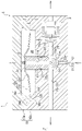
Fig. 1 is a cross-sectional view illustrating a pressure-reducing valve according to an embodiment of the present invention. -
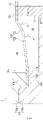
Fig. 2 is an enlarged cross-sectional view of one portion of a leaf spring in the pressure-reducing valve illustrated inFig. 1 . -
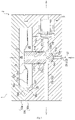
Fig. 3 is a cross-sectional view illustrating the pressure-reducing valve illustrated inFig. 1 with a valve body seated on a valve seat. -
Fig. 4 is an enlarged cross-sectional view of a portion of a pressure-reducing valve according to another embodiment that corresponds to a region X indicated inFig. 1 . - Hereinafter, a pressure-reducing valve 1, a valve unit 2, and a
leaf spring 12 according to an embodiment of the present invention will be described with reference to the aforementioned drawings. Note that the concept of directions mentioned in the following description is used for the sake of explanation; the orientations, etc., of elements according to the present invention are not limited to these directions. Each of the pressure-reducing valve 1 and theleaf spring 12 described below is merely one embodiment of the present invention. Thus, the present invention is not limited to the following embodiment and may be subject to addition, deletion, and alteration within the scope of the essence of the present invention. - The valve unit 2 illustrated in
Fig. 1 is used to reduce the pressure of gas such as compressed natural gas and hydrogen gas to the working pressure, the atmosphere pressure, or the like. The valve unit 2 includes the pressure-reducing valve 1 and arelief valve 3, for example. The pressure-reducing valve 1 includes a function of reducing the pressure of gas such as compressed natural gas and hydrogen gas to the working pressure, the atmosphere pressure, or the like. The pressure-reducing valve 1 includes acasing 10, avalve body 11, and theleaf spring 12. - The
casing 10 includes avalve passage 13 and asecondary chamber 26 therein. More specifically, thecasing 10 includes acover part 10a and ahousing block part 10b. In the present embodiment, thevalve passage 13 is formed in thehousing block part 10b. Thevalve passage 13 includes a primary-side passage 21, avalve chamber 22, and a secondary-side passage 23. Thevalve body 11 is inserted into thevalve chamber 22 in order to adjust the opening degree of the primary-side passage 21 (in other words, the opening degree of the valve passage 13). In thevalve passage 13, gas input to the primary-side passage 21 is output to the secondary-side passage 23 via thevalve chamber 22. - More specifically, the primary-
side passage 21 and thevalve chamber 22 are both formed along a predetermined axial line L1 and are connected to each other. In other words, the primary-side passage 21 is connected to the bottom of thevalve chamber 22. Furthermore, the secondary-side passage 23 is connected to the inner peripheral surface of thevalve chamber 22. The secondary-side passage 23 extends in a direction crossing the axial line L1. In the present embodiment, the secondary-side passage 23 extends in a direction orthogonal to the axial line L1. - The
valve body 11 is a circular cylindrical member formed of resin. Asealing member 27 is disposed between the outer peripheral surface of thevalve body 11 and the inner peripheral surface of the valve chamber 22 (specifically, thehousing block part 10b). Thevalve body 11 sealed by the sealingmember 27 is movably housed in thevalve chamber 22. In other words, thevalve body 11 can move towards and away from the primary-side passage 21 along the axial line L1. Furthermore, avalve seat part 24 is formed in thehousing block part 10b. Thevalve seat part 24 is formed around an opening 22a of thevalve chamber 22 on the primary-side passage 21 side. When a leadingend part 11a of thevalve body 11 is seated on thevalve seat part 24, the primary-side passage 21 is closed. The primary-side passage 21 can be opened by moving thevalve body 11 away from thevalve seat part 24. Accordingly, the primary-side passage 21 and the secondary-side passage 23 are connected via anannular passage 22c located around a leading end portion of thevalve body 11. Thus, in the pressure-reducing valve 1, thevalve passage 13 is closed by moving thevalve body 11 in one axial direction (namely, a closing direction) along the axial line L1. Furthermore, thevalve passage 13 is opened by moving thevalve body 11 in the other axial direction (namely, an opening direction) along the axial line L1. - The
leaf spring 12 is attached to thevalve body 11. Theleaf spring 12 can generate a restoring force corresponding to displacement. Furthermore, theleaf spring 12 moves thevalve body 11 with the generated restoring force. In the present embodiment, theleaf spring 12 is used instead of the helical compression spring. Theleaf spring 12, which is the biasing member, biases thevalve body 11 in the opening direction. More specifically, theleaf spring 12 is a metal member in the form of a plate (in the present embodiment, a member made of an alloy or a stainless steel (SUS) such as SUS304CSP). Theleaf spring 12 is formed in the shape of a circular disc when viewed in plan. Theleaf spring 12 has acenter portion 12a formed so as to have a cross-section rising in the one axial direction. Thecenter portion 12a of theleaf spring 12 is formed to be flat with a diameter greater than the outer diameter of thevalve body 11. - The base end surface of the
valve body 11 is attached to theleaf spring 12. In the present embodiment, the base end surface of thevalve body 11 is bonded to a surface of thecenter portion 12a that is located in the other axial direction. When the base end surface of thevalve body 11 is attached to theleaf spring 12, thevalve body 11 and theleaf spring 12 can be bonded together over a large surface area. - Note that examples of the attachment method includes a method in which surface treatment is applied to the surface located in the other axial direction and the
valve body 11 made of synthetic resin such as polyether ether ketone (PEEK), polyphenylene sulfide (PPS), polyimide (PI), and polyamide-imide (PAI) is formed by resin molding on said surface so that these are bonded together. Examples of the surface treatment includes chemical treatment and physical treatment involving laser irradiation. Other conceivable examples of the attachment method include attachment using a snap-fit, an adhesive, an adhesive tape, and a bush and attachment by way of chemical bonding, outsert molding, and the like. In these examples of the attachment method, it is preferred that the seal between thevalve body 11 and theleaf spring 12 be ensured using a sealing member or the like. - The
leaf spring 12 is fixed to thecasing 10. In the present embodiment, theleaf spring 12 is fixed to thecasing 10 by being sandwiched between thecover part 10a and thehousing block part 10b. More specifically, anouter edge portion 12b of theleaf spring 12 is formed to be flat. Thisouter edge portion 12b is fixed to thecasing 10. In other words, theouter edge portion 12b is sandwiched between thecover part 10a and thehousing block part 10b. - The outer edge of the
leaf spring 12 is placed on thehousing block part 10b. Astep part 10c is formed in thehousing block part 10b so as to fit with the outer edge of theouter edge portion 12b (in other words, the outer edge of the leaf spring 12). More specifically, thevalve chamber 22 is formed on one end surface of thehousing block part 10b along the axial line L1. Thestep part 10c having a diameter greater than the diameter of theleaf spring 12 is formed on one end surface of thehousing block part 10b. Theleaf spring 12 is disposed so that the outer edge thereof is placed on thestep part 10c. Furthermore, one end surface of thehousing block part 10b is covered by thecover part 10a. An annular protrudingpart 10d, which is in the form of a circular ring and fits with thestep part 10c, is formed on thecover part 10a. When the annular protrudingpart 10d fits on thestep part 10c, the outer edge is sandwiched between thestep part 10c and the annular protrudingpart 10d. Note that thestep part 10c and the annular protrudingpart 10d do not necessarily need to be provided and may be omitted. Furthermore, thestep part 10c does not necessarily need to be formed on thehousing block part 10b and may be formed on thecover part 10a. In this case, the annular protrudingpart 10d is formed on thehousing block part 10b. Thecover part 10a and thehousing block part 10b are fastened together using two or more fasteners that are bolts in the present embodiment, and the outer edge of theleaf spring 12 is sandwiched with the fastening force of the bolts. Note that thecover part 10a and thehousing block part 10b do not necessarily need to be fixed using the fasteners and may be screwed to each other. - Furthermore, in the
casing 10, thesecondary chamber 26 is formed in the one axial direction from theleaf spring 12. Moreover, anatmosphere chamber 28 is formed on the opposite side of theleaf spring 12 from thesecondary chamber 26, in other words, in the other axial direction from theleaf spring 12. In the present embodiment, thesecondary chamber 26 is enclosed by thecover part 10a and theleaf spring 12. More specifically, in thecover part 10a, arecess 10e is formed inward of the annular protrudingpart 10d. The space enclosed by therecess 10e and theleaf spring 12 forms thesecondary chamber 26. Theatmosphere chamber 28 is enclosed by thehousing block part 10b and theleaf spring 12. More specifically, in thehousing block part 10b, arecess 10f is formed inward of thestep part 10c. The space enclosed by therecess 10f and theleaf spring 12 forms theatmosphere chamber 28. - The
secondary chamber 26 is a chamber to which a secondary pressure is brought in order to exert the secondary pressure on thevalve body 11. Thesecondary chamber 26 is covered by theleaf spring 12. Therefore, theleaf spring 12 isolates thesecondary chamber 26 from theatmosphere chamber 28. In other words, when the outer edge of theleaf spring 12 is sandwiched between thestep part 10c and the annular protrudingpart 10d, a metal seal is formed between thestep part 10c and the annular protrudingpart 10d. With this, thesecondary chamber 26 is isolated from theatmosphere chamber 28. Furthermore, acommunication path 11b is formed in thevalve body 11. Thecommunication path 11b connects theannular passage 22c and thesecondary chamber 26. Therefore, the secondary pressure is brought to thesecondary chamber 26 through thecommunication path 11b. Furthermore, theleaf spring 12 can receive the secondary pressure brought to thesecondary chamber 26. This means that the secondary pressure can be exerted on thevalve body 11 via theleaf spring 12 in the closing direction. - The
leaf spring 12 is formed to protrude in the one axial direction (one direction), that is, in the opening direction, as mentioned earlier. Therefore, when thevalve body 11 moves in the other axial line, that is, in the closing direction, thevalve body 11 is biased in the opening direction for elastic recovery. Thus, thevalve body 11 receives, from theleaf spring 12, the biasing force acting against the aforementioned secondary pressure. Furthermore, the primary pressure in the primary-side passage 21 and the secondary pressure in theannular passage 22c act on thevalve body 11 in the opening direction. Therefore, thevalve body 11 moves to a position at which the received primary pressure, the received secondary pressure, and the received biasing force are balanced. Thus, by moving to the position corresponding to the secondary pressure, thevalve body 11 adjusts the opening degree of thevalve passage 13 and maintains the secondary pressure at a predetermined pressure. With theleaf spring 12 having such a function, because the leaf spring12 is a circular disc member protruding in the opening direction, the height of the spring can be less than that in the case where the helical compression spring is used. Therefore, it is possible to smoothly bias thevalve body 11 in the opening direction while minimizing the height of the pressure-reducing valve 1. Furthermore, in theleaf spring 12, atapered part 12c connecting theouter edge portion 12b and thecenter portion 12a is formed as follows. - Specifically, the
tapered part 12c is formed to be tapered in shape, as illustrated inFig. 2 . In the present embodiment, thetapered part 12c is formed to be tapered with more than one angle. Specifically, in thetapered part 12c, an outeredge side portion 12d and acenter side portion 12e have different taper angles α, β. Specifically, the taper angle β of thecenter side portion 12e is more acute than the taper angle α of the outeredge side portion 12d. Therefore, theleaf spring 12 has the outer edge thereof sandwiched when thevalve body 11 moves in the closing direction. Note that the taper angles α, β can be directly measured, but may be calculated using the angle formed between theouter edge portion 12b (flat portion) and the outeredge side portion 12d and the angle formed between theouter edge portion 12b (flat portion) and thecenter side portion 12e. - More specifically, when the
center portion 12a moves in the other axial direction, theleaf spring 12 bends as follows. Thetapered part 12c elastically deforms while changing the relative angle between the outeredge side portion 12d and thecenter side portion 12e, and moves thecenter portion 12a in parallel. Therefore, theleaf spring 12 can move thevalve body 11 substantially straight down in the closing direction and prevent the axis shift of the valve body 11 (the inclination of the valve body 11), thereby reducing partial contact of thevalve body 11 in thevalve chamber 22 during the movement of thevalve body 11 in the closing direction. Furthermore, when thetapered part 12c is formed, warping of theleaf spring 12 can be reduced. Thus, thevalve body 11 can be kept from becoming detached from theleaf spring 12. Note that in thetapered part 12c, the outeredge side portion 12d and thecenter side portion 12e do not necessarily need to have different taper angles and may be formed at a single taper angle. - The portion of the
leaf spring 12 that is located inward of theouter edge portion 12b protrudes from thestep part 10c to therecess 10f. Thus, it is possible to secure space for theleaf spring 12 to bend when thecenter portion 12a moves in the closing direction. Specifically, the portion inward of theouter edge portion 12b is allowed to bend toward therecess 10f (downward on the drawing sheet ofFig. 1 ), and theleaf spring 12 is allowed to deform until the outeredge side portion 12d of thetapered part 12c becomes substantially flush with theouter edge portion 12b. Therefore, it is possible to further minimize the height of theleaf spring 12 in the pressure-reducing valve 1 by designing theleaf spring 12 such that when thevalve body 11 is seated on thevalve seat part 24, the outeredge side portion 12d is substantially flush with theouter edge portion 12b, as illustrated inFig. 3 . - Furthermore, in the pressure-reducing valve 1, a relief port 22d is formed in the inner peripheral surface of the
valve chamber 22. In the present embodiment, the relief port 22d is formed in a position in which the opening of the secondary-side passage 23 is reflected across the axial line L1. Arelief passage 25 is connected to the relief port 22d. Therelief passage 25 extends orthogonally to the axial line L1. Therelief valve 3 is integrally provided in thecasing 10, and therelief passage 25 is connected to the atmosphere via therelief valve 3. When the secondary pressure at the pressure-reducing valve 1 exceeds a predetermined set pressure, therelief valve 3 drains the secondary pressure to the atmosphere and the like. When the relief port 22d is formed in the inner peripheral surface of thevalve chamber 22 as just described, therelief valve 3 can be disposed laterally to thevalve body 11. This makes it possible to minimize the axial length of the valve unit 2. - Furthermore, in the valve unit 2, an
open passage 29 is formed in thecasing 10. Theopen passage 29 allows communication between space on the secondary side of therelief valve 3 and theatmosphere chamber 28. More specifically, theatmosphere chamber 28 is isolated from thesecondary chamber 26 by theleaf spring 12, and is also isolated from theannular passage 22c by the sealingmember 27. Theopen passage 29 allows theatmosphere chamber 28 to communicate with the space on the secondary side of therelief valve 3. Therefore, even when theleaf spring 12 deforms and the volume of theatmosphere chamber 28 changes or when gas leaks into theatmosphere chamber 28, theatmosphere chamber 28 can be maintained at the atmospheric pressure. Furthermore, when the secondary pressure exceeds the set pressure and therelief valve 3 opens therelief passage 25, a relief pressure which is the pressure on the secondary side of therelief valve 3 is brought to theatmosphere chamber 28 through theopen passage 29. Thus, it is possible to exert the relief pressure on theleaf spring 12 against the secondary pressure. Therefore, it is possible to reduce load that acts on theleaf spring 12 when therelief valve 3 is actuated. - In the pressure-reducing valve 1 configured as described above, the
leaf spring 12 extends radially outward, in other words, laterally, from thevalve body 11. Therefore, the axial length of the pressure-reducing valve 1 can be set less than that of a conventional pressure-reducing valve; in other words, the pressure-reducing valve 1 can be downsized. Furthermore, in the pressure-reducing valve 1, theleaf spring 12 has a pressure-receiving function as mentioned above, and thus thevalve body 11 can be downsized and the number of components in thevalve body 11 can be reduced. Moreover, since theleaf spring 12 also has a sealing function, the number of components can be further reduced. Accordingly, the pressure-reducing valve 1 can be downsized. Furthermore, by using theleaf spring 12 as a seal, it is possible to reduce the number of slidable sealing members to be provided on thevalve body 11. This allows a reduction in sliding friction that acts on the valve body. Furthermore, by using theleaf spring 12 as a seal, it is possible to reduce the sliding friction. Moreover, in the pressure-reducing valve 1, since thevalve body 11 is formed of a resin member, the number of components can be small and it is easy to manufacture thevalve body 11, as compared to a pressure-reducing valve in which a portion to be seated on thevalve seat part 24 and the remaining portion are formed separately. Thus, the manufacturing cost of the pressure-reducing valve 1 can be reduced. - Although the present embodiment has described the case where the
leaf spring 12 is applied to the pressure-reducing valve 1, the valve device to which theleaf spring 12 is applied is not limited to the pressure-reducing valve 1. For example, the valve device may be replaced by an on-off valve, a relief valve, or the like; it is sufficient that the valve device bias the valve body in the opening or closing direction against gas pressures such as the primary pressure and the secondary pressure. Furthermore, theleaf spring 12 does not necessarily need to be attached to the end surface of thevalve body 11 and may be attached to the side surface of thevalve body 11 and moreover, the shape of theleaf spring 12 is not limited to the shape described above as long as theleaf spring 12 is in the form of a plate (for example, in the shape of a rectangle) extending laterally from thevalve body 11. Furthermore, theleaf spring 12 does not even necessarily need to have the pressure-receiving function or the sealing function, which may be achieved by thevalve body 11 or another member. Specifically, a pressure-receiving part may be formed on thevalve body 11 or an O-ring or a diaphragm may be used to achieve sealing. - Furthermore, sealing may be achieved using an O-
ring 15 as in a pressure-reducingvalve 1A illustrated inFig. 4 . Specifically, arecess 10g having an annular form is formed in the annular protrudingpart 10d, the O-ring 15 fits into therecess 10g, and the outer edge of theleaf spring 12 is sandwiched between thestep part 10c and the annular protrudingpart 10d together with the O-ring 15. With this, the sealing properties can be further improved. - Furthermore, the shape of the
valve passage 13 is also not limited to the shape described above. For example, the secondary-side passage 23 may be connected to thesecondary chamber 26. Furthermore, the position of therelief valve 3 is also not limited to the position described above and may be connected to the secondary-side passage 23. Furthermore, thecommunication path 11b illustrated inFig. 1 does not necessarily need to be formed in thevalve body 11 in order to bring the secondary pressure to thesecondary chamber 26. For example, a passage connecting the secondary-side passage 23 (or theannular passage 22c) and thesecondary chamber 26 may be formed in thecasing 10. The secondary-side passage 23 may be connected to thesecondary chamber 26 via a passage and external piping. Furthermore, theopen passage 29 does not necessarily need to be connected to therelief valve 3. This means that theopen passage 29 may be directly exposed to the atmosphere. - From the foregoing description, many modifications and other embodiments of the present invention would be obvious to a person having ordinary skill in the art. Therefore, the foregoing description should be interpreted only as an example and is provided for the purpose of teaching the best mode for carrying out the present invention to a person having ordinary skill in the art. Substantial changes in details of the structures and/or functions of the present invention are possible within the spirit of the present invention.
-
- 1
- pressure-reducing valve (valve device)
- 2
- valve unit
- 3
- relief valve
- 10
- casing
- 11
- valve body
- 12
- leaf spring (biasing member)
- 12a
- center portion
- 12b
- outer edge portion
- 12c
- tapered part
- 12d
- outer edge side portion
- 12e
- center side portion
- 13
- valve passage
- 22
- valve chamber
- 22d
- relief port
- 26
- secondary chamber
- 28
- atmosphere chamber
Claims (12)
- A pressure-reducing valve comprising:a casing in which a valve passage is formed;a valve body that is movably housed in the casing and changes a position thereof according to a secondary pressure to adjust an opening degree of the valve passage; anda biasing member that biases the valve body against the secondary pressure in an opening direction in which the valve passage opens, wherein:
the biasing member is a spring in the form of a plate and extends laterally from the valve body. - The pressure-reducing valve according to claim 1, wherein:the casing includes a secondary chamber into which the secondary pressure is brought, andthe biasing member covers the secondary chamber, receives the secondary pressure brought to the secondary chamber, and moves the valve body to a position corresponding to the secondary pressure received.
- The pressure-reducing valve according to claim 2, wherein:the casing includes a valve chamber that houses the valve body, andthe biasing member is provided in the casing to achieve sealing between the valve chamber and the secondary chamber.
- The pressure-reducing valve according to claim 1 or 2, wherein:the biasing member is a metal member; andthe valve body is a resin member.
- The pressure-reducing valve according to any one of claims 1 to 4, wherein:
the biasing member is formed in the shape of a circular disc protruding in the opening direction. - The pressure-reducing valve according to claim 5, wherein:
the biasing member includes a tapered part that is tapered in shape and connects an outer edge portion and a center portion, the outer edge portion being supported by the casing, the center portion being a portion to which the valve body is attached. - The pressure-reducing valve according to claim 6, wherein:
the tapered part is formed to cause a portion thereof that is close to the center portion to form a more acute angle than a portion thereof that is close to the outer edge portion. - The pressure-reducing valve according to any one of claims 1 to 7, wherein:in the casing, a relief port that relieves the secondary pressure is formed; andthe relief port is formed laterally to the valve body in the casing.
- A valve unit comprising:the pressure-reducing valve according to any one of claims 1 to 8; anda relief valve that relieves the secondary pressure at the pressure-reducing valve, wherein:in the pressure-reducing valve, an atmosphere chamber isolated from the secondary chamber and the valve passage is formed on an opposite side of the biasing member from the secondary chamber in the casing; andthe atmosphere chamber is exposed to an atmosphere via a secondary-side passage of the relief valve.
- A valve device comprising:a casing in which a valve passage is formed;a valve body that is movably housed in the casing and changes an opening degree of the valve passage according to a force acting thereon; anda biasing member that biases the valve body against the force acting on the valve body, wherein:
the biasing member is a spring in the form of a plate and extends laterally from the valve body. - A leaf spring for biasing a valve body in one direction, the leaf spring comprising:an inner portion to which the valve body is attached;an outer edge portion to be supported; anda tapered part that is tapered in shape and connects the inner portion and the outer edge portion.
- The leaf spring according to claim 11, wherein:
the tapered part is formed to cause a center side portion thereof to form a more acute angle than an outer edge side portion thereof.
Applications Claiming Priority (2)
| Application Number | Priority Date | Filing Date | Title |
|---|---|---|---|
| JP2020015831A JP7353197B2 (en) | 2020-01-31 | 2020-01-31 | Pressure reducing valve and valve unit |
| PCT/JP2021/001245 WO2021153272A1 (en) | 2020-01-31 | 2021-01-15 | Pressure reducing valve, valve unit, valve device, and plate spring |
Publications (3)
| Publication Number | Publication Date |
|---|---|
| EP4098917A1 true EP4098917A1 (en) | 2022-12-07 |
| EP4098917A4 EP4098917A4 (en) | 2024-05-22 |
| EP4098917B1 EP4098917B1 (en) | 2026-03-04 |
Family
ID=77078873
Family Applications (1)
| Application Number | Title | Priority Date | Filing Date |
|---|---|---|---|
| EP21747186.1A Active EP4098917B1 (en) | 2020-01-31 | 2021-01-15 | Pressure reducing valve, valve unit, valve device, and plate spring |
Country Status (6)
| Country | Link |
|---|---|
| US (1) | US11898650B2 (en) |
| EP (1) | EP4098917B1 (en) |
| JP (1) | JP7353197B2 (en) |
| KR (1) | KR102991603B1 (en) |
| CN (1) | CN114867958B (en) |
| WO (1) | WO2021153272A1 (en) |
Families Citing this family (2)
| Publication number | Priority date | Publication date | Assignee | Title |
|---|---|---|---|---|
| JP7819339B2 (en) * | 2022-10-18 | 2026-02-24 | 川崎重工業株式会社 | Pressure reducing valve and valve device |
| CN121399555A (en) * | 2023-06-27 | 2026-01-23 | 川崎重工业株式会社 | Pressure reducing valve |
Family Cites Families (24)
| Publication number | Priority date | Publication date | Assignee | Title |
|---|---|---|---|---|
| GB600030A (en) * | 1945-05-17 | 1948-03-30 | Frederick Benjamin Talley | Improvements in or relating to pressure reducing valves |
| JPS287358Y1 (en) * | 1952-03-05 | 1953-08-06 | ||
| FR2349084A1 (en) * | 1976-04-22 | 1977-11-18 | Proengin | Diaphragm actuated flow control valve - has plate spring to give accurate control at low flows |
| US4226257A (en) * | 1978-03-30 | 1980-10-07 | Sherwood-Selpac Corporation | Scuba regulator |
| JPS62113977A (en) * | 1985-11-13 | 1987-05-25 | Aisin Seiki Co Ltd | Solenoid valve |
| JPH01146076U (en) * | 1988-03-31 | 1989-10-06 | ||
| JP4016456B2 (en) | 1997-07-28 | 2007-12-05 | ソニー株式会社 | Cover body locking mechanism and recording and / or reproducing apparatus provided with the mechanism |
| JP2002023854A (en) * | 2000-07-07 | 2002-01-25 | Fujikura Rubber Ltd | Liquid pressure reducing valve |
| JP2003278928A (en) * | 2002-03-20 | 2003-10-02 | Toto Ltd | Pressure chamber type diaphragm valve |
| KR100576050B1 (en) * | 2004-03-29 | 2006-05-10 | 이종만 | Leaf springs and articles with them |
| JP4511489B2 (en) * | 2006-04-11 | 2010-07-28 | 日本精密測器株式会社 | Electric exhaust valve and blood pressure monitor |
| JP2009024780A (en) * | 2007-07-19 | 2009-02-05 | Inax Corp | Constant flow rate valve device |
| JP5202117B2 (en) * | 2008-06-10 | 2013-06-05 | 藤倉ゴム工業株式会社 | Pressure reducing valve |
| JP2010019353A (en) * | 2008-07-11 | 2010-01-28 | Kyosan Denki Co Ltd | Relief valve |
| JP5189542B2 (en) * | 2009-03-30 | 2013-04-24 | 株式会社ケーヒン | Gas pressure reducing valve |
| JP5462764B2 (en) | 2010-10-25 | 2014-04-02 | 川崎重工業株式会社 | Pressure reducing valve |
| JP2014058891A (en) * | 2012-09-18 | 2014-04-03 | Hitachi Automotive Systems Ltd | Pump device |
| JP6111862B2 (en) * | 2013-05-24 | 2017-04-12 | 日立金属株式会社 | Flow control valve and mass flow controller using the same |
| CN105144013B (en) * | 2013-10-21 | 2019-03-08 | 株式会社堀场Stec | Fluid Control Valve |
| EP2921762B1 (en) * | 2014-03-17 | 2017-08-02 | MAGNA STEYR Engineering AG & Co KG | Check valve |
| CN205136717U (en) * | 2015-11-18 | 2016-04-06 | 山西中煤华晋能源有限责任公司 | Pressure reducing valve |
| JP6755732B2 (en) * | 2016-07-07 | 2020-09-16 | 川崎重工業株式会社 | Pressure reducing valve |
| CN106931207A (en) * | 2017-03-23 | 2017-07-07 | 佛山吉宝信息科技有限公司 | A kind of novel fluid pressure maintaining valve |
| EP4040023B1 (en) * | 2019-10-02 | 2025-09-10 | SMC Corporation | High-pressure fluid discharge device |
-
2020
- 2020-01-31 JP JP2020015831A patent/JP7353197B2/en active Active
-
2021
- 2021-01-15 CN CN202180008142.0A patent/CN114867958B/en active Active
- 2021-01-15 KR KR1020227020759A patent/KR102991603B1/en active Active
- 2021-01-15 EP EP21747186.1A patent/EP4098917B1/en active Active
- 2021-01-15 US US17/759,496 patent/US11898650B2/en active Active
- 2021-01-15 WO PCT/JP2021/001245 patent/WO2021153272A1/en not_active Ceased
Also Published As
| Publication number | Publication date |
|---|---|
| CN114867958B (en) | 2025-12-23 |
| CN114867958A (en) | 2022-08-05 |
| EP4098917B1 (en) | 2026-03-04 |
| JP2021124130A (en) | 2021-08-30 |
| EP4098917A4 (en) | 2024-05-22 |
| KR102991603B1 (en) | 2026-07-15 |
| US11898650B2 (en) | 2024-02-13 |
| JP7353197B2 (en) | 2023-09-29 |
| KR20220130674A (en) | 2022-09-27 |
| WO2021153272A1 (en) | 2021-08-05 |
| US20230055857A1 (en) | 2023-02-23 |
Similar Documents
| Publication | Publication Date | Title |
|---|---|---|
| EP4098917B1 (en) | Pressure reducing valve, valve unit, valve device, and plate spring | |
| US20200063875A1 (en) | Two-way valve | |
| EP3008353B1 (en) | Actuator bushings having integral seals | |
| JP6321367B2 (en) | Pressure reducing valve | |
| JP5892543B2 (en) | Pressure reducing valve | |
| CN100541379C (en) | pressure reducer | |
| US10145481B2 (en) | Pneumatic valve | |
| US20190033899A1 (en) | Pressure regulator | |
| GB2298026A (en) | Pressure reducing valve | |
| EP4607312A1 (en) | Pressure reducing valve and valve device | |
| US7418973B2 (en) | Device to reduce noise in pressure regulators | |
| JP2001056059A (en) | Valve seal structure | |
| US20110048553A1 (en) | Pressure regulator | |
| JP5022971B2 (en) | Pressure regulator | |
| WO2025004906A1 (en) | Pressure reducing valve | |
| CN108603609A (en) | Diaphragm valve | |
| JP2007058616A (en) | Pressure regulator | |
| JP4164016B2 (en) | Gas regulator | |
| WO2010124722A1 (en) | A pressure regulator | |
| KR20230012754A (en) | Diaphragm valve | |
| JP2003156163A (en) | Packing check valve |
Legal Events
| Date | Code | Title | Description |
|---|---|---|---|
| STAA | Information on the status of an ep patent application or granted ep patent |
Free format text: STATUS: THE INTERNATIONAL PUBLICATION HAS BEEN MADE |
|
| PUAI | Public reference made under article 153(3) epc to a published international application that has entered the european phase |
Free format text: ORIGINAL CODE: 0009012 |
|
| STAA | Information on the status of an ep patent application or granted ep patent |
Free format text: STATUS: REQUEST FOR EXAMINATION WAS MADE |
|
| 17P | Request for examination filed |
Effective date: 20220831 |
|
| AK | Designated contracting states |
Kind code of ref document: A1 Designated state(s): AL AT BE BG CH CY CZ DE DK EE ES FI FR GB GR HR HU IE IS IT LI LT LU LV MC MK MT NL NO PL PT RO RS SE SI SK SM TR |
|
| DAV | Request for validation of the european patent (deleted) | ||
| DAX | Request for extension of the european patent (deleted) | ||
| RIC1 | Information provided on ipc code assigned before grant |
Ipc: F16K 27/02 20060101ALI20240125BHEP Ipc: G05D 16/10 20060101ALI20240125BHEP Ipc: G05D 16/06 20060101ALI20240125BHEP Ipc: F16K 17/30 20060101AFI20240125BHEP |
|
| A4 | Supplementary search report drawn up and despatched |
Effective date: 20240423 |
|
| RIC1 | Information provided on ipc code assigned before grant |
Ipc: F16K 27/02 20060101ALI20240417BHEP Ipc: G05D 16/10 20060101ALI20240417BHEP Ipc: G05D 16/06 20060101ALI20240417BHEP Ipc: F16K 17/30 20060101AFI20240417BHEP |
|
| STAA | Information on the status of an ep patent application or granted ep patent |
Free format text: STATUS: EXAMINATION IS IN PROGRESS |
|
| 17Q | First examination report despatched |
Effective date: 20250120 |
|
| GRAP | Despatch of communication of intention to grant a patent |
Free format text: ORIGINAL CODE: EPIDOSNIGR1 |
|
| STAA | Information on the status of an ep patent application or granted ep patent |
Free format text: STATUS: GRANT OF PATENT IS INTENDED |
|
| INTG | Intention to grant announced |
Effective date: 20250917 |
|
| GRAS | Grant fee paid |
Free format text: ORIGINAL CODE: EPIDOSNIGR3 |
|
| GRAA | (expected) grant |
Free format text: ORIGINAL CODE: 0009210 |
|
| STAA | Information on the status of an ep patent application or granted ep patent |
Free format text: STATUS: THE PATENT HAS BEEN GRANTED |
|
| AK | Designated contracting states |
Kind code of ref document: B1 Designated state(s): AL AT BE BG CH CY CZ DE DK EE ES FI FR GB GR HR HU IE IS IT LI LT LU LV MC MK MT NL NO PL PT RO RS SE SI SK SM TR |
|
| REG | Reference to a national code |
Ref country code: CH Ref legal event code: F10 Free format text: ST27 STATUS EVENT CODE: U-0-0-F10-F00 (AS PROVIDED BY THE NATIONAL OFFICE) Effective date: 20260304 Ref country code: GB Ref legal event code: FG4D |
|
| REG | Reference to a national code |
Ref country code: DE Ref legal event code: R096 Ref document number: 602021049259 Country of ref document: DE |
|
| REG | Reference to a national code |
Ref country code: IE Ref legal event code: FG4D |
|
| PG25 | Lapsed in a contracting state [announced via postgrant information from national office to epo] |
Ref country code: RS Free format text: LAPSE BECAUSE OF FAILURE TO SUBMIT A TRANSLATION OF THE DESCRIPTION OR TO PAY THE FEE WITHIN THE PRESCRIBED TIME-LIMIT Effective date: 20260604 |
|
| PG25 | Lapsed in a contracting state [announced via postgrant information from national office to epo] |
Ref country code: ES Free format text: LAPSE BECAUSE OF FAILURE TO SUBMIT A TRANSLATION OF THE DESCRIPTION OR TO PAY THE FEE WITHIN THE PRESCRIBED TIME-LIMIT Effective date: 20260304 |
|
| REG | Reference to a national code |
Ref country code: NL Ref legal event code: MP Effective date: 20260304 |
|
| PG25 | Lapsed in a contracting state [announced via postgrant information from national office to epo] |
Ref country code: PL Free format text: LAPSE BECAUSE OF FAILURE TO SUBMIT A TRANSLATION OF THE DESCRIPTION OR TO PAY THE FEE WITHIN THE PRESCRIBED TIME-LIMIT Effective date: 20260304 |
|
| PG25 | Lapsed in a contracting state [announced via postgrant information from national office to epo] |
Ref country code: GR Free format text: LAPSE BECAUSE OF FAILURE TO SUBMIT A TRANSLATION OF THE DESCRIPTION OR TO PAY THE FEE WITHIN THE PRESCRIBED TIME-LIMIT Effective date: 20260605 |
|
| REG | Reference to a national code |
Ref country code: LT Ref legal event code: MG9D |
|
| PG25 | Lapsed in a contracting state [announced via postgrant information from national office to epo] |
Ref country code: LT Free format text: LAPSE BECAUSE OF FAILURE TO SUBMIT A TRANSLATION OF THE DESCRIPTION OR TO PAY THE FEE WITHIN THE PRESCRIBED TIME-LIMIT Effective date: 20260304 |
|
| PG25 | Lapsed in a contracting state [announced via postgrant information from national office to epo] |
Ref country code: NO Free format text: LAPSE BECAUSE OF FAILURE TO SUBMIT A TRANSLATION OF THE DESCRIPTION OR TO PAY THE FEE WITHIN THE PRESCRIBED TIME-LIMIT Effective date: 20260604 |
|
| PG25 | Lapsed in a contracting state [announced via postgrant information from national office to epo] |
Ref country code: FI Free format text: LAPSE BECAUSE OF FAILURE TO SUBMIT A TRANSLATION OF THE DESCRIPTION OR TO PAY THE FEE WITHIN THE PRESCRIBED TIME-LIMIT Effective date: 20260304 Ref country code: SE Free format text: LAPSE BECAUSE OF FAILURE TO SUBMIT A TRANSLATION OF THE DESCRIPTION OR TO PAY THE FEE WITHIN THE PRESCRIBED TIME-LIMIT Effective date: 20260304 |
|
| PG25 | Lapsed in a contracting state [announced via postgrant information from national office to epo] |
Ref country code: HR Free format text: LAPSE BECAUSE OF FAILURE TO SUBMIT A TRANSLATION OF THE DESCRIPTION OR TO PAY THE FEE WITHIN THE PRESCRIBED TIME-LIMIT Effective date: 20260304 |
|
| PG25 | Lapsed in a contracting state [announced via postgrant information from national office to epo] |
Ref country code: LV Free format text: LAPSE BECAUSE OF FAILURE TO SUBMIT A TRANSLATION OF THE DESCRIPTION OR TO PAY THE FEE WITHIN THE PRESCRIBED TIME-LIMIT Effective date: 20260304 |
|
| PG25 | Lapsed in a contracting state [announced via postgrant information from national office to epo] |
Ref country code: BG Free format text: LAPSE BECAUSE OF FAILURE TO SUBMIT A TRANSLATION OF THE DESCRIPTION OR TO PAY THE FEE WITHIN THE PRESCRIBED TIME-LIMIT Effective date: 20260304 |