EP4098813A1 - Working machine - Google Patents
Working machine Download PDFInfo
- Publication number
- EP4098813A1 EP4098813A1 EP21875772.2A EP21875772A EP4098813A1 EP 4098813 A1 EP4098813 A1 EP 4098813A1 EP 21875772 A EP21875772 A EP 21875772A EP 4098813 A1 EP4098813 A1 EP 4098813A1
- Authority
- EP
- European Patent Office
- Prior art keywords
- working
- working device
- monitor
- stress
- physical quantity
- Prior art date
- Legal status (The legal status is an assumption and is not a legal conclusion. Google has not performed a legal analysis and makes no representation as to the accuracy of the status listed.)
- Granted
Links
Images


Classifications
-
- E—FIXED CONSTRUCTIONS
- E02—HYDRAULIC ENGINEERING; FOUNDATIONS; SOIL SHIFTING
- E02F—DREDGING; SOIL-SHIFTING
- E02F9/00—Component parts of dredgers or soil-shifting machines, not restricted to one of the kinds covered by groups E02F3/00 - E02F7/00
- E02F9/26—Indicating devices
- E02F9/267—Diagnosing or detecting failure of vehicles
-
- E—FIXED CONSTRUCTIONS
- E02—HYDRAULIC ENGINEERING; FOUNDATIONS; SOIL SHIFTING
- E02F—DREDGING; SOIL-SHIFTING
- E02F9/00—Component parts of dredgers or soil-shifting machines, not restricted to one of the kinds covered by groups E02F3/00 - E02F7/00
- E02F9/26—Indicating devices
- E02F9/264—Sensors and their calibration for indicating the position of the work tool
-
- E—FIXED CONSTRUCTIONS
- E02—HYDRAULIC ENGINEERING; FOUNDATIONS; SOIL SHIFTING
- E02F—DREDGING; SOIL-SHIFTING
- E02F3/00—Dredgers; Soil-shifting machines
- E02F3/04—Dredgers; Soil-shifting machines mechanically-driven
- E02F3/28—Dredgers; Soil-shifting machines mechanically-driven with digging tools mounted on a dipper- or bucket-arm, i.e. there is either one arm or a pair of arms, e.g. dippers, buckets
- E02F3/36—Component parts
- E02F3/42—Drives for dippers, buckets, dipper-arms or bucket-arms
- E02F3/43—Control of dipper or bucket position; Control of sequence of drive operations
- E02F3/435—Control of dipper or bucket position; Control of sequence of drive operations for dipper-arms, backhoes or the like
-
- E—FIXED CONSTRUCTIONS
- E02—HYDRAULIC ENGINEERING; FOUNDATIONS; SOIL SHIFTING
- E02F—DREDGING; SOIL-SHIFTING
- E02F9/00—Component parts of dredgers or soil-shifting machines, not restricted to one of the kinds covered by groups E02F3/00 - E02F7/00
- E02F9/20—Drives; Control devices
- E02F9/2025—Particular purposes of control systems not otherwise provided for
- E02F9/2054—Fleet management
Definitions
- the present invention relates to a working machine, and more particularly to a technique for reducing damage to a working device.
- Patent Document 1 Japanese Patent Laid-Open No. 2014-222003
- Patent Document 1 Although it is possible to predict a failure of the working device earlier than expected and to take measures such as replacement of the working device, it is not possible to reduce fatigue itself accumulated in the working device. Therefore, in order to reduce the fatigue of the working device, it has been necessary to reduce stress applied to the working device by improving the skills of operators or by equalizing the skills.
- the present invention is made in consideration of such problems, and its object is to provide a working machine capable of specifically recognizing the relationship between stress applied to a working device and a movement of a machine body.
- an aspect of the present invention is directed to a working machine equipped with a working device that extends to the outside of a machine body, the working machine including: a physical quantity detection sensor that detects a physical quantity concerning the working machine; a monitor that displays predetermined information; and a controller that controls the monitor.
- the controller includes a stress calculation section that calculates a distribution of stress applied to the working device based on the physical quantity concerning the working machine, detected by the physical quantity detection sensor, and a display control section that controls the display of the predetermined information on the monitor.
- the display control section controls the display on the monitor so as to indicate the distribution of the stress applied to the working device, calculated by the stress calculation section, in conjunction with a movement of the working device.
- the operator can understand in a physical sense that the operation is such that fatigue accumulates in the working device because the distribution of the stress applied to the working device moved by the operation of the machine body by the operator is displayed on the monitor in conjunction with the movement of the working device.
- the display of the predetermined information controlled by the display control section includes a simulated view obtained by simulating the working device, and the simulated view indicates the distribution of the stress applied to the working device, calculated by the stress calculation section, in conjunction with a movement of the working device.
- the working machine further includes an attitude calculation section that calculates an attitude of the working device based on the physical quantity concerning the working machine, detected by the physical quantity detection sensor, and the simulated view is a pseudo image in which the attitude of the working device calculated by the attitude calculation section is in conjunction with the movement of the working device.
- the stress distribution being in conjunction with the movement of the working device is displayed in the pseudo image being in conjunction with the attitude of the working device calculated by the attitude calculation section, whereby the attitude of the working device and the stress distribution can be visually recognized simultaneously.
- the working machine further includes an imaging device that images the working device, the display of the predetermined information includes an image of the working device captured by the imaging device, and the stress distribution and the image of the working device indicated in the simulated view are in conjunction with the movement of the working device.
- the distribution of the stress applied to the working device can be recognized while the captured image of the actual working device is compared with the simulated view.
- the machine body is provided with an operating cabin where an operator for operating the machine body rides, and the monitor is disposed in the operating cabin.
- the operator can visually recognize the monitor while operating the machine body, to understand in a physical sense whether or not his or her operation is an operation such that fatigue accumulates in the working device.
- the working machine further includes a communication device that performs wireless communication between the machine body and the monitor, and the monitor is provided separately from the machine body.
- the distribution of the stress applied to the working device can be recognized at a place away from the machine body, such as a remote location.
- the working machine of the present invention by indicating on the monitor the distribution of the stress applied to the working device, calculated by the stress calculation section, in conjunction with the movement of the working device, when the operation of the machine body by an operator is an operation such that fatigue accumulates in the working device, the operator can understand in a physical sense that the operation is such that fatigue accumulates in the working device because the distribution of the stress applied to the working device moved by the operation of the machine body by the operator is displayed in conjunction with the movement of the working device. It is thereby possible to specifically recognize the relationship between the stress applied to the working device and the movement of the machine body.
- FIG. 1 a side view of a hydraulic excavator (machine body, working machine) 1 according to the first embodiment is illustrated.
- the hydraulic excavator 1 is a large hydraulic excavator operated at a site such as a mine and is, for example, a machine having a maximum front-rear length of 25 m, a maximum left-right length of 7 m, and a maximum height of 15 m from the ground.
- the hydraulic excavator 1 is normally operated 24 hours a day with three to four operators taking turns each day.
- This hydraulic excavator 1 is provided with a lower traveling body 2, an upper rotary body 3, and a rotating device 4.
- the lower traveling body 2 is a traveling device of the hydraulic excavator 1, and a crawler-type lower traveling body 2 is exemplified here.
- the upper rotary body 3 is coupled to the lower traveling body 2 via a rotary frame 3a and the rotating device 4 which form the lower skeleton of the upper rotary body 3.
- the rotating device 4 is a device capable of rotating the upper rotary body 3 relative to the lower traveling body 2.
- the rotating device 4 has a rotary bearing (not illustrated) provided therein, and by the driving of a rotating hydraulic motor (not illustrated), the rotating device 4 can perform a rotating movement to rotate the upper rotary body 3 around the rotary bearing.
- an operating cabin 5 In the upper rotary body 3, an operating cabin 5, a front attachment (working device) 7, a housing 6, and the like are mounted on the rotary frame 3a.
- the operating cabin 5 is provided with various operating devices for operating the hydraulic excavator 1.
- the operator can perform various operations of the hydraulic excavator 1, such as a rotating operation for operating the rotating device 4 and a work operation for operating the front attachment 7.
- the housing 6 houses machines such as an engine and a hydraulic pump (not illustrated) and is disposed behind the operating cabin 5.
- the front attachment 7 is provided at the front center of the upper rotary body 3 and includes a boom 10, an arm 11, and a bucket 12.
- the base end of the boom 10 is axially supported by a coupling pin (not illustrated) on the rotary frame 3a.
- the boom 10 is swingable relative to the rotary frame 3a.
- the arm 11 is coupled to the front end of the boom 10 so as to be rotationally movable in the vertical direction
- the bucket 12 is coupled to the front end of the arm 11 so as to be rotationally movable in the vertical direction.
- a boom cylinder 10a is adjusted by hydraulic pressure for expansion and contraction to make the boom 10 movable rotationally.
- an arm cylinder 11a is adjusted by hydraulic pressure for expansion and contraction to make the arm 11 movable rotationally
- a bucket cylinder 12a is adjusted by hydraulic pressure for expansion and contraction to make the bucket 12 movable rotationally. Therefore, the front attachment 7 can appropriately adjust the boom cylinder 10a, the arm cylinder 11a, and the bucket cylinder 12a for expansion and contraction, thereby rotationally moving the boom 10, the arm 11, and the bucket 12 as appropriate to perform work and movements such as an excavating movement, which will be described later.
- the front attachment 7 is provided with a plurality of sensors for detecting various physical quantities.
- a boom pressure sensor 10b is provided in the boom cylinder 10a
- an arm pressure sensor 11b is provided in the arm cylinder 11a
- a bucket pressure sensor 12b is provided in the bucket cylinder 12a.
- These pressure sensors are capable of detecting pressures in the respective cylinders.
- the boom pressure sensor 10b, the arm pressure sensor 11b, and the bucket pressure sensor 12b are collectively referred to as a cylinder pressure sensor 15.
- a first goniometer 21, a second goniometer 22, and a third goniometer 23 are provided at the coupling portions of the rotary frame 3a, the boom 10, the arm 11, and the bucket 12.
- the first goniometer 21 is a sensor for detecting a relative angle between the rotary frame 3a and the boom 10.
- the second goniometer 22 is a sensor for detecting a relative angle between the boom 10 and the arm 11.
- the third goniometer 23 is a sensor for detecting a relative angle between the arm 11 and the bucket 12.
- the first goniometer 21, the second goniometer 22, and the third goniometer 23 are collectively referred to as a front goniometer 25.
- the upper rotary body 3, the rotating device 4, and the housing 6 are provided with a vehicle body inclination goniometer 31, a rotation goniometer 33, a hydraulic oil thermometer 35, an engine tachometer 36, a hydraulic pump discharge pressure gauge 37, a hydraulic motor inlet pressure gauge 38, and an accelerometer 39.
- the vehicle body inclination goniometer 31 is a sensor for detecting an inclination angle indicating the inclination of the hydraulic excavator 1 in the front-rear and left-right directions.
- the rotation goniometer 33 is a sensor for detecting a relative angle between the upper rotary body 3 and the lower traveling body 2.
- the hydraulic oil thermometer 35 is a sensor for detecting the temperature of hydraulic oil that is supplied to a hydraulic motor, a hydraulic cylinder, and the like by a hydraulic pump (not illustrated).
- the engine tachometer 36 is a rotation sensor for detecting the rotational speed of the engine (not illustrated).
- the hydraulic pump discharge pressure gauge 37 is a pressure sensor for detecting the pressure of the hydraulic oil supplied from the hydraulic pump (not illustrated) to the hydraulic motor, the hydraulic cylinder, and the like.
- the hydraulic motor inlet pressure gauge 38 is a pressure sensor for detecting the pressure of hydraulic oil supplied to the rotating hydraulic motor (not illustrated) and the like.
- the accelerometer 39 is an acceleration sensor for detecting the acceleration of vibration generated in the upper rotary body 3 and the lower traveling body 2.
- the operating cabin 5 is provided with a camera 41 and a monitor 43.
- the camera 41 is installed in the operating cabin 5, for example, and is an imaging device for imaging the front of the operating cabin 5.
- On the monitor 43 various kinds of information on the hydraulic excavator 1, such as the state and attitude of the hydraulic excavator 1, are displayed. Note that the information displayed on the monitor 43 will be described later.
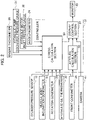
- the controller 51 is a control device for performing the comprehensive control of the hydraulic excavator 1 including the operation control of the engine, and the controller 51 includes an input/output device, a storage device (read-only memory (ROM), random-access memory (RAM), non-volatile RAM, etc.), a central processing unit (CPU), and the like and is disposed in the operating cabin 5 of the upper rotary body 3, for example.
- ROM read-only memory
- RAM random-access memory
- CPU central processing unit
- the camera (imaging device) 41 and sensors (physical quantity detection sensors) for detecting physical quantities concerning the machine body 1 are electrically connected to the input side of the controller 51, the sensors being the cylinder pressure sensor 15, the front goniometer 25, the vehicle body inclination goniometer 31, the rotation goniometer 33, the hydraulic oil thermometer 35, the engine tachometer 36, the hydraulic pump discharge pressure gauge 37, the hydraulic motor inlet pressure gauge 38, the accelerometer 39, and the like.
- information on the inclination angle of the hydraulic excavator 1 is input from the vehicle body inclination goniometer 31
- information on the relative angle between the upper rotary body 3 and the lower traveling body 2 is input from the rotation goniometer 33
- information on the temperature of the hydraulic oil is input from the hydraulic oil thermometer 35.
- information on the engine rotational speed is input from the engine tachometer 36
- information on the pressure of the hydraulic oil supplied from the hydraulic pump to the hydraulic motor, the hydraulic cylinder, and the like is input from the hydraulic pump discharge pressure gauge 37
- information on the pressure of the hydraulic oil supplied to the rotating hydraulic motor and the like is input from the hydraulic motor inlet pressure gauge 38
- information on the acceleration of vibration generated in the upper rotary body 3 and the lower traveling body 2 is input from the accelerometer 39
- information on the image of the front of the operating cabin 5 is input from the camera 41.
- the monitor 43 is electrically connected to the output side of the controller 51, and by controlling the monitor 43, various kinds of information on the hydraulic excavator 1 can be reported to the operator who rides in the operating cabin 5.
- the information may be input and output between each sensor and the controller 51 via a network such as a control area network (CAN) or a local area network (LAN).
- CAN control area network
- LAN local area network
- the controller 51 includes a stress calculation section 53, an attitude calculation section 55, and a display control section 57.
- the stress calculation section 53 is a calculation section capable of calculating a stress distribution applied to the front attachment 7. Specifically, the stress calculation section 53 calculates a stress distribution generated at each position of the front attachment 7 by using a numerical analysis method, such as the finite element method, or a statistical method, such as regression analysis, based on the information on the physical quantity input from each of the cylinder pressure sensor 15, the front goniometer 25, the vehicle body inclination goniometer 31, the rotation goniometer 33, the hydraulic oil thermometer 35, the engine tachometer 36, the hydraulic pump discharge pressure gauge 37, the hydraulic motor inlet pressure gauge 38, and the accelerometer 39. Further, the stress calculation section 53 calculates the stress distribution at least every time the information on the physical quantity changes.
- the attitude calculation section 55 is a calculation section capable of calculating the attitude of the front attachment 7 based on the information on the relative angle at each of the coupling portions of the rotary frame 3a, the boom 10, the arm 11, and the bucket 12, which are input from the front goniometer 25.
- the attitude calculation section 55 calculates the attitude of the front attachment 7 every time the information on the relative angle at each coupling portion input from the front goniometer 25 changes.
- the display control section 57 is a control section that controls display on the monitor 43 based on the stress distribution calculated by the stress calculation section 53, the attitude of the front attachment 7 calculated by the attitude calculation section 55, and the image in front of the operating cabin 5 captured by the camera 41.
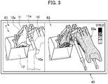
- FIG. 3 an explanatory diagram for explaining information displayed on the monitor 43 according to the first embodiment is illustrated.
- a front image 61 an image of the front of the operating cabin 5 captured by the camera 41
- a perspective view of the front attachment 7 hereinafter referred to as a pseudo image 63
- the pseudo image 63 is a view representing a simulated three-dimensional perspective view of the front attachment 7 so as to have the attitude of the front attachment 7 calculated by the attitude calculation section 55, for example.
- This pseudo image 63 is a perspective view when viewed from a direction corresponding to a direction in which the camera 41 images the front attachment 7.
- a stress distribution 63a calculated by the stress calculation section 53 is shown in, for example, four stages such that the higher the stress, the darker the color. Note that the color may be changed in accordance with the degree of stress.
- the attitude calculation section 55 calculates the attitude of the front attachment 7 every time the information on the relative angle in each coupling portion input from the front goniometer 25 changes
- the stress calculation section 53 calculates the stress distribution 63a every time the information on the physical quantity input from each of the cylinder pressure sensor 15, the front goniometer 25, the vehicle body inclination goniometer 31, the rotation goniometer 33, the hydraulic oil thermometer 35, the engine tachometer 36, the hydraulic pump discharge pressure gauge 37, the hydraulic motor inlet pressure gauge 38, and the accelerometer 39 changes, so that the operator can recognize the stress distribution 63a of the front attachment 7 which changes according to the operation of the hydraulic excavator 1 simultaneously with the operation in what is called real time. Further, the operator can compare the front image 61 and the pseudo image 63 to easily recognize the stress distribution 63a in the front attachment 7.
- the working machine according to the first embodiment equipped with the front attachment 7 that extends to the outside of the hydraulic excavator includes: the sensors for detecting physical quantities, such as the cylinder pressure sensor 15, the front goniometer 25, the vehicle body inclination goniometer 31, the rotation goniometer 33, the hydraulic oil thermometer 35, the engine tachometer 36, the hydraulic pump discharge pressure gauge 37, the hydraulic motor inlet pressure gauge 38, and the accelerometer 39; the monitor 43 for displaying predetermined information such as the front image 61 and the pseudo image 63; and the controller 51 for controlling the monitor 43.
- the sensors for detecting physical quantities such as the cylinder pressure sensor 15, the front goniometer 25, the vehicle body inclination goniometer 31, the rotation goniometer 33, the hydraulic oil thermometer 35, the engine tachometer 36, the hydraulic pump discharge pressure gauge 37, the hydraulic motor inlet pressure gauge 38, and the accelerometer 39
- the monitor 43 for displaying predetermined information such as the front image 61 and the pseudo image 63
- the controller 51 for controlling the
- the controller 51 includes: the stress calculation section 53 for calculating the stress distribution 63a, which is a distribution of stress applied to the front attachment 7, based on the physical quantities detected by the sensors, such as the cylinder pressure sensor 15, the front goniometer 25, the vehicle body inclination goniometer 31, the rotation goniometer 33, the hydraulic oil thermometer 35, the engine tachometer 36, the hydraulic pump discharge pressure gauge 37, the hydraulic motor inlet pressure gauge 38, and the accelerometer 39; and the display control section 57 for controlling the display of the predetermined information on the monitor 43.
- the sensors such as the cylinder pressure sensor 15, the front goniometer 25, the vehicle body inclination goniometer 31, the rotation goniometer 33, the hydraulic oil thermometer 35, the engine tachometer 36, the hydraulic pump discharge pressure gauge 37, the hydraulic motor inlet pressure gauge 38, and the accelerometer 39
- the display control section 57 for controlling the display of the predetermined information on the monitor 43.
- the display control section 57 controls the display on the monitor 43 so as to indicate the stress distribution 63a in the front attachment 7, calculated by the stress calculation section 53, in conjunction with the movement of the front attachment 7.
- the display of the predetermined information which is controlled by the display control section 57 and displayed on the monitor 43, includes a simulated view obtained by simulating the front attachment 7, and the simulated view indicates the stress distribution 63a calculated by the stress calculation section 53 on the monitor 43 in conjunction with the movement of the front attachment 7, so that it is possible to visually and easily understand whether or not the operation of the hydraulic excavator 1 by the operator is an operation such that fatigue accumulates in the front attachment 7.
- the attitude calculation section 55 is provided to calculate the attitude of the front attachment 7 based on the physical quantities detected by the sensors such as the cylinder pressure sensor 15, the front goniometer 25, the vehicle body inclination goniometer 31, the rotation goniometer 33, the hydraulic oil thermometer 35, the engine tachometer 36, the hydraulic pump discharge pressure gauge 37, the hydraulic motor inlet pressure gauge 38, and the accelerometer 39, and the pseudo image 63 in which the attitude of the front attachment 7 calculated by the attitude calculation section 55 is in conjunction with the movement of the front attachment 7 is displayed as a simulated view, so that the attitude of the front attachment 7 and the stress distribution 63a can be visually recognized simultaneously.
- the sensors such as the cylinder pressure sensor 15, the front goniometer 25, the vehicle body inclination goniometer 31, the rotation goniometer 33, the hydraulic oil thermometer 35, the engine tachometer 36, the hydraulic pump discharge pressure gauge 37, the hydraulic motor inlet pressure gauge 38, and the accelerometer 39, and the pseudo image 63 in which the attitude of the front attachment 7 calculated
- the camera 41 for imaging the front attachment 7 is provided, the display of the predetermined information includes the front image 61 captured by the camera 41, and the stress distribution 63a of the pseudo image 63 and the front image 61 are in conjunction with the movement of the front attachment 7, so that the stress distribution 63a of the front attachment 7 can be recognized while the front image 61, which is an image of the actual front attachment 7, is compared with the pseudo image 63, which is a simulated view.
- the hydraulic excavator 1 is provided with the operating cabin 5 where the operator for operating the hydraulic excavator 1 rides, and the monitor 43 is disposed in the operating cabin 5, so that the operator can visually recognize the monitor 43 while operating the hydraulic excavator 1, to understand in a physical sense whether or not his or her operation is an operation such that fatigue accumulates in the front attachment 7.
- a connection configuration of a controller 151 according to the control of the second embodiment is illustrated in a block diagram.
- the controller 151 according to the second embodiment differs in that a communication device 160 is connected instead of the monitor 43 electrically connected to the output side of the controller 51 according to the first embodiment.
- the communication device 160 includes a first communication device 161 and a second communication device 162, and the first communication device 161 and the second communication device 162 can wirelessly transmit and receive information to and from each other.
- the first communication device 161 is disposed in the hydraulic excavator 1
- the second communication device 162 is disposed in, for example, a management center (remote location) 100 for managing the hydraulic excavator 1.
- a management center 100 a personal computer (PC) 143 for managing the operation of the hydraulic excavator 1, the state of the hydraulic excavator 1, and the like is disposed, and the PC 143 is electrically connected to the second communication device 162 so as to be able to input and output information.
- PC personal computer
- the controller 151 according to the second embodiment corresponds to the controller 51 according to the first embodiment, and the display control section 57 forms images similar to the front image 61 and the pseudo image 63.
- the controller 151 transmits the front image 61 and the pseudo image 63 to the PC 143 via the communication device 160. Then, the PC 143 displays the front image 61 and the pseudo image 63 on the screen.
- the images thus displayed on the PC 143 can be viewed by, for example, a skilled person located at the management center 100 or an operator who remotely operates the hydraulic excavator 1 from the management center 100. Therefore, based on the image displayed on the PC 143, the skilled person can instruct an operator riding on the hydraulic excavator 1 and performing the operation on an appropriate operation method of the hydraulic excavator 1 from the management center 100, and the operator who remotely operates the hydraulic excavator 1 can improve the operation technique of the hydraulic excavator 1 by himself or herself.
- the working machine has the communication device 160 that performs wireless communication between the hydraulic excavator 1 and the PC 143, and the PC 143 is provided separately from the hydraulic excavator 1, so that the stress distribution 63a of the front attachment 7 can be recognized at a place away from the hydraulic excavator 1 such as the management center 100. Further, based on the stress distribution 63a of the front attachment 7 thus recognized, the operator can improve the operation technique of the hydraulic excavator 1.
- a working machine including a working device such as a wheel loader may be used.
- the stress calculation section 53 has calculated the stress distribution 63a of the front attachment 7 based on the information input from each of the cylinder pressure sensor 15, the front goniometer 25, the vehicle body inclination goniometer 31, the rotation goniometer 33, the hydraulic oil thermometer 35, the engine tachometer 36, the hydraulic pump discharge pressure gauge 37, the hydraulic motor inlet pressure gauge 38, and the accelerometer 39.
- a sensor other than these sensors may be used, or some of these sensors may not be used, so long as the stress distribution 63a can be calculated based on the physical quantity applied to the front attachment 7.
- the numerical analysis method such as the finite element method, or the statistical method, such as regression analysis, is used as the method for calculation of the stress distribution 63a by the stress calculation section 53.
- the numerical analysis method such as the finite element method, or the statistical method, such as regression analysis
- other calculation methods may be used so long as the stress distribution 63a of the front attachment 7 can be calculated.
- the inside of the operating cabin 5 has been exemplified as the place for installation of the imaging device that images the front of the operating cabin 5, but the imaging device may be installed in the upper rotary body 3 outside the operating cabin or may be installed at a position away from the machine body.
- the pseudo image 63 of the three-dimensional perspective view has been used as the simulated view, but other simulated views such as a net view and a six view may be used.
- the stress distribution 63a may be displayed so as to be superimposed on the front image 61.
- the front image 61 and the pseudo image 63 have been displayed side-by-side on the left and right on the monitor 43, but only the pseudo image 63 may be displayed.
- one set of the front image 61 superimposed on the stress distribution 63a may be made, and two or more sets of the past set and the present set may be simultaneously arranged and displayed in comparison with each other on the monitor 43.
- the description has been given using the PC 143 disposed in the management center 100, but the front image 61 and the pseudo image 63 may be displayed on a tablet terminal, and the tablet terminal may be used at a corner of the work site where the hydraulic excavator 1 can be observed visually.
- the display control section 57 of the controller 151 disposed in the hydraulic excavator 1 forms images similar to the front image 61 and the pseudo image 63, but the display control section 57, the stress calculation section 53, and the attitude calculation section 55 may be disposed in the PC 143 to form images on the management center 100 side.
- the information from each sensor or the camera 41 may be transmitted to the PC 143 via the communication device 160.
- the front image 61 and the pseudo image 63 have been displayed on the PC 143, but a microphone may be disposed in the hydraulic excavator 1 to acquire sound information, and the operator who remotely operates the hydraulic excavator 1 at the management center 100 is caused to recognize a sound similar to that acquired when the operator is riding on the hydraulic excavator 1.
Landscapes
- Engineering & Computer Science (AREA)
- Mining & Mineral Resources (AREA)
- Civil Engineering (AREA)
- General Engineering & Computer Science (AREA)
- Structural Engineering (AREA)
- Component Parts Of Construction Machinery (AREA)
- Operation Control Of Excavators (AREA)
Abstract
Description
- The present invention relates to a working machine, and more particularly to a technique for reducing damage to a working device.
- In working machines such as construction machines, a great amount of stress may be generated in a working device having structures such as a boom and an arm due to excavation or other work. Especially in a portion where stress is concentrated, fatigue is considered to accumulate and cause a failure. When the working machine must be stopped due to such a failure of the working device, productivity and the like are affected, and it is thus necessary to predict the failure in advance.
- Therefore, there has been developed a technique capable of making an appropriate work plan and maintenance plan for a hydraulic excavator in such a manner that based on data representing distributions of damage degrees (fatigue) accumulated in a component of the working machine under a plurality of operating conditions, distributions of fatigue accumulated in the component of the working machine are displayed for respective operating conditions as images on a display screen in a state where the distributions can be compared with each other (Patent Document 1).
- Patent Document 1:
Japanese Patent Laid-Open No. 2014-222003 - However, according to the technique disclosed in
Patent Document 1, although it is possible to predict a failure of the working device earlier than expected and to take measures such as replacement of the working device, it is not possible to reduce fatigue itself accumulated in the working device. Therefore, in order to reduce the fatigue of the working device, it has been necessary to reduce stress applied to the working device by improving the skills of operators or by equalizing the skills. - For improving the skills of the operators or to equalizing the skills, it is effective for an operator with high skill (skilled person) to instruct an operator with low skill (skill-developing person). However, during the instruction, conveying abstract information such as the image and sense of excavation that the skilled person recognizes empirically, like the sounds of an engine and hydraulic equipment, changes in vibration, and the like, to the skill-developing person does not make it possible for the skill-developing person to satisfactorily recognize the relationship between damage to the working device and the movement of the machine body, and there has been room for further improvement.
- The present invention is made in consideration of such problems, and its object is to provide a working machine capable of specifically recognizing the relationship between stress applied to a working device and a movement of a machine body.
- In order to achieve the above object, an aspect of the present invention is directed to a working machine equipped with a working device that extends to the outside of a machine body, the working machine including: a physical quantity detection sensor that detects a physical quantity concerning the working machine; a monitor that displays predetermined information; and a controller that controls the monitor. The controller includes a stress calculation section that calculates a distribution of stress applied to the working device based on the physical quantity concerning the working machine, detected by the physical quantity detection sensor, and a display control section that controls the display of the predetermined information on the monitor. The display control section controls the display on the monitor so as to indicate the distribution of the stress applied to the working device, calculated by the stress calculation section, in conjunction with a movement of the working device.
- Thus, by displaying on the monitor the distribution of the stress applied to the working device, calculated by the stress calculation section, in conjunction with the movement of the working device, when the operation of the machine body by an operator is an operation such that fatigue accumulates in the working device, the operator can understand in a physical sense that the operation is such that fatigue accumulates in the working device because the distribution of the stress applied to the working device moved by the operation of the machine body by the operator is displayed on the monitor in conjunction with the movement of the working device.
- As another aspect, it is preferable that the display of the predetermined information controlled by the display control section includes a simulated view obtained by simulating the working device, and the simulated view indicates the distribution of the stress applied to the working device, calculated by the stress calculation section, in conjunction with a movement of the working device.
- Thus, by displaying on the monitor the distribution of the stress applied to the working device in conjunction with the movement of the working device in the simulated view obtained by simulating the working device, it can be visually and easily understood whether or not the operation of the machine body by the operator is an operation such that fatigue accumulates in the working device.
- As another aspect, it is preferable that the working machine further includes an attitude calculation section that calculates an attitude of the working device based on the physical quantity concerning the working machine, detected by the physical quantity detection sensor, and the simulated view is a pseudo image in which the attitude of the working device calculated by the attitude calculation section is in conjunction with the movement of the working device.
- Thus, the stress distribution being in conjunction with the movement of the working device is displayed in the pseudo image being in conjunction with the attitude of the working device calculated by the attitude calculation section, whereby the attitude of the working device and the stress distribution can be visually recognized simultaneously.
- As another aspect, it is preferable that the working machine further includes an imaging device that images the working device, the display of the predetermined information includes an image of the working device captured by the imaging device, and the stress distribution and the image of the working device indicated in the simulated view are in conjunction with the movement of the working device.
- Thus, by displaying the simulated view and the image of the working device captured by the imaging device on the monitor in conjunction with the movement of the working device, the distribution of the stress applied to the working device can be recognized while the captured image of the actual working device is compared with the simulated view.
- As another aspect, it is preferable that the machine body is provided with an operating cabin where an operator for operating the machine body rides, and the monitor is disposed in the operating cabin.
- Thus, by disposing the monitor in the operating cabin where the operator for operating the machine body rides, the operator can visually recognize the monitor while operating the machine body, to understand in a physical sense whether or not his or her operation is an operation such that fatigue accumulates in the working device.
- As another aspect, it is preferable that the working machine further includes a communication device that performs wireless communication between the machine body and the monitor, and the monitor is provided separately from the machine body.
- Thus, by providing the communication device that performs wireless communication between the machine body and the monitor provided separately from the machine body, the distribution of the stress applied to the working device can be recognized at a place away from the machine body, such as a remote location.
- According to the working machine of the present invention, by indicating on the monitor the distribution of the stress applied to the working device, calculated by the stress calculation section, in conjunction with the movement of the working device, when the operation of the machine body by an operator is an operation such that fatigue accumulates in the working device, the operator can understand in a physical sense that the operation is such that fatigue accumulates in the working device because the distribution of the stress applied to the working device moved by the operation of the machine body by the operator is displayed in conjunction with the movement of the working device. It is thereby possible to specifically recognize the relationship between the stress applied to the working device and the movement of the machine body.
-
-
FIG. 1 is a side view of a hydraulic excavator according to a first embodiment. -
FIG. 2 is a block diagram illustrating a connection configuration of a controller according to the control of the first embodiment. -
FIG. 3 is an explanatory view for explaining information displayed on the monitor according to the first embodiment. -
FIG. 4 is a block diagram illustrating a connection configuration of a controller according to the control of a second embodiment. - A first embodiment of the present invention will be described below with reference to the drawings.
- Referring to
FIG. 1 , a side view of a hydraulic excavator (machine body, working machine) 1 according to the first embodiment is illustrated. Thehydraulic excavator 1 is a large hydraulic excavator operated at a site such as a mine and is, for example, a machine having a maximum front-rear length of 25 m, a maximum left-right length of 7 m, and a maximum height of 15 m from the ground. Thehydraulic excavator 1 is normally operated 24 hours a day with three to four operators taking turns each day. Thishydraulic excavator 1 is provided with a lowertraveling body 2, an upperrotary body 3, and a rotating device 4. - The lower traveling
body 2 is a traveling device of thehydraulic excavator 1, and a crawler-type lower travelingbody 2 is exemplified here. The upperrotary body 3 is coupled to the lower travelingbody 2 via arotary frame 3a and the rotating device 4 which form the lower skeleton of the upperrotary body 3. The rotating device 4 is a device capable of rotating the upperrotary body 3 relative to the lower travelingbody 2. The rotating device 4 has a rotary bearing (not illustrated) provided therein, and by the driving of a rotating hydraulic motor (not illustrated), the rotating device 4 can perform a rotating movement to rotate the upperrotary body 3 around the rotary bearing. - In the upper
rotary body 3, an operating cabin 5, a front attachment (working device) 7, ahousing 6, and the like are mounted on therotary frame 3a. The operating cabin 5 is provided with various operating devices for operating thehydraulic excavator 1. Thus, by riding in the operating cabin 5, the operator can perform various operations of thehydraulic excavator 1, such as a rotating operation for operating the rotating device 4 and a work operation for operating thefront attachment 7. - The
housing 6 houses machines such as an engine and a hydraulic pump (not illustrated) and is disposed behind the operating cabin 5. Thefront attachment 7 is provided at the front center of the upperrotary body 3 and includes aboom 10, anarm 11, and abucket 12. The base end of theboom 10 is axially supported by a coupling pin (not illustrated) on therotary frame 3a. Hence theboom 10 is swingable relative to therotary frame 3a. Thearm 11 is coupled to the front end of theboom 10 so as to be rotationally movable in the vertical direction, and thebucket 12 is coupled to the front end of thearm 11 so as to be rotationally movable in the vertical direction. - Here, a
boom cylinder 10a is adjusted by hydraulic pressure for expansion and contraction to make theboom 10 movable rotationally. Similarly, anarm cylinder 11a is adjusted by hydraulic pressure for expansion and contraction to make thearm 11 movable rotationally, and abucket cylinder 12a is adjusted by hydraulic pressure for expansion and contraction to make thebucket 12 movable rotationally. Therefore, thefront attachment 7 can appropriately adjust theboom cylinder 10a, thearm cylinder 11a, and thebucket cylinder 12a for expansion and contraction, thereby rotationally moving theboom 10, thearm 11, and thebucket 12 as appropriate to perform work and movements such as an excavating movement, which will be described later. - The
front attachment 7 is provided with a plurality of sensors for detecting various physical quantities. Specifically, aboom pressure sensor 10b is provided in theboom cylinder 10a, anarm pressure sensor 11b is provided in thearm cylinder 11a, and abucket pressure sensor 12b is provided in thebucket cylinder 12a. These pressure sensors are capable of detecting pressures in the respective cylinders. Hereinafter, theboom pressure sensor 10b, thearm pressure sensor 11b, and thebucket pressure sensor 12b are collectively referred to as acylinder pressure sensor 15. - A
first goniometer 21, asecond goniometer 22, and athird goniometer 23 are provided at the coupling portions of therotary frame 3a, theboom 10, thearm 11, and thebucket 12. Thefirst goniometer 21 is a sensor for detecting a relative angle between therotary frame 3a and theboom 10. Thesecond goniometer 22 is a sensor for detecting a relative angle between theboom 10 and thearm 11. Thethird goniometer 23 is a sensor for detecting a relative angle between thearm 11 and thebucket 12. Hereinafter, thefirst goniometer 21, thesecond goniometer 22, and thethird goniometer 23 are collectively referred to as afront goniometer 25. - Moreover, the upper
rotary body 3, the rotating device 4, and thehousing 6 are provided with a vehiclebody inclination goniometer 31, arotation goniometer 33, ahydraulic oil thermometer 35, anengine tachometer 36, a hydraulic pumpdischarge pressure gauge 37, a hydraulic motorinlet pressure gauge 38, and anaccelerometer 39. The vehiclebody inclination goniometer 31 is a sensor for detecting an inclination angle indicating the inclination of thehydraulic excavator 1 in the front-rear and left-right directions. Therotation goniometer 33 is a sensor for detecting a relative angle between the upperrotary body 3 and thelower traveling body 2. Thehydraulic oil thermometer 35 is a sensor for detecting the temperature of hydraulic oil that is supplied to a hydraulic motor, a hydraulic cylinder, and the like by a hydraulic pump (not illustrated). - The
engine tachometer 36 is a rotation sensor for detecting the rotational speed of the engine (not illustrated). - The hydraulic pump
discharge pressure gauge 37 is a pressure sensor for detecting the pressure of the hydraulic oil supplied from the hydraulic pump (not illustrated) to the hydraulic motor, the hydraulic cylinder, and the like. The hydraulic motorinlet pressure gauge 38 is a pressure sensor for detecting the pressure of hydraulic oil supplied to the rotating hydraulic motor (not illustrated) and the like. Theaccelerometer 39 is an acceleration sensor for detecting the acceleration of vibration generated in the upperrotary body 3 and thelower traveling body 2. - The operating cabin 5 is provided with a
camera 41 and amonitor 43. Thecamera 41 is installed in the operating cabin 5, for example, and is an imaging device for imaging the front of the operating cabin 5. On themonitor 43, various kinds of information on thehydraulic excavator 1, such as the state and attitude of thehydraulic excavator 1, are displayed. Note that the information displayed on themonitor 43 will be described later. - Referring to
FIG. 2 , a connection configuration of acontroller 51 according to the control of the first embodiment is illustrated in a block diagram. Thecontroller 51 is a control device for performing the comprehensive control of thehydraulic excavator 1 including the operation control of the engine, and thecontroller 51 includes an input/output device, a storage device (read-only memory (ROM), random-access memory (RAM), non-volatile RAM, etc.), a central processing unit (CPU), and the like and is disposed in the operating cabin 5 of the upperrotary body 3, for example. - The camera (imaging device) 41 and sensors (physical quantity detection sensors) for detecting physical quantities concerning the
machine body 1 are electrically connected to the input side of thecontroller 51, the sensors being thecylinder pressure sensor 15, thefront goniometer 25, the vehiclebody inclination goniometer 31, therotation goniometer 33, thehydraulic oil thermometer 35, theengine tachometer 36, the hydraulic pumpdischarge pressure gauge 37, the hydraulic motorinlet pressure gauge 38, theaccelerometer 39, and the like. Thereby, information on the pressure in each of theboom cylinder 10a, thearm cylinder 11a, and thebucket cylinder 12a is input from thecylinder pressure sensor 15, and information on the relative angle at each of the coupling portions of therotary frame 3a, theboom 10, thearm 11, and thebucket 12 is input from thefront goniometer 25. - Further, to the input side of the
controller 51, information on the inclination angle of thehydraulic excavator 1 is input from the vehiclebody inclination goniometer 31, information on the relative angle between the upperrotary body 3 and thelower traveling body 2 is input from therotation goniometer 33, and information on the temperature of the hydraulic oil is input from thehydraulic oil thermometer 35. Moreover, information on the engine rotational speed is input from theengine tachometer 36, information on the pressure of the hydraulic oil supplied from the hydraulic pump to the hydraulic motor, the hydraulic cylinder, and the like is input from the hydraulic pumpdischarge pressure gauge 37, information on the pressure of the hydraulic oil supplied to the rotating hydraulic motor and the like is input from the hydraulic motorinlet pressure gauge 38, information on the acceleration of vibration generated in the upperrotary body 3 and thelower traveling body 2 is input from theaccelerometer 39, and information on the image of the front of the operating cabin 5 is input from thecamera 41. - The
monitor 43 is electrically connected to the output side of thecontroller 51, and by controlling themonitor 43, various kinds of information on thehydraulic excavator 1 can be reported to the operator who rides in the operating cabin 5. Note that the information may be input and output between each sensor and thecontroller 51 via a network such as a control area network (CAN) or a local area network (LAN). - The
controller 51 includes astress calculation section 53, anattitude calculation section 55, and adisplay control section 57. Thestress calculation section 53 is a calculation section capable of calculating a stress distribution applied to thefront attachment 7. Specifically, thestress calculation section 53 calculates a stress distribution generated at each position of thefront attachment 7 by using a numerical analysis method, such as the finite element method, or a statistical method, such as regression analysis, based on the information on the physical quantity input from each of thecylinder pressure sensor 15, thefront goniometer 25, the vehiclebody inclination goniometer 31, therotation goniometer 33, thehydraulic oil thermometer 35, theengine tachometer 36, the hydraulic pumpdischarge pressure gauge 37, the hydraulic motorinlet pressure gauge 38, and theaccelerometer 39. Further, thestress calculation section 53 calculates the stress distribution at least every time the information on the physical quantity changes. - The
attitude calculation section 55 is a calculation section capable of calculating the attitude of thefront attachment 7 based on the information on the relative angle at each of the coupling portions of therotary frame 3a, theboom 10, thearm 11, and thebucket 12, which are input from thefront goniometer 25. Theattitude calculation section 55 calculates the attitude of thefront attachment 7 every time the information on the relative angle at each coupling portion input from thefront goniometer 25 changes. Thedisplay control section 57 is a control section that controls display on themonitor 43 based on the stress distribution calculated by thestress calculation section 53, the attitude of thefront attachment 7 calculated by theattitude calculation section 55, and the image in front of the operating cabin 5 captured by thecamera 41. - Referring to
FIG. 3 , an explanatory diagram for explaining information displayed on themonitor 43 according to the first embodiment is illustrated. On themonitor 43, under the control of thedisplay control section 57, an image of the front of the operating cabin 5 captured by the camera 41 (hereinafter referred to as a front image 61) and a perspective view of the front attachment 7 (hereinafter referred to as a pseudo image 63) are displayed side-by-side on the left and right. Thepseudo image 63 is a view representing a simulated three-dimensional perspective view of thefront attachment 7 so as to have the attitude of thefront attachment 7 calculated by theattitude calculation section 55, for example. - This
pseudo image 63 is a perspective view when viewed from a direction corresponding to a direction in which thecamera 41 images thefront attachment 7. In thepseudo image 63, astress distribution 63a calculated by thestress calculation section 53 is shown in, for example, four stages such that the higher the stress, the darker the color. Note that the color may be changed in accordance with the degree of stress. - As a result, the
attitude calculation section 55 calculates the attitude of thefront attachment 7 every time the information on the relative angle in each coupling portion input from thefront goniometer 25 changes, and thestress calculation section 53 calculates thestress distribution 63a every time the information on the physical quantity input from each of thecylinder pressure sensor 15, thefront goniometer 25, the vehiclebody inclination goniometer 31, therotation goniometer 33, thehydraulic oil thermometer 35, theengine tachometer 36, the hydraulic pumpdischarge pressure gauge 37, the hydraulic motorinlet pressure gauge 38, and theaccelerometer 39 changes, so that the operator can recognize thestress distribution 63a of thefront attachment 7 which changes according to the operation of thehydraulic excavator 1 simultaneously with the operation in what is called real time. Further, the operator can compare thefront image 61 and thepseudo image 63 to easily recognize thestress distribution 63a in thefront attachment 7. - As described above, the working machine according to the first embodiment equipped with the
front attachment 7 that extends to the outside of the hydraulic excavator includes: the sensors for detecting physical quantities, such as thecylinder pressure sensor 15, thefront goniometer 25, the vehiclebody inclination goniometer 31, therotation goniometer 33, thehydraulic oil thermometer 35, theengine tachometer 36, the hydraulic pumpdischarge pressure gauge 37, the hydraulic motorinlet pressure gauge 38, and theaccelerometer 39; themonitor 43 for displaying predetermined information such as thefront image 61 and thepseudo image 63; and thecontroller 51 for controlling themonitor 43. - The
controller 51 includes: thestress calculation section 53 for calculating thestress distribution 63a, which is a distribution of stress applied to thefront attachment 7, based on the physical quantities detected by the sensors, such as thecylinder pressure sensor 15, thefront goniometer 25, the vehiclebody inclination goniometer 31, therotation goniometer 33, thehydraulic oil thermometer 35, theengine tachometer 36, the hydraulic pumpdischarge pressure gauge 37, the hydraulic motorinlet pressure gauge 38, and theaccelerometer 39; and thedisplay control section 57 for controlling the display of the predetermined information on themonitor 43. - The
display control section 57 controls the display on themonitor 43 so as to indicate thestress distribution 63a in thefront attachment 7, calculated by thestress calculation section 53, in conjunction with the movement of thefront attachment 7. - Therefore, by indicating the
stress distribution 63a in thefront attachment 7 calculated by thestress calculation section 53 on themonitor 43 in conjunction with the movement of thefront attachment 7, when the operation of thehydraulic excavator 1 by the operator is an operation such that fatigue accumulates in thefront attachment 7, the operator can understand in a physical sense that the operation is an operation such that fatigue accumulates in thefront attachment 7. - When, for example, the operator is a person (skill-developing person) still unfamiliar with the operation of the
hydraulic excavator 1 and is operating thehydraulic excavator 1 under the instruction of a skilled person, it is possible to operate thehydraulic excavator 1 and provide instruction for the operation while watching thestress distribution 63a of thefront attachment 7, so that the skill of the skill-developing person in operating thehydraulic excavator 1 under the instruction of the skilled person can be improved satisfactorily. - The display of the predetermined information, which is controlled by the
display control section 57 and displayed on themonitor 43, includes a simulated view obtained by simulating thefront attachment 7, and the simulated view indicates thestress distribution 63a calculated by thestress calculation section 53 on themonitor 43 in conjunction with the movement of thefront attachment 7, so that it is possible to visually and easily understand whether or not the operation of thehydraulic excavator 1 by the operator is an operation such that fatigue accumulates in thefront attachment 7. - The
attitude calculation section 55 is provided to calculate the attitude of thefront attachment 7 based on the physical quantities detected by the sensors such as thecylinder pressure sensor 15, thefront goniometer 25, the vehiclebody inclination goniometer 31, therotation goniometer 33, thehydraulic oil thermometer 35, theengine tachometer 36, the hydraulic pumpdischarge pressure gauge 37, the hydraulic motorinlet pressure gauge 38, and theaccelerometer 39, and thepseudo image 63 in which the attitude of thefront attachment 7 calculated by theattitude calculation section 55 is in conjunction with the movement of thefront attachment 7 is displayed as a simulated view, so that the attitude of thefront attachment 7 and thestress distribution 63a can be visually recognized simultaneously. - The
camera 41 for imaging thefront attachment 7 is provided, the display of the predetermined information includes thefront image 61 captured by thecamera 41, and thestress distribution 63a of thepseudo image 63 and thefront image 61 are in conjunction with the movement of thefront attachment 7, so that thestress distribution 63a of thefront attachment 7 can be recognized while thefront image 61, which is an image of the actualfront attachment 7, is compared with thepseudo image 63, which is a simulated view. - The
hydraulic excavator 1 is provided with the operating cabin 5 where the operator for operating thehydraulic excavator 1 rides, and themonitor 43 is disposed in the operating cabin 5, so that the operator can visually recognize themonitor 43 while operating thehydraulic excavator 1, to understand in a physical sense whether or not his or her operation is an operation such that fatigue accumulates in thefront attachment 7. - A second embodiment will be described below with reference to
FIG. 4 . - Note that a description of the configuration and effects common to the first embodiment are omitted, and a description will be given of a portion different from the first embodiment.
- Referring to
FIG. 4 , a connection configuration of acontroller 151 according to the control of the second embodiment is illustrated in a block diagram. Thecontroller 151 according to the second embodiment differs in that acommunication device 160 is connected instead of themonitor 43 electrically connected to the output side of thecontroller 51 according to the first embodiment. - The
communication device 160 includes afirst communication device 161 and asecond communication device 162, and thefirst communication device 161 and thesecond communication device 162 can wirelessly transmit and receive information to and from each other. Specifically, thefirst communication device 161 is disposed in thehydraulic excavator 1, and thesecond communication device 162 is disposed in, for example, a management center (remote location) 100 for managing thehydraulic excavator 1. In themanagement center 100, a personal computer (PC) 143 for managing the operation of thehydraulic excavator 1, the state of thehydraulic excavator 1, and the like is disposed, and thePC 143 is electrically connected to thesecond communication device 162 so as to be able to input and output information. - Here, the
controller 151 according to the second embodiment corresponds to thecontroller 51 according to the first embodiment, and thedisplay control section 57 forms images similar to thefront image 61 and thepseudo image 63. Thecontroller 151 transmits thefront image 61 and thepseudo image 63 to thePC 143 via thecommunication device 160. Then, thePC 143 displays thefront image 61 and thepseudo image 63 on the screen. - The images thus displayed on the
PC 143 can be viewed by, for example, a skilled person located at themanagement center 100 or an operator who remotely operates thehydraulic excavator 1 from themanagement center 100. Therefore, based on the image displayed on thePC 143, the skilled person can instruct an operator riding on thehydraulic excavator 1 and performing the operation on an appropriate operation method of thehydraulic excavator 1 from themanagement center 100, and the operator who remotely operates thehydraulic excavator 1 can improve the operation technique of thehydraulic excavator 1 by himself or herself. - As described above, the working machine according to the second embodiment has the
communication device 160 that performs wireless communication between thehydraulic excavator 1 and thePC 143, and thePC 143 is provided separately from thehydraulic excavator 1, so that thestress distribution 63a of thefront attachment 7 can be recognized at a place away from thehydraulic excavator 1 such as themanagement center 100. Further, based on thestress distribution 63a of thefront attachment 7 thus recognized, the operator can improve the operation technique of thehydraulic excavator 1. - The above concludes the description of the working machine according to the present invention, but the present invention is not limited to the embodiments described above and can be modified without departing from the gist of the invention.
- For example, although the present embodiment has been described using the
hydraulic excavator 1, a working machine including a working device such as a wheel loader may be used. - In the present embodiment, the
stress calculation section 53 has calculated thestress distribution 63a of thefront attachment 7 based on the information input from each of thecylinder pressure sensor 15, thefront goniometer 25, the vehiclebody inclination goniometer 31, therotation goniometer 33, thehydraulic oil thermometer 35, theengine tachometer 36, the hydraulic pumpdischarge pressure gauge 37, the hydraulic motorinlet pressure gauge 38, and theaccelerometer 39. However, a sensor other than these sensors may be used, or some of these sensors may not be used, so long as thestress distribution 63a can be calculated based on the physical quantity applied to thefront attachment 7. - In the present embodiment, it has been exemplified that the numerical analysis method, such as the finite element method, or the statistical method, such as regression analysis, is used as the method for calculation of the
stress distribution 63a by thestress calculation section 53. However, other calculation methods may be used so long as thestress distribution 63a of thefront attachment 7 can be calculated. - In the present embodiment, the inside of the operating cabin 5 has been exemplified as the place for installation of the imaging device that images the front of the operating cabin 5, but the imaging device may be installed in the upper
rotary body 3 outside the operating cabin or may be installed at a position away from the machine body. - In the present embodiment, the
pseudo image 63 of the three-dimensional perspective view has been used as the simulated view, but other simulated views such as a net view and a six view may be used. Moreover, thestress distribution 63a may be displayed so as to be superimposed on thefront image 61. - In the present embodiment, the
front image 61 and thepseudo image 63 have been displayed side-by-side on the left and right on themonitor 43, but only thepseudo image 63 may be displayed. In order to compare the degree of improvement in the operation of thehydraulic excavator 1 by the operator, one set of thefront image 61 superimposed on thestress distribution 63a may be made, and two or more sets of the past set and the present set may be simultaneously arranged and displayed in comparison with each other on themonitor 43. - In the second embodiment, the description has been given using the
PC 143 disposed in themanagement center 100, but thefront image 61 and thepseudo image 63 may be displayed on a tablet terminal, and the tablet terminal may be used at a corner of the work site where thehydraulic excavator 1 can be observed visually. - In the second embodiment, it has been described that the
display control section 57 of thecontroller 151 disposed in thehydraulic excavator 1 forms images similar to thefront image 61 and thepseudo image 63, but thedisplay control section 57, thestress calculation section 53, and theattitude calculation section 55 may be disposed in thePC 143 to form images on themanagement center 100 side. In this case, the information from each sensor or thecamera 41 may be transmitted to thePC 143 via thecommunication device 160. - In the second embodiment, the
front image 61 and thepseudo image 63 have been displayed on thePC 143, but a microphone may be disposed in thehydraulic excavator 1 to acquire sound information, and the operator who remotely operates thehydraulic excavator 1 at themanagement center 100 is caused to recognize a sound similar to that acquired when the operator is riding on thehydraulic excavator 1. -
- 1 hydraulic excavator (machine body, working machine)
- 7 front attachment (working device)
- 15 cylinder pressure sensor (physical quantity detection sensor)
- 25 front goniometer (physical quantity detection sensor)
- 31 vehicle body inclination goniometer (physical quantity detection sensor)
- 33 rotation goniometer (physical quantity detection sensor)
- 35 hydraulic oil thermometer (physical quantity detection sensor)
- 36 engine tachometer (physical quantity detection sensor)
- 37 hydraulic pump discharge pressure gauge (physical quantity detection sensor)
- 38 hydraulic motor inlet pressure gauge (physical quantity detection sensor)
- 39 accelerometer (physical quantity detection sensor)
- 41 camera (imaging device)
- 43 monitor
- 51, 151 controller
- 53 stress calculation section
- 55 attitude calculation section
- 57 display control section
- 63 pseudo image
- 63a stress distribution
- 143 PC (monitor)
- 160 communication device
Claims (6)
- A working machine equipped with a working device that extends to an outside of a machine body, the working machine comprising:a physical quantity detection sensor that detects a physical quantity concerning the working machine;a monitor that displays predetermined information; anda controller that controls the monitor, whereinthe controller includesa stress calculation section that calculates a distribution of stress applied to the working device based on the physical quantity concerning the working machine, detected by the physical quantity detection sensor, anda display control section that controls display of the predetermined information on the monitor, andthe display control section controls the display on the monitor so as to indicate the distribution of the stress applied to the working device, calculated by the stress calculation section, in conjunction with a movement of the working device.
- The working machine according to claim 1, wherein the display of the predetermined information controlled by the display control section includes a simulated view obtained by simulating the working device, and
the simulated view indicates the distribution of the stress applied to the working device, calculated by the stress calculation section, in conjunction with the movement of the working device. - The working machine according to claim 2, further comprising an attitude calculation section that calculates an attitude of the working device based on the physical quantity concerning the working machine, detected by the physical quantity detection sensor,
wherein the simulated view is a pseudo image in which the attitude of the working device calculated by the attitude calculation section is in conjunction with the movement of the working device. - The working machine according to claim 2, further comprising an imaging device that images the working device, whereinthe display of the predetermined information includes an image of the working device captured by the imaging device, andthe stress distribution and the image of the working device indicated in the simulated view are in conjunction with the movement of the working device.
- The working machine according to claim 1, wherein the machine body is provided with an operating cabin where an operator who operates the machine body rides, and
the monitor is disposed in the operating cabin. - The working machine according to claim 1, further comprising a communication device that performs wireless communication between the machine body and the monitor,
wherein the monitor is provided separately from the machine body.
Applications Claiming Priority (2)
| Application Number | Priority Date | Filing Date | Title |
|---|---|---|---|
| JP2020167127 | 2020-10-01 | ||
| PCT/JP2021/036065 WO2022071476A1 (en) | 2020-10-01 | 2021-09-30 | Working machine |
Publications (3)
| Publication Number | Publication Date |
|---|---|
| EP4098813A1 true EP4098813A1 (en) | 2022-12-07 |
| EP4098813A4 EP4098813A4 (en) | 2024-02-28 |
| EP4098813B1 EP4098813B1 (en) | 2026-07-01 |
Family
ID=80951693
Family Applications (1)
| Application Number | Title | Priority Date | Filing Date |
|---|---|---|---|
| EP21875772.2A Active EP4098813B1 (en) | 2020-10-01 | 2021-09-30 | WORK MACHINE |
Country Status (5)
| Country | Link |
|---|---|
| US (1) | US20230115070A1 (en) |
| EP (1) | EP4098813B1 (en) |
| JP (1) | JP7344398B2 (en) |
| CN (1) | CN115244255B (en) |
| WO (1) | WO2022071476A1 (en) |
Family Cites Families (21)
| Publication number | Priority date | Publication date | Assignee | Title |
|---|---|---|---|---|
| JPS5176802A (en) * | 1974-12-27 | 1976-07-03 | Hokushin Electric Works | YUATSUPAWAASHABERUNOSOJUSOCHI |
| JP3768437B2 (en) * | 2001-11-29 | 2006-04-19 | 日立建機株式会社 | Work machine strength evaluation method, strength evaluation system, strength evaluation device, and program for strength evaluation |
| US8073653B2 (en) * | 2002-12-23 | 2011-12-06 | Caterpillar Inc. | Component life indicator |
| JP4406695B2 (en) | 2005-03-31 | 2010-02-03 | 独立行政法人産業技術総合研究所 | Stress measurement system |
| JP2010014553A (en) | 2008-07-03 | 2010-01-21 | All Nippon Checkers Corp | Container stress detecting device and trailer equipped with this |
| US8224518B2 (en) * | 2008-08-18 | 2012-07-17 | Trimble Navigation Limited | Automated recordation of crane inspection activity |
| US9315970B2 (en) | 2011-09-20 | 2016-04-19 | Tech Mining Pty Ltd | Stress and/or accumulated damage monitoring system |
| US9803342B2 (en) * | 2011-09-20 | 2017-10-31 | Tech Mining Pty Ltd | Stress or accumulated damage monitoring system |
| WO2013172277A1 (en) * | 2012-05-14 | 2013-11-21 | 日立建機株式会社 | Work machine stress computation system |
| JP5968189B2 (en) * | 2012-10-26 | 2016-08-10 | 住友重機械工業株式会社 | Excavator management apparatus and excavator management method |
| JP6120669B2 (en) * | 2013-05-14 | 2017-04-26 | 住友重機械工業株式会社 | Excavator status display device |
| JP6324665B2 (en) * | 2013-05-16 | 2018-05-16 | 住友建機株式会社 | Perimeter monitoring equipment for work machines |
| KR102123127B1 (en) * | 2013-12-06 | 2020-06-15 | 두산인프라코어 주식회사 | Apparatus for selecting screen mode and method |
| CN203704971U (en) | 2013-12-10 | 2014-07-09 | 武汉飞恩微电子有限公司 | A sensor system used for engineering mechanical failure detection |
| KR101871562B1 (en) * | 2014-05-15 | 2018-06-26 | 가부시키가이샤 고마쓰 세이사쿠쇼 | Display system for excavating machine, excavating machine, and display method for excavating machine |
| WO2017170651A1 (en) * | 2016-03-31 | 2017-10-05 | 住友重機械工業株式会社 | Work management system for construction machine, and construction machine |
| JP6753337B2 (en) * | 2017-03-03 | 2020-09-09 | コベルコ建機株式会社 | Crane information presentation system and crane |
| JP6868938B2 (en) * | 2017-08-24 | 2021-05-12 | 日立建機株式会社 | Construction machinery load measurement system |
| JP6927821B2 (en) * | 2017-09-15 | 2021-09-01 | 株式会社小松製作所 | Display system and display device |
| JPWO2019139102A1 (en) * | 2018-01-10 | 2021-01-14 | 住友建機株式会社 | Excavator and excavator management system |
| US12345579B2 (en) * | 2019-07-12 | 2025-07-01 | Next Innovation inc. | Stress monitoring device, stress monitoring system, and monitoring system |
-
2021
- 2021-09-30 EP EP21875772.2A patent/EP4098813B1/en active Active
- 2021-09-30 US US17/909,550 patent/US20230115070A1/en not_active Abandoned
- 2021-09-30 JP JP2022554089A patent/JP7344398B2/en active Active
- 2021-09-30 WO PCT/JP2021/036065 patent/WO2022071476A1/en not_active Ceased
- 2021-09-30 CN CN202180019404.3A patent/CN115244255B/en active Active
Also Published As
| Publication number | Publication date |
|---|---|
| JP7344398B2 (en) | 2023-09-13 |
| CN115244255B (en) | 2024-06-07 |
| US20230115070A1 (en) | 2023-04-13 |
| WO2022071476A1 (en) | 2022-04-07 |
| EP4098813A4 (en) | 2024-02-28 |
| EP4098813B1 (en) | 2026-07-01 |
| CN115244255A (en) | 2022-10-25 |
| JPWO2022071476A1 (en) | 2022-04-07 |
Similar Documents
| Publication | Publication Date | Title |
|---|---|---|
| CN113631779B (en) | Excavators and construction systems | |
| CN105493503B (en) | Hydraulic crawler excavator | |
| EP2799630B1 (en) | Image display device for shovel | |
| US9213331B2 (en) | Remote control system for a machine | |
| KR20220035091A (en) | Support devices that support work by working machines and working machines | |
| EP3885495A1 (en) | Excavator and excavator control device | |
| JP7522748B2 (en) | Shovel, shovel management device | |
| CN108699815A (en) | Excavator | |
| US20210158409A1 (en) | Information output method and assist device for construction machine | |
| JP7494470B2 (en) | Construction machinery inspection system | |
| CN113366172A (en) | Method, device and user interface for presenting information describing the operating conditions of a demolition robot | |
| JP2024028566A (en) | excavator management system | |
| JP2023174887A (en) | Work machinery, information processing equipment | |
| JP7589959B2 (en) | Construction machinery and construction machinery management device | |
| JP7636075B2 (en) | Excavator management device, management system, excavator | |
| JP6256874B2 (en) | Overhead image display device for construction machinery | |
| US20230115070A1 (en) | Working machine | |
| JP7799952B2 (en) | Support devices, work machines, and programs | |
| CN119571879A (en) | Construction machine | |
| KR20120008840A (en) | Mobile station for excavator remote control | |
| WO2021065814A1 (en) | Area setting assistance system and work vehicle mounting same | |
| JP2021155995A (en) | Shovel support device, shovel management device | |
| JP2025105266A (en) | Work machines, remote operation support devices, support systems | |
| JP2002081096A (en) | Display device and display control device of construction machine | |
| WO2022181070A1 (en) | Diagnosis support system for work machine, failure diagnosis system for work machine, diagnosis support method for work machine, and failure diagnosis method for work machine |
Legal Events
| Date | Code | Title | Description |
|---|---|---|---|
| STAA | Information on the status of an ep patent application or granted ep patent |
Free format text: STATUS: THE INTERNATIONAL PUBLICATION HAS BEEN MADE |
|
| PUAI | Public reference made under article 153(3) epc to a published international application that has entered the european phase |
Free format text: ORIGINAL CODE: 0009012 |
|
| STAA | Information on the status of an ep patent application or granted ep patent |
Free format text: STATUS: REQUEST FOR EXAMINATION WAS MADE |
|
| 17P | Request for examination filed |
Effective date: 20220830 |
|
| AK | Designated contracting states |
Kind code of ref document: A1 Designated state(s): AL AT BE BG CH CY CZ DE DK EE ES FI FR GB GR HR HU IE IS IT LI LT LU LV MC MK MT NL NO PL PT RO RS SE SI SK SM TR |
|
| DAV | Request for validation of the european patent (deleted) | ||
| DAX | Request for extension of the european patent (deleted) | ||
| A4 | Supplementary search report drawn up and despatched |
Effective date: 20240129 |
|
| RIC1 | Information provided on ipc code assigned before grant |
Ipc: E02F 9/26 20060101AFI20240123BHEP |
|
| GRAP | Despatch of communication of intention to grant a patent |
Free format text: ORIGINAL CODE: EPIDOSNIGR1 |
|
| STAA | Information on the status of an ep patent application or granted ep patent |
Free format text: STATUS: GRANT OF PATENT IS INTENDED |
|
| INTG | Intention to grant announced |
Effective date: 20260326 |
|
| GRAS | Grant fee paid |
Free format text: ORIGINAL CODE: EPIDOSNIGR3 |
|
| GRAA | (expected) grant |
Free format text: ORIGINAL CODE: 0009210 |
|
| STAA | Information on the status of an ep patent application or granted ep patent |
Free format text: STATUS: THE PATENT HAS BEEN GRANTED |
|
| AK | Designated contracting states |
Kind code of ref document: B1 Designated state(s): AL AT BE BG CH CY CZ DE DK EE ES FI FR GB GR HR HU IE IS IT LI LT LU LV MC MK MT NL NO PL PT RO RS SE SI SK SM TR |
|
| REG | Reference to a national code |
Ref country code: CH Ref legal event code: F10 Free format text: ST27 STATUS EVENT CODE: U-0-0-F10-F00 (AS PROVIDED BY THE NATIONAL OFFICE) Effective date: 20260701 Ref country code: GB Ref legal event code: FG4D |
|
| REG | Reference to a national code |
Ref country code: DE Ref legal event code: R096 Ref document number: 602021056608 Country of ref document: DE |
|
| REG | Reference to a national code |
Ref country code: IE Ref legal event code: FG4D |