EP4098633A1 - Coating condition detection method, coating condition detection device, and optical fiber manufacturing method - Google Patents
Coating condition detection method, coating condition detection device, and optical fiber manufacturing method Download PDFInfo
- Publication number
- EP4098633A1 EP4098633A1 EP21747081.4A EP21747081A EP4098633A1 EP 4098633 A1 EP4098633 A1 EP 4098633A1 EP 21747081 A EP21747081 A EP 21747081A EP 4098633 A1 EP4098633 A1 EP 4098633A1
- Authority
- EP
- European Patent Office
- Prior art keywords
- coating condition
- light
- fiber
- imaging
- optical fiber
- Prior art date
- Legal status (The legal status is an assumption and is not a legal conclusion. Google has not performed a legal analysis and makes no representation as to the accuracy of the status listed.)
- Pending
Links
- 239000011248 coating agent Substances 0.000 title claims abstract description 154
- 238000000576 coating method Methods 0.000 title claims abstract description 154
- 238000001514 detection method Methods 0.000 title claims abstract description 86
- 239000013307 optical fiber Substances 0.000 title claims abstract description 63
- 238000004519 manufacturing process Methods 0.000 title claims description 24
- 238000003384 imaging method Methods 0.000 claims abstract description 185
- 239000000835 fiber Substances 0.000 claims abstract description 149
- 239000011347 resin Substances 0.000 claims abstract description 130
- 229920005989 resin Polymers 0.000 claims abstract description 130
- 230000003287 optical effect Effects 0.000 claims abstract description 121
- 238000009826 distribution Methods 0.000 claims description 8
- 238000004804 winding Methods 0.000 claims description 3
- 239000010410 layer Substances 0.000 description 23
- 238000010586 diagram Methods 0.000 description 13
- 230000002093 peripheral effect Effects 0.000 description 8
- 238000005253 cladding Methods 0.000 description 6
- 238000009877 rendering Methods 0.000 description 6
- 238000011144 upstream manufacturing Methods 0.000 description 6
- 230000008859 change Effects 0.000 description 4
- 238000001816 cooling Methods 0.000 description 4
- 239000011521 glass Substances 0.000 description 4
- 239000003365 glass fiber Substances 0.000 description 4
- 230000007246 mechanism Effects 0.000 description 4
- 238000000034 method Methods 0.000 description 4
- 239000000203 mixture Substances 0.000 description 4
- 238000000926 separation method Methods 0.000 description 4
- 238000004458 analytical method Methods 0.000 description 3
- 238000002156 mixing Methods 0.000 description 3
- 238000004886 process control Methods 0.000 description 3
- 238000011010 flushing procedure Methods 0.000 description 2
- 238000004040 coloring Methods 0.000 description 1
- 239000012141 concentrate Substances 0.000 description 1
- 238000007796 conventional method Methods 0.000 description 1
- 230000000694 effects Effects 0.000 description 1
- 230000008030 elimination Effects 0.000 description 1
- 238000003379 elimination reaction Methods 0.000 description 1
- 238000010438 heat treatment Methods 0.000 description 1
- 230000001678 irradiating effect Effects 0.000 description 1
- 238000005259 measurement Methods 0.000 description 1
- 238000000691 measurement method Methods 0.000 description 1
- 238000012986 modification Methods 0.000 description 1
- 230000004048 modification Effects 0.000 description 1
- 230000002265 prevention Effects 0.000 description 1
- 230000001902 propagating effect Effects 0.000 description 1
- 230000009467 reduction Effects 0.000 description 1
- 239000002356 single layer Substances 0.000 description 1
Images



Classifications
-
- C—CHEMISTRY; METALLURGY
- C03—GLASS; MINERAL OR SLAG WOOL
- C03C—CHEMICAL COMPOSITION OF GLASSES, GLAZES OR VITREOUS ENAMELS; SURFACE TREATMENT OF GLASS; SURFACE TREATMENT OF FIBRES OR FILAMENTS MADE FROM GLASS, MINERALS OR SLAGS; JOINING GLASS TO GLASS OR OTHER MATERIALS
- C03C25/00—Surface treatment of fibres or filaments made from glass, minerals or slags
- C03C25/10—Coating
- C03C25/12—General methods of coating; Devices therefor
-
- C—CHEMISTRY; METALLURGY
- C03—GLASS; MINERAL OR SLAG WOOL
- C03C—CHEMICAL COMPOSITION OF GLASSES, GLAZES OR VITREOUS ENAMELS; SURFACE TREATMENT OF GLASS; SURFACE TREATMENT OF FIBRES OR FILAMENTS MADE FROM GLASS, MINERALS OR SLAGS; JOINING GLASS TO GLASS OR OTHER MATERIALS
- C03C25/00—Surface treatment of fibres or filaments made from glass, minerals or slags
- C03C25/10—Coating
- C03C25/104—Coating to obtain optical fibres
-
- C—CHEMISTRY; METALLURGY
- C03—GLASS; MINERAL OR SLAG WOOL
- C03C—CHEMICAL COMPOSITION OF GLASSES, GLAZES OR VITREOUS ENAMELS; SURFACE TREATMENT OF GLASS; SURFACE TREATMENT OF FIBRES OR FILAMENTS MADE FROM GLASS, MINERALS OR SLAGS; JOINING GLASS TO GLASS OR OTHER MATERIALS
- C03C25/00—Surface treatment of fibres or filaments made from glass, minerals or slags
- C03C25/10—Coating
- C03C25/104—Coating to obtain optical fibres
- C03C25/105—Organic claddings
-
- C—CHEMISTRY; METALLURGY
- C03—GLASS; MINERAL OR SLAG WOOL
- C03C—CHEMICAL COMPOSITION OF GLASSES, GLAZES OR VITREOUS ENAMELS; SURFACE TREATMENT OF GLASS; SURFACE TREATMENT OF FIBRES OR FILAMENTS MADE FROM GLASS, MINERALS OR SLAGS; JOINING GLASS TO GLASS OR OTHER MATERIALS
- C03C25/00—Surface treatment of fibres or filaments made from glass, minerals or slags
- C03C25/10—Coating
- C03C25/24—Coatings containing organic materials
- C03C25/26—Macromolecular compounds or prepolymers
-
- G—PHYSICS
- G01—MEASURING; TESTING
- G01M—TESTING STATIC OR DYNAMIC BALANCE OF MACHINES OR STRUCTURES; TESTING OF STRUCTURES OR APPARATUS, NOT OTHERWISE PROVIDED FOR
- G01M11/00—Testing of optical apparatus; Testing structures by optical methods not otherwise provided for
- G01M11/30—Testing of optical devices, constituted by fibre optics or optical waveguides
-
- G—PHYSICS
- G01—MEASURING; TESTING
- G01N—INVESTIGATING OR ANALYSING MATERIALS BY DETERMINING THEIR CHEMICAL OR PHYSICAL PROPERTIES
- G01N21/00—Investigating or analysing materials by the use of optical means, i.e. using sub-millimetre waves, infrared, visible or ultraviolet light
- G01N21/84—Systems specially adapted for particular applications
- G01N21/88—Investigating the presence of flaws or contamination
- G01N21/95—Investigating the presence of flaws or contamination characterised by the material or shape of the object to be examined
- G01N21/952—Inspecting the exterior surface of cylindrical bodies or wires
-
- G—PHYSICS
- G01—MEASURING; TESTING
- G01N—INVESTIGATING OR ANALYSING MATERIALS BY DETERMINING THEIR CHEMICAL OR PHYSICAL PROPERTIES
- G01N2201/00—Features of devices classified in G01N21/00
- G01N2201/06—Illumination; Optics
- G01N2201/063—Illuminating optical parts
- G01N2201/0636—Reflectors
-
- G—PHYSICS
- G01—MEASURING; TESTING
- G01N—INVESTIGATING OR ANALYSING MATERIALS BY DETERMINING THEIR CHEMICAL OR PHYSICAL PROPERTIES
- G01N2201/00—Features of devices classified in G01N21/00
- G01N2201/08—Optical fibres; light guides
Definitions
- the present disclosure relates to a coating condition detection method, a coating condition detection device, and an optical fiber manufacturing method.
- Patent Documents 1 to 4 disclose an optical fiber eccentricity measurement device and measurement method for causing a laser light source to emit a laser beam to a side surface of the coated fiber to detect a grayscale image formed by forward scattered light (transmitted light) of the laser beam, and measuring a degree of eccentricity of the glass fiber in the coated fiber on the basis of a degree of unevenness in thickness of a resin layer.
- a coating condition detection method is a method for detecting a coating condition of resin with which an optical fiber is coated (coated fiber) in a circumferential direction around a fiber axis using light released from the optical fiber.
- an imaging optical system is prepared, and intensity of light at each point of an image formed by imaging optical system on an imaging plane (light receiving surface) is detected with the intensity of light associated with information on a corresponding position on an object plane.
- the imaging optical system thus prepared includes a reflection mirror disposed on an optical path between the imaging plane and the object plane conjugate with the imaging plane. The reflection mirror has a guide hole through which the coated fiber passes.
- the imaging optical system is caused to form, on the imaging plane, an image of light released from a portion of the coated fiber that has passed through the guide hole of the reflection mirror, the portion intersecting the object plane, to detect intensity of light at each position on the imaging plane with the intensity of light associated with information on a corresponding position on the object plane.
- the inventors have found the following problems. That is, when a ratio between a coating outer diameter (an outer diameter of the coated fiber) and a glass diameter (an outer diameter of the bared fiber) is small (for example, 1.7 or less), the grayscale image formed by monitor light for detecting a degree of unevenness in thickness of the coated resin layer cannot be visually recognized or is hardly visually recognized.
- the present disclosure has been made to solve the above-described problems, and it is therefore an object of the present disclosure to provide a coating condition detection method, a coating condition detection device, and an optical fiber manufacturing method that allow, even when a ratio between a coating outer diameter and a glass diameter is small, a coating condition of a resin layer of a coated fiber to be detected with a simple device structure as compared with the related art.
- the coating condition detection method and the like of the present disclosure allow, when the ratio of the coating outer diameter to the glass diameter is small, the coating condition of the resin layer of the coated fiber to be detected with a simple device structure as compared with the related art.
- the "light released from the coated fiber” is a light component released to the outside of the optical fiber after propagating in the optical fiber among light components emitted to the optical fiber during manufacturing, and examples of such a light component include UV light for curing the coating of the optical fiber.
- the imaging optical system may be configured to form an intermediate imaging plane on the optical path between the object plane and the imaging plane. Such a configuration allows an increase in contrast of a grayscale image formed on the imaging plane by disposing a diaphragm on the intermediate imaging plane.
- the above-described configuration allows the coating condition of the resin layer around the fiber axis to be efficiently detected with a simple device structure.
- the above-described configuration allows the coating condition in the circumferential direction around the fiber axis to be detected without depending on a ratio between a coating outer diameter (an outer diameter of the coated fiber) and a glass diameter (an outer diameter of the bared fiber).
- the "coating condition of the resin” refers herein to fluctuations in thickness in the circumferential direction of the resin layer provided on the outer periphery of the bared fiber (a degree of unevenness in thickness of the resin layer or a degree of eccentricity of the bared fiber in the coated fiber), a degree of mixture of air bubbles in the resin layer, and a degree of separation along the interface between the bared fiber and the resin layer, and the like.
- the coated fiber that is a detection target is a coated fiber obtained as a result of coating a glass fiber (bared fiber) with a resin layer
- the resin layer includes a single layer (primary coating) or a plurality of layers (continuous layers of the primary coating, the secondary coating, and the like) provided on the bared fiber during preform drawing.
- the resin layer also includes colored resin with which the coated fiber is coated while the coated fiber wound around the drum during preform drawing is rewound around another drum.
- a two-dimensional image visually representing the coating condition of the resin on the basis of the intensity of light detected and the information on the corresponding position may be outputted onto a monitor. This allows the condition of the cross section of the coated fiber that is a detection target to be visually confirmed.
- the two-dimensional image may include at least one of a grayscale image showing a cross section of the coated fiber that is a detection target, a light intensity distribution shown along each of two orthogonal axes on the imaging plane, the two orthogonal axes being orthogonal to each other at an intersection of an axis on the imaging plane corresponding to the fiber axis and the imaging plane, or a light intensity distribution in a circumferential direction around the axis on the imaging plane corresponding to the fiber axis.
- performing numerical analyses on an image once captured by an image capturing device such as a camera allows the coating condition (fluctuations in thickness in the circumferential direction of the resin layer, a degree of mixture of air bubbles in the resin layer, or a degree of separation along the interface between the bared fiber and the resin layer) to be quantitatively or dynamically determined.
- giving detection data to a measuring instrument enables a process control (it is possible to generate control information used for controlling the operation of each unit of a manufacturing device or the like on the basis of the detection data thus given).
- the reflection mirror may include an off-axis parabolic mirror, and in this case, the off-axis parabolic mirror has a hole serving as the guide hole.
- the imaging optical system is disposed so as to cause the coated fiber to pass through a focal point of the off-axis parabolic mirror after passing through the hole of the off-axis parabolic mirror.
- the off-axis parabolic mirror reflects light from the focal point as collimated light. Therefore, the use of the off-axis parabolic mirror as the reflection mirror allows a reduction in the number of lens elements constituting the imaging optical system (simplification of the structure of the imaging optical system).
- the reflection mirror may include an ellipsoid mirror, and in this case, the ellipsoid mirror has a hole serving as the guide hole.
- the imaging optical system is disposed so as to cause the coated fiber to pass through one focal point of the ellipsoid mirror after passing through the hole of the ellipsoid mirror and to cause an other focal point of the ellipsoid mirror to be positioned on the imaging plane or an optical path between the ellipsoid mirror and the imaging plane.
- the ellipsoid mirror concentrates light from the one focal point on the other focal point (the two focal points are conjugate with each other).
- the use of the ellipsoid mirror as the reflection mirror allows the imaging optical system to be constituted of only the ellipsoid mirror. Further, even a combination of the ellipsoid mirror and a lens can constitute an imaging optical system having a simple structure (simplification of the structure of the imaging optical system).
- the light released from the coated fiber may include resin curing light emitted to the resin in a space on a side of the reflection mirror remote from the object plane. That is, when the coating condition detection method is applied to a coated fiber manufacturing device (drawing device), disposing the above-described imaging optical system on the downstream side of a resin coating device allows a light source for resin curing to be used as a light source for coating condition detection.
- the light released from the optical fiber may include light from an external light source other than the resin curing light emitted to the optical fiber in the space on the side of the reflection mirror remote from the object plane.
- an external light source other than the resin curing light emitted to the optical fiber in the space on the side of the reflection mirror remote from the object plane.
- a coating condition detection device is a device for implementing the above-described coating condition detection method, and the coating condition detection device is structured to detect the coating condition of resin with which an optical fiber is coated (coated fiber) in the circumferential direction around a fiber axis using light released from the coated fiber.
- the coating condition detection device includes a light receiving device and an imaging optical system.
- the imaging optical system includes a reflection mirror disposed on an optical path between an imaging plane to be projected onto a light receiving surface of the light receiving device and an object plane conjugate with the imaging plane.
- the reflection mirror having a guide hole through which the coated fiber passes.
- the light receiving device detects intensity of light at each point on the imaging plane where an image of the light released from a portion of the coated fiber that has passed through the guide hole of the reflection mirror is formed by the imaging optical system, the portion intersecting the object plane, with the intensity of light associated with information on a corresponding position on the object plane.
- the coating condition detection device may further include a controller configured to output, onto a monitor, a two-dimensional image visually representing the coating condition of the resin on the basis of the intensity of light detected by the light receiving device and the information on the corresponding position. This allows the condition of the cross section of the coated fiber that is a detection target to be visually confirmed.
- the two-dimensional image may include at least one of a grayscale image corresponding to the cross section of the coated fiber that is a detection target, a light intensity distribution shown along each of two orthogonal axes on the imaging plane, the two orthogonal axes being orthogonal to each other at an intersection of the fiber axis and the imaging plane, or a light intensity distribution in the circumferential direction around the fiber axis.
- performing numerical analyses on an image once captured by an image capturing device such as a camera allows the coating condition (fluctuations in thickness in the circumferential direction of the resin layer, a degree of mixture of air bubbles in the resin layer, or a degree of separation along the interface between the bared fiber and the resin layer) to be quantitatively or dynamically determined.
- giving detection data to a measuring instrument enables a process control (it is possible to generate control information used for controlling the operation of each unit of a manufacturing device or the like on the basis of the detection data thus given).
- the reflection mirror may include an off-axis parabolic mirror, and in this case, the off-axis parabolic mirror has a hole serving as the guide hole.
- the imaging optical system is disposed so as to cause the coated fiber to pass through a focal point of the off-axis parabolic mirror after passing through the hole of the off-axis parabolic mirror. This can make the imaging optical system simple in structure as described above.
- the reflection mirror may include an ellipsoid mirror, and in this case, the ellipsoid mirror has a hole serving as the guide hole.
- the imaging optical system is disposed so as to cause the coated fiber to pass through one focal point of the ellipsoid mirror after passing through the hole of the ellipsoid mirror and to cause an other focal point of the ellipsoid mirror to be positioned on the imaging plane or an optical path between the ellipsoid mirror and the imaging plane. This can also make the imaging optical system simple in structure as described above.
- the coating condition detection device may include, in a space on a side of the reflection mirror remote from the object plane, a light source configured to emit, to the optical fiber including the resin, light that can propagate in the optical fiber.
- a light source configured to emit, to the optical fiber including the resin, light that can propagate in the optical fiber.
- An optical fiber manufacturing method is a method for winding a bared fiber with the bared fiber coated with resin, the bared fiber being obtained as a result of drawing an optical fiber preform.
- a coating condition detection device having the above-described structure (the coating condition detection device of the present disclosure) is disposed on the downstream side of a resin coating device including a die configured to coat the bared fiber with the resin, and a resin coating condition is changed on the basis of a detection result obtained from the coating condition detection device.
- examples of the resin coating condition include regulation of a flow rate of a flushing gas (CO 2 regulation), prevention of air bubbles from mixing into the resin layer (specifically, temperature control on a cooling device disposed on the upstream side of the resin coating device), and the like, in addition to a change in posture of the die (elimination of eccentricity of the bared fiber in the coated fiber).
- CO 2 regulation regulation of a flow rate of a flushing gas
- prevention of air bubbles from mixing into the resin layer specifically, temperature control on a cooling device disposed on the upstream side of the resin coating device
- the like in addition to a change in posture of the die (elimination of eccentricity of the bared fiber in the coated fiber).
- Fig. 1 is a diagram illustrating various examples of an imaging optical system applicable to the coating condition detection method and the coating condition detection device according to the embodiment of the present disclosure, the imaging optical system including a reflection mirror having a flat surface.
- Fig. 2 is a diagram illustrating various examples of an imaging optical system applicable to the coating condition detection method and the coating condition detection device according to the embodiment of the present disclosure, the imaging optical system including a reflection mirror having a curved surface.
- An imaging optical system 1A illustrated in Fig. 1 is an imaging optical system having the simplest structure using a flat reflection mirror, and includes an imaging lens 10 and a flat reflection mirror 20.
- a light receiving surface of a light receiving device that receives part of light released from a coated fiber is installed at an imaging plane IP, and an object plane OP and the imaging plane IP are conjugate with each other via the imaging lens 10. That is, an intersection C1 of an optical axis AX of the imaging optical system 1A and the object plane OP and an intersection C2 of the optical axis AX and the imaging plane IP are conjugate points.
- the flat reflection mirror 20 is disposed on an optical path between the object plane OP and the imaging lens 10, and light released from the object plane OP is reflected off the flat reflection mirror 20 and concentrated onto the imaging plane IP. Further, the flat reflection mirror 20 is provided on one side of a guide member 30. Furthermore, the flat reflection mirror 20 and the guide member 30 have a guide hole 30a through which the coated fiber passes, and the flat reflection mirror 20 has an output-side opening 21 of the guide hole 30a. The coated fiber passes through from an input-side opening 31 of the guide hole 30a to the output-side opening 21 provided in the flat reflection mirror 20. Further, the guide member 30 is held by a support member 32 in order to fix a positional relationship between the coated fiber and the flat reflection mirror 20.
- the imaging optical system 1A when the imaging optical system 1A is disposed so as to cause the coated fiber that has passed through the guide hole 30a of the guide member 30 connecting the input-side opening 31 and the output-side opening 21 to intersect the object plane OP at the conjugate point C1, the imaging plane IP is formed at a distance from the coated fiber by a predetermined distance, and light released from a portion of the coated fiber located at the conjugate point C1 forms an image at the conjugate point C2 on the imaging plane IP. As a result, a two-dimensional grayscale image showing the cross section of the coated fiber at the conjugate point C1 is formed on the imaging plane IP.
- An imaging optical system 1B illustrated in Fig. 1 includes two collimator lenses 11, 12 and the flat reflection mirror 20. Further, it is possible to adjust a length (optical path length) of an optical axis AX of the imaging optical system 1B by changing a distance L between the collimator lenses 11, 12.
- the position of the object plane OP is determined by a position of a focal point of the collimator lens 11, and the position of the imaging plane IP is determined by a position of a focal point of the collimator lens 12.
- the object plane OP and the imaging plane IP are conjugate with each other via the collimator lenses 11, 12.
- the flat reflection mirror 20 is disposed on the optical path between the object plane OP and the collimator lens 11, and light released from the object plane OP is reflected off the flat reflection mirror and concentrated onto the imaging plane IP. Further, as with the imaging optical system 1A, the flat reflection mirror 20 is provided on one side of the guide member 30 whose position relative to the coated fiber is fixed by the support member 32. The guide member 30 is provided with the guide hole 30a that connects the output-side opening 21 and the input-side opening 31 provided in the flat reflection mirror 20.
- the imaging optical system 1B when the imaging optical system 1B is disposed so as to cause the coated fiber that has passed through the guide hole 30a of the guide member 30 connecting the input-side opening 31 and the output-side opening 21 to intersect the object plane OP at the conjugate point C1, light released from a portion of the coated fiber located at the conjugate point C1 forms an image at the conjugate point C2 on the imaging plane IP. As a result, a two-dimensional grayscale image showing the cross section of the coated fiber at the conjugate point C1 is formed on the imaging plane IP.
- An imaging optical system 1C illustrated in Fig. 1 includes two imaging lenses 13, 14, the flat reflection mirror 20, and a diaphragm 15 disposed between the two imaging lenses 13, 14.
- the diaphragm 15 is disposed on an imaging plane formed on an optical path between the imaging lens 13 and the imaging lens 14, and the object plane OP, the plane on which the diaphragm 15 is disposed, and the imaging plane IP are conjugate with each other. That is, the intersection C1 of the optical axis AX of the imaging optical system 1C and the object plane OP, and the intersection C2 of the optical axis AX and the imaging plane IP are conjugate points.
- the C2 and an intersection C3 of the optical axis AX and the imaging plane on which the diaphragm 15 is disposed are conjugate points.
- the flat reflection mirror 20 is disposed on an optical path between the object plane OP and the imaging lens 13, and light released from the object plane OP is reflected off the flat reflection mirror 20 and concentrated onto the imaging plane IP. Further, as with the imaging optical system 1A, the flat reflection mirror 20 is provided on one side of the guide member 30 whose position relative to the coated fiber is fixed by the support member 32.
- the guide member 30 is provided with the guide hole 30a that connects the output-side opening 21 and the input-side opening 31 provided in the flat reflection mirror 20.
- the imaging optical system 1C when the imaging optical system 1C is disposed so as to cause the coated fiber that has passed through the guide hole 30a of the guide member 30 connecting the input-side opening 31 and the output-side opening 21 to intersect the object plane OP at the conjugate point C1, light released from a portion of the coated fiber located at the conjugate point C1 forms an image at the conjugate point C2 on the imaging plane IP. As a result, a two-dimensional grayscale image showing the cross section of the coated fiber at the conjugate point C1 is formed on the imaging plane IP.
- an imaging optical system 2A illustrated in Fig. 2 is obtained as a result of applying a reflection mirror (hereinafter, referred to as an "ellipsoid mirror") 50 having a curved surface coincident with a part of a spheroid surface 52 to the imaging optical system 1A illustrated in Fig. 1 or the imaging optical system 1C illustrated in Fig. 1 .
- an imaging optical system 2B illustrated in Fig. 2 is obtained as a result of applying an off-axis parabolic mirror 60 having a curved surface coincident with a part of a paraboloid of revolution 62 to the imaging optical system 1B illustrated in Fig. 1 .
- the position of the object plane OP is determined by the position of one of the two focal points of the ellipsoid mirror 50 (two focal points of the spheroid), and the position of the imaging plane IP is determined by the position of the other focal point (the two focal points of the ellipsoid mirror 50 are conjugate points C1, C2).
- the position of the object plane OP is determined by the position of one of the two focal points of the ellipsoid mirror 50, and the position of the other focal point coincides with the position of the imaging plane on which the diaphragm 15 is disposed (two focal points of the ellipsoid mirror 50 are conjugate points C1, C3).
- the imaging optical system 2A In the imaging optical system 2A, light released from the object plane OP is reflected off the ellipsoid mirror 50 and concentrated onto the imaging plane IP. Further, as with the imaging optical system 1A and the imaging optical system 1C, the ellipsoid mirror 50 is provided on one side of a guide member 40 whose position relative to the coated fiber is fixed by a support member 42. The guide member 40 is provided with a guide hole 40a that connects an output-side opening 51 provided in the ellipsoid mirror 50 and an input-side opening 41.
- the position of the object plane OP is determined by the position of the focal point of the off-axis parabolic mirror 60
- the position of the imaging plane IP is determined by the position of the focal point of the collimator lens 12.
- the focal point of off-axis parabolic mirror 60 is conjugate with the intersection C2 of the optical axis AX and the imaging plane IP (the mirror focal point on the object plane OP is the conjugate point C1 conjugate with the intersection C2 on the imaging plane IP). Therefore, in the imaging optical system 2B, light from the focal point of the off-axis parabolic mirror 60 is collimated by the off-axis parabolic mirror 60, and an image is formed on the imaging plane IP by the collimator lens 12.
- the imaging optical system 2B In the imaging optical system 2B, light released from the object plane OP is reflected off the off-axis parabolic mirror 60 and concentrated onto the imaging plane IP. Further, as with the imaging optical system 1A and the like, the off-axis parabolic mirror 60 is provided on one side of the guide member 40 whose position relative to the coated fiber is fixed by the support member 42. The guide member 40 is provided with the guide hole 40a that connects an output-side opening 61 provided in the off-axis parabolic mirror 60 and the input-side opening 41.
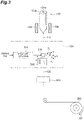
- Fig. 3 is a diagram illustrating an example of an optical fiber manufacturing device (drawing device) for implementing the optical fiber manufacturing method according to the embodiment of the present disclosure.
- the optical fiber manufacturing device illustrated Fig. 3 includes a heater 150 for heating one end of an optical fiber preform 100, a drum 200 for winding a coated fiber 120 obtained as a result of coating, with resin, a bared fiber (glass fiber) 110 obtained as a result of drawing the optical fiber preform 100, a resin coating device 300, and a coating condition detection device 500.
- the optical fiber preform 100 includes a core portion 100a and a cladding portion 100b.
- the core portion 100a is a region to be a core 110a of the bared fiber 110 obtained as a result of drawing the preform
- the cladding portion 100b is a region that surrounds the core portion 100a and is to be a cladding 110b of the bared fiber 110.
- the resin coating device 300 includes a die 310 for coating the outer peripheral surface of the bared fiber 110 with an ultraviolet-curable resin, a posture control device 320 for adjusting the posture of the die 310, and an ultraviolet irradiation device 330.
- the coating condition detection device 500 detects a two-dimensional grayscale image showing the cross section of the coated fiber 120 using ultraviolet rays emitted from the ultraviolet irradiation device 330 of the resin coating device 300 located on the upstream side of the coating condition detection device 500.
- a cooling device for forcibly cooling the bared fiber 110 is disposed between the optical fiber preform 100 and the resin coating device 300.
- Fig. 3 illustrates an example where the single-stage resin coating device 300 is provided, a plurality of stages of resin coating devices may be arranged in a longitudinal direction of the coated fiber 120 to be wound around the drum. Further, the resin used in the resin coating device 300 need not necessarily be the ultraviolet-curable resin.
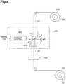
- Fig. 4 is a diagram illustrating an example applied to a resin coating device configured to further coat, with resin (for example, colored resin), the outer peripheral surface of the coated fiber obtained after the preform is drawn.
- the example illustrated in Fig. 4 is a device that rewinds a coated fiber 120 from the drum (drum around which the coated fiber 120 manufactured by the optical fiber manufacturing device illustrated in Fig. 3 is wound) 200 around a drum 210 while coloring the coated fiber.
- a resin coating device 400 coats, with the colored resin, the outer peripheral surface of the coated fiber 120 to be rewound around the drum 210 rotating in a direction indicated by an arrow S3 from the drum 200 rotating in a direction indicated by an arrow S2.
- the coating condition detection device of the present disclosure is disposed on the downstream side of the resin coating device 400.
- the resin coating device 400 illustrated in Fig. 4 is the same in structure as the resin coating device 300 illustrated in Fig. 3 , and a colored coated fiber 130 is obtained as a result of coating the coated fiber 120 with the colored resin by the resin coating device 400. That is, the resin coating device 400 includes a die 410 for coating the outer peripheral surface of the coated fiber 120 with an ultraviolet-curable resin (colored resin), a posture control device 420 for adjusting the posture of the die 410, and an ultraviolet irradiation device 430. Further, the coating condition detection device 500 illustrated in Fig. 4 also detects a two-dimensional grayscale image showing the cross section of the colored coated fiber 130 using ultraviolet rays emitted from the ultraviolet irradiation device 430 of the resin coating device 400 located on the upstream side of the coating condition detection device 500.
- the coating condition detection device 500 illustrated in Fig. 4 also detects a two-dimensional grayscale image showing the cross section of the colored coated fiber 130 using ultraviolet rays emitted from the ultraviolet irradiation device 430
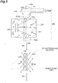
- Fig. 5 is a diagram for describing a mechanism of allowing the coating condition detection device 500 of the present disclosure to work on the downstream side of the resin coating device 300 or on the downstream side of the resin coating device 400, that is, a mechanism of how light is released from the coated fiber as illustrated in Figs. 3 and 4 .
- Fig. 5 illustrates an internal structure of the resin coating device 300 of the optical fiber manufacturing device illustrated in Fig. 3
- the resin coating device 400 illustrated in Fig. 4 also allows the coated fiber to release ultraviolet rays by the same mechanism.
- the bared fiber 110 obtained after the preform is drawn includes core 110a and cladding 110b provided on the outer peripheral surface of the core 110a.
- the bared fiber 110 moves in a direction indicated by an arrow S4 (in Fig. 3 , a direction from the optical fiber preform 100 toward the drum 200)
- the bared fiber 110 passes through the resin coating device 300.
- the bared fiber 110 that has entered the resin coating device 300 passes through the die 310 into which the resin (ultraviolet-curable resin) is introduced so as to have its outer peripheral surface coated with resin 110c.
- the bared fiber 110 having the resin 110c passes through the ultraviolet irradiation device 330.
- the ultraviolet irradiation device 330 includes a housing 331 in which an ultraviolet light source 333 is disposed.
- the housing 331 has an input-side opening 332a and an output-side opening 332b provided for introducing the bared fiber 110 having the resin 110c.
- the bared fiber 110 having the resin 110c is irradiated with ultraviolet rays UV outputted from the ultraviolet light source 333 while moving from the input-side opening 332a to the output-side opening 332b.
- the ultraviolet rays UV are partially reflected off the bared fiber 110 having the resin 110c, but partially enter the bared fiber 110 and propagate in any direction (scattered light) in the bared fiber 110 having the resin 110c.
- the coated fiber 120 is obtained as a result of irradiating the resin 110c with the ultraviolet rays UV.
- Fig. 5 illustrates a positional relation between a portion from which the ultraviolet rays UV are released, and the object plane OP and the reflection plane (the flat reflection mirror 20, the ellipsoid mirror 50, and off-axis parabolic mirror 60).
- the coating condition detection device 500 can detect, via the reflection plane, light (the ultraviolet rays UV in the example illustrated in Fig. 5 ) released from the portion of the coated fiber 120 that has passed through the reflection plane, the portion intersecting the object plane OP.
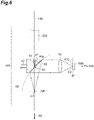
- Fig. 6 is a diagram illustrating a specific example where a coating condition detector (the coating condition detection device 500 of the present disclosure) to which the imaging optical system 2B illustrated in Fig. 2 is applied is applied to the optical fiber manufacturing device illustrated in Fig. 3 . Note that an imaging optical system other than the imaging optical system 2B illustrated in Fig. 2 may be applied.
- a coating condition detector the coating condition detection device 500 of the present disclosure
- the configuration where the coating condition detection device 500 of the present disclosure is disposed on the downstream side of the resin coating device 300 (or the resin coating device 400) eliminates the need of preparing an external light source, but a configuration where the resin coating device 300 located on the upstream side and the coating condition detection device 500 located on the downstream side are at a distance from each other may be unable to detect a sufficient amount of released light.
- an external light source 350 that emits light having a wavelength that can pass through the coated fiber 120 may be provided near the guide member 40 having the off-axis parabolic mirror 60 provided on one side of the guide member 40.
- the off-axis parabolic mirror 60 is provided on the one side of guide member 40, and the guide member 40 is provided with the guide hole 40a that connects the output-side opening 61 provided in the off-axis parabolic mirror 60 and the input-side opening 41.
- the coated fiber 120 having the resin 110c is wound around the drum 200 after passing through the guide hole 40a in a direction indicated by an arrow S5.
- the support member 42 fixes the position of the guide member 40 relative to the coated fiber 120 so as to cause the coated fiber 120 that has passed through the guide hole 40a to pass through the focal point of the off-axis parabolic mirror 60.
- the off-axis parabolic mirror 60 coincides with a part of the paraboloid of revolution 62, so that the focal point of the off-axis parabolic mirror 60 is located on the object plane OP. Further, this focal point becomes the conjugate point C1 conjugate with the intersection C2 of the optical axis AX and the imaging plane IP (which coincides with a light receiving surface 610 of a light receiving device 600 on the optical axis AX).
- "coincides with the light receiving surface” does not necessarily mean an exact coincidence, and a slight difference of about 0.1 ⁇ m is allowed.
- the collimated reflected light travels from the off-axis parabolic mirror 60 toward the collimator lens 12, and is concentrated by the collimator lens 12 onto the conjugate point C2 on the imaging plane IP.
- the coating condition detection device 500 includes a controller 700, and the controller 700 controls a rendering unit 720 in order to output, onto a monitor, a two-dimensional image visually representing the coating condition of the resin 110c of the coated fiber 120 on the basis of intensity of light detected by the light receiving device 600 and information on a corresponding position (see Fig. 7 ).
- the rendering unit 720 generates, from the grayscale image showing the cross section of the coated fiber 120 that is a detection target, a monitor screen 810 representing two-dimensionally a light intensity distribution shown on each of two orthogonal axes Ix, Iy on the imaging plane IP, the orthogonal axes Ix, Iy being orthogonal to each other at the intersection of the axis on the imaging plane IP corresponding to the fiber axis and the imaging plane IP.
- the rendering unit 720 can also generate a monitor screen 820 representing two-dimensionally a light intensity distribution in a circumferential direction around the axis on the imaging plane IP corresponding to the fiber axis, and generates at least one of the monitor screens 810, 820.
- the controller 700 can perform various types of control in addition to rendering control (generation of the two-dimensional image visually representing the coating condition of the resin 110c of the coated fiber 120) on the rendering unit 720. For example, performing numerical analyses on an image once captured by an image capturing device such as a camera allows the coating condition of the resin 110c to be quantitatively or dynamically determined.
- a detectable coating condition of the resin 110c include a degree of unevenness in thickness of the resin (resin layer) 110c (a degree of eccentricity of the bared fiber 110 in the coated fiber 120), a degree of mixture of air bubbles in the resin 110c, a degree of separation along the interface between the bared fiber 110 and the resin 110c, and the like.
- control signal (control information) 710 used for controlling the operation of each unit of the manufacturing device or the like on the basis of the detection data thus given to change the resin coating condition.
- the controller 700 outputs the control signal 710 to the posture control device 320 (or the posture control device 420 illustrated in Fig. 4 ) to change the posture of the die 310 illustrated in Fig. 3 and the like.
- the posture control performed by the controller 700 on the resin coating device 300 includes (1) moving the die 310 along a plane orthogonal to the travel direction of the coated fiber 120 (an x-y plane defined by the x axis and the y axis orthogonal to each other), (2) tilting the die 310 in a direction indicated by an arrow ⁇ x about the x axis, (3) tilting the die 310 in a direction indicated by an arrow ⁇ y about the y axis, and the like. Note that such a posture control is performed on the resin coating device 400 illustrated in Fig. 4 in the same manner.
- the controller 700 can further regulate a flow rate of a flushing gas (for example, CO 2 gas) applied to an inlet for the bared fiber provided in the resin coating device 300 to prevent air bubbles from mixing into the resin 110c.
- a flushing gas for example, CO 2 gas
- the controller 700 can further output the control signal 710 used for changing a temperature to the cooling device disposed on the upstream side of the resin coating device 300 to prevent air bubbles from mixing into the resin 110c.
Landscapes
- Chemical & Material Sciences (AREA)
- Life Sciences & Earth Sciences (AREA)
- Materials Engineering (AREA)
- General Life Sciences & Earth Sciences (AREA)
- Organic Chemistry (AREA)
- Geochemistry & Mineralogy (AREA)
- General Chemical & Material Sciences (AREA)
- Chemical Kinetics & Catalysis (AREA)
- Engineering & Computer Science (AREA)
- Physics & Mathematics (AREA)
- General Physics & Mathematics (AREA)
- Analytical Chemistry (AREA)
- Pathology (AREA)
- Immunology (AREA)
- General Health & Medical Sciences (AREA)
- Biochemistry (AREA)
- Health & Medical Sciences (AREA)
- Optics & Photonics (AREA)
- Optical Fibers, Optical Fiber Cores, And Optical Fiber Bundles (AREA)
- Surface Treatment Of Glass Fibres Or Filaments (AREA)
- Investigating Materials By The Use Of Optical Means Adapted For Particular Applications (AREA)
- Testing Of Optical Devices Or Fibers (AREA)
Abstract
Description
- The present disclosure relates to a coating condition detection method, a coating condition detection device, and an optical fiber manufacturing method.
- This application claims the priority of
Japanese Patent Application No. 2020-013921 filed on January 30, 2020 - As a method for measuring a degree of eccentricity of a coated fiber obtained as a result of coating a glass fiber (bared fiber) with resin during preform drawing,
Patent Documents 1 to 4 disclose an optical fiber eccentricity measurement device and measurement method for causing a laser light source to emit a laser beam to a side surface of the coated fiber to detect a grayscale image formed by forward scattered light (transmitted light) of the laser beam, and measuring a degree of eccentricity of the glass fiber in the coated fiber on the basis of a degree of unevenness in thickness of a resin layer. -
- Patent Document 1:
Japanese Patent Application Laid-Open No. H4-315939 - Patent Document 2:
Japanese Patent Application Laid-Open No. H4-319642 - Patent Document 3:
Japanese Patent Application Laid-Open No. H5-107046 - Patent Document 4:
Japanese Patent Application Laid-Open No. H5-087681 - A coating condition detection method according to an embodiment of the present disclosure is a method for detecting a coating condition of resin with which an optical fiber is coated (coated fiber) in a circumferential direction around a fiber axis using light released from the optical fiber. Under the coating condition detection method according to one aspect, an imaging optical system is prepared, and intensity of light at each point of an image formed by imaging optical system on an imaging plane (light receiving surface) is detected with the intensity of light associated with information on a corresponding position on an object plane. Specifically, the imaging optical system thus prepared includes a reflection mirror disposed on an optical path between the imaging plane and the object plane conjugate with the imaging plane. The reflection mirror has a guide hole through which the coated fiber passes. Further, on the imaging plane side, the imaging optical system is caused to form, on the imaging plane, an image of light released from a portion of the coated fiber that has passed through the guide hole of the reflection mirror, the portion intersecting the object plane, to detect intensity of light at each position on the imaging plane with the intensity of light associated with information on a corresponding position on the object plane.
-
-
Fig. 1 is a diagram illustrating various examples of an imaging optical system applicable to a coating condition detection device according to an embodiment of the present disclosure, the imaging optical system including a reflection mirror having a flat surface. -
Fig. 2 is a diagram illustrating various examples of an imaging optical system applicable to the coating condition detection device according to the embodiment of the present disclosure, the imaging optical system including a reflection mirror having a curved surface. -
Fig. 3 is a diagram illustrating an example of an optical fiber manufacturing device (drawing device) for implementing an optical fiber manufacturing method according to the embodiment of the present disclosure. -
Fig. 4 is a diagram illustrating an example applied to a resin coating device configured to further coat, with resin, an outer peripheral surface of a coated fiber obtained after a preform is drawn. -
Fig. 5 is a diagram for describing a mechanism of how light is released from a drawn optical fiber. -
Fig. 6 is a diagram illustrating an example where a coating condition detector to which an imagingoptical system 2B illustrated inFig. 2 is applied is applied to the optical fiber manufacturing device illustrated inFig. 3 . -
Fig. 7 is a diagram for describing an example of control operation of a controller (data processor) of a coating condition detection device according to the embodiment of the present disclosure. - As a result of examining the above-described conventional techniques, the inventors have found the following problems. That is, when a ratio between a coating outer diameter (an outer diameter of the coated fiber) and a glass diameter (an outer diameter of the bared fiber) is small (for example, 1.7 or less), the grayscale image formed by monitor light for detecting a degree of unevenness in thickness of the coated resin layer cannot be visually recognized or is hardly visually recognized. Further, in order to detect the degree of unevenness in thickness of the resin layer in the circumferential direction around the fiber axis from the side surface of the coated fiber, it is necessary to prepare a plurality of detection optical systems (a laser light source and a light receiving device), which makes the alignment work of the detection optical systems complicated, makes the device larger in size, and makes the device structure complicated, in addition to an increase in cost of manufacturing the device.
- The present disclosure has been made to solve the above-described problems, and it is therefore an object of the present disclosure to provide a coating condition detection method, a coating condition detection device, and an optical fiber manufacturing method that allow, even when a ratio between a coating outer diameter and a glass diameter is small, a coating condition of a resin layer of a coated fiber to be detected with a simple device structure as compared with the related art.
- The coating condition detection method and the like of the present disclosure allow, when the ratio of the coating outer diameter to the glass diameter is small, the coating condition of the resin layer of the coated fiber to be detected with a simple device structure as compared with the related art.
- First, details of the embodiment of the present disclosure will be individually listed and described.
- (1) A coating condition detection method according to the embodiment of the present disclosure is a method for detecting a coating condition of resin with which an optical fiber is coated (coated fiber obtained as a result of coating a bared fiber with resin) in a circumferential direction around a fiber axis using light released from the coated fiber. Under the coating condition detection method according to one aspect, an imaging optical system is prepared, and intensity of light at each point of an image formed by imaging optical system on an imaging plane (light receiving surface) is detected with the intensity of light associated with information on a corresponding position on an object plane. Specifically, the imaging optical system thus prepared includes a reflection mirror disposed on an optical path between the imaging plane and the object plane conjugate with the imaging plane. The reflection mirror has a guide hole through which the coated fiber passes. Further, on the imaging plane side, the imaging optical system is caused to form, on the imaging plane, an image of light released from a portion of the coated fiber that has passed through the guide hole of the reflection mirror, the portion intersecting the object plane, to detect intensity of light at each position on the imaging plane with the intensity of light associated with information on a corresponding position on the object plane.
- Note that the "light released from the coated fiber" is a light component released to the outside of the optical fiber after propagating in the optical fiber among light components emitted to the optical fiber during manufacturing, and examples of such a light component include UV light for curing the coating of the optical fiber.
- Note that the imaging optical system may be configured to form an intermediate imaging plane on the optical path between the object plane and the imaging plane. Such a configuration allows an increase in contrast of a grayscale image formed on the imaging plane by disposing a diaphragm on the intermediate imaging plane.
- The above-described configuration allows the coating condition of the resin layer around the fiber axis to be efficiently detected with a simple device structure. In other words, the above-described configuration allows the coating condition in the circumferential direction around the fiber axis to be detected without depending on a ratio between a coating outer diameter (an outer diameter of the coated fiber) and a glass diameter (an outer diameter of the bared fiber). Note that, the "coating condition of the resin" refers herein to fluctuations in thickness in the circumferential direction of the resin layer provided on the outer periphery of the bared fiber (a degree of unevenness in thickness of the resin layer or a degree of eccentricity of the bared fiber in the coated fiber), a degree of mixture of air bubbles in the resin layer, and a degree of separation along the interface between the bared fiber and the resin layer, and the like. Further, the coated fiber that is a detection target is a coated fiber obtained as a result of coating a glass fiber (bared fiber) with a resin layer, and the resin layer includes a single layer (primary coating) or a plurality of layers (continuous layers of the primary coating, the secondary coating, and the like) provided on the bared fiber during preform drawing. The resin layer also includes colored resin with which the coated fiber is coated while the coated fiber wound around the drum during preform drawing is rewound around another drum.
- (2) According to one aspect of the present disclosure, a two-dimensional image visually representing the coating condition of the resin on the basis of the intensity of light detected and the information on the corresponding position may be outputted onto a monitor. This allows the condition of the cross section of the coated fiber that is a detection target to be visually confirmed.
- (3) According to one aspect of the present disclosure, the two-dimensional image may include at least one of a grayscale image showing a cross section of the coated fiber that is a detection target, a light intensity distribution shown along each of two orthogonal axes on the imaging plane, the two orthogonal axes being orthogonal to each other at an intersection of an axis on the imaging plane corresponding to the fiber axis and the imaging plane, or a light intensity distribution in a circumferential direction around the axis on the imaging plane corresponding to the fiber axis. In particular, performing numerical analyses on an image once captured by an image capturing device such as a camera allows the coating condition (fluctuations in thickness in the circumferential direction of the resin layer, a degree of mixture of air bubbles in the resin layer, or a degree of separation along the interface between the bared fiber and the resin layer) to be quantitatively or dynamically determined. Further, giving detection data to a measuring instrument enables a process control (it is possible to generate control information used for controlling the operation of each unit of a manufacturing device or the like on the basis of the detection data thus given).
- (4) According to one aspect of the present disclosure, the reflection mirror may include an off-axis parabolic mirror, and in this case, the off-axis parabolic mirror has a hole serving as the guide hole. When the off-axis parabolic mirror is used as the reflection mirror, the imaging optical system is disposed so as to cause the coated fiber to pass through a focal point of the off-axis parabolic mirror after passing through the hole of the off-axis parabolic mirror. The off-axis parabolic mirror reflects light from the focal point as collimated light. Therefore, the use of the off-axis parabolic mirror as the reflection mirror allows a reduction in the number of lens elements constituting the imaging optical system (simplification of the structure of the imaging optical system).
- (5) According to one aspect of the present disclosure, the reflection mirror may include an ellipsoid mirror, and in this case, the ellipsoid mirror has a hole serving as the guide hole. When the ellipsoid mirror is used as the reflection mirror, the imaging optical system is disposed so as to cause the coated fiber to pass through one focal point of the ellipsoid mirror after passing through the hole of the ellipsoid mirror and to cause an other focal point of the ellipsoid mirror to be positioned on the imaging plane or an optical path between the ellipsoid mirror and the imaging plane. The ellipsoid mirror concentrates light from the one focal point on the other focal point (the two focal points are conjugate with each other). Therefore, the use of the ellipsoid mirror as the reflection mirror allows the imaging optical system to be constituted of only the ellipsoid mirror. Further, even a combination of the ellipsoid mirror and a lens can constitute an imaging optical system having a simple structure (simplification of the structure of the imaging optical system).
- (6) According to one aspect of the present disclosure, the light released from the coated fiber may include resin curing light emitted to the resin in a space on a side of the reflection mirror remote from the object plane. That is, when the coating condition detection method is applied to a coated fiber manufacturing device (drawing device), disposing the above-described imaging optical system on the downstream side of a resin coating device allows a light source for resin curing to be used as a light source for coating condition detection.
- (7) According to one aspect of the present disclosure, the light released from the optical fiber may include light from an external light source other than the resin curing light emitted to the optical fiber in the space on the side of the reflection mirror remote from the object plane. As described above, preparing the external light source separately from an ultraviolet light source of the resin coating device increases the degree of freedom in arrangement of the imaging optical system. Further, installing the external light source can make the grayscale image formed by the light released from the coating of the coated fiber clearer (increase the S/N ratio of the grayscale image formed on the imaging plane).
- (8) A coating condition detection device according to the embodiment of the present disclosure is a device for implementing the above-described coating condition detection method, and the coating condition detection device is structured to detect the coating condition of resin with which an optical fiber is coated (coated fiber) in the circumferential direction around a fiber axis using light released from the coated fiber. Specifically, according to one aspect, the coating condition detection device includes a light receiving device and an imaging optical system. The imaging optical system includes a reflection mirror disposed on an optical path between an imaging plane to be projected onto a light receiving surface of the light receiving device and an object plane conjugate with the imaging plane. The reflection mirror having a guide hole through which the coated fiber passes. Further, the light receiving device detects intensity of light at each point on the imaging plane where an image of the light released from a portion of the coated fiber that has passed through the guide hole of the reflection mirror is formed by the imaging optical system, the portion intersecting the object plane, with the intensity of light associated with information on a corresponding position on the object plane. This configuration allows the above-described coating condition detection method to be implemented.
- (9) According to one aspect of the present disclosure, the coating condition detection device may further include a controller configured to output, onto a monitor, a two-dimensional image visually representing the coating condition of the resin on the basis of the intensity of light detected by the light receiving device and the information on the corresponding position. This allows the condition of the cross section of the coated fiber that is a detection target to be visually confirmed. Further, the two-dimensional image may include at least one of a grayscale image corresponding to the cross section of the coated fiber that is a detection target, a light intensity distribution shown along each of two orthogonal axes on the imaging plane, the two orthogonal axes being orthogonal to each other at an intersection of the fiber axis and the imaging plane, or a light intensity distribution in the circumferential direction around the fiber axis. For example, performing numerical analyses on an image once captured by an image capturing device such as a camera allows the coating condition (fluctuations in thickness in the circumferential direction of the resin layer, a degree of mixture of air bubbles in the resin layer, or a degree of separation along the interface between the bared fiber and the resin layer) to be quantitatively or dynamically determined. Further, giving detection data to a measuring instrument enables a process control (it is possible to generate control information used for controlling the operation of each unit of a manufacturing device or the like on the basis of the detection data thus given).
- (10) According to one aspect of the present disclosure, the reflection mirror may include an off-axis parabolic mirror, and in this case, the off-axis parabolic mirror has a hole serving as the guide hole. When the off-axis parabolic mirror is used as the reflection mirror, the imaging optical system is disposed so as to cause the coated fiber to pass through a focal point of the off-axis parabolic mirror after passing through the hole of the off-axis parabolic mirror. This can make the imaging optical system simple in structure as described above.
- (11) According to one aspect of the present disclosure, the reflection mirror may include an ellipsoid mirror, and in this case, the ellipsoid mirror has a hole serving as the guide hole. When the ellipsoid mirror is used as the reflection mirror, the imaging optical system is disposed so as to cause the coated fiber to pass through one focal point of the ellipsoid mirror after passing through the hole of the ellipsoid mirror and to cause an other focal point of the ellipsoid mirror to be positioned on the imaging plane or an optical path between the ellipsoid mirror and the imaging plane. This can also make the imaging optical system simple in structure as described above.
- (12) According to one aspect of the present disclosure, the coating condition detection device may include, in a space on a side of the reflection mirror remote from the object plane, a light source configured to emit, to the optical fiber including the resin, light that can propagate in the optical fiber. When the coating condition detection device is applied to the optical fiber manufacturing device, disposing the coating condition detection device on the downstream side of the resin coating device allows light from the ultraviolet light source of the resin coating device to be used as detection light (released light), for example. Further, the use of an external light source in addition to the light source (the ultraviolet light source for resin curing) of the resin coating device can effectively increase the S/N ratio of the grayscale image formed on the imaging plane.
- (13) An optical fiber manufacturing method according to the embodiment of the present disclosure is a method for winding a bared fiber with the bared fiber coated with resin, the bared fiber being obtained as a result of drawing an optical fiber preform. In particular, under the optical fiber manufacturing method according to one aspect, a coating condition detection device having the above-described structure (the coating condition detection device of the present disclosure) is disposed on the downstream side of a resin coating device including a die configured to coat the bared fiber with the resin, and a resin coating condition is changed on the basis of a detection result obtained from the coating condition detection device. Note that examples of the resin coating condition include regulation of a flow rate of a flushing gas (CO2 regulation), prevention of air bubbles from mixing into the resin layer (specifically, temperature control on a cooling device disposed on the upstream side of the resin coating device), and the like, in addition to a change in posture of the die (elimination of eccentricity of the bared fiber in the coated fiber).
- As described above, each of the aspects listed in "Description of embodiment of present disclosure" is applicable to all remaining aspects or all combinations of the remaining aspects.
- Specific examples of an optical fiber coating condition detection method, an optical fiber coating condition detection device, and an optical fiber manufacturing method according to the present disclosure will be described in detail below with reference to the accompanying drawings. It should be noted that the present disclosure is not limited to such examples, and is intended to be defined by the claims and to include all modifications within the scope of the claims and their equivalents. Further, in a description of the drawings, the same components are denoted by the same reference numerals, and a redundant description will be omitted.
- First, a representative structure of an imaging optical system for implementing a coating condition detection method according to the embodiment of the present disclosure and a coating condition detection device according to the embodiment of the present disclosure (a device for implementing the coating condition detection method according to the embodiment of the present disclosure) will be described with reference to
Figs. 1 and2 . Note thatFig. 1 is a diagram illustrating various examples of an imaging optical system applicable to the coating condition detection method and the coating condition detection device according to the embodiment of the present disclosure, the imaging optical system including a reflection mirror having a flat surface. Note thatFig. 2 is a diagram illustrating various examples of an imaging optical system applicable to the coating condition detection method and the coating condition detection device according to the embodiment of the present disclosure, the imaging optical system including a reflection mirror having a curved surface. - An imaging
optical system 1A illustrated inFig. 1 is an imaging optical system having the simplest structure using a flat reflection mirror, and includes animaging lens 10 and aflat reflection mirror 20. A light receiving surface of a light receiving device that receives part of light released from a coated fiber is installed at an imaging plane IP, and an object plane OP and the imaging plane IP are conjugate with each other via theimaging lens 10. That is, an intersection C1 of an optical axis AX of the imagingoptical system 1A and the object plane OP and an intersection C2 of the optical axis AX and the imaging plane IP are conjugate points. Theflat reflection mirror 20 is disposed on an optical path between the object plane OP and theimaging lens 10, and light released from the object plane OP is reflected off theflat reflection mirror 20 and concentrated onto the imaging plane IP. Further, theflat reflection mirror 20 is provided on one side of aguide member 30. Furthermore, theflat reflection mirror 20 and theguide member 30 have aguide hole 30a through which the coated fiber passes, and theflat reflection mirror 20 has an output-side opening 21 of theguide hole 30a. The coated fiber passes through from an input-side opening 31 of theguide hole 30a to the output-side opening 21 provided in theflat reflection mirror 20. Further, theguide member 30 is held by asupport member 32 in order to fix a positional relationship between the coated fiber and theflat reflection mirror 20. - For example, when the imaging
optical system 1A is disposed so as to cause the coated fiber that has passed through theguide hole 30a of theguide member 30 connecting the input-side opening 31 and the output-side opening 21 to intersect the object plane OP at the conjugate point C1, the imaging plane IP is formed at a distance from the coated fiber by a predetermined distance, and light released from a portion of the coated fiber located at the conjugate point C1 forms an image at the conjugate point C2 on the imaging plane IP. As a result, a two-dimensional grayscale image showing the cross section of the coated fiber at the conjugate point C1 is formed on the imaging plane IP. - An imaging
optical system 1B illustrated inFig. 1 includes twocollimator lenses flat reflection mirror 20. Further, it is possible to adjust a length (optical path length) of an optical axis AX of the imagingoptical system 1B by changing a distance L between thecollimator lenses collimator lens 11, and the position of the imaging plane IP is determined by a position of a focal point of thecollimator lens 12. The object plane OP and the imaging plane IP are conjugate with each other via thecollimator lenses optical system 1B and the object plane OP and the intersection C2 of the optical axis AX and the imaging plane IP are conjugate points. Theflat reflection mirror 20 is disposed on the optical path between the object plane OP and thecollimator lens 11, and light released from the object plane OP is reflected off the flat reflection mirror and concentrated onto the imaging plane IP. Further, as with the imagingoptical system 1A, theflat reflection mirror 20 is provided on one side of theguide member 30 whose position relative to the coated fiber is fixed by thesupport member 32. Theguide member 30 is provided with theguide hole 30a that connects the output-side opening 21 and the input-side opening 31 provided in theflat reflection mirror 20. - Also in the imaging
optical system 1B, when the imagingoptical system 1B is disposed so as to cause the coated fiber that has passed through theguide hole 30a of theguide member 30 connecting the input-side opening 31 and the output-side opening 21 to intersect the object plane OP at the conjugate point C1, light released from a portion of the coated fiber located at the conjugate point C1 forms an image at the conjugate point C2 on the imaging plane IP. As a result, a two-dimensional grayscale image showing the cross section of the coated fiber at the conjugate point C1 is formed on the imaging plane IP. - An imaging
optical system 1C illustrated inFig. 1 includes twoimaging lenses flat reflection mirror 20, and adiaphragm 15 disposed between the twoimaging lenses optical system 1C, thediaphragm 15 is disposed on an imaging plane formed on an optical path between theimaging lens 13 and theimaging lens 14, and the object plane OP, the plane on which thediaphragm 15 is disposed, and the imaging plane IP are conjugate with each other. That is, the intersection C1 of the optical axis AX of the imagingoptical system 1C and the object plane OP, and the intersection C2 of the optical axis AX and the imaging plane IP are conjugate points. The C2 and an intersection C3 of the optical axis AX and the imaging plane on which thediaphragm 15 is disposed are conjugate points. Theflat reflection mirror 20 is disposed on an optical path between the object plane OP and theimaging lens 13, and light released from the object plane OP is reflected off theflat reflection mirror 20 and concentrated onto the imaging plane IP. Further, as with the imagingoptical system 1A, theflat reflection mirror 20 is provided on one side of theguide member 30 whose position relative to the coated fiber is fixed by thesupport member 32. Theguide member 30 is provided with theguide hole 30a that connects the output-side opening 21 and the input-side opening 31 provided in theflat reflection mirror 20. - Also in the imaging
optical system 1C, when the imagingoptical system 1C is disposed so as to cause the coated fiber that has passed through theguide hole 30a of theguide member 30 connecting the input-side opening 31 and the output-side opening 21 to intersect the object plane OP at the conjugate point C1, light released from a portion of the coated fiber located at the conjugate point C1 forms an image at the conjugate point C2 on the imaging plane IP. As a result, a two-dimensional grayscale image showing the cross section of the coated fiber at the conjugate point C1 is formed on the imaging plane IP. Note that when the coated fiber that has passed through theflat reflection mirror 20 intersects the object plane OP at a position that is not coincident with the conjugate point C1, the position of thediaphragm 15 on the imaging plane (plane orthogonal to the optical axis AX) is adjusted. - The imaging
optical system 1A to the imagingoptical system 1C described above are each an imaging optical system including theflat reflection mirror 20, but the use of a special curved mirror instead of theflat reflection mirror 20 can make the imaging optical system simpler in structure. For example, an imagingoptical system 2A illustrated inFig. 2 is obtained as a result of applying a reflection mirror (hereinafter, referred to as an "ellipsoid mirror") 50 having a curved surface coincident with a part of aspheroid surface 52 to the imagingoptical system 1A illustrated inFig. 1 or the imagingoptical system 1C illustrated inFig. 1 . Further, an imagingoptical system 2B illustrated inFig. 2 is obtained as a result of applying an off-axisparabolic mirror 60 having a curved surface coincident with a part of a paraboloid ofrevolution 62 to the imagingoptical system 1B illustrated inFig. 1 . - Specifically, in the imaging
optical system 2A to which theellipsoid mirror 50 is applied instead of theflat reflection mirror 20 and theimaging lens 10 of the imagingoptical system 1A illustrated inFig. 1 , the position of the object plane OP is determined by the position of one of the two focal points of the ellipsoid mirror 50 (two focal points of the spheroid), and the position of the imaging plane IP is determined by the position of the other focal point (the two focal points of theellipsoid mirror 50 are conjugate points C1, C2). This allows the imagingoptical system 2A to work in the same manner as the imagingoptical system 1A even without a lens element on the optical axis AX. - Further, in the imaging
optical system 2A to which theellipsoid mirror 50 is applied instead of theflat reflection mirror 20 and theimaging lens 13 of the imagingoptical system 1C illustrated inFig. 1 , the position of the object plane OP is determined by the position of one of the two focal points of theellipsoid mirror 50, and the position of the other focal point coincides with the position of the imaging plane on which thediaphragm 15 is disposed (two focal points of theellipsoid mirror 50 are conjugate points C1, C3). This allows the imagingoptical system 2A to work in the same manner as the imagingoptical system 1C with the number of lenses arranged on the optical axis AX reduced. - In the imaging
optical system 2A, light released from the object plane OP is reflected off theellipsoid mirror 50 and concentrated onto the imaging plane IP. Further, as with the imagingoptical system 1A and the imagingoptical system 1C, theellipsoid mirror 50 is provided on one side of aguide member 40 whose position relative to the coated fiber is fixed by asupport member 42. Theguide member 40 is provided with aguide hole 40a that connects an output-side opening 51 provided in theellipsoid mirror 50 and an input-side opening 41. - Further, in the imaging
optical system 2B to which the off-axisparabolic mirror 60 is applied instead of theflat reflection mirror 20 and thecollimator lens 11 of the imagingoptical system 1B illustrated inFig. 1 , the position of the object plane OP is determined by the position of the focal point of the off-axisparabolic mirror 60, and the position of the imaging plane IP is determined by the position of the focal point of thecollimator lens 12. In this case, the focal point of off-axisparabolic mirror 60 is conjugate with the intersection C2 of the optical axis AX and the imaging plane IP (the mirror focal point on the object plane OP is the conjugate point C1 conjugate with the intersection C2 on the imaging plane IP). Therefore, in the imagingoptical system 2B, light from the focal point of the off-axisparabolic mirror 60 is collimated by the off-axisparabolic mirror 60, and an image is formed on the imaging plane IP by thecollimator lens 12. - In the imaging
optical system 2B, light released from the object plane OP is reflected off the off-axisparabolic mirror 60 and concentrated onto the imaging plane IP. Further, as with the imagingoptical system 1A and the like, the off-axisparabolic mirror 60 is provided on one side of theguide member 40 whose position relative to the coated fiber is fixed by thesupport member 42. Theguide member 40 is provided with theguide hole 40a that connects an output-side opening 61 provided in the off-axisparabolic mirror 60 and the input-side opening 41. -
Fig. 3 is a diagram illustrating an example of an optical fiber manufacturing device (drawing device) for implementing the optical fiber manufacturing method according to the embodiment of the present disclosure. Specifically, the optical fiber manufacturing device illustratedFig. 3 includes aheater 150 for heating one end of anoptical fiber preform 100, adrum 200 for winding acoated fiber 120 obtained as a result of coating, with resin, a bared fiber (glass fiber) 110 obtained as a result of drawing theoptical fiber preform 100, aresin coating device 300, and a coatingcondition detection device 500. Theoptical fiber preform 100 includes acore portion 100a and acladding portion 100b. Note that thecore portion 100a is a region to be a core 110a of the baredfiber 110 obtained as a result of drawing the preform, and thecladding portion 100b is a region that surrounds thecore portion 100a and is to be acladding 110b of the baredfiber 110. When thedrum 200 rotates in a direction indicated by an arrow S1, thecoated fiber 120 is wound around thedrum 200. Theresin coating device 300 is a device that is disposed between theoptical fiber preform 100 and thedrum 200 and that coats the outer peripheral surface of the running baredfiber 110 with resin. The baredfiber 110 is coated with resin by theresin coating device 300 to become thecoated fiber 120. Theresin coating device 300 includes adie 310 for coating the outer peripheral surface of the baredfiber 110 with an ultraviolet-curable resin, aposture control device 320 for adjusting the posture of thedie 310, and anultraviolet irradiation device 330. The coatingcondition detection device 500 detects a two-dimensional grayscale image showing the cross section of thecoated fiber 120 using ultraviolet rays emitted from theultraviolet irradiation device 330 of theresin coating device 300 located on the upstream side of the coatingcondition detection device 500. - Note that, although not illustrated, a cooling device for forcibly cooling the bared
fiber 110 is disposed between theoptical fiber preform 100 and theresin coating device 300. AlthoughFig. 3 illustrates an example where the single-stageresin coating device 300 is provided, a plurality of stages of resin coating devices may be arranged in a longitudinal direction of thecoated fiber 120 to be wound around the drum. Further, the resin used in theresin coating device 300 need not necessarily be the ultraviolet-curable resin. -
Fig. 4 is a diagram illustrating an example applied to a resin coating device configured to further coat, with resin (for example, colored resin), the outer peripheral surface of the coated fiber obtained after the preform is drawn. The example illustrated inFig. 4 is a device that rewinds acoated fiber 120 from the drum (drum around which thecoated fiber 120 manufactured by the optical fiber manufacturing device illustrated inFig. 3 is wound) 200 around adrum 210 while coloring the coated fiber. Aresin coating device 400 coats, with the colored resin, the outer peripheral surface of thecoated fiber 120 to be rewound around thedrum 210 rotating in a direction indicated by an arrow S3 from thedrum 200 rotating in a direction indicated by an arrow S2. The coating condition detection device of the present disclosure is disposed on the downstream side of theresin coating device 400. - The
resin coating device 400 illustrated inFig. 4 is the same in structure as theresin coating device 300 illustrated inFig. 3 , and a coloredcoated fiber 130 is obtained as a result of coating thecoated fiber 120 with the colored resin by theresin coating device 400. That is, theresin coating device 400 includes adie 410 for coating the outer peripheral surface of thecoated fiber 120 with an ultraviolet-curable resin (colored resin), aposture control device 420 for adjusting the posture of thedie 410, and anultraviolet irradiation device 430. Further, the coatingcondition detection device 500 illustrated inFig. 4 also detects a two-dimensional grayscale image showing the cross section of the coloredcoated fiber 130 using ultraviolet rays emitted from theultraviolet irradiation device 430 of theresin coating device 400 located on the upstream side of the coatingcondition detection device 500. -
Fig. 5 is a diagram for describing a mechanism of allowing the coatingcondition detection device 500 of the present disclosure to work on the downstream side of theresin coating device 300 or on the downstream side of theresin coating device 400, that is, a mechanism of how light is released from the coated fiber as illustrated inFigs. 3 and4 . AlthoughFig. 5 illustrates an internal structure of theresin coating device 300 of the optical fiber manufacturing device illustrated inFig. 3 , theresin coating device 400 illustrated inFig. 4 also allows the coated fiber to release ultraviolet rays by the same mechanism. - The bared
fiber 110 obtained after the preform is drawn includescore 110a andcladding 110b provided on the outer peripheral surface of thecore 110a. When the baredfiber 110 moves in a direction indicated by an arrow S4 (inFig. 3 , a direction from theoptical fiber preform 100 toward the drum 200), the baredfiber 110 passes through theresin coating device 300. First, the baredfiber 110 that has entered theresin coating device 300 passes through thedie 310 into which the resin (ultraviolet-curable resin) is introduced so as to have its outer peripheral surface coated withresin 110c. Subsequently, the baredfiber 110 having theresin 110c passes through theultraviolet irradiation device 330. Theultraviolet irradiation device 330 includes ahousing 331 in which anultraviolet light source 333 is disposed. Thehousing 331 has an input-side opening 332a and an output-side opening 332b provided for introducing the baredfiber 110 having theresin 110c. The baredfiber 110 having theresin 110c is irradiated with ultraviolet rays UV outputted from the ultravioletlight source 333 while moving from the input-side opening 332a to the output-side opening 332b. Note that the ultraviolet rays UV are partially reflected off the baredfiber 110 having theresin 110c, but partially enter the baredfiber 110 and propagate in any direction (scattered light) in the baredfiber 110 having theresin 110c. As described above, thecoated fiber 120 is obtained as a result of irradiating theresin 110c with the ultraviolet rays UV. - The ultraviolet rays UV emitted in the
housing 331 are confined within the coated fiber 120 (after theresin 110c is cured) coming out from the output-side opening 332b of thehousing 331 in the direction indicated by the arrow S4. Therefore, the ultraviolet rays UV are released from the surface of thecoated fiber 120 that has moved to the downstream side of theresin coating device 300.Fig. 5 illustrates a positional relation between a portion from which the ultraviolet rays UV are released, and the object plane OP and the reflection plane (theflat reflection mirror 20, theellipsoid mirror 50, and off-axis parabolic mirror 60). - As described above, with a light source such as the ultraviolet rays UV having a wavelength that can pass through the
coated fiber 120 already installed on the upstream side of the coatingcondition detection device 500 of the present disclosure, the coatingcondition detection device 500 can detect, via the reflection plane, light (the ultraviolet rays UV in the example illustrated inFig. 5 ) released from the portion of thecoated fiber 120 that has passed through the reflection plane, the portion intersecting the object plane OP. -
Fig. 6 is a diagram illustrating a specific example where a coating condition detector (the coatingcondition detection device 500 of the present disclosure) to which the imagingoptical system 2B illustrated inFig. 2 is applied is applied to the optical fiber manufacturing device illustrated inFig. 3 . Note that an imaging optical system other than the imagingoptical system 2B illustrated inFig. 2 may be applied. - As described with reference to
Fig. 5 , the configuration where the coatingcondition detection device 500 of the present disclosure is disposed on the downstream side of the resin coating device 300 (or the resin coating device 400) eliminates the need of preparing an external light source, but a configuration where theresin coating device 300 located on the upstream side and the coatingcondition detection device 500 located on the downstream side are at a distance from each other may be unable to detect a sufficient amount of released light. In such a case, as illustrated inFig. 6 , an externallight source 350 that emits light having a wavelength that can pass through thecoated fiber 120 may be provided near theguide member 40 having the off-axisparabolic mirror 60 provided on one side of theguide member 40. - As illustrated in
Fig. 6 , the off-axisparabolic mirror 60 is provided on the one side ofguide member 40, and theguide member 40 is provided with theguide hole 40a that connects the output-side opening 61 provided in the off-axisparabolic mirror 60 and the input-side opening 41. Thecoated fiber 120 having theresin 110c is wound around thedrum 200 after passing through theguide hole 40a in a direction indicated by an arrow S5. Thesupport member 42 fixes the position of theguide member 40 relative to thecoated fiber 120 so as to cause thecoated fiber 120 that has passed through theguide hole 40a to pass through the focal point of the off-axisparabolic mirror 60. Note that the off-axisparabolic mirror 60 coincides with a part of the paraboloid ofrevolution 62, so that the focal point of the off-axisparabolic mirror 60 is located on the object plane OP. Further, this focal point becomes the conjugate point C1 conjugate with the intersection C2 of the optical axis AX and the imaging plane IP (which coincides with alight receiving surface 610 of alight receiving device 600 on the optical axis AX). Here, "coincides with the light receiving surface" does not necessarily mean an exact coincidence, and a slight difference of about 0.1 µm is allowed. - Light released from a portion of the
coated fiber 120 that has passed through the output-side opening 61 of the off-axisparabolic mirror 60 located near the focal point of the off-axis parabolic mirror 60 (the position where the object plane OP and thecoated fiber 120 intersect each other) is partially collimated by and reflected off the off-axisparabolic mirror 60. The collimated reflected light travels from the off-axisparabolic mirror 60 toward thecollimator lens 12, and is concentrated by thecollimator lens 12 onto the conjugate point C2 on the imaging plane IP. The coatingcondition detection device 500 includes acontroller 700, and thecontroller 700 controls arendering unit 720 in order to output, onto a monitor, a two-dimensional image visually representing the coating condition of theresin 110c of thecoated fiber 120 on the basis of intensity of light detected by thelight receiving device 600 and information on a corresponding position (seeFig. 7 ). - Specifically, as illustrated in
Fig. 7 , therendering unit 720 generates, from the grayscale image showing the cross section of thecoated fiber 120 that is a detection target, amonitor screen 810 representing two-dimensionally a light intensity distribution shown on each of two orthogonal axes Ix, Iy on the imaging plane IP, the orthogonal axes Ix, Iy being orthogonal to each other at the intersection of the axis on the imaging plane IP corresponding to the fiber axis and the imaging plane IP. Therendering unit 720 can also generate amonitor screen 820 representing two-dimensionally a light intensity distribution in a circumferential direction around the axis on the imaging plane IP corresponding to the fiber axis, and generates at least one of the monitor screens 810, 820. - The
controller 700 can perform various types of control in addition to rendering control (generation of the two-dimensional image visually representing the coating condition of theresin 110c of the coated fiber 120) on therendering unit 720. For example, performing numerical analyses on an image once captured by an image capturing device such as a camera allows the coating condition of theresin 110c to be quantitatively or dynamically determined. Note that examples of a detectable coating condition of theresin 110c include a degree of unevenness in thickness of the resin (resin layer) 110c (a degree of eccentricity of the baredfiber 110 in the coated fiber 120), a degree of mixture of air bubbles in theresin 110c, a degree of separation along the interface between the baredfiber 110 and theresin 110c, and the like. Further, giving detection data to a measuring instrument enables a process control. That is, it is possible to generate a control signal (control information) 710 used for controlling the operation of each unit of the manufacturing device or the like on the basis of the detection data thus given to change the resin coating condition. - Note that, in order to change the resin coating condition, for example, the
controller 700 outputs thecontrol signal 710 to the posture control device 320 (or theposture control device 420 illustrated inFig. 4 ) to change the posture of the die 310 illustrated inFig. 3 and the like. Specifically, the posture control performed by thecontroller 700 on theresin coating device 300 includes (1) moving thedie 310 along a plane orthogonal to the travel direction of the coated fiber 120 (an x-y plane defined by the x axis and the y axis orthogonal to each other), (2) tilting thedie 310 in a direction indicated by an arrow γx about the x axis, (3) tilting thedie 310 in a direction indicated by an arrow γy about the y axis, and the like. Note that such a posture control is performed on theresin coating device 400 illustrated inFig. 4 in the same manner. - In addition to the posture control, the
controller 700 can further regulate a flow rate of a flushing gas (for example, CO2 gas) applied to an inlet for the bared fiber provided in theresin coating device 300 to prevent air bubbles from mixing into theresin 110c. Thecontroller 700 can further output thecontrol signal 710 used for changing a temperature to the cooling device disposed on the upstream side of theresin coating device 300 to prevent air bubbles from mixing into theresin 110c. -
- 1A, 1B, 1C, 2A, 2B ... imaging optical system
- 10, 13, 14 ... imaging lens
- 11, 12 ... collimator lens
- 15 ... diaphragm
- 20 ... flat reflection mirror
- 21, 51, 61, 332b ... output-side opening
- 30, 40 ... guide member
- 30a, 40a ... guide hole
- 31, 41, 332a ... input-side opening
- 32, 42 ... support member
- 50 ... ellipsoid mirror
- 52 ... spheroid surface
- 60 ... off-axis parabolic mirror
- 62 ... paraboloid of revolution
- 100 ... optical fiber preform
- 100a ... core portion
- 100b ... cladding portion
- 110 ... bared fiber
- 110a ... core
- 110b ... cladding
- 110c ... resin
- 120 ... coated fiber
- 130 ... colored coated fiber
- 150 ... heater
- 200, 210 ... drum
- 300, 400 ... resin coating device
- 310, 410 ... die
- 320, 420 ... posture control device
- 330, 430 ... ultraviolet irradiation device
- 331 ... housing
- 333 ... ultraviolet light source
- 500 ... coating condition detection device
- 600 ... light receiving device
- 610 ... light receiving surface
- 700 ... controller
- 710 ... control signal
- 720 ... rendering unit
- 810, 820 ... monitor screen
- OP ... object plane
- IP ... imaging plane
- AX ... optical axis
- UV ... ultraviolet ray
- C1, C2, C3 ... conjugate point
- S1, S2, S3, S4, S5 ... arrow (direction)
Claims (13)
- A coating condition detection method for detecting a coating condition of resin with which an optical fiber is coated in a circumferential direction around a fiber axis using light released from the optical fiber, the coating condition detection method comprising:preparing an imaging optical system including a reflection mirror disposed on an optical path between an imaging plane and an object plane conjugate with the imaging plane, the reflection mirror having a guide hole through which the optical fiber passes; andcausing the imaging optical system to form, on the imaging plane, an image of the light released from a portion of the optical fiber that has passed through the guide hole of the reflection mirror, the portion intersecting the object plane, to detect intensity of light at each point on the imaging plane with the intensity of light associated with information on a corresponding position on the object plane.
- The coating condition detection method according to claim 1,
wherein
a two-dimensional image visually representing the coating condition of the resin on the basis of the intensity of light detected and the information on the corresponding position is outputted onto a monitor. - The coating condition detection method according to claim 2,
wherein
the two-dimensional image includes at least one of a grayscale image showing a cross section of the optical fiber, a light intensity distribution shown along each of two orthogonal axes on the imaging plane, the two orthogonal axes being orthogonal to each other at an intersection of an axis on the imaging plane corresponding to the fiber axis and the imaging plane, or a light intensity distribution in a circumferential direction around the axis on the imaging plane corresponding to the fiber axis. - The coating condition detection method according to any one of claims 1 to 3, whereinthe reflection mirror includes an off-axis parabolic mirror having a hole serving as the guide hole, andthe imaging optical system is disposed so as to cause the optical fiber to pass through a focal point of the off-axis parabolic mirror after passing through the hole of the off-axis parabolic mirror.
- The coating condition detection method according to any one of claims 1 to 3, whereinthe reflection mirror includes an ellipsoid mirror having a hole serving as the guide hole, andthe imaging optical system is disposed so as to cause the optical fiber to pass through one focal point of the ellipsoid mirror after passing through the hole of the ellipsoid mirror and to cause an other focal point of the ellipsoid mirror to be positioned on the imaging plane or an optical path between the ellipsoid mirror and the imaging plane.
- The coating condition detection method according to any one of claims 1 to 5, wherein
the light released from the optical fiber includes resin curing light emitted to the resin in a space on a side of the reflection mirror remote from the object plane. - The coating condition detection method according to any one of claims 1 to 6, wherein
the light released from the optical fiber includes light from an external light source other than the resin curing light emitted to the resin in a space on the side of the reflection mirror remote from the object plane. - A coating condition detection device for detecting a coating condition of resin with which an optical fiber is coated in a circumferential direction around a fiber axis using light released from the optical fiber, the coating condition detection device comprising:a light receiving device configured to receive part of the light released; andan imaging optical system including a reflection mirror disposed on an optical path between an imaging plane to be projected onto a light receiving surface of the light receiving device and an object plane conjugate with the imaging plane, the reflection mirror having a guide hole through which the optical fiber passes, whereinthe light receiving device detects intensity of light at each point on the imaging plane where an image of the light released from a portion of the optical fiber that has passed through the guide hole of the reflection mirror is formed, the portion intersecting the object plane, with the intensity of light associated with information on a corresponding position on the object plane.
- The coating condition detection device according to claim 8, further comprising
a controller configured to output, onto a monitor, a two-dimensional image visually representing the coating condition of the resin on the basis of the intensity of light detected by the light receiving device and the information on the corresponding position. - The coating condition detection device according to claim 8 or 9, whereinthe reflection mirror includes an off-axis parabolic mirror having a hole serving as the guide hole, andthe imaging optical system is disposed so as to cause the optical fiber to pass through a focal point of the off-axis parabolic mirror after passing through the hole of the off-axis parabolic mirror.
- The coating condition detection device according to claim 8 or 9, whereinthe reflection mirror includes an ellipsoid mirror having a hole serving as the guide hole, andthe imaging optical system is disposed so as to cause the optical fiber to pass through one focal point of the ellipsoid mirror after passing through the hole of the ellipsoid mirror and to cause an other focal point of the ellipsoid mirror to be positioned on the imaging plane or an optical path between the ellipsoid mirror and the imaging plane.
- The coating condition detection device according to any one of claims 8 to 11, further comprising,
in a space on a side of the reflection mirror remote from the object plane, a light source configured to emit, to the optical fiber including the resin, light that can propagate in the optical fiber. - An optical fiber manufacturing method for winding a bared fiber with the bared fiber coated with resin, the bared fiber being obtained as a result of drawing an optical fiber preform, the optical fiber manufacturing method comprising:disposing a coating condition detection device according to any one of claims 8 to 12 on a downstream side of a resin coating device including a die configured to coat the bared fiber with the resin, andchanging a resin coating condition on the basis of a detection result obtained from the coating condition detection device.
Applications Claiming Priority (2)
| Application Number | Priority Date | Filing Date | Title |
|---|---|---|---|
| JP2020013921 | 2020-01-30 | ||
| PCT/JP2021/003337 WO2021153765A1 (en) | 2020-01-30 | 2021-01-29 | Coating condition detection method, coating condition detection device, and optical fiber manufacturing method |
Publications (2)
| Publication Number | Publication Date |
|---|---|
| EP4098633A1 true EP4098633A1 (en) | 2022-12-07 |
| EP4098633A4 EP4098633A4 (en) | 2023-12-06 |
Family
ID=77078274
Family Applications (1)
| Application Number | Title | Priority Date | Filing Date |
|---|---|---|---|
| EP21747081.4A Pending EP4098633A4 (en) | 2020-01-30 | 2021-01-29 | Coating condition detection method, coating condition detection device, and optical fiber manufacturing method |
Country Status (5)
| Country | Link |
|---|---|
| US (1) | US12297143B2 (en) |
| EP (1) | EP4098633A4 (en) |
| JP (1) | JP7582212B2 (en) |
| CN (1) | CN114945541B (en) |
| WO (1) | WO2021153765A1 (en) |
Families Citing this family (3)
| Publication number | Priority date | Publication date | Assignee | Title |
|---|---|---|---|---|
| WO2022019176A1 (en) * | 2020-07-21 | 2022-01-27 | 株式会社フジクラ | Inspection method for optical fiber, inspection device for optical fiber, and method for manufacturing optical fiber-wound bobbin |
| JP2024024846A (en) * | 2022-08-10 | 2024-02-26 | 住友電気工業株式会社 | Optical fiber manufacturing method and optical fiber |
| JP2024077142A (en) * | 2022-11-28 | 2024-06-07 | 住友電気工業株式会社 | Resin application device, optical fiber manufacturing device, and optical fiber manufacturing method |
Family Cites Families (24)
| Publication number | Priority date | Publication date | Assignee | Title |
|---|---|---|---|---|
| JPH0788241B2 (en) * | 1986-07-03 | 1995-09-27 | 住友電気工業株式会社 | Optical fiber coating method and coating apparatus |
| US4973343A (en) | 1989-06-02 | 1990-11-27 | At&T Bell Laboratories | Optical fiber coating control apparatus |
| CA2034162A1 (en) * | 1990-02-23 | 1991-08-24 | Akira Inoue | Method and apparatus for measuring the thickness of a coating |
| FR2663754B1 (en) | 1990-06-26 | 1992-09-11 | Alsthom Cge Alcatel | METHOD FOR MANUFACTURING AN OPTICAL FIBER INTENDED IN PARTICULAR FOR TEMPORAL REFLECTOMETRY AND OPTICAL FIBER OBTAINED BY THIS PROCESS. |
| CA2065482A1 (en) | 1991-04-11 | 1992-10-12 | Akira Inoue | Method and apparatus for measuring a coating state |
| JP3200927B2 (en) | 1991-04-11 | 2001-08-20 | 住友電気工業株式会社 | Method and apparatus for measuring coating state |
| JPH04315939A (en) | 1991-04-15 | 1992-11-06 | Sumitomo Electric Ind Ltd | Method and device for measuring uneven thickness |
| JPH04319642A (en) | 1991-04-18 | 1992-11-10 | Sumitomo Electric Ind Ltd | Uneven thickness measurement method and device |
| JPH0579821A (en) * | 1991-09-24 | 1993-03-30 | Mitsubishi Cable Ind Ltd | Apparatus for measuring thickness of carbon film of carbon coated optical fiber |
| JPH05107046A (en) | 1991-10-17 | 1993-04-27 | Sumitomo Electric Ind Ltd | Method and apparatus for measuring thickness deviation |
| JP2582252Y2 (en) * | 1992-04-21 | 1998-09-30 | エムケー精工株式会社 | Spray cleaning equipment |
| JP3173925B2 (en) * | 1993-08-03 | 2001-06-04 | ウシオ電機株式会社 | Curing device for coating agent applied to optical fiber |
| JPH0891878A (en) | 1994-09-22 | 1996-04-09 | Jasco Corp | Method and apparatus for manufacturing optical fiber core wire |
| JP2003194667A (en) * | 2001-12-28 | 2003-07-09 | Nippon Telegr & Teleph Corp <Ntt> | Optical fiber end face inspection equipment |
| JP4135603B2 (en) * | 2003-09-12 | 2008-08-20 | オムロン株式会社 | Two-dimensional spectroscopic device and film thickness measuring device |
| JP2005162524A (en) | 2003-12-01 | 2005-06-23 | Sumitomo Electric Ind Ltd | Method for producing coated filament |
| DE102005020622A1 (en) * | 2005-05-03 | 2006-11-16 | CCS Technology, Inc., Wilmington | Method and device for determining the position of a fiber core in an optical fiber |
| CN201210045Y (en) * | 2008-05-08 | 2009-03-18 | 深圳市莫廷影像技术有限公司 | Optical fiber detection device |
| CN101634603A (en) * | 2009-05-21 | 2010-01-27 | 沈群华 | Improved optical fiber geometric parameter tester |
| JP2013028513A (en) * | 2011-07-29 | 2013-02-07 | Sumitomo Electric Ind Ltd | Guide roller and method of manufacturing optical fiber |
| JP5715996B2 (en) * | 2012-09-25 | 2015-05-13 | 株式会社フジクラ | Optical fiber thickness measurement method, optical fiber thickness measurement device, optical fiber manufacturing method, optical fiber manufacturing device |
| CN103115568B (en) * | 2013-02-06 | 2016-04-20 | 上海电缆研究所 | A kind of detection method of optical fiber coating geometric parameter |
| US10090934B2 (en) * | 2015-11-10 | 2018-10-02 | Sumitomo Electric Industries, Ltd. | Optical receiver module that receives wavelength-multiplexed signal |
| JP6985220B2 (en) | 2018-07-19 | 2021-12-22 | 株式会社日立ハイテク | Manufacturing method of magnetic tunnel junction element, magnetic memory using it, and magnetic tunnel junction element |
-
2021
- 2021-01-29 CN CN202180008422.1A patent/CN114945541B/en active Active
- 2021-01-29 WO PCT/JP2021/003337 patent/WO2021153765A1/en not_active Ceased
- 2021-01-29 US US17/795,361 patent/US12297143B2/en active Active
- 2021-01-29 JP JP2021574712A patent/JP7582212B2/en active Active
- 2021-01-29 EP EP21747081.4A patent/EP4098633A4/en active Pending
Also Published As
| Publication number | Publication date |
|---|---|
| JPWO2021153765A1 (en) | 2021-08-05 |
| JP7582212B2 (en) | 2024-11-13 |
| US20230150870A1 (en) | 2023-05-18 |
| CN114945541A (en) | 2022-08-26 |
| WO2021153765A1 (en) | 2021-08-05 |
| EP4098633A4 (en) | 2023-12-06 |
| US12297143B2 (en) | 2025-05-13 |
| CN114945541B (en) | 2024-02-13 |
Similar Documents
| Publication | Publication Date | Title |
|---|---|---|
| US12297143B2 (en) | Coating condition detection method, coating condition detection device, and optical fiber manufacturing method | |
| US10254466B2 (en) | Optical waveguide for guiding illumination light | |
| CN101896869B (en) | Illumination optics for microlithography | |
| JP6221159B2 (en) | collector | |
| EP3009886A1 (en) | Illumination apparatus, pattern irradiation device, and 3d measurement system | |
| EP3199911B1 (en) | System comprising a three-dimensional measuring apparatus | |
| JP4693786B2 (en) | Light valve illumination device and illumination method | |
| JP2019012290A (en) | EUV collector | |
| US11256027B2 (en) | Optical fiber glass eccentricity measurement device and measurement method | |
| KR20110137790A (en) | Imaging optics and projection exposure equipment for microlithography with this type of imaging optics | |
| JP5469778B2 (en) | Imaging optical system and projection exposure apparatus for microlithography having such an imaging optical system | |
| US20210084741A1 (en) | Stop for arrangement in a constriction of an euv illumination beam | |
| TW202347017A (en) | Projection unit, method of monitoring height, and lithographic system comprising the projection unit | |
| JP2013535826A (en) | Imaging optical system and projection exposure apparatus for microlithography having this kind of imaging optical system | |
| JP2015052797A (en) | Imaging optics and projection exposure device for microlithography with imaging optics of this type | |
| WO2023276854A1 (en) | Lighting device | |
| US5176731A (en) | Device for performing measurements on a transparent object, method of manufacturing a fiber and fiber manufactured by means of said method | |
| TWI866257B (en) | Illumination optical unit for a mask inspection system, optical system and mask inspection system | |
| US9020098B2 (en) | Radiation imaging apparatus | |
| KR20220003217A (en) | Device to extend the depth of focus for optical imaging device | |
| US20260029723A1 (en) | Illumination light guide, illumination optics unit and inspection apparatus | |
| JPH04297810A (en) | Optical tester | |
| CN112955805A (en) | Optical system device and lenticular lens | |
| JP2010114344A (en) | Exposure device and method of manufacturing device | |
| JPH09160128A (en) | Pointer projector |
Legal Events
| Date | Code | Title | Description |
|---|---|---|---|
| STAA | Information on the status of an ep patent application or granted ep patent |
Free format text: STATUS: THE INTERNATIONAL PUBLICATION HAS BEEN MADE |
|
| PUAI | Public reference made under article 153(3) epc to a published international application that has entered the european phase |
Free format text: ORIGINAL CODE: 0009012 |
|
| STAA | Information on the status of an ep patent application or granted ep patent |
Free format text: STATUS: REQUEST FOR EXAMINATION WAS MADE |
|
| 17P | Request for examination filed |
Effective date: 20220804 |
|
| AK | Designated contracting states |
Kind code of ref document: A1 Designated state(s): AL AT BE BG CH CY CZ DE DK EE ES FI FR GB GR HR HU IE IS IT LI LT LU LV MC MK MT NL NO PL PT RO RS SE SI SK SM TR |
|
| DAV | Request for validation of the european patent (deleted) | ||
| DAX | Request for extension of the european patent (deleted) | ||
| A4 | Supplementary search report drawn up and despatched |
Effective date: 20231106 |
|
| RIC1 | Information provided on ipc code assigned before grant |
Ipc: C03C 25/26 20180101ALI20231030BHEP Ipc: C03C 25/105 20180101ALI20231030BHEP Ipc: G02B 6/44 20060101ALI20231030BHEP Ipc: G01M 11/00 20060101ALI20231030BHEP Ipc: C03C 25/6226 20180101ALI20231030BHEP Ipc: C03C 25/104 20180101AFI20231030BHEP |