EP4098572A1 - Container closed with a press-fit cap - Google Patents
Container closed with a press-fit cap Download PDFInfo
- Publication number
- EP4098572A1 EP4098572A1 EP21177452.6A EP21177452A EP4098572A1 EP 4098572 A1 EP4098572 A1 EP 4098572A1 EP 21177452 A EP21177452 A EP 21177452A EP 4098572 A1 EP4098572 A1 EP 4098572A1
- Authority
- EP
- European Patent Office
- Prior art keywords
- region
- range
- glass container
- collar
- container
- Prior art date
- Legal status (The legal status is an assumption and is not a legal conclusion. Google has not performed a legal analysis and makes no representation as to the accuracy of the status listed.)
- Pending
Links
Images


Classifications
-
- B—PERFORMING OPERATIONS; TRANSPORTING
- B65—CONVEYING; PACKING; STORING; HANDLING THIN OR FILAMENTARY MATERIAL
- B65D—CONTAINERS FOR STORAGE OR TRANSPORT OF ARTICLES OR MATERIALS, e.g. BAGS, BARRELS, BOTTLES, BOXES, CANS, CARTONS, CRATES, DRUMS, JARS, TANKS, HOPPERS, FORWARDING CONTAINERS; ACCESSORIES, CLOSURES, OR FITTINGS THEREFOR; PACKAGING ELEMENTS; PACKAGES
- B65D41/00—Caps, e.g. crown caps or crown seals, i.e. members having parts arranged for engagement with the external periphery of a neck or wall defining a pouring opening or discharge aperture; Protective cap-like covers for closure members, e.g. decorative covers of metal foil or paper
- B65D41/02—Caps or cap-like covers without lines of weakness, tearing strips, tags, or like opening or removal devices
- B65D41/20—Caps or cap-like covers with membranes, e.g. arranged to be pierced
-
- B—PERFORMING OPERATIONS; TRANSPORTING
- B65—CONVEYING; PACKING; STORING; HANDLING THIN OR FILAMENTARY MATERIAL
- B65D—CONTAINERS FOR STORAGE OR TRANSPORT OF ARTICLES OR MATERIALS, e.g. BAGS, BARRELS, BOTTLES, BOXES, CANS, CARTONS, CRATES, DRUMS, JARS, TANKS, HOPPERS, FORWARDING CONTAINERS; ACCESSORIES, CLOSURES, OR FITTINGS THEREFOR; PACKAGING ELEMENTS; PACKAGES
- B65D51/00—Closures not otherwise provided for
- B65D51/002—Closures to be pierced by an extracting-device for the contents and fixed on the container by separate retaining means
-
- A—HUMAN NECESSITIES
- A61—MEDICAL OR VETERINARY SCIENCE; HYGIENE
- A61J—CONTAINERS SPECIALLY ADAPTED FOR MEDICAL OR PHARMACEUTICAL PURPOSES; DEVICES OR METHODS SPECIALLY ADAPTED FOR BRINGING PHARMACEUTICAL PRODUCTS INTO PARTICULAR PHYSICAL OR ADMINISTERING FORMS; DEVICES FOR ADMINISTERING FOOD OR MEDICINES ORALLY; BABY COMFORTERS; DEVICES FOR RECEIVING SPITTLE
- A61J1/00—Containers specially adapted for medical or pharmaceutical purposes
- A61J1/14—Details; Accessories therefor
- A61J1/1412—Containers with closing means, e.g. caps
- A61J1/1425—Snap-fit type
-
- A—HUMAN NECESSITIES
- A61—MEDICAL OR VETERINARY SCIENCE; HYGIENE
- A61J—CONTAINERS SPECIALLY ADAPTED FOR MEDICAL OR PHARMACEUTICAL PURPOSES; DEVICES OR METHODS SPECIALLY ADAPTED FOR BRINGING PHARMACEUTICAL PRODUCTS INTO PARTICULAR PHYSICAL OR ADMINISTERING FORMS; DEVICES FOR ADMINISTERING FOOD OR MEDICINES ORALLY; BABY COMFORTERS; DEVICES FOR RECEIVING SPITTLE
- A61J1/00—Containers specially adapted for medical or pharmaceutical purposes
- A61J1/05—Containers specially adapted for medical or pharmaceutical purposes for collecting, storing or administering blood, plasma or medical fluids ; Infusion or perfusion containers
- A61J1/06—Ampoules or carpules
- A61J1/065—Rigid ampoules, e.g. glass ampoules
-
- A—HUMAN NECESSITIES
- A61—MEDICAL OR VETERINARY SCIENCE; HYGIENE
- A61J—CONTAINERS SPECIALLY ADAPTED FOR MEDICAL OR PHARMACEUTICAL PURPOSES; DEVICES OR METHODS SPECIALLY ADAPTED FOR BRINGING PHARMACEUTICAL PRODUCTS INTO PARTICULAR PHYSICAL OR ADMINISTERING FORMS; DEVICES FOR ADMINISTERING FOOD OR MEDICINES ORALLY; BABY COMFORTERS; DEVICES FOR RECEIVING SPITTLE
- A61J1/00—Containers specially adapted for medical or pharmaceutical purposes
- A61J1/14—Details; Accessories therefor
- A61J1/20—Arrangements for transferring or mixing fluids, e.g. from vial to syringe
- A61J1/2003—Accessories used in combination with means for transfer or mixing of fluids, e.g. for activating fluid flow, separating fluids, filtering fluid or venting
- A61J1/2048—Connecting means
-
- B—PERFORMING OPERATIONS; TRANSPORTING
- B65—CONVEYING; PACKING; STORING; HANDLING THIN OR FILAMENTARY MATERIAL
- B65D—CONTAINERS FOR STORAGE OR TRANSPORT OF ARTICLES OR MATERIALS, e.g. BAGS, BARRELS, BOTTLES, BOXES, CANS, CARTONS, CRATES, DRUMS, JARS, TANKS, HOPPERS, FORWARDING CONTAINERS; ACCESSORIES, CLOSURES, OR FITTINGS THEREFOR; PACKAGING ELEMENTS; PACKAGES
- B65D1/00—Containers having bodies formed in one piece, e.g. by casting metallic material, by moulding plastics, by blowing vitreous material, by throwing ceramic material, by moulding pulped fibrous material, by deep-drawing operations performed on sheet material
- B65D1/02—Bottles or similar containers with necks or like restricted apertures, designed for pouring contents
- B65D1/0223—Bottles or similar containers with necks or like restricted apertures, designed for pouring contents characterised by shape
- B65D1/023—Neck construction
- B65D1/0246—Closure retaining means, e.g. beads, screw-threads
-
- B—PERFORMING OPERATIONS; TRANSPORTING
- B65—CONVEYING; PACKING; STORING; HANDLING THIN OR FILAMENTARY MATERIAL
- B65D—CONTAINERS FOR STORAGE OR TRANSPORT OF ARTICLES OR MATERIALS, e.g. BAGS, BARRELS, BOTTLES, BOXES, CANS, CARTONS, CRATES, DRUMS, JARS, TANKS, HOPPERS, FORWARDING CONTAINERS; ACCESSORIES, CLOSURES, OR FITTINGS THEREFOR; PACKAGING ELEMENTS; PACKAGES
- B65D2251/00—Details relating to container closures
- B65D2251/0003—Two or more closures
- B65D2251/0006—Upper closure
- B65D2251/0015—Upper closure of the 41-type
-
- B—PERFORMING OPERATIONS; TRANSPORTING
- B65—CONVEYING; PACKING; STORING; HANDLING THIN OR FILAMENTARY MATERIAL
- B65D—CONTAINERS FOR STORAGE OR TRANSPORT OF ARTICLES OR MATERIALS, e.g. BAGS, BARRELS, BOTTLES, BOXES, CANS, CARTONS, CRATES, DRUMS, JARS, TANKS, HOPPERS, FORWARDING CONTAINERS; ACCESSORIES, CLOSURES, OR FITTINGS THEREFOR; PACKAGING ELEMENTS; PACKAGES
- B65D2251/00—Details relating to container closures
- B65D2251/0003—Two or more closures
- B65D2251/0068—Lower closure
- B65D2251/009—Lower closure of the 51-type
-
- B—PERFORMING OPERATIONS; TRANSPORTING
- B65—CONVEYING; PACKING; STORING; HANDLING THIN OR FILAMENTARY MATERIAL
- B65D—CONTAINERS FOR STORAGE OR TRANSPORT OF ARTICLES OR MATERIALS, e.g. BAGS, BARRELS, BOTTLES, BOXES, CANS, CARTONS, CRATES, DRUMS, JARS, TANKS, HOPPERS, FORWARDING CONTAINERS; ACCESSORIES, CLOSURES, OR FITTINGS THEREFOR; PACKAGING ELEMENTS; PACKAGES
- B65D2251/00—Details relating to container closures
- B65D2251/02—Grip means
Definitions
- the present invention related to a closed container comprising a glass container and a press-fit cap by means of which the glass container is closed.
- the invention also relates to the use of a press-fit cap to close a glass container and a process for preparing a closed container.
- containers are used for the primary packaging of drugs.
- a glass container As it ensures stability, visibility, endurance, rigidity, moisture resistance, ease of capping, and economy.
- the glass containers for medicinal purposes currently on the market include glass vials made from glass tubing and blow-molded glass containers.
- Vials typically include a body region that is typically cylindrical in shape and has a collar- and a neck region at the top of the vial. The neck- and collar region define a mouth for receiving the medicament into an interior chamber defined in the body region.
- the vials are filled with medicament, often followed by a lyophilization step, and then a pre-sterilized cap or closure device is installed to seal the medicament within the vial.
- the above-described vial caps have to fulfill several requirements. On the one hand, they must ensure that the contents of the vials are hermetically sealed from the environment. Since the vials are usually closed with the vial caps in a fully automated process, for example within a lyophilization plant, it must be ensured that - irrespective of the production-related variations in the dimensions between the individual vials, particularly in the collar region, in the neck region, in the transition region between the collar region and the neck region and in the should region - the stoppers are always pressed completely into the opening of the vials. On the other hand, the vial caps must be firmly seated on the vials in such a way as to prevent unintentional removal of the vial caps and thus also unintentional manipulation of the contents of the vials.
- a contribution to solving at least one of the objects according to the invention is made by a 1 st embodiment of a closed container comprising
- a contribution to solving at least one of the objects according to the invention is also made by a 1 st embodiment of a plurality of closed containers, each closed container comprising
- a plurality of closed in the sense of the present invention preferably comprises at least 10 closed containers, preferably at least 25 closed containers, more preferably at least 50 closed containers, even more preferably at least 100 closed containers even more preferably at least 200 closed containers and most preferably at least 400 closed containers.
- the plurality of closed containers preferably has been collected arbitrarily and particularly has not been selected with regard to any property.
- the plurality closed containers may be the group of closed containers which are packed together in a typical transport tray.
- the distance between points P' and Q' is usually the same along a circle located above the shoulder region, wherein the centre axis runs through the centre point of the circle and wherein the circle is lying in a plane that is perpendicular to the centre axis, provided that the press-fit cap is placed straight on the glass container.
- d2 in the closed container or in at least 75 %, preferably in at least 85 %, more preferably in at least 95 % and most preferably in each closed container contained in the plurality of closed containers is in a range from 11.7 to 13.2 mm or in a range from 17.8 to 20.2 mm, preferably in a range from 11.9 to 12.7 mm or in a range from 18.0 to 19.7 mm and more preferably in a range from 12.1 to 12.6 mm or in a range from 18.2 to 19.6 mm.
- This preferred embodiment is a 2 nd embodiment of the closed container and of the plurality of closed containers according to the present invention, that preferably depends on the 1 st embodiment.
- d3 in the closed container or in at least 75 %, preferably in at least 85 %, more preferably in at least 95 % and most preferably in each closed container contained in the plurality of closed containers is in a range from 9.5 to 10.7 mm, in a range from 14.0 to 16.5 mm or in a range from 15.0 to 17.5 mm, preferably in a range from 9.6 to 10.4 mm, in a range from 14.1 to 16.4 mm or in a range from 15.1 to 17.4 mm and more preferably in a range from 9.7 to 10.3 mm, in a range from 14.2 to 16.3 mm or in a range from 15.2 to 17.3 mm.
- This preferred embodiment is a 3 rd embodiment of the closed container and of the plurality of closed containers according to the present invention, that preferably depends on the 1 st and the 2 nd embodiment.
- d4 in the closed container or in at least 75 %, preferably in at least 85 %, more preferably in at least 95 % and most preferably in each closed container contained in the plurality of closed containers is in a range from 5.0 to 7.2 mm or in a range from 10.4 to 12.8 mm, preferably in a range from 5.1 to 6.8 mm or in a range from 10.5 to 12.4 mm and more preferably in a range from 5.2 to 6.7 mm or in a range from 10.6 to 12.3 mm.
- This preferred embodiment is a 4 th embodiment of the closed container and of the plurality of closed containers according to the present invention, that preferably depends on anyone of the 1 st to the 3 rd embodiment.
- r22 in the closed container or in at least 75 %, preferably in at least 85 %, more preferably in at least 95 % and most preferably in each closed container contained in the plurality of closed containers is in a range from 0.3 to 1.0 mm, preferably in a range from 0.5 to 0.9 mm and more preferably in a range from 0.7 to 0.8 mm.
- This preferred embodiment is a 5 th embodiment of the closed container and of the plurality of closed containers according to the present invention, that preferably depends on anyone of the 1 st to the 4 th embodiment.
- r24 in the closed container or in at least 75 %, preferably in at least 85 %, more preferably in at least 95 % and most preferably in each closed container contained in the plurality of closed containers is 0.5 mm or less, preferably 0.4 mm or less and more preferably 0.3 mm or less.
- This preferred embodiment is an 6 th embodiment of the closed container and of the plurality of closed containers according to the present invention, that preferably depends on anyone of the 1 st to the 5 th embodiment.
- c21 in the closed container or in at least 75 %, preferably in at least 85 %, more preferably in at least 95 % and most preferably in each closed container contained in the plurality of closed containers is in a range from 3 to 20°, preferably in a range from 5 to 15° and more preferably in a range from 7 to 10°.
- This preferred embodiment is a 7 th embodiment of the closed container and of the plurality of closed containers according to the present invention, that preferably depends on anyone of the 1 st to the 6 th embodiment.
- the outer contour of the top region further comprises a third outer surface adjacent to the first outer surface, wherein the third outer surface is inclined downwards into the inside of the glass container and which encloses an angle c24 with the centre axis, wherein c24 in the closed container or in at least 75 %, preferably in at least 85 %, more preferably in at least 95 % and most preferably in each closed container contained in the plurality of closed containers is in a range from 30 to 50°, preferably in a range from 33 to 47° and more preferably in a range from 37 to 43°.
- This preferred embodiment is a 8 th embodiment of the closed container and of the plurality of closed containers according to the present invention, that preferably depends on anyone of the 1 st to the 7 th embodiment.
- the neck height h21 in the closed container or in at least 75 %, preferably in at least 85 %, more preferably in at least 95 % and most preferably in each closed container contained in the plurality of closed containers is in a range from 1.3 to 3.6 mm, preferably in a range from 1.5 to 3.4 mm and more preferably in a range from 1.7 to 3.3 mm.
- This preferred embodiment is a 9 th embodiment of the closed container and of the plurality of closed containers according to the present invention, that preferably depends on anyone of the 1 st to the 8 th embodiment.
- the press-fit cap comprises
- d6 is at least 0.9 ⁇ d1 , preferably at least 0.95 ⁇ d1 and even more preferably at least 1.0 ⁇ d1 .
- d6 is at least 0.9 ⁇ d1 , preferably at least 0.95 ⁇ d1 and even more preferably at least 1.0 ⁇ d1 .
- it is preferably the lowest portion of the cage that is closest to the should region.
- the press-fit cap has a maximum outer diameter d cap in the range from 13.3 to 14.5 mm or in the range from 20.1 to 21.5 mm, preferably in the range from 13.4 to 14.4 mm or in the range from 20.2 to 21.4 mm, more preferably in the range from 13.5 to 14.3 mm or in the range from 20.3 to 21.3 mm, more preferably in the range from 13.6 to 14.2 mm or in the range from 20.4 to 21.2 mm, and more preferably in the range from 13.7 to 14.1 mm or in the range from 20.5 to 21.1 mm.
- This preferred embodiment is a 11 th embodiment of the closed container and of the plurality of closed containers according to the present invention, that preferably depends on anyone of the 1 st to the 10 th embodiment
- the press-fit cap has a height h cap in the range from 4.5 to 7.5 mm, preferably in the range from 4.8 to 7.2 mm, more preferably in the range from 5 to 7 mm, more preferably in the range from 5.2 to 6.8 mm and more preferably in the range from 5.5 to 6.5 mm.
- This preferred embodiment is a 12 th embodiment of the closed container and of the plurality of closed containers according to the present invention, that preferably depends on anyone of the 1 st to the 11 th embodiment.
- the closed glass container or each closed container contained in the plurality of closed containers further comprises C) a rubber stopper, wherein the rubber stopper comprises a first portion that rests on the top region and a second portion that is inserted into the opening of the top region.
- This preferred embodiment is a 13 th embodiment of the closed container and of the plurality of closed containers according to the present invention, that preferably depends on anyone of the 1 st to the 12 th embodiment, particularly on the 12 th embodiment. If such a rubber stopper is used in combination with a press-fit cap as defined in the 10 th embodiment, the first cylindrical portion of the rubber stopper is at least in part accessible if the cap is removed. Liquids can thus be removed from the glass container by, for example, inserting the needle of a syringe centrally through the rubber stopper into the glass container.
- the first portion of the rubber stopper has that shape of a disc-shaped flange having a diameter that approximately has the size d2 (i. e. the size of the outer diameter of the glass container in the collar region).
- Attached to the lower side of the first portion of the rubber stopper is the second portion that may shaped in the form of tubular legs that may be formed to be continuous to a lower surface side of the flange portion. Also, notches may be provided at two locations in a circumferential direction of such a leg portion.
- the outer diameter of the second portion is preferably slightly larger than the inner diameter d4 of the glass container in the neck region in order to ensure that the glass container is sufficiently sealed when the second portion of the rubber stopper is introduced into the opening of the top region.
- suitable rubber stoppers are, for example, disclosed in US 2016/0075485A1 .
- the closed glass container or each closed container contained in the plurality of closed containers may additionally comprise D) a crimped top seal, by means of which the rubber stopper is at least partially superimposed on the top side of the first cylindrical portion, wherein the crimped to seal surrounds the collar region of the glass container.
- the crimped top seal is prepared by crimping a metallic (for example aluminum) or a polymeric (for example polypropylene) skirt under the transition region between the collar region and the neck region of the glass container. The press-fit-cap is subsequently pressed over the crimped top seal that surrounds the collar region of the glass container.
- the closed glass container or each closed container contained in the plurality of closed containers further comprises E) a vial adaptor.
- This preferred embodiment is a 14 th embodiment of the closed container and of the plurality of closed containers according to the present invention, that preferably depends on anyone of the 1 st to the 13 th embodiment.
- the vial adaptor has an inner diameter and a height with such dimensions that the vial adaptor can be placed on the press-fit cap.
- the closed glass container or each closed container contained in the plurality of closed containers further comprises F) a liquid or solid composition, preferably a liquid or solid composition comprising a pharmaceutical active ingredient, more preferably a pharmaceutical composition.
- This preferred embodiment is a 15 th embodiment of the closed container and of the plurality of closed containers according to the present invention, that preferably depends on anyone of the 1 st to the 14 th embodiment
- a contribution to solving at least one of the objects according to the invention is made by a 1 st embodiment of a use of a press-fit cap B that comprises B) a cylindrical body having an upper end and a lower end and at least two engaging clips that are arranged at the inside of the cylindrical body, each engaging clip preferably comprising retaining portions inclined upwardly, wherein the engaging clips are adapted and arranged in such a manner that, when the press-fit cap is pressed over the collar region of a glass container in order to close the glass container, the engaging clips, preferably by means of the retaining portions, engage so as to contact the outside of the glass container in the transition region between the collar region and the neck region; to close a glass container A) wherein
- the glass container to be closed by the press-fit cap is already closed by means of a rubber stopper, wherein the rubber stopper comprises a first cylindrical portion that rests on the top region and a second cylindrical portion that is inserted into the opening of the top region.
- the press-fit cap is pressed over the collar region of the glass container until the inner surface of the top region of the press-fit cap rests on the upper surface of the first cylindrical portion of the rubber stopper.
- This preferred embodiment is a 2nd embodiment of the use according to the present invention that preferably depends on the 1 st embodiment
- the glass container further comprises a crimped top seal by means of which the rubber stopper is at least partially superimposed on the top side of the first cylindrical portion, wherein the crimped to seal surrounds the collar region of the glass container.
- the crimped top seal is prepared by crimping a metallic (usually aluminum) skirt under the transition region between the collar region and the neck region of the glass container. The press-fit-cap is subsequently pressed over the crimped top seal that surrounds the collar region of the glass container.
- the glass container to be closed by the press-fit cap is not already closed by means of a rubber stopper.
- a rubber stopper that comprises a first cylindrical portion and a second cylindrical portion is accommodated in the interior of the press-fit cap in such a manner that, when the press-fit cap is pressed over the collar region of the glass container, the first cylindrical portion of the rubber stopper is introduced into the opening and the second cylindrical portion of the rubber stopper rests on the top region.
- This preferred embodiment is a 3 rd embodiment of the use according to the present invention that preferably depends on the 1 st embodiment
- the glass container to be closed by the press-fit cap comprises a pharmaceutical composition.
- This preferred embodiment is a 4 th embodiment of the use according to the present invention that preferably depends on anyone of the 1 st to the 3 rd embodiment.
- a contribution to solving at least one of the objects according to the invention is made by a process for preparing a closed container, the process comprising the steps:
- the glass container to be closed by the press-fit cap in process step ii) is already closed by means of a rubber stopper, wherein the rubber stopper comprises a first cylindrical portion that rests on the top region and a second cylindrical portion that is inserted into the opening of the top region.
- the glass container to be closed by the press-fit cap in process step ii) is not already closed by means of a rubber stopper, but is closed by means of a press-fit cap that accommodates the rubber stopper in the interior of the press-fit cap.
- the glass of the glass container can be any type of glass and may consist of any material or combination of materials which the skilled person deems suitable in the context of the invention.
- the glass is suitable for pharmaceutical packaging.
- the glass is of type I, more preferably type I b, in accordance with the definitions of glass types in section 3.2.1 of the European Pharmacopoeia, 7th edition from 2011 .
- the glass is selected from the group consisting of a borosilicate glass, an aluminosilicate glass, soda lime glass and fused silica; or a combination of at least two thereof.
- an aluminosilicate glass is a glass which has a content of Al 2 O 3 of more than 8 wt.-%, preferably more than 9 wt.-%, particularly preferable in a range from 9 to 20 wt.-%, in each case based on the total weight of the glass.
- a preferred aluminosilicate glass has a content of B 2 O 3 of less than 8 wt.-%, preferably at maximum 7 wt.-%, particularly preferably in a range from 0 to 7 wt.-%, in each case based on the total weight of the glass.
- a borosilicate glass is a glass which has a content of B 2 O 3 of at least 1 wt.-%, preferably at least 2 wt.-%, more preferably at least 3 wt.-%, more preferably at least 4 wt.-%, even more preferably at least 5 wt.-%, particularly preferable in a range from 5 to 15 wt.-%, in each case based on the total weight of the glass.
- a preferred borosilicate glass has a content of Al 2 O 3 of less than 7.5 wt.-%, preferably less than 6.5 wt.-%, particularly preferably in a range from 0 to 5.5 wt.-%, in each case based on the total weight of the glass.
- the borosilicate glass has a content of Al 2 O 3 in a range from 3 to 7.5 wt.-%, preferably in a range from 4 to 6 wt.-%, in each case based on the total weight of the glass.
- a glass which is further preferred according to the invention is essentially free from B.
- the wording "essentially free from B” refers to glasses which are free from B which has been added to the glass composition by purpose. This means that B may still be present as an impurity, but preferably at a proportion of not more than 0.1 wt.-%, more preferably not more than 0.05 wt.-%, in each case based on the weight of the glass.
- a pharmaceutical composition is a composition comprising at least one active ingredient.
- a preferred active ingredient is a vaccine.
- a further preferred pharmaceutical composition is a parenterialium, i. e. a composition which is intended to be administered via the parenteral route, which may be any route which is not enteral. Parenteral administration can be performed by injection, e.g. using a needle (usually a hypodermic needle) and a syringe.
- the closed container or each closed container in the plurality of closed containers is a vial with an overflow capacity equal to or larger than 1 ml up to maximal 5 ml, preferably a vial with a size designation "2R" according to DIN EN ISO 8362-1:2016-06, wherein it is furthermore preferred that at least one, preferably all of the following conditions i) to vi) is/are fulfilled:
- the closed container or each closed container in the plurality of closed containers is a vial with an overflow capacity of larger than 4 ml up to maximal 8 ml, preferably a vial with a size designation "4R" according to DIN EN ISO 8362-1:2016-06, wherein it is furthermore preferred that at least one, preferably all of the following conditions i) to vi) is/are fulfilled:
- the closed container or each closed container in the plurality of closed containers is a vial with an overflow capacity of larger than 8 ml up to maximal 10.75 ml, preferably a vial with a size designation "6R" according to DIN EN ISO 8362-1:2016-06, wherein it is furthermore preferred that at least one, preferably all of the following conditions i) to vi) is/are fulfilled:
- the closed container or each closed container in the plurality of closed containers is a vial with an overflow capacity of larger than 10.75 ml up to maximal 12.5 ml, preferably a vial with a size designation "8R" according to DIN EN ISO 8362-1:2016-06, wherein it is furthermore preferred that at least one, preferably all of the following conditions i) to vi) is/are fulfilled:
- the closed container or each closed container in the plurality of closed containers is a vial with an overflow capacity of larger than 12.5 ml up to maximal 16.25ml, preferably a vial with a size designation "10R" according to DIN EN ISO 8362-1:2016-06, wherein it is furthermore preferred that at least one, preferably all of the following conditions i) to vi) is/are fulfilled:
- the closed container or each closed container in the plurality of closed containers is a vial with an overflow capacity of larger than 16.25 ml up to maximal 22.5ml, preferably a vial with a size designation "15R" according to DIN EN ISO 8362-1:2016-06, wherein it is furthermore preferred that at least one, preferably all of the following conditions i) to vi) is/are fulfilled:
- the closed container or each closed container in the plurality of closed containers is a vial with an overflow capacity of larger than 22.5 ml up to maximal 29.25ml, preferably a vial with a size designation "20R" according to DIN EN ISO 8362-1:2016-06, wherein it is furthermore preferred that at least one, preferably all of the following conditions i) to vi) is/are fulfilled:
- the closed container or each closed container in the plurality of closed containers is a vial with an overflow capacity of larger than 29.25 ml up to maximal 35 ml, preferably a vial with a size designation "25R" according to DIN EN ISO 8362-1:2016-06, wherein it is furthermore preferred that at least one, preferably all of the following conditions i) to vi) is/are fulfilled:
- the closed container or each closed container in the plurality of closed containers is a vial with an overflow capacity of larger than 35 ml up to maximal 49.75ml, preferably a vial with a size designation "30R" according to DIN EN ISO 8362-1:2016-06, wherein it is furthermore preferred that at least one, preferably all of the following conditions i) to vi) is/are fulfilled:
- the closed container or each closed container in the plurality of closed containers is a vial with an overflow capacity of larger than 49.75 ml up to maximal 92.5ml, preferably a vial with a size designation "50R" according to DIN EN ISO 8362-1:2016-06, wherein it is furthermore preferred that at least one, preferably all of the following conditions i) to vi) is/are fulfilled:
- the closed container or each closed container in the plurality of closed containers is a vial with an overflow capacity of larger than 92.5 ml up to maximal 150 ml, preferably a vial with a size designation "100R" according to DIN EN ISO 8362-1:2016-06, wherein it is furthermore preferred that at least one, preferably all of the following conditions i) to vi) is/are fulfilled:
- the following measurement methods are to be used in the context of the invention. Unless otherwise specified, the measurements have to be carried out at an ambient temperature of 23°C, an ambient air pressure of 100 kPa (0.986 atm) and a relative atmospheric humidity of 50 %.
- Parameters of h1, h21, h21, r22, r24 and c21 are preferably determined in at least one cross-sectional view of the vial, wherein the cross-sectional view lies with-in a plane that comprises the entire center axis of the vial.
- the section of the collar's surface is divided into four quarters and the middle two quarters are used for applying the fit in form of the least squares method, preferably in the cross-sectional view.
- the neck height h21, the collar height h21, the collar and neck radius r22 and the lower collar radius r24 are determined as shown in figures 4A, 4B , 5A , 5B and 6 , respectively.
- the inner or outer diameters d1, d2, d3 and d4 and the total height h1 of the glass container at a given position are determined in accordance with DIN ISO 8362-1.
- the outer diameter d2 of the collar region is measured under consideration of the largest radial extend of the collar, as can be exemplarily taken from Fig. 6 .
- FIG. 1 shows a closed container 300 according to the present invention.
- the closed container 300 comprises a glass container 100 having a centre axis 101 and a press-fit-cap 200 by means of which the glass container 100 is closed.
- the glass container 100 comprises, among other parts, a collar region 106, a neck region 108, a transition region 107 that connects the collar region 106 with the neck region 108 and a shoulder region 109.
- the press-fit cap 200 comprises a cylindrical body 201 and one or more engaging clips 204 that are arranged at the inside of the cylindrical body, each clip preferably comprising retaining portions 205 inclined upwardly.
- the engaging clips 204 are adapted and arranged in such a manner that, when the press-fit cap 200 is pressed over the collar region 106 of the glass container 100 in order to close the glass container 100, the engaging clips 204, preferably by means of the retaining portions 205, engage so as to contact the outside of the glass container 100 in the transition region 107 between the collar region 106 and the neck region 108.
- the distance between points P' and Q' on the strait line 113 is in a range from 0.17 to 8.4 mm, wherein point P' is the point at the lower end 203 of the press-fit cap 200 that has the smallest distance to the outer surface of the shoulder region 109.
- Figure 2 is a cross-sectional view of the top region 104 and the collar region 106 of a glass container 200 forming a part of the closed container 300 according to the present invention.
- the 104 comprises a first outer surface 104a inclined downwards towards the collar region 106, a convex curved, circular arc-shaped area 104b adjacent to the first outer surface 104a (see also figure 5B ) and a second outer surface 104c adjacent to the convex curved, circular arc-shaped area 104b and being substantially parallel to the centre axis 101.
- the outer contour of the transition region 107 that connects the collar region 106 with the neck region 108 comprises a convex curved, circular arc-shaped area 107a having a lower collar radius r24 (see also figure 6 ) and a concave curved, circular arc-shaped area 107b having a collar and neck radius r22 (see also figure 5A ) wherein the outer contour of the transition region 107 further comprises a turning point 107c located between the convex curved, circular arc-shaped area 107a and the concave curved, circular arc-shaped area 107b and wherein a tangent line 107d applied at this turning point 107c encloses a lower collar angle c21 (see also figure 4B ) with an axis perpendicular to the centre axis 101.
- Figure 3 illustrated how the distance between a given point P at the lower end 203 of the press-fit cap 200 that is located above the shoulder region 109 and that lies on a straight line 113 running parallel to the centre axis 101 and hitting the outer surface of the shoulder region 109 at a point Q.
- point P' is the one that has the smallest distance to its corresponding point Q'.
- Figure 4A illustrates how to determine the neck height h21.
- the neck height h21 is the vertical distance between a first and a second point, wherein the first point is the intersection point of the straight line g1 used for determining the lower collar angle and a vertical line g2 which, preferably in the cross-sectional view, crosses the most outer circumferential point of the container's neck in the neck region 108, and wherein the second point is the intersection point of the straight line g1 used for determining the shoulder angle and the aforementioned vertical line g2.
- the vertical distance is measured along a direction parallel to the center axis 101 of the glass container 100.
- the vertical line extends in a direction parallel to the center axis of the vial.
- Figure 4B illustrates how to determine the collar height h21 and the lower collar angle c21.
- the collar height h21 is the vertical distance between the plane g3 defined by the top of the vial and a specific point, wherein the specific point is obtained as an intersection point of on the one hand a vertical straight line g4 which, preferably in the cross-sectional view, touches the most outer circumference point of the container's collar region 106 and on the other hand another straight line g5, wherein another straight line is the straight line used for determining the lower collar angle c21.
- the vertical distance is measured along a direction parallel to the center axis of the vial.
- the vertical straight line extends in a direction parallel to the center axis of the vial.
- the lower collar angle c21 is the angle between on the one hand a straight line and on the other hand a plane g6 oriented perpendicular to the center axis of the vial, wherein the straight line is determined, preferably in the cross-sectional view, by the least squares method at a section of the surface of the collar region 106 which has a normal vector pointing in a direction towards at least one plane which comprises the bottom of the vial.
- the section of the surface of the collar region 106 is divided into four quarters and the middle two quarters are used for applying the fit in form of the least squares method, preferably in the cross-sectional view.
- Figure 5 illustrates how to determine the collar and neck radius r22.
- the collar and neck radius r22 is the radius of the circle which has a first straight line and a second straight line as tangents, wherein, preferably in the cross-sectional view, the first straight line is parallel to the center axis 101 of the glass container 100 and crosses the outer point of the neck region 108, which preferably constitutes the outer diameter d3 of the neck region 108, wherein, preferably in the cross-sectional view, the second straight line is the other straight line used for determining the collar height h21.
- FIG. 6 illustrates how to determine the lower collar radius r24.
- the lower collar radius r24 is the radius of a circle crossing at least three points, wherein, preferably in the cross-sectional view, the first point of the at least three ones is the point where a first tangent touches the circle, wherein, preferably in the cross-sectional view, the first tangent is the straight line used for determining the lower collar angle c21, wherein, preferably in the cross-sectional view, the second point of the at least three ones is the point where a second tangent touches the circle, wherein, preferably in the cross-sectional view, the second tangent is parallel to the center axis 101 of the glass container 100 and crosses the outer point of the collar region 106, which preferably constitutes the outer diameter d2 of the collar region 106, wherein, preferably in the cross-sectional view, a straight line can be defined which starts at a specific intersection point being the intersection point of the first and second tangent and extends upwards towards the glass
- the lower collar radius r24 is determined using a projected line, the edge of the glass container and two tangent points.
- a circle is drawn using the tangents and the glass container edge whose radius is the lower collar angle.
- the projected line is 45° from vertical and starts at the collar height h21 on the line defined in the measurement of the outer diameter d2 of the collar region 106.
- the edge of the vial seen on this projected line is used, along with the edge defined in the outer diameter d2 of the collar region 106 and the lower collar angle c21 to define the three points, which are used to create the circle.
- vertical indicates a direction parallel to the center axis 101 of the glass container.
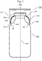
- Figure 7 is a cross-sectional view of the collar region 106, the neck region 108 and the shoulder region 109 of a glass container 100 forming a part of the closed container 300 according to the present invention, wherein geometric parameters r22, h21 and c21 are illustrated. Further parameters shown in that figure are, for example, the upper collar angle c22, the collar facet angle c23, the total collar height plus neck height h3 and the shoulder angle c51.
- Figures 8 and 9 show a glass container 100 that is a part of the closed container 300 according to the present invention in a cross-sectional view.
- Glass container 100 has a total height h1 and a centre axis 101.
- the glass container 100 comprises in a direction from the top 102 to the bottom 103 top region 104 that comprises an opening 105, a collar region 106 comprising a collar following the top region 104, wherein the outer diameter of the glass container 100 in the collar region 106 is d2 (see figure 9 ), a transition region 107 that connects the collar region 106 with a neck region 108, the neck region 108 comprising a neck, wherein the outer diameter of the glass container 100 in the neck region 108 is d3 (see figure 9 ) and wherein the inner diameter of the glass container 100 in the neck region 108 is d4 (see figure 9 ), a shoulder region 109 comprising a shoulder, a body region 110 comprising a body that follows the shoulder region 109, wherein the glass container
- FIG 10 shows a press-fit cap 200 that is a part of the closed container 300 according to the present invention in a cross-sectional view.
- the press-fit cap 200 comprises a cylindrical body 201 having an upper end 202 and a lower end 203 and at least two engaging clips 204 that are arranged at the inside of the cylindrical body 201, each clip 204 preferably comprising retaining portions 205 inclined upwardly, wherein the engaging clips 204 are adapted and arranged in such a manner that, when the press-fit cap 200 is pressed over the collar region 106 of the glass container 100 in order to close the glass container 100, the engaging clips 204, preferably by means of the retaining portions 205, engage so as to contact the outside of the glass container 100 in the transition region 107 between the collar region 106 and the neck region 108.
- the cylindrical body 201 has an inner diameter d6 and it is preferably made of a polymer such as polybutylene terephthalate.
- a cage 206 located inside of the cylindrical body 201 comprises the at least two engaging clips 204, wherein cage 206 is preferably made of a polymer such as polycarbonate.
- the press-fit cap 200 may further comprise a removable cap 207 that is located on top of the cylindrical body 201, wherein the removable cap 207 is preferably made of a polymer such as polypropylene.
- Both, the cylindrical body 201 and the cage 206 at the top of the press-fit cap 200 comprise and opening which is accessible if the cap 207 is removed.
- Figure 11A and 11B show two different closed containers 300 according to the present invention in a cross-sectional view. These containers differ from each other in that different parts of the press-fit cap 200 from the area at the bottom end 203 of the press-fit cap 200 that is closest to the outer surface of the should region 109.
- the lower end of the cylindrical body 201 is the part at the lower end 203 of the press-fit cap 200 that is closest to the should region 109 if the glass container 100 is closed with the press-fit cap.
- the lower end of the cage 206 that is located inside of the cylindrical body 201 is the part at the lower end 203 of the press-fit cap 200 that is closest to the should region 109 if the glass container 100 is closed with the press-fit cap.
- Figure 12 shows a closed container 300 according to the present invention, that in addition to the glass container 100 and the press-fit cap 200 further comprises a rubber stopper 400.
- the rubber stopper 400 comprises a first portion 401 that rests on the top region 104 of the glass container 100 and a second portion 402 that is inserted into the opening 105 of the top region 104. If such a rubber stopper 400 is used in combination with a press-fit cap 200 as shown in figure 10 , the first cylindrical portion 401 of the rubber stopper 400 is at least in part accessible if the cap 207 on top of the press-fit cap 200 is removed.
- Liquids can thus be removed from the glass container 100 by, for example, inserting the needle of a syringe centrally through the rubber stopper 400 into the glass container 100.
- the first portion 401 of the rubber stopper 400 has that shape of a disc-shaped flange having a diameter that approximately has the size d2 (i. e. the size of the outer diameter of the glass container 100 in the collar region 106).
- Attached to the lower side of the first portion 401 of the rubber stopper 400 is the second portion 402 that may shaped in the form of tubular legs that may be formed to be continuous to a lower surface side of the flange portion 401.
- notches may be provided at two locations in a circumferential direction of such a leg portion.
- the outer diameter of the second portion 402 is preferably slightly larger than the inner diameter d4 of the glass container 100 in the neck region 108 in order to ensure that the glass container 100 is sufficiently sealed when the second portion 402 of the rubber stopper 400 is introduced into the opening 105 of the top region 104.
Abstract
A) a glass container (100) having a total height h1, being characterized by a centre axis (101) and comprising a shoulder region (106);
B) a press-fit cap (200) by means of which the glass container (100) is closed comprising a cylindrical body (201) having an upper end (202) and a lower end (203);
wherein P is any given point at the lower end (203) of the press-fit cap (200) that is located above the shoulder region (109) and that lies on a straight line (113) running parallel to the centre axis (101) and hitting the outer surface of the shoulder region (109) at a point Q, wherein among these points P at the lower end (203) of the press-fit cap (200) point P' is the one that has the smallest distance to its corresponding point Q' and wherein the distance between points P' and Q' on the straight line (113) is in a range from 0.17 to 8.4 mm.
Description
- The present invention related to a closed container comprising a glass container and a press-fit cap by means of which the glass container is closed. The invention also relates to the use of a press-fit cap to close a glass container and a process for preparing a closed container.
- In the pharmaceutical industry, containers are used for the primary packaging of drugs. Among the traditionally most used materials is a glass container, as it ensures stability, visibility, endurance, rigidity, moisture resistance, ease of capping, and economy. The glass containers for medicinal purposes currently on the market include glass vials made from glass tubing and blow-molded glass containers.
- Medicaments such as vaccines are often stored in such glass vials prior to use. Vials typically include a body region that is typically cylindrical in shape and has a collar- and a neck region at the top of the vial. The neck- and collar region define a mouth for receiving the medicament into an interior chamber defined in the body region. Normally, the vials are filled with medicament, often followed by a lyophilization step, and then a pre-sterilized cap or closure device is installed to seal the medicament within the vial.
- The vial cap is typically a four-piece assembly often referred to as a "press-fit cap" that includes a cap, a stopper, a cage that usually holds the stopper in the assembly and a body. The cage is located in the inside of the press-fit cap and comprises flexible engaging clips that, when the press-fit cap is pressed over the collar region of the glass container in order to introduce the stopper into the opening for a closure of the vial, engage so as to contact the outside of the vial at a defined position. Such a four-piece assembly is, for example, commercially available under the tradename RayDyLyo® (Raygroup SASU; France).
- The above-described vial caps have to fulfill several requirements. On the one hand, they must ensure that the contents of the vials are hermetically sealed from the environment. Since the vials are usually closed with the vial caps in a fully automated process, for example within a lyophilization plant, it must be ensured that - irrespective of the production-related variations in the dimensions between the individual vials, particularly in the collar region, in the neck region, in the transition region between the collar region and the neck region and in the should region - the stoppers are always pressed completely into the opening of the vials. On the other hand, the vial caps must be firmly seated on the vials in such a way as to prevent unintentional removal of the vial caps and thus also unintentional manipulation of the contents of the vials.
- In general, it is an object of the present invention to at least partly overcome a disadvantage arising from the prior art. It is a further object of the invention to provide an assembly of a glass container and a press-fit cap that, particularly when being used in an automated process in which a glass container is filled with a medicinal product and is subsequently closed by pressing the press-fit cap onto the top of the glass container, not only ensures a complete closure of all the glass containers used in such a process, but at the same time also leads to a closed container from which the press-fit cap cannot simply be removed by means of mechanical forces.
- A contribution to at least partly solving at least one, preferably more than one, of the above objects is made by the independent claims. The dependent claims provide preferred embodiments which contribute to at least partly solving at least one of the objects.
- A contribution to solving at least one of the objects according to the invention is made by a 1st embodiment of a closed container comprising
- A) a glass container, preferably a glass container in the form of a vial, and
- B) a press-fit cap by means of which the glass container is closed;
wherein- A) the glass container has a total height h1 and is characterized by a centre axis, wherein the glass container comprises in a direction from the top (102) to the bottom:
- I) a top region that comprises an opening;
- II) a collar region comprising a collar with a collar height h21 following the top region, wherein the outer diameter of the glass container in the collar region is d2;
- III) a transition region that connects the collar region with a neck region;
- IV) the neck region comprising a neck, wherein the outer diameter of the glass container in the neck region is d3 and wherein the inner diameter of the glass container in the neck region is d4;
- V) a shoulder region comprising a shoulder;
- VI) a body region comprising a body that follows the shoulder region, wherein the glass container in the body region has an outer diameter d1;
- VII) a heel region comprising a heel that follows the body region;
and - VIII) a bottom region comprising a bottom that follows the heel region and that closes the glass container at the bottom;
- wherein the outer contour of the top region comprises in the following order:
- IA) a first outer surface inclined downwards towards the collar region,
- IB) a convex curved, circular arc-shaped area adjacent to the first outer surface;
- IC) a second outer surface adj acent to the convex curved, circular arc-shaped area and being substantially parallel to the centre axis;
- wherein the outer contour of the transition region that connects the collar region with the neck region comprises in the following order:
- IIIA) a convex curved, circular arc-shaped area having a lower collar radius r24;
- IIIB) a concave curved, circular arc-shaped area having a collar and neck radius r22; wherein the outer contour of the transition region further comprises a turning point located between the convex curved, circular arc-shaped area and the concave curved, circular arc-shaped area and wherein a tangent line applied at this turning point encloses a lower collar angle c21 with an axis perpendicular to the centre axis;
- wherein the outer contour of the top region comprises in the following order:
- B) the press-fit cap comprises a cylindrical body having an upper end and a lower end and at least two engaging clips that are arranged at the inside of the cylindrical body, each engaging clip preferably comprising retaining portions inclined upwardly, wherein the clips are adapted and arranged in such a manner that, when the press-fit cap is pressed over the collar region of the glass container in order to close the glass container, the engaging clips, preferably by means of the retaining portions, engage so as to contact the outside of the glass container in the transition region between the collar region and the neck region,
- A) the glass container has a total height h1 and is characterized by a centre axis, wherein the glass container comprises in a direction from the top (102) to the bottom:
- A contribution to solving at least one of the objects according to the invention is also made by a 1st embodiment of a plurality of closed containers, each closed container comprising
- A) a glass container, preferably a glass container in the form of a vial, and
- B) a press-fit cap by means of which the glass container is closed;
wherein- A) the glass container has a total height h1 and is characterized by a centre axis, wherein the glass container comprises in a direction from the top (102) to the bottom:
- I) a top region that comprises an opening;
- II) a collar region comprising a collar with a collar height h21 following the top region, wherein the outer diameter of the glass container in the collar region is d2;
- III) a transition region that connects the collar region with a neck region;
- IV) the neck region comprising a neck, wherein the outer diameter of the glass container in the neck region is d3 and wherein the inner diameter of the glass container in the neck region is d4;
- V) a shoulder region comprising a shoulder;
- VI) a body region comprising a body that follows the shoulder region, wherein the glass container in the body region has an outer diameter d1;
- VII) a heel region comprising a heel that follows the body region;
and - VIII) a bottom region comprising a bottom that follows the heel region and that closes the glass container at the bottom;
- wherein the outer contour of the top region comprises in the following order:
- IA) a first outer surface inclined downwards towards the collar region,
- IB) a convex curved, circular arc-shaped area adjacent to the first outer surface;
- IC) a second outer surface adj acent to the convex curved, circular arc-shaped area and being substantially parallel to the centre axis;
- wherein the outer contour of the transition region that connects the collar region with the neck region comprises in the following order:
- IIIA) a convex curved, circular arc-shaped area having a lower collar radius r24;
- IIIB) a concave curved, circular arc-shaped area having a collar and neck radius r22;
- wherein the outer contour of the top region comprises in the following order:
- B) the press-fit cap comprises a cylindrical body having an upper end and a lower end and at least two engaging clips that are arranged at the inside of the cylindrical body, each engaging clip preferably comprising retaining portions inclined upwardly, wherein the engaging clips are adapted and arranged in such a manner that, when the press-fit cap is pressed over the collar region of the glass container in order to close the glass container, the engaging clips, preferably by means of the retaining portions, engage so as to contact the outside of the glass container in the transition region between the collar region and the neck region,
- A) the glass container has a total height h1 and is characterized by a centre axis, wherein the glass container comprises in a direction from the top (102) to the bottom:
- "A plurality of closed" in the sense of the present invention preferably comprises at least 10 closed containers, preferably at least 25 closed containers, more preferably at least 50 closed containers, even more preferably at least 100 closed containers even more preferably at least 200 closed containers and most preferably at least 400 closed containers. Furthermore, the plurality of closed containers preferably has been collected arbitrarily and particularly has not been selected with regard to any property. For example, the plurality closed containers may be the group of closed containers which are packed together in a typical transport tray.
- Surprisingly, it has been discovered that by controlling the distance between the shoulder region of a glass container to the lowest point of a press-fit cap by means of which the glass container is closed to be within the very narrow range of 0.17 to 8.4 mm not only ensures a complete closure of the glass container, but at the same time also leads to a closed container from which the press-fit cap cannot simply be removed by means of mechanical forces, especially a mechanical lever.
- In view of the rotation symmetry of both, the glass container and the press-fit cap, the distance between points P' and Q' is usually the same along a circle located above the shoulder region, wherein the centre axis runs through the centre point of the circle and wherein the circle is lying in a plane that is perpendicular to the centre axis, provided that the press-fit cap is placed straight on the glass container.
- In a preferred embodiment of the closed container and of the plurality of closed containers according tom the present invention, d2 in the closed container or in at least 75 %, preferably in at least 85 %, more preferably in at least 95 % and most preferably in each closed container contained in the plurality of closed containers is in a range from 11.7 to 13.2 mm or in a range from 17.8 to 20.2 mm, preferably in a range from 11.9 to 12.7 mm or in a range from 18.0 to 19.7 mm and more preferably in a range from 12.1 to 12.6 mm or in a range from 18.2 to 19.6 mm. This preferred embodiment is a 2nd embodiment of the closed container and of the plurality of closed containers according to the present invention, that preferably depends on the 1st embodiment.
- In a further preferred embodiment of the closed container and of the plurality of closed containers according tom the present invention, d3 in the closed container or in at least 75 %, preferably in at least 85 %, more preferably in at least 95 % and most preferably in each closed container contained in the plurality of closed containers is in a range from 9.5 to 10.7 mm, in a range from 14.0 to 16.5 mm or in a range from 15.0 to 17.5 mm, preferably in a range from 9.6 to 10.4 mm, in a range from 14.1 to 16.4 mm or in a range from 15.1 to 17.4 mm and more preferably in a range from 9.7 to 10.3 mm, in a range from 14.2 to 16.3 mm or in a range from 15.2 to 17.3 mm. This preferred embodiment is a 3rd embodiment of the closed container and of the plurality of closed containers according to the present invention, that preferably depends on the 1st and the 2nd embodiment.
- In a further preferred embodiment of the closed container and of the plurality of closed containers according tom the present invention, d4 in the closed container or in at least 75 %, preferably in at least 85 %, more preferably in at least 95 % and most preferably in each closed container contained in the plurality of closed containers is in a range from 5.0 to 7.2 mm or in a range from 10.4 to 12.8 mm, preferably in a range from 5.1 to 6.8 mm or in a range from 10.5 to 12.4 mm and more preferably in a range from 5.2 to 6.7 mm or in a range from 10.6 to 12.3 mm. This preferred embodiment is a 4th embodiment of the closed container and of the plurality of closed containers according to the present invention, that preferably depends on anyone of the 1st to the 3rd embodiment.
- In a further preferred embodiment of the closed container and of the plurality of closed containers according tom the present invention, r22 in the closed container or in at least 75 %, preferably in at least 85 %, more preferably in at least 95 % and most preferably in each closed container contained in the plurality of closed containers is in a range from 0.3 to 1.0 mm, preferably in a range from 0.5 to 0.9 mm and more preferably in a range from 0.7 to 0.8 mm. This preferred embodiment is a 5th embodiment of the closed container and of the plurality of closed containers according to the present invention, that preferably depends on anyone of the 1st to the 4th embodiment.
- In a further preferred embodiment of the closed container and of the plurality of closed containers according tom the present invention, r24 in the closed container or in at least 75 %, preferably in at least 85 %, more preferably in at least 95 % and most preferably in each closed container contained in the plurality of closed containers is 0.5 mm or less, preferably 0.4 mm or less and more preferably 0.3 mm or less. This preferred embodiment is an 6th embodiment of the closed container and of the plurality of closed containers according to the present invention, that preferably depends on anyone of the 1st to the 5th embodiment.
- In a further preferred embodiment of the closed container and of the plurality of closed containers according tom the present invention, c21 in the closed container or in at least 75 %, preferably in at least 85 %, more preferably in at least 95 % and most preferably in each closed container contained in the plurality of closed containers is in a range from 3 to 20°, preferably in a range from 5 to 15° and more preferably in a range from 7 to 10°. This preferred embodiment is a 7th embodiment of the closed container and of the plurality of closed containers according to the present invention, that preferably depends on anyone of the 1st to the 6th embodiment.
- In a further preferred embodiment of the closed container and of the plurality of closed containers according tom the present invention, the outer contour of the top region further comprises a third outer surface adjacent to the first outer surface, wherein the third outer surface is inclined downwards into the inside of the glass container and which encloses an angle c24 with the centre axis, wherein c24 in the closed container or in at least 75 %, preferably in at least 85 %, more preferably in at least 95 % and most preferably in each closed container contained in the plurality of closed containers is in a range from 30 to 50°, preferably in a range from 33 to 47° and more preferably in a range from 37 to 43°. This preferred embodiment is a 8th embodiment of the closed container and of the plurality of closed containers according to the present invention, that preferably depends on anyone of the 1st to the 7th embodiment.
- In a further preferred embodiment of the closed container and of the plurality of closed containers according tom the present invention, the neck height h21 in the closed container or in at least 75 %, preferably in at least 85 %, more preferably in at least 95 % and most preferably in each closed container contained in the plurality of closed containers is in a range from 1.3 to 3.6 mm, preferably in a range from 1.5 to 3.4 mm and more preferably in a range from 1.7 to 3.3 mm. This preferred embodiment is a 9th embodiment of the closed container and of the plurality of closed containers according to the present invention, that preferably depends on anyone of the 1st to the 8th embodiment.
- In a further preferred embodiment of the closed container and of the plurality of closed containers according to the present invention, the press-fit cap comprises
- i) a cylindrical body having an inner diameter d6, preferably made of a polymer such as polybutylene terephthalate;
- ii) a cage located inside of the cylindrical body, preferably made of a polymer such as polycarbonate, wherein the cap cage comprises at least two engaging clips, each clip preferably comprising retaining portions inclined upwardly;
- iii) a removable cap located on top of the cylindrical body, preferably made of a polymer such as polypropylene;
- In this context it is particularly preferred, that d6 is at least 0.9 × d1, preferably at least 0.95 × d1 and even more preferably at least 1.0 × d1. In such an embodiment of a closed container according to the present invention it is preferably the lowest portion of the cage that is closest to the should region.
- In a further preferred embodiment of the closed container and of the plurality of closed containers according tom the present invention, the press-fit cap has a maximum outer diameter dcap in the range from 13.3 to 14.5 mm or in the range from 20.1 to 21.5 mm, preferably in the range from 13.4 to 14.4 mm or in the range from 20.2 to 21.4 mm, more preferably in the range from 13.5 to 14.3 mm or in the range from 20.3 to 21.3 mm, more preferably in the range from 13.6 to 14.2 mm or in the range from 20.4 to 21.2 mm, and more preferably in the range from 13.7 to 14.1 mm or in the range from 20.5 to 21.1 mm. This preferred embodiment is a 11th embodiment of the closed container and of the plurality of closed containers according to the present invention, that preferably depends on anyone of the 1st to the 10th embodiment
- In a further preferred embodiment of the closed container and of the plurality of closed containers according tom the present invention, the press-fit cap has a height hcap in the range from 4.5 to 7.5 mm, preferably in the range from 4.8 to 7.2 mm, more preferably in the range from 5 to 7 mm, more preferably in the range from 5.2 to 6.8 mm and more preferably in the range from 5.5 to 6.5 mm. This preferred embodiment is a 12th embodiment of the closed container and of the plurality of closed containers according to the present invention, that preferably depends on anyone of the 1st to the 11th embodiment.
- In a further preferred embodiment of the closed container and of the plurality of closed containers according tom the present invention, the closed glass container or each closed container contained in the plurality of closed containers further comprises
C) a rubber stopper,
wherein the rubber stopper comprises a first portion that rests on the top region and a second portion that is inserted into the opening of the top region. This preferred embodiment is a 13th embodiment of the closed container and of the plurality of closed containers according to the present invention, that preferably depends on anyone of the 1st to the 12th embodiment, particularly on the 12th embodiment. If such a rubber stopper is used in combination with a press-fit cap as defined in the 10th embodiment, the first cylindrical portion of the rubber stopper is at least in part accessible if the cap is removed. Liquids can thus be removed from the glass container by, for example, inserting the needle of a syringe centrally through the rubber stopper into the glass container. - Preferably, the first portion of the rubber stopper has that shape of a disc-shaped flange having a diameter that approximately has the size d2 (i. e. the size of the outer diameter of the glass container in the collar region). Attached to the lower side of the first portion of the rubber stopper is the second portion that may shaped in the form of tubular legs that may be formed to be continuous to a lower surface side of the flange portion. Also, notches may be provided at two locations in a circumferential direction of such a leg portion. The outer diameter of the second portion is preferably slightly larger than the inner diameter d4 of the glass container in the neck region in order to ensure that the glass container is sufficiently sealed when the second portion of the rubber stopper is introduced into the opening of the top region. Examples of suitable rubber stoppers are, for example, disclosed in
US 2016/0075485A1 . - In a particularly preferred embodiment of the closed container and of the plurality of closed containers according tom the present invention, in which the closed glass container or each closed container contained in the plurality of closed containers further comprises a rubber stopper, the closed glass container or each closed container contained in the plurality of closed containers may additionally comprise
D) a crimped top seal,
by means of which the rubber stopper is at least partially superimposed on the top side of the first cylindrical portion, wherein the crimped to seal surrounds the collar region of the glass container. Preferably, the crimped top seal is prepared by crimping a metallic (for example aluminum) or a polymeric (for example polypropylene) skirt under the transition region between the collar region and the neck region of the glass container. The press-fit-cap is subsequently pressed over the crimped top seal that surrounds the collar region of the glass container. - In a further preferred embodiment of the closed container and of the plurality of closed containers according tom the present invention, the closed glass container or each closed container contained in the plurality of closed containers further comprises
E) a vial adaptor. - This preferred embodiment is a 14th embodiment of the closed container and of the plurality of closed containers according to the present invention, that preferably depends on anyone of the 1st to the 13th embodiment. Preferably, the vial adaptor has an inner diameter and a height with such dimensions that the vial adaptor can be placed on the press-fit cap.
- In a further preferred embodiment of the closed container and of the plurality of closed containers according tom the present invention, the closed glass container or each closed container contained in the plurality of closed containers further comprises
F) a liquid or solid composition, preferably a liquid or solid composition comprising a pharmaceutical active ingredient, more preferably a pharmaceutical composition. - This preferred embodiment is a 15th embodiment of the closed container and of the plurality of closed containers according to the present invention, that preferably depends on anyone of the 1st to the 14th embodiment
- A contribution to solving at least one of the objects according to the invention is made by a 1st embodiment of a use of a press-fit cap B that comprises
B) a cylindrical body having an upper end and a lower end and at least two engaging clips that are arranged at the inside of the cylindrical body, each engaging clip preferably comprising retaining portions inclined upwardly, wherein the engaging clips are adapted and arranged in such a manner that, when the press-fit cap is pressed over the collar region of a glass container in order to close the glass container, the engaging clips, preferably by means of the retaining portions, engage so as to contact the outside of the glass container in the transition region between the collar region and the neck region;
to close a glass container A) wherein - A) the glass container has a total height h1 and is characterized by a centre axis, wherein the glass container comprises in a direction from the top (102) to the bottom:
- I) a top region that comprises an opening;
- II) a collar region comprising a collar with a collar height h21 following the top region, wherein the outer diameter of the glass container in the collar region is d2;
- III) a transition region that connects the collar region with a neck region;
- IV) the neck region comprising a neck, wherein the outer diameter of the glass container in the neck region is d3 and wherein the inner diameter of the glass container in the neck region is d4;
- V) a shoulder region comprising a shoulder;
- VI) a body region comprising a body that follows the shoulder region, wherein the glass container in the body region has an outer diameter d1;
- VII) a heel region comprising a heel that follows the body region;
and - VIII) a bottom region comprising a bottom that follows the heel region and that closes the glass container at the bottom;
- wherein the outer contour of the top region comprises in the following order:
- IA) a first outer surface inclined downwards towards the collar region,
- IB) a convex curved, circular arc-shaped area adjacent to the first outer surface;
- IC) a second outer surface adj acent to the convex curved, circular arc-shaped area and being substantially parallel to the centre axis;
- wherein the outer contour of the transition region that connects the collar region with the neck region comprises in the following order:
- IIIA) a convex curved, circular arc-shaped area having a lower collar radius r24;
- IIIB) a concave curved, circular arc-shaped area having a collar and neck radius r22;
- wherein the outer contour of the top region comprises in the following order:
- According to a further embodiment of the use according to the present invention, the glass container to be closed by the press-fit cap is already closed by means of a rubber stopper, wherein the rubber stopper comprises a first cylindrical portion that rests on the top region and a second cylindrical portion that is inserted into the opening of the top region. When closing such a glass container, the press-fit cap is pressed over the collar region of the glass container until the inner surface of the top region of the press-fit cap rests on the upper surface of the first cylindrical portion of the rubber stopper. This preferred embodiment is a 2nd embodiment of the use according to the present invention that preferably depends on the 1st embodiment
- According to a variant of this 1st embodiment of the use according to the present invention, the glass container further comprises a crimped top seal by means of which the rubber stopper is at least partially superimposed on the top side of the first cylindrical portion, wherein the crimped to seal surrounds the collar region of the glass container. Preferably, the crimped top seal is prepared by crimping a metallic (usually aluminum) skirt under the transition region between the collar region and the neck region of the glass container. The press-fit-cap is subsequently pressed over the crimped top seal that surrounds the collar region of the glass container.
- According to a further embodiment of the use according to the present invention, the glass container to be closed by the press-fit cap is not already closed by means of a rubber stopper. In this case a rubber stopper that comprises a first cylindrical portion and a second cylindrical portion is accommodated in the interior of the press-fit cap in such a manner that, when the press-fit cap is pressed over the collar region of the glass container, the first cylindrical portion of the rubber stopper is introduced into the opening and the second cylindrical portion of the rubber stopper rests on the top region. This preferred embodiment is a 3rd embodiment of the use according to the present invention that preferably depends on the 1st embodiment
- According to further preferred embodiment of the use according to the present invention, the glass container to be closed by the press-fit cap comprises a pharmaceutical composition. This preferred embodiment is a 4th embodiment of the use according to the present invention that preferably depends on anyone of the 1st to the 3rd embodiment.
- A contribution to solving at least one of the objects according to the invention is made by a process for preparing a closed container, the process comprising the steps:
- i) providing a glass container A) as defined in context with the use according to the present invention;
- ii) closing the glass container A) with a press-fit cap B) as defined in context with the use according to the present invention by pressing the press-fit cap over the collar region of the glass container;
- According to a first particular embodiment of the process according to the present invention, the glass container to be closed by the press-fit cap in process step ii) is already closed by means of a rubber stopper, wherein the rubber stopper comprises a first cylindrical portion that rests on the top region and a second cylindrical portion that is inserted into the opening of the top region.
- According to a second particular embodiment of the process according to the present invention, the glass container to be closed by the press-fit cap in process step ii) is not already closed by means of a rubber stopper, but is closed by means of a press-fit cap that accommodates the rubber stopper in the interior of the press-fit cap.
- The glass of the glass container can be any type of glass and may consist of any material or combination of materials which the skilled person deems suitable in the context of the invention. Preferably, the glass is suitable for pharmaceutical packaging. Particularly preferable, the glass is of type I, more preferably type I b, in accordance with the definitions of glass types in section 3.2.1 of the European Pharmacopoeia, 7th edition from 2011. Additionally, or alternatively preferable to the preceding, the glass is selected from the group consisting of a borosilicate glass, an aluminosilicate glass, soda lime glass and fused silica; or a combination of at least two thereof. For the use in this document, an aluminosilicate glass is a glass which has a content of Al2O3 of more than 8 wt.-%, preferably more than 9 wt.-%, particularly preferable in a range from 9 to 20 wt.-%, in each case based on the total weight of the glass. A preferred aluminosilicate glass has a content of B2O3 of less than 8 wt.-%, preferably at maximum 7 wt.-%, particularly preferably in a range from 0 to 7 wt.-%, in each case based on the total weight of the glass. For the use in this document, a borosilicate glass is a glass which has a content of B2O3 of at least 1 wt.-%, preferably at least 2 wt.-%, more preferably at least 3 wt.-%, more preferably at least 4 wt.-%, even more preferably at least 5 wt.-%, particularly preferable in a range from 5 to 15 wt.-%, in each case based on the total weight of the glass. A preferred borosilicate glass has a content of Al2O3 of less than 7.5 wt.-%, preferably less than 6.5 wt.-%, particularly preferably in a range from 0 to 5.5 wt.-%, in each case based on the total weight of the glass. In a further aspect, the borosilicate glass has a content of Al2O3 in a range from 3 to 7.5 wt.-%, preferably in a range from 4 to 6 wt.-%, in each case based on the total weight of the glass.
- A glass which is further preferred according to the invention is essentially free from B. Therein, the wording "essentially free from B" refers to glasses which are free from B which has been added to the glass composition by purpose. This means that B may still be present as an impurity, but preferably at a proportion of not more than 0.1 wt.-%, more preferably not more than 0.05 wt.-%, in each case based on the weight of the glass.
- In the context of the invention, every liquid pharmaceutical composition which the skilled person deems suitable to be used in a glass container, particularly in a vial that is closed with a press-fit cap, comes into consideration. A pharmaceutical composition is a composition comprising at least one active ingredient. A preferred active ingredient is a vaccine. A further preferred pharmaceutical composition is a parenterialium, i. e. a composition which is intended to be administered via the parenteral route, which may be any route which is not enteral. Parenteral administration can be performed by injection, e.g. using a needle (usually a hypodermic needle) and a syringe.
- According to a first particular embodiment of the closed container or of the plurality of closed containers according to the present invention, the closed container or each closed container in the plurality of closed containers is a vial with an overflow capacity equal to or larger than 1 ml up to maximal 5 ml, preferably a vial with a size designation "2R" according to DIN EN ISO 8362-1:2016-06, wherein it is furthermore preferred that at least one, preferably all of the following conditions i) to vi) is/are fulfilled:
- i) h1 is in a range from 34.5 to 35.5 mm, preferably in a range from 34.7 to 35.3 mm and more preferably in a range from 34.8 to 35.2 mm;
- ii) d2 is in a range from 11.7 to 13.2 mm, preferably in a range from 11.9 to 12.7 mm and more preferably in a range from 12.1 to 12.6 mm;
- iii) d3 is in a range from 9.5 to 10.5 mm, preferably in a range from 9.6 to 10.4 mm and more preferably in a range from 9.7 to 10.3 mm;
- iv) d4 is in a range from 5.0 to 7.2 mm, preferably in a range from 5.1 to 6.8 mm and more preferably in a range from 5.2 to 6.7 mm;
- v) r22 is in a range from 0.3 to 1.0 mm, preferably in a range from 0.5 to 0.9 mm and more preferably in a range from 0.7 to 0.8 mm;
- vi) c21 is in a range from 3 to 20°, preferably in a range from 5 to 15° and more preferably in a range from 7 to 10°.
- According to a second particular embodiment of the closed container or of the plurality of closed containers according to the present invention, the closed container or each closed container in the plurality of closed containers is a vial with an overflow capacity of larger than 4 ml up to maximal 8 ml, preferably a vial with a size designation "4R" according to DIN EN ISO 8362-1:2016-06, wherein it is furthermore preferred that at least one, preferably all of the following conditions i) to vi) is/are fulfilled:
- i) h1 is in a range from 44.5 to 45.5 mm, preferably in a range from 44.7 to 45.3 mm and more preferably in a range from 44.8 to 45.2 mm;
- ii) d2 is in a range from 11.7 to 13.2 mm, preferably in a range from 11.9 to 12.7 mm and more preferably in a range from 12.1 to 12.6 mm;
- iii) d3 is in a range from 9.5 to 10.5 mm, preferably in a range from 9.6 to 10.4 mm and more preferably in a range from 9.7 to 10.3 mm;
- iv) d4 is in a range from 5.0 to 7.2 mm, preferably in a range from 5.1 to 6.8 mm and more preferably in a range from 5.2 to 6.7 mm;
- v) r22 is in a range from 0.3 to 1.0 mm, preferably in a range from 0.5 to 0.9 mm and more preferably in a range from 0.7 to 0.8 mm;
- vi) c21 is in a range from 3 to 20°, preferably in a range from 5 to 15° and more preferably in a range from 7 to 10°.
- According to a third particular embodiment of the closed container or of the plurality of closed containers according to the present invention, the closed container or each closed container in the plurality of closed containers is a vial with an overflow capacity of larger than 8 ml up to maximal 10.75 ml, preferably a vial with a size designation "6R" according to DIN EN ISO 8362-1:2016-06, wherein it is furthermore preferred that at least one, preferably all of the following conditions i) to vi) is/are fulfilled:
- i) h1 is in a range from 39.5 to 40.5 mm, preferably in a range from 39.7 to 40.3 mm and more preferably in a range from 39.8 to 40.2 mm;
- ii) d2 is in a range from 17.8 to 20.2 mm, preferably in a range from 18.0 to 19.7 mm and more preferably in a range from 18.2 to 19.6 mm;
- iii) d3 is in a range from 14.0 to 16.5 mm, preferably in a range from 14.1 to 16.4 mm and more preferably in a range from 14.2 to 16.3 mm;
- iv) d4 is in a range from 10.4 to 12.8 mm, preferably in a range from 10.5 to 12.4 mm and more preferably in a range from 10.6 to 12.3 mm;
- v) r22 is in a range from 0.3 to 1.0 mm, preferably in a range from 0.5 to 0.9 mm and more preferably in a range from 0.7 to 0.8 mm;
- vi) c21 is in a range from 3 to 20°, preferably in a range from 5 to 15° and more preferably in a range from 7 to 10°.
- According to a fourth particular embodiment of the closed container or of the plurality of closed containers according to the present invention, the closed container or each closed container in the plurality of closed containers is a vial with an overflow capacity of larger than 10.75 ml up to maximal 12.5 ml, preferably a vial with a size designation "8R" according to DIN EN ISO 8362-1:2016-06, wherein it is furthermore preferred that at least one, preferably all of the following conditions i) to vi) is/are fulfilled:
- i) h1 is in a range from 44.5 to 45.5 mm, preferably in a range from 44.7 to 45.3 mm and more preferably in a range from 44.8 to 45.2 mm;
- ii) d2 is in a range from 17.8 to 20.2 mm, preferably in a range from 18.0 to 19.7 mm and more preferably in a range from 18.2 to 19.6 mm;
- iii) d3 is in a range from 14.0 to 16.5 mm, preferably in a range from 14.1 to 16.4 mm and more preferably in a range from 14.2 to 16.3 mm;
- iv) d4 is in a range from 10.4 to 12.8 mm, preferably in a range from 10.5 to 12.4 mm and more preferably in a range from 10.6 to 12.3 mm;
- v) r22 is in a range from 0.3 to 1.0 mm, preferably in a range from 0.5 to 0.9 mm and more preferably in a range from 0.7 to 0.8 mm;
- vi) c21 is in a range from 3 to 20°, preferably in a range from 5 to 15° and more preferably in a range from 7 to 10°.
- According to a fifth particular embodiment of the closed container or of the plurality of closed containers according to the present invention, the closed container or each closed container in the plurality of closed containers is a vial with an overflow capacity of larger than 12.5 ml up to maximal 16.25ml, preferably a vial with a size designation "10R" according to DIN EN ISO 8362-1:2016-06, wherein it is furthermore preferred that at least one, preferably all of the following conditions i) to vi) is/are fulfilled:
- i) h1 is in a range from 44.5 to 45.5 mm, preferably in a range from 44.7 to 45.3 mm and more preferably in a range from 44.8 to 45.2 mm;
- ii) d2 is in a range from 17.8 to 20.2 mm, preferably in a range from 18.0 to 19.7 mm and more preferably in a range from 18.2 to 19.6 mm;
- iii) d3 is in a range from 14.0 to 16.5 mm, preferably in a range from 14.1 to 16.4 mm and more preferably in a range from 14.2 to 16.3 mm;
- iv) d4 is in a range from 10.4 to 12.8 mm, preferably in a range from 10.5 to 12.4 mm and more preferably in a range from 10.6 to 12.3 mm;
- v) r22 is in a range from 0.3 to 1.0 mm, preferably in a range from 0.5 to 0.9 mm and more preferably in a range from 0.7 to 0.8 mm;
- vi) c21 is in a range from 3 to 20°, preferably in a range from 5 to 15° and more preferably in a range from 7 to 10°.
- According to a sixth particular embodiment of the closed container or of the plurality of closed containers according to the present invention, the closed container or each closed container in the plurality of closed containers is a vial with an overflow capacity of larger than 16.25 ml up to maximal 22.5ml, preferably a vial with a size designation "15R" according to DIN EN ISO 8362-1:2016-06, wherein it is furthermore preferred that at least one, preferably all of the following conditions i) to vi) is/are fulfilled:
- i) h1 is in a range from 59.5 to 60.5 mm, preferably in a range from 59.7 to 60.3 mm and more preferably in a range from 59.8 to 60.2 mm;
- ii) d2 is in a range from 17.8 to 20.2 mm, preferably in a range from 18.0 to 19.7 mm and more preferably in a range from 18.2 to 19.6 mm;
- iii) d3 is in a range from 14.0 to 16.5 mm, preferably in a range from 14.1 to 16.4 mm and more preferably in a range from 14.2 to 16.3 mm;
- iv) d4 is in a range from 10.4 to 12.8 mm, preferably in a range from 10.5 to 12.4 mm and more preferably in a range from 10.6 to 12.3 mm;
- v) r22 is in a range from 0.3 to 1.0 mm, preferably in a range from 0.5 to 0.9 mm and more preferably in a range from 0.7 to 0.8 mm;
- vi) c21 is in a range from 3 to 20°, preferably in a range from 5 to 15° and more preferably in a range from 7 to 10°.
- According to a seventh particular embodiment of the closed container or of the plurality of closed containers according to the present invention, the closed container or each closed container in the plurality of closed containers is a vial with an overflow capacity of larger than 22.5 ml up to maximal 29.25ml, preferably a vial with a size designation "20R" according to DIN EN ISO 8362-1:2016-06, wherein it is furthermore preferred that at least one, preferably all of the following conditions i) to vi) is/are fulfilled:
- i) h1 is in a range from 54.3 to 55.7 mm, preferably in a range from 54.5 to 55.5 mm and more preferably in a range from 54.6 to 55.4 mm;
- ii) d2 is in a range from 17.8 to 20.2 mm, preferably in a range from 18.0 to 19.7 mm and more preferably in a range from 18.2 to 19.6 mm;
- iii) d3 is in a range from 15.0 to 17.5 mm, preferably in a range from 15.1 to 17.4 mm and more preferably in a range from 15.2 to 17.3 mm;
- iv) d4 is in a range from 10.4 to 12.8 mm, preferably in a range from 10.5 to 12.4 mm and more preferably in a range from 10.6 to 12.3 mm;
- v) r22 is in a range from 0.3 to 1.0 mm, preferably in a range from 0.5 to 0.9 mm and more preferably in a range from 0.7 to 0.8 mm;
- vi) c21 is in a range from 3 to 20°, preferably in a range from 5 to 15° and more preferably in a range from 7 to 10°.
- According to an eight particular embodiment of the closed container or of the plurality of closed containers according to the present invention, the closed container or each closed container in the plurality of closed containers is a vial with an overflow capacity of larger than 29.25 ml up to maximal 35 ml, preferably a vial with a size designation "25R" according to DIN EN ISO 8362-1:2016-06, wherein it is furthermore preferred that at least one, preferably all of the following conditions i) to vi) is/are fulfilled:
- i) h1 is in a range from 64.3 to 65.7 mm, preferably in a range from 64.5 to 65.5 mm and more preferably in a range from 64.6 to 65.4 mm;
- ii) d2 is in a range from 17.8 to 20.2 mm, preferably in a range from 18.0 to 19.7 mm and more preferably in a range from 18.2 to 19.6 mm;
- iii) d3 is in a range from 15.0 to 17.5 mm, preferably in a range from 15.1 to 17.4 mm and more preferably in a range from 15.2 to 17.3 mm;
- iv) d4 is in a range from 10.4 to 12.8 mm, preferably in a range from 10.5 to 12.4 mm and more preferably in a range from 10.6 to 12.3 mm;
- v) r22 is in a range from 0.3 to 1.0 mm, preferably in a range from 0.5 to 0.9 mm and more preferably in a range from 0.7 to 0.8 mm;
- vi) c21 is in a range from 3 to 20°, preferably in a range from 5 to 15° and more preferably in a range from 7 to 10°.
- According to a ninth particular embodiment of the closed container or of the plurality of closed containers according to the present invention, the closed container or each closed container in the plurality of closed containers is a vial with an overflow capacity of larger than 35 ml up to maximal 49.75ml, preferably a vial with a size designation "30R" according to DIN EN ISO 8362-1:2016-06, wherein it is furthermore preferred that at least one, preferably all of the following conditions i) to vi) is/are fulfilled:
- i) h1 is in a range from 74.3 to 75.7 mm, preferably in a range from 74.5 to 75.5 mm and more preferably in a range from 74.6 to 75.4 mm;
- ii) d2 is in a range from 17.8 to 20.2 mm, preferably in a range from 18.0 to 19.7 mm and more preferably in a range from 18.2 to 19.6 mm;
- iii) d3 is in a range from 15.0 to 17.5 mm, preferably in a range from 15.1 to 17.4 mm and more preferably in a range from 15.2 to 17.3 mm;
- iv) d4 is in a range from 10.4 to 12.8 mm, preferably in a range from 10.5 to 12.4 mm and more preferably in a range from 10.6 to 12.3 mm;
- v) r22 is in a range from 0.3 to 1.0 mm, preferably in a range from 0.5 to 0.9 mm and more preferably in a range from 0.7 to 0.8 mm;
- vi) c21 is in a range from 3 to 20°, preferably in a range from 5 to 15° and more preferably in a range from 7 to 10°.
- According to a tenth particular embodiment of the closed container or of the plurality of closed containers according to the present invention, the closed container or each closed container in the plurality of closed containers is a vial with an overflow capacity of larger than 49.75 ml up to maximal 92.5ml, preferably a vial with a size designation "50R" according to DIN EN ISO 8362-1:2016-06, wherein it is furthermore preferred that at least one, preferably all of the following conditions i) to vi) is/are fulfilled:
- i) h1 is in a range from 72.3 to 73.7 mm, preferably in a range from 72.5 to 73.5 mm and more preferably in a range from 72.6 to 73.4 mm;
- ii) d2 is in a range from 17.8 to 20.2 mm, preferably in a range from 18.0 to 19.7 mm and more preferably in a range from 18.2 to 19.6 mm;
- iii) d3 is in a range from 15.0 to 17.5 mm, preferably in a range from 15.1 to 17.4 mm and more preferably in a range from 15.2 to 17.3 mm;
- iv) d4 is in a range from 10.4 to 12.8 mm, preferably in a range from 10.5 to 12.4 mm and more preferably in a range from 10.6 to 12.3 mm;
- v) r22 is in a range from 0.3 to 1.0 mm, preferably in a range from 0.5 to 0.9 mm and more preferably in a range from 0.7 to 0.8 mm;
- vi) c21 is in a range from 3 to 20°, preferably in a range from 5 to 15° and more preferably in a range from 7 to 10°.
- According to an eleventh particular embodiment of the closed container or of the plurality of closed containers according to the present invention, the closed container or each closed container in the plurality of closed containers is a vial with an overflow capacity of larger than 92.5 ml up to maximal 150 ml, preferably a vial with a size designation "100R" according to DIN EN ISO 8362-1:2016-06, wherein it is furthermore preferred that at least one, preferably all of the following conditions i) to vi) is/are fulfilled:
- i) h1 is in a range from 99.2 to 100.8 mm, preferably in a range from 99.4 to 100.6 mm and more preferably in a range from 99.5 to 100.5 mm;
- ii) d2 is in a range from 17.8 to 20.2 mm, preferably in a range from 18.0 to 19.7 mm and more preferably in a range from 18.2 to 19.6 mm;
- iii) d3 is in a range from 15.0 to 17.5 mm, preferably in a range from 15.1 to 17.4 mm and more preferably in a range from 15.2 to 17.3 mm;
- iv) d4 is in a range from 10.4 to 12.8 mm, preferably in a range from 10.5 to 12.4 mm and more preferably in a range from 10.6 to 12.3 mm;
- v) r22 is in a range from 0.3 to 1.0 mm, preferably in a range from 0.5 to 0.9 mm and more preferably in a range from 0.7 to 0.8 mm;
- vi) c21 is in a range from 3 to 20°, preferably in a range from 5 to 15° and more preferably in a range from 7 to 10°.
- The following measurement methods are to be used in the context of the invention. Unless otherwise specified, the measurements have to be carried out at an ambient temperature of 23°C, an ambient air pressure of 100 kPa (0.986 atm) and a relative atmospheric humidity of 50 %.
- Parameters of h1, h21, h21, r22, r24 and c21 are preferably determined in at least one cross-sectional view of the vial, wherein the cross-sectional view lies with-in a plane that comprises the entire center axis of the vial.
- For the determination of lower collar angle c21 the section of the collar's surface is divided into four quarters and the middle two quarters are used for applying the fit in form of the least squares method, preferably in the cross-sectional view.
- The neck height h21, the collar height h21, the collar and neck radius r22 and the lower collar radius r24 are determined as shown in
figures 4A, 4B ,5A ,5B and6 , respectively. - The inner or outer diameters d1, d2, d3 and d4 and the total height h1 of the glass container at a given position are determined in accordance with DIN ISO 8362-1. The outer diameter d2 of the collar region is measured under consideration of the largest radial extend of the collar, as can be exemplarily taken from
Fig. 6 . - Unless otherwise specified in the description or the particular figure:
- Figure 1
- shows a
closed container 300 according to the present invention; - Figure 2
- is a cross-sectional view of the
top region 104 and thecollar region 106 of aglass container 200 forming a part of theclosed container 300 according to the present invention; - Figure 3
- illustrated how the distance between a given point P at the
lower end 203 of the press-fit cap 200 and a corresponding point Q that is located above theshoulder region 109 is determined and how point P' and Q' are selected; - Figures 4A,B
- illustrate how to determine the collar height h21, the neck height h21 and the lower collar angle c21; shows a side view of
container 100 according to the present invention; - Figure 5
- illustrate how to determine the collar and neck radius r22;
- Figure 6
- illustrates how to determine the lower collar radius r24;
- Figure 7
- is a cross-sectional view of the
collar region 106, theneck region 108 and theshoulder region 109 of aglass container 100 forming a part of theclosed container 300 according to the present invention, wherein geometric parameters r22, h21 and c21 are illustrated; - Figure 8
- shows a
glass container 100 that is a part of theclosed container 300 according to the present invention in a cross-sectional view; - Figure 9
- shows a
glass container 100 that is a part of theclosed container 300 according to the present invention in a cross-sectional view; - Figure 10
- shows a press-
fit cap 200 that is a part of theclosed container 300 according to the present invention in a cross-sectional view; - Figures 11A,B
- show two different
closed containers 300 according to the present invention in a cross-sectional view; - Figure 12
- shows a
closed container 300 according to the present invention, that in addition to theglass container 100 and the press-fit cap 200 further comprises arubber stopper 400. -
Figure 1 shows aclosed container 300 according to the present invention. Theclosed container 300 comprises aglass container 100 having acentre axis 101 and a press-fit-cap 200 by means of which theglass container 100 is closed. Theglass container 100 comprises, among other parts, acollar region 106, aneck region 108, atransition region 107 that connects thecollar region 106 with theneck region 108 and ashoulder region 109. The press-fit cap 200 comprises acylindrical body 201 and one or moreengaging clips 204 that are arranged at the inside of the cylindrical body, each clip preferably comprising retainingportions 205 inclined upwardly. The engagingclips 204 are adapted and arranged in such a manner that, when the press-fit cap 200 is pressed over thecollar region 106 of theglass container 100 in order to close theglass container 100, the engagingclips 204, preferably by means of the retainingportions 205, engage so as to contact the outside of theglass container 100 in thetransition region 107 between thecollar region 106 and theneck region 108. In theclosed container 300 according to the present invention the distance between points P' and Q' on thestrait line 113 is in a range from 0.17 to 8.4 mm, wherein point P' is the point at thelower end 203 of the press-fit cap 200 that has the smallest distance to the outer surface of theshoulder region 109. -
Figure 2 is a cross-sectional view of thetop region 104 and thecollar region 106 of aglass container 200 forming a part of theclosed container 300 according to the present invention. As can be seen, the 104 comprises a firstouter surface 104a inclined downwards towards thecollar region 106, a convex curved, circular arc-shapedarea 104b adjacent to the firstouter surface 104a (see alsofigure 5B ) and a secondouter surface 104c adjacent to the convex curved, circular arc-shapedarea 104b and being substantially parallel to thecentre axis 101. The outer contour of thetransition region 107 that connects thecollar region 106 with theneck region 108 comprises a convex curved, circular arc-shapedarea 107a having a lower collar radius r24 (see alsofigure 6 ) and a concave curved, circular arc-shapedarea 107b having a collar and neck radius r22 (see alsofigure 5A ) wherein the outer contour of thetransition region 107 further comprises aturning point 107c located between the convex curved, circular arc-shapedarea 107a and the concave curved, circular arc-shapedarea 107b and wherein atangent line 107d applied at thisturning point 107c encloses a lower collar angle c21 (see alsofigure 4B ) with an axis perpendicular to thecentre axis 101. -
Figure 3 illustrated how the distance between a given point P at thelower end 203 of the press-fit cap 200 that is located above theshoulder region 109 and that lies on astraight line 113 running parallel to thecentre axis 101 and hitting the outer surface of theshoulder region 109 at a point Q. Among these points P at thelower end 203 of the press-fit cap 200 point P' is the one that has the smallest distance to its corresponding point Q'. -
Figure 4A illustrates how to determine the neck height h21. The neck height h21 is the vertical distance between a first and a second point, wherein the first point is the intersection point of the straight line g1 used for determining the lower collar angle and a vertical line g2 which, preferably in the cross-sectional view, crosses the most outer circumferential point of the container's neck in theneck region 108, and wherein the second point is the intersection point of the straight line g1 used for determining the shoulder angle and the aforementioned vertical line g2. Preferably, the vertical distance is measured along a direction parallel to thecenter axis 101 of theglass container 100. Preferably, the vertical line extends in a direction parallel to the center axis of the vial. -
Figure 4B illustrates how to determine the collar height h21 and the lower collar angle c21. The collar height h21 is the vertical distance between the plane g3 defined by the top of the vial and a specific point, wherein the specific point is obtained as an intersection point of on the one hand a vertical straight line g4 which, preferably in the cross-sectional view, touches the most outer circumference point of the container'scollar region 106 and on the other hand another straight line g5, wherein another straight line is the straight line used for determining the lower collar angle c21. Preferably, the vertical distance is measured along a direction parallel to the center axis of the vial. Preferably, the vertical straight line extends in a direction parallel to the center axis of the vial. The lower collar angle c21 is the angle between on the one hand a straight line and on the other hand a plane g6 oriented perpendicular to the center axis of the vial, wherein the straight line is determined, preferably in the cross-sectional view, by the least squares method at a section of the surface of thecollar region 106 which has a normal vector pointing in a direction towards at least one plane which comprises the bottom of the vial. Preferably, the section of the surface of thecollar region 106 is divided into four quarters and the middle two quarters are used for applying the fit in form of the least squares method, preferably in the cross-sectional view. -
Figure 5 illustrates how to determine the collar and neck radius r22. The collar and neck radius r22 is the radius of the circle which has a first straight line and a second straight line as tangents, wherein, preferably in the cross-sectional view, the first straight line is parallel to thecenter axis 101 of theglass container 100 and crosses the outer point of theneck region 108, which preferably constitutes the outer diameter d3 of theneck region 108, wherein, preferably in the cross-sectional view, the second straight line is the other straight line used for determining the collar height h21. -
Figure 6 illustrates how to determine the lower collar radius r24. The lower collar radius r24 is the radius of a circle crossing at least three points, wherein, preferably in the cross-sectional view, the first point of the at least three ones is the point where a first tangent touches the circle, wherein, preferably in the cross-sectional view, the first tangent is the straight line used for determining the lower collar angle c21, wherein, preferably in the cross-sectional view, the second point of the at least three ones is the point where a second tangent touches the circle, wherein, preferably in the cross-sectional view, the second tangent is parallel to thecenter axis 101 of theglass container 100 and crosses the outer point of thecollar region 106, which preferably constitutes the outer diameter d2 of thecollar region 106, wherein, preferably in the cross-sectional view, a straight line can be defined which starts at a specific intersection point being the intersection point of the first and second tangent and extends upwards towards the glass container, which straight line encloses an angle of 45° with the second tangent, wherein, preferably in the cross-sectional view, the third point is an intersection point of the straight line and the contour of thecollar region 106 of theglass container 100, the intersection point being the closest one to the specific intersection point. In other words (see for referenceFigure 6 ): the lower collar radius r24 is determined using a projected line, the edge of the glass container and two tangent points. A circle is drawn using the tangents and the glass container edge whose radius is the lower collar angle. The projected line is 45° from vertical and starts at the collar height h21 on the line defined in the measurement of the outer diameter d2 of thecollar region 106. The edge of the vial seen on this projected line is used, along with the edge defined in the outer diameter d2 of thecollar region 106 and the lower collar angle c21 to define the three points, which are used to create the circle. Preferably, vertical indicates a direction parallel to thecenter axis 101 of the glass container. -
Figure 7 is a cross-sectional view of thecollar region 106, theneck region 108 and theshoulder region 109 of aglass container 100 forming a part of theclosed container 300 according to the present invention, wherein geometric parameters r22, h21 and c21 are illustrated. Further parameters shown in that figure are, for example, the upper collar angle c22, the collar facet angle c23, the total collar height plus neck height h3 and the shoulder angle c51. -
Figures 8 and9 show aglass container 100 that is a part of theclosed container 300 according to the present invention in a cross-sectional view.Glass container 100 has a total height h1 and acentre axis 101. Theglass container 100 comprises in a direction from the top 102 to the bottom 103top region 104 that comprises anopening 105, acollar region 106 comprising a collar following thetop region 104, wherein the outer diameter of theglass container 100 in thecollar region 106 is d2 (seefigure 9 ), atransition region 107 that connects thecollar region 106 with aneck region 108, theneck region 108 comprising a neck, wherein the outer diameter of theglass container 100 in theneck region 108 is d3 (seefigure 9 ) and wherein the inner diameter of theglass container 100 in theneck region 108 is d4 (seefigure 9 ), ashoulder region 109 comprising a shoulder, abody region 110 comprising a body that follows theshoulder region 109, wherein theglass container 100 in thebody region 110 has an outer diameter d1 (seefigure 9 ), aheel region 111 comprising a heel that follows thebody region 110 and abottom region 112 comprising a bottom that follows theheel region 111 and that closes theglass container 100 at the bottom 103. -
Figure 10 shows a press-fit cap 200 that is a part of theclosed container 300 according to the present invention in a cross-sectional view. The press-fit cap 200 comprises acylindrical body 201 having anupper end 202 and alower end 203 and at least twoengaging clips 204 that are arranged at the inside of thecylindrical body 201, eachclip 204 preferably comprising retainingportions 205 inclined upwardly, wherein the engagingclips 204 are adapted and arranged in such a manner that, when the press-fit cap 200 is pressed over thecollar region 106 of theglass container 100 in order to close theglass container 100, the engagingclips 204, preferably by means of the retainingportions 205, engage so as to contact the outside of theglass container 100 in thetransition region 107 between thecollar region 106 and theneck region 108. In the embodiment of a press-fit cap 200 as shown infigure 10 thecylindrical body 201 has an inner diameter d6 and it is preferably made of a polymer such as polybutylene terephthalate. Preferably, acage 206 located inside of thecylindrical body 201 comprises the at least twoengaging clips 204, whereincage 206 is preferably made of a polymer such as polycarbonate. As also shown infigure 10 , the press-fit cap 200 may further comprise aremovable cap 207 that is located on top of thecylindrical body 201, wherein theremovable cap 207 is preferably made of a polymer such as polypropylene. Both, thecylindrical body 201 and thecage 206 at the top of the press-fit cap 200 comprise and opening which is accessible if thecap 207 is removed. -
Figure 11A and 11B show two differentclosed containers 300 according to the present invention in a cross-sectional view. These containers differ from each other in that different parts of the press-fit cap 200 from the area at thebottom end 203 of the press-fit cap 200 that is closest to the outer surface of the shouldregion 109. In the embodiment shown infigure 11A the lower end of thecylindrical body 201 is the part at thelower end 203 of the press-fit cap 200 that is closest to the shouldregion 109 if theglass container 100 is closed with the press-fit cap. In the embodiment shown infigure 11B the lower end of thecage 206 that is located inside of thecylindrical body 201 is the part at thelower end 203 of the press-fit cap 200 that is closest to the shouldregion 109 if theglass container 100 is closed with the press-fit cap. -
Figure 12 shows aclosed container 300 according to the present invention, that in addition to theglass container 100 and the press-fit cap 200 further comprises arubber stopper 400. As shown in that figure, therubber stopper 400 comprises afirst portion 401 that rests on thetop region 104 of theglass container 100 and asecond portion 402 that is inserted into theopening 105 of thetop region 104. If such arubber stopper 400 is used in combination with a press-fit cap 200 as shown infigure 10 , the firstcylindrical portion 401 of therubber stopper 400 is at least in part accessible if thecap 207 on top of the press-fit cap 200 is removed. Liquids can thus be removed from theglass container 100 by, for example, inserting the needle of a syringe centrally through therubber stopper 400 into theglass container 100. In the embodiment of arubber stopper 400 as shown infigure 12 thefirst portion 401 of therubber stopper 400 has that shape of a disc-shaped flange having a diameter that approximately has the size d2 (i. e. the size of the outer diameter of theglass container 100 in the collar region 106). Attached to the lower side of thefirst portion 401 of therubber stopper 400 is thesecond portion 402 that may shaped in the form of tubular legs that may be formed to be continuous to a lower surface side of theflange portion 401. Also notches may be provided at two locations in a circumferential direction of such a leg portion. The outer diameter of thesecond portion 402 is preferably slightly larger than the inner diameter d4 of theglass container 100 in theneck region 108 in order to ensure that theglass container 100 is sufficiently sealed when thesecond portion 402 of therubber stopper 400 is introduced into theopening 105 of thetop region 104. -
- 100
- glass container
- 101
- centre axis of the
glass container 100 - 102
- top of the
glass container 100 - 103
- bottom of the
glass container 100 - 104
- top region
- 104a
- first outer surface of the outer contour of the
top region 104 - 104b
- convex curved, circular arc-shaped area of the outer contour of the
top region 104 adjacent to the firstouter surface 104a - 104c
- second outer surface of the outer contour of the
top region 104 adjacent to the convex curved, circular arc-shapedarea 104b - 105
- opening
- 106
- collar region
- 107
- transition region that connects the
collar region 106 and theneck region 108 - 107a
- convex curved, circular arc-shaped area of the outer contour of the
transition region 107 - 107b
- concave curved, circular arc-shaped area of the outer contour of the
transition region 107 - 107c
- turning point
- 107d
- tangent line
- 108
- neck region
- 109
- shoulder region
- 110
- body region
- 111
- heel region
- 112
- bottom region
- 113
- straight line running parallel to the
centra axis 101 - 200
- press-fit cap
- 201
- cylindrical body
- 202
- upper end of
cylindrical body 201 - 203
- lower end of
cylindrical body 201 - 204
- engaging clips located inside of the
cylindrical body 201 - 205
- retaining portions of the engaging
clips 204 - 206
- cage located inside of the
cylindrical body 201 - 207
- removable cap
- 300
- closed container according to the present invention
- 400
- rubber stopper
- 401
- first portion of the
rubber stopper 400 - 402
- second portion of the
rubber stopper 400
region and that lies on a straight line running parallel to the centre axis and hitting the outer surface of the shoulder region at a point Q, wherein among these points P at the lower end of the press-fit cap point P' is the one that has the smallest distance to its corresponding point Q',
wherein the distance between points P' and Q' on the straight line is in a range from 0.17 to 8.4 mm, preferably in a range from 0.2 to 8 mm and more preferably in a range from 0.3 to 7.5 mm, most preferably 0.4 to 7 mm, most preferably 0.5 to 6 mm, most preferably 0.6 to 5 mm, most preferably 0.7 to 4 mm, most preferably 0.8 to 3 mm, most preferably 0.9 to 2 mm, most preferably 1 to 1.5 mm.
wherein for at least 90 %, preferably for at least 95 %, more preferably for at least 97 % and most preferably for at least 99 % of the closed containers in the plurality of closed containers the distance between points P' and Q' on the straight line is in a range from 0.17 to 8.4 mm, preferably in a range from 0.2 to 8 mm, more preferably in a range from 0.3 to 7.5 mm, most preferably 0.4 to 7 mm, most preferably 0.5 to 6 mm, most preferably 0.6 to 5 mm, most preferably 0.7 to 4 mm, most preferably 0.8 to 3 mm, most preferably 0.9 to 2 mm, most preferably 1 to 1.5 mm.
wherein the distance between points P' and Q' on the straight line is in a range from 0.17 to 8.4 mm, preferably in a range from 0.2 to 8 mm and more preferably in a range from 0.3 to 7.5 mm, most preferably 0.4 to 7 mm, most preferably 0.5 to 6 mm, most preferably 0.6 to 5 mm, most preferably 0.7 to 4 mm, most preferably 0.8 to 3 mm, most preferably 0.9 to 2 mm, most preferably 1 to 1.5 mm. In this context it is particularly preferred that the press-fit cap is designed according to the 10th embodiment of the closed container according to the present invention and that the glass container is designed according to anyone of the 2nd to the 9th embodiment.
wherein the distance between points P' and Q' on the straight line is in a range from 0.17 to 8.4 mm, preferably in a range from 0.2 to 8 mm and more preferably in a range from 0.3 to 7.5 mm, most preferably 0.4 to 7 mm, most preferably 0.5 to 6 mm, most preferably 0.6 to 5 mm, most preferably 0.7 to 4 mm, most preferably 0.8 to 3 mm, most preferably 0.9 to 2 mm, most preferably 1 to 1.5 mm.
Claims (15)
- A closed container (300) comprisingA) a glass container (100) andB) a press-fit cap (200) by means of which the glass container (100) is closed;whereinA) the glass container (100) has a total height h1 and is characterized by a centre axis (101), wherein the glass container comprises in a direction from the top (102) to the bottom (103):I) a top region (104) that comprises an opening (105);II) a collar region (106) comprising a collar with a collar height h21 following the top region (104), wherein the outer diameter of the glass container (100) in the collar region (106) is d2;III) a transition region (107) that connects the collar region (106) with a neck region (108);IV) the neck region (108) comprising a neck, wherein the outer diameter of the glass container (100) in the neck region (108) is d3 and wherein the inner diameter of the glass container (100) in the neck region (108) is d4;V) a shoulder region (109) comprising a shoulder;VI) a body region (110) comprising a body that follows the shoulder region (109), wherein the glass container (100) in the body region (110) has an outer diameter d1;VII) a heel region (111) comprising a heel that follows the body region (110); andVIII) a bottom region (112) comprising a bottom that follows the heel region (111) and that closes the glass container (100) at the bottom (103);- wherein the outer contour of the top region (104) comprises in the following order:IA) a first outer surface (104a) inclined downwards towards the collar region (106),IB) a convex curved, circular arc-shaped area (104b) adjacent to the first outer surface (104a);IC) a second outer surface (104c) adjacent to the convex curved, circular arc-shaped area (104b) and being substantially parallel to the centre axis (101);- wherein the outer contour of the transition region (107) that connects the collar region (106) with the neck region (108) comprises in the following order:IIIA) a convex curved, circular arc-shaped area (107a) having a lower collar radius r24;IIIB) a concave curved, circular arc-shaped area (107b) having a collar and neck radius r22;wherein the outer contour of the transition region (107) further comprises a turning point (107c) located between the convex curved, circular arc-shaped area (107a) and the concave curved, circular arc-shaped area (107b) and wherein a tangent line (107d) applied at this turning point (107c) encloses a lower collar angle c21 with an axis perpendicular to the centre axis (101);B) the press-fit cap (200) comprises a cylindrical body (201) having an upper end (202) and a lower end (203) and at least two engaging clips (204) that are arranged at the inside of the cylindrical body (201), wherein the engaging clips (204) are adapted and arranged in such a manner that, when the press-fit cap (200) is pressed over the collar region (106) of the glass container (100) in order to close the glass container (100), the engaging clips (204) engage so as to contact the outside of the glass container (100) in the transition region (107) between the collar region (106) and the neck region (108);wherein P is any given point at the lower end (203) of the press-fit cap (200) that is located above the shoulder region (109) and that lies on a straight line (113) running parallel to the centre axis (101) and hitting the outer surface of the shoulder region (109) at a point Q, wherein among these points P at the lower end (203) of the press-fit cap (200) point P' is the one that has the smallest distance to its corresponding point Q',
wherein the distance between points P' and Q' on the strait line (113) is in a range from 0.17 to 8.4 mm. - The closed container (300) according to claim 1, wherein d2 is in a range from 11.7 to 13.2 mm or in a range from 17.8 to 20.2 mm.
- The closed container (300) according to claim 1 or 2, wherein d3 is in a range from 9.5 to 10.5 mm, in a range from 14.0 to 16.5 mm or in a range from 15.0 to 17.5 mm.
- The closed container (300) according to anyone of claims 1 to 3, wherein d4 is in a range from 5.0 to 7.2 mm or in a range from 10.4 to 12.8 mm.
- The closed container (300) according to anyone of claims 1 to 4, wherein r22 is in a range from 0.3 to 1.0 mm.
- The closed container (300) according to anyone of claims 1 to 5, wherein r24 is 0.5 mm or less.
- The closed container (300) according to anyone of claims 1 to 6, wherein c21 is in a range from 3 to 20°.
- The closed container (300) according to anyone of claims 1 to 7, wherein the outer contour of the top region (104) further comprises a third outer surface adjacent to the first outer surface (104a), wherein the third outer surface is inclined downwards into the inside of the glass container (100) and which encloses an angle c24 with the centre axis (101), wherein c24 is in a range from 30 to 50°.
- The closed container (300) according to anyone of claims 1 to 8, wherein the neck height h21 is in a range from 1.3 to 3.6 mm.
- The closed container (300) according to anyone of claims 1 to 9, wherein the press-fit cap (200) has a maximum outer diameter dcap in the range from 13.4 to 14.4 mm or in the range from 20.1 to 21.5 mm.
- The closed container (300) according to anyone of claims 1 to 10, wherein the press-fit cap (200) has a height hcap in the range from 4.5 to 7.5 mm
- The closed container (300) according to anyone of claims 1 to 11, wherein the glass container (300) further comprises
C) a rubber stopper (400),
wherein the rubber stopper (400) comprises a first portion (401) that rests on the top region (104) and a second portion (402) that is inserted into the opening (105) of the top region (104). - The closed container (300) according to anyone of claims 1 to 10, wherein the glass container (300) further comprises
E) a vial adaptor (500). - The closed container (300) according to anyone of claims 1 to 11, wherein the glass container (300) further comprises
F) a liquid or a solid composition, preferably comprising a pharmaceutical active ingredient. - Use of a press-fit cap (200) B as defined in claim 1 to close a glass container (100) A as defined in claim 1, wherein, when the press-fit cap (200) is pressed over the collar region (104) of the glass container (100) in order to close the glass container (100) and when the engaging clips (204) engage so as to contact the outside of the glass container (100) in the transition region (107) between the collar region (106) and the neck region (108), P is any given point at the lower end of the press-fit cap (200) that is located above the shoulder region (109) and that lies on a straight line (113) running parallel to the centre axis (101) and hitting the outer surface of the shoulder region (109) at a point Q, wherein among these points P at the lower end (203) of the press-fit cap (200) point P' is the one that has the smallest distance to its corresponding point Q',
wherein the distance between points P' and Q' on the straight line (113) is in a range from 0.17 to 8.4 mm.
Priority Applications (3)
| Application Number | Priority Date | Filing Date | Title |
|---|---|---|---|
| EP21177452.6A EP4098572A1 (en) | 2021-06-02 | 2021-06-02 | Container closed with a press-fit cap |
| US17/830,200 US20220387257A1 (en) | 2021-06-02 | 2022-06-01 | Container closed with a press-fit cap |
| CN202210624159.5A CN115432289A (en) | 2021-06-02 | 2022-06-02 | Container closed by press-fit lid |
Applications Claiming Priority (1)
| Application Number | Priority Date | Filing Date | Title |
|---|---|---|---|
| EP21177452.6A EP4098572A1 (en) | 2021-06-02 | 2021-06-02 | Container closed with a press-fit cap |
Publications (1)
| Publication Number | Publication Date |
|---|---|
| EP4098572A1 true EP4098572A1 (en) | 2022-12-07 |
Family
ID=76250236
Family Applications (1)
| Application Number | Title | Priority Date | Filing Date |
|---|---|---|---|
| EP21177452.6A Pending EP4098572A1 (en) | 2021-06-02 | 2021-06-02 | Container closed with a press-fit cap |
Country Status (3)
| Country | Link |
|---|---|
| US (1) | US20220387257A1 (en) |
| EP (1) | EP4098572A1 (en) |
| CN (1) | CN115432289A (en) |
Families Citing this family (1)
| Publication number | Priority date | Publication date | Assignee | Title |
|---|---|---|---|---|
| TW202327941A (en) * | 2021-09-30 | 2023-07-16 | 美商康寧公司 | Glass containers for storing pharmaceutical compositions |
Citations (5)
| Publication number | Priority date | Publication date | Assignee | Title |
|---|---|---|---|---|
| FR2893922A1 (en) * | 2005-11-30 | 2007-06-01 | Biocorp Rech Et Dev Sa | Plug device for medication container e.g. glass vial, has manoeuvring element comprising annular edge engaged between external skirt of ring of cover and lip that forms locking unit and radially extends towards central axis of ring |
| US20120046636A1 (en) * | 2007-04-23 | 2012-02-23 | Plastmed Ltd. | Method and apparatus for contamination-free transfer of a hazardous drug |
| US20140209603A1 (en) * | 2011-06-08 | 2014-07-31 | Antoine Aneas | Stopping device and container comprising such a device |
| US20160075485A1 (en) | 2014-09-16 | 2016-03-17 | Sumitomo Rubber Industries, Ltd. | Medical rubber closure and method for manufacturing the same |
| US20180141729A1 (en) * | 2013-12-02 | 2018-05-24 | Antonio Mutterle | Closure assembly for bottle, associated bottle and assembly method |
-
2021
- 2021-06-02 EP EP21177452.6A patent/EP4098572A1/en active Pending
-
2022
- 2022-06-01 US US17/830,200 patent/US20220387257A1/en active Pending
- 2022-06-02 CN CN202210624159.5A patent/CN115432289A/en active Pending
Patent Citations (5)
| Publication number | Priority date | Publication date | Assignee | Title |
|---|---|---|---|---|
| FR2893922A1 (en) * | 2005-11-30 | 2007-06-01 | Biocorp Rech Et Dev Sa | Plug device for medication container e.g. glass vial, has manoeuvring element comprising annular edge engaged between external skirt of ring of cover and lip that forms locking unit and radially extends towards central axis of ring |
| US20120046636A1 (en) * | 2007-04-23 | 2012-02-23 | Plastmed Ltd. | Method and apparatus for contamination-free transfer of a hazardous drug |
| US20140209603A1 (en) * | 2011-06-08 | 2014-07-31 | Antoine Aneas | Stopping device and container comprising such a device |
| US20180141729A1 (en) * | 2013-12-02 | 2018-05-24 | Antonio Mutterle | Closure assembly for bottle, associated bottle and assembly method |
| US20160075485A1 (en) | 2014-09-16 | 2016-03-17 | Sumitomo Rubber Industries, Ltd. | Medical rubber closure and method for manufacturing the same |
Non-Patent Citations (1)
| Title |
|---|
| "European Pharmacopoeia", 2011 |
Also Published As
| Publication number | Publication date |
|---|---|
| CN115432289A (en) | 2022-12-06 |
| US20220387257A1 (en) | 2022-12-08 |
Similar Documents
| Publication | Publication Date | Title |
|---|---|---|
| EP2887919B1 (en) | Liquid drug transfer devices | |
| AU697521B2 (en) | Apparatus for combining a first liquid component and a second solid or liquid component by means of reduced pressure under sterile conditions | |
| US4193402A (en) | Bottle stopper and method of using said stopper | |
| US20020193777A1 (en) | Device for connection between a vessel and a container and ready-to-use assembly comprising same | |
| EP0932552A1 (en) | Container closure assembly | |
| US20050159724A1 (en) | Needleless access vial | |
| US8714384B2 (en) | Device for stopping a container, and container provided with such a device | |
| EP4098572A1 (en) | Container closed with a press-fit cap | |
| US9731952B2 (en) | Ampule breaking aid | |
| CN106794932B (en) | The metering device being made of plastics | |
| JP2021184862A (en) | Sealing device for making it possible to collect composition, packaging assembly comprising such sealing device, and collection and packaging methods | |
| ES2772750T3 (en) | Plastic container and procedure for the manufacture of such a container | |
| KR20210005529A (en) | Vial with optimized neck for improved side compression performance | |
| USH2101H1 (en) | Container with retaining member | |
| KR100901049B1 (en) | Container for inhalation anesthetic | |
| US3654926A (en) | Mixing vial | |
| JP7428476B2 (en) | Glass container with improved bottom geometry | |
| KR20210005528A (en) | Vial with optimized neck for improved side compression performance | |
| CN110498596A (en) | Glass container with improved bottom geometry | |
| EP2216265A1 (en) | Containment for bottles, vials and like containers | |
| EP4303195A1 (en) | Glass container with increased breakage resistance | |
| CN220558366U (en) | Glass syringe barrel with longitudinal axis L barrel and syringe | |
| WO2022137609A1 (en) | Rubber plug | |
| Smith et al. | Containers | |
| EP3798142A1 (en) | Holding device for the flexible treatment of pharmaceutical packaging materials |
Legal Events
| Date | Code | Title | Description |
|---|---|---|---|
| PUAI | Public reference made under article 153(3) epc to a published international application that has entered the european phase |
Free format text: ORIGINAL CODE: 0009012 |
|
| STAA | Information on the status of an ep patent application or granted ep patent |
Free format text: STATUS: THE APPLICATION HAS BEEN PUBLISHED |
|
| AK | Designated contracting states |
Kind code of ref document: A1 Designated state(s): AL AT BE BG CH CY CZ DE DK EE ES FI FR GB GR HR HU IE IS IT LI LT LU LV MC MK MT NL NO PL PT RO RS SE SI SK SM TR |
|
| RAP3 | Party data changed (applicant data changed or rights of an application transferred) |
Owner name: SCHOTT AG Owner name: SCHOTT PHARMA SCHWEIZ AG |
|
| RAP1 | Party data changed (applicant data changed or rights of an application transferred) |
Owner name: SCHOTT PHARMA AG & CO. KGAA Owner name: SCHOTT PHARMA SCHWEIZ AG |
|
| STAA | Information on the status of an ep patent application or granted ep patent |
Free format text: STATUS: REQUEST FOR EXAMINATION WAS MADE |
|
| P01 | Opt-out of the competence of the unified patent court (upc) registered |
Effective date: 20230512 |
|
| 17P | Request for examination filed |
Effective date: 20230605 |
|
| RBV | Designated contracting states (corrected) |
Designated state(s): AL AT BE BG CH CY CZ DE DK EE ES FI FR GB GR HR HU IE IS IT LI LT LU LV MC MK MT NL NO PL PT RO RS SE SI SK SM TR |