EP4098371B1 - Nick- und giersystem und verfahren zur betätigung eines vorrichtungskopfs - Google Patents
Nick- und giersystem und verfahren zur betätigung eines vorrichtungskopfs Download PDFInfo
- Publication number
- EP4098371B1 EP4098371B1 EP22169755.0A EP22169755A EP4098371B1 EP 4098371 B1 EP4098371 B1 EP 4098371B1 EP 22169755 A EP22169755 A EP 22169755A EP 4098371 B1 EP4098371 B1 EP 4098371B1
- Authority
- EP
- European Patent Office
- Prior art keywords
- yaw
- pitch
- frame
- axis
- actuator
- Prior art date
- Legal status (The legal status is an assumption and is not a legal conclusion. Google has not performed a legal analysis and makes no representation as to the accuracy of the status listed.)
- Active
Links
Images










Classifications
-
- B—PERFORMING OPERATIONS; TRANSPORTING
- B05—SPRAYING OR ATOMISING IN GENERAL; APPLYING FLUENT MATERIALS TO SURFACES, IN GENERAL
- B05B—SPRAYING APPARATUS; ATOMISING APPARATUS; NOZZLES
- B05B15/00—Details of spraying plant or spraying apparatus not otherwise provided for; Accessories
- B05B15/60—Arrangements for mounting, supporting or holding spraying apparatus
- B05B15/68—Arrangements for adjusting the position of spray heads
-
- B—PERFORMING OPERATIONS; TRANSPORTING
- B64—AIRCRAFT; AVIATION; COSMONAUTICS
- B64F—GROUND OR AIRCRAFT-CARRIER-DECK INSTALLATIONS SPECIALLY ADAPTED FOR USE IN CONNECTION WITH AIRCRAFT; DESIGNING, MANUFACTURING, ASSEMBLING, CLEANING, MAINTAINING OR REPAIRING AIRCRAFT, NOT OTHERWISE PROVIDED FOR; HANDLING, TRANSPORTING, TESTING OR INSPECTING AIRCRAFT COMPONENTS, NOT OTHERWISE PROVIDED FOR
- B64F5/00—Designing, manufacturing, assembling, cleaning, maintaining or repairing aircraft, not otherwise provided for; Handling, transporting, testing or inspecting aircraft components, not otherwise provided for
-
- B—PERFORMING OPERATIONS; TRANSPORTING
- B05—SPRAYING OR ATOMISING IN GENERAL; APPLYING FLUENT MATERIALS TO SURFACES, IN GENERAL
- B05B—SPRAYING APPARATUS; ATOMISING APPARATUS; NOZZLES
- B05B13/00—Machines or plants for applying liquids or other fluent materials to surfaces of objects or other work by spraying, not covered by groups B05B1/00 - B05B11/00
- B05B13/002—Machines or plants for applying coating liquids or other fluent materials by inkjet
-
- B—PERFORMING OPERATIONS; TRANSPORTING
- B05—SPRAYING OR ATOMISING IN GENERAL; APPLYING FLUENT MATERIALS TO SURFACES, IN GENERAL
- B05B—SPRAYING APPARATUS; ATOMISING APPARATUS; NOZZLES
- B05B13/00—Machines or plants for applying liquids or other fluent materials to surfaces of objects or other work by spraying, not covered by groups B05B1/00 - B05B11/00
- B05B13/02—Means for supporting work; Arrangement or mounting of spray heads; Adaptation or arrangement of means for feeding work
- B05B13/0207—Means for supporting work; Arrangement or mounting of spray heads; Adaptation or arrangement of means for feeding work the work being an elongated body, e.g. wire or pipe
- B05B13/0214—Means for supporting work; Arrangement or mounting of spray heads; Adaptation or arrangement of means for feeding work the work being an elongated body, e.g. wire or pipe the liquid or other fluent material being applied to the whole periphery of the cross section of the elongated body
-
- B—PERFORMING OPERATIONS; TRANSPORTING
- B05—SPRAYING OR ATOMISING IN GENERAL; APPLYING FLUENT MATERIALS TO SURFACES, IN GENERAL
- B05B—SPRAYING APPARATUS; ATOMISING APPARATUS; NOZZLES
- B05B13/00—Machines or plants for applying liquids or other fluent materials to surfaces of objects or other work by spraying, not covered by groups B05B1/00 - B05B11/00
- B05B13/02—Means for supporting work; Arrangement or mounting of spray heads; Adaptation or arrangement of means for feeding work
- B05B13/0278—Arrangement or mounting of spray heads
-
- B—PERFORMING OPERATIONS; TRANSPORTING
- B05—SPRAYING OR ATOMISING IN GENERAL; APPLYING FLUENT MATERIALS TO SURFACES, IN GENERAL
- B05B—SPRAYING APPARATUS; ATOMISING APPARATUS; NOZZLES
- B05B13/00—Machines or plants for applying liquids or other fluent materials to surfaces of objects or other work by spraying, not covered by groups B05B1/00 - B05B11/00
- B05B13/02—Means for supporting work; Arrangement or mounting of spray heads; Adaptation or arrangement of means for feeding work
- B05B13/04—Means for supporting work; Arrangement or mounting of spray heads; Adaptation or arrangement of means for feeding work the spray heads being moved during spraying operation
- B05B13/0405—Means for supporting work; Arrangement or mounting of spray heads; Adaptation or arrangement of means for feeding work the spray heads being moved during spraying operation with reciprocating or oscillating spray heads
- B05B13/041—Means for supporting work; Arrangement or mounting of spray heads; Adaptation or arrangement of means for feeding work the spray heads being moved during spraying operation with reciprocating or oscillating spray heads with spray heads reciprocating along a straight line
- B05B13/0415—Means for supporting work; Arrangement or mounting of spray heads; Adaptation or arrangement of means for feeding work the spray heads being moved during spraying operation with reciprocating or oscillating spray heads with spray heads reciprocating along a straight line the angular position of the spray heads relative to the straight line being modified during the reciprocating movement
-
- B—PERFORMING OPERATIONS; TRANSPORTING
- B05—SPRAYING OR ATOMISING IN GENERAL; APPLYING FLUENT MATERIALS TO SURFACES, IN GENERAL
- B05B—SPRAYING APPARATUS; ATOMISING APPARATUS; NOZZLES
- B05B13/00—Machines or plants for applying liquids or other fluent materials to surfaces of objects or other work by spraying, not covered by groups B05B1/00 - B05B11/00
- B05B13/02—Means for supporting work; Arrangement or mounting of spray heads; Adaptation or arrangement of means for feeding work
- B05B13/04—Means for supporting work; Arrangement or mounting of spray heads; Adaptation or arrangement of means for feeding work the spray heads being moved during spraying operation
- B05B13/0436—Installations or apparatus for applying liquid or other fluent material to elongated bodies, e.g. light poles, pipes
-
- B—PERFORMING OPERATIONS; TRANSPORTING
- B05—SPRAYING OR ATOMISING IN GENERAL; APPLYING FLUENT MATERIALS TO SURFACES, IN GENERAL
- B05B—SPRAYING APPARATUS; ATOMISING APPARATUS; NOZZLES
- B05B15/00—Details of spraying plant or spraying apparatus not otherwise provided for; Accessories
- B05B15/60—Arrangements for mounting, supporting or holding spraying apparatus
- B05B15/65—Mounting arrangements for fluid connection of the spraying apparatus or its outlets to flow conduits
- B05B15/652—Mounting arrangements for fluid connection of the spraying apparatus or its outlets to flow conduits whereby the jet can be oriented
- B05B15/654—Mounting arrangements for fluid connection of the spraying apparatus or its outlets to flow conduits whereby the jet can be oriented using universal joints
-
- B—PERFORMING OPERATIONS; TRANSPORTING
- B05—SPRAYING OR ATOMISING IN GENERAL; APPLYING FLUENT MATERIALS TO SURFACES, IN GENERAL
- B05D—PROCESSES FOR APPLYING FLUENT MATERIALS TO SURFACES, IN GENERAL
- B05D1/00—Processes for applying liquids or other fluent materials
- B05D1/02—Processes for applying liquids or other fluent materials performed by spraying
-
- B—PERFORMING OPERATIONS; TRANSPORTING
- B41—PRINTING; LINING MACHINES; TYPEWRITERS; STAMPS
- B41J—TYPEWRITERS; SELECTIVE PRINTING MECHANISMS, i.e. MECHANISMS PRINTING OTHERWISE THAN FROM A FORME; CORRECTION OF TYPOGRAPHICAL ERRORS
- B41J2/00—Typewriters or selective printing mechanisms characterised by the printing or marking process for which they are designed
- B41J2/005—Typewriters or selective printing mechanisms characterised by the printing or marking process for which they are designed characterised by bringing liquid or particles selectively into contact with a printing material
- B41J2/01—Ink jet
-
- B—PERFORMING OPERATIONS; TRANSPORTING
- B41—PRINTING; LINING MACHINES; TYPEWRITERS; STAMPS
- B41J—TYPEWRITERS; SELECTIVE PRINTING MECHANISMS, i.e. MECHANISMS PRINTING OTHERWISE THAN FROM A FORME; CORRECTION OF TYPOGRAPHICAL ERRORS
- B41J25/00—Actions or mechanisms not otherwise provided for
-
- B—PERFORMING OPERATIONS; TRANSPORTING
- B41—PRINTING; LINING MACHINES; TYPEWRITERS; STAMPS
- B41J—TYPEWRITERS; SELECTIVE PRINTING MECHANISMS, i.e. MECHANISMS PRINTING OTHERWISE THAN FROM A FORME; CORRECTION OF TYPOGRAPHICAL ERRORS
- B41J25/00—Actions or mechanisms not otherwise provided for
- B41J25/304—Bodily-movable mechanisms for print heads or carriages movable towards or from paper surface
- B41J25/316—Bodily-movable mechanisms for print heads or carriages movable towards or from paper surface with tilting motion mechanisms relative to paper surface
-
- B—PERFORMING OPERATIONS; TRANSPORTING
- B41—PRINTING; LINING MACHINES; TYPEWRITERS; STAMPS
- B41J—TYPEWRITERS; SELECTIVE PRINTING MECHANISMS, i.e. MECHANISMS PRINTING OTHERWISE THAN FROM A FORME; CORRECTION OF TYPOGRAPHICAL ERRORS
- B41J3/00—Typewriters or selective printing or marking mechanisms characterised by the purpose for which they are constructed
- B41J3/407—Typewriters or selective printing or marking mechanisms characterised by the purpose for which they are constructed for marking on special material
- B41J3/4073—Printing on three-dimensional objects not being in sheet or web form, e.g. spherical or cubic objects
-
- B—PERFORMING OPERATIONS; TRANSPORTING
- B64—AIRCRAFT; AVIATION; COSMONAUTICS
- B64F—GROUND OR AIRCRAFT-CARRIER-DECK INSTALLATIONS SPECIALLY ADAPTED FOR USE IN CONNECTION WITH AIRCRAFT; DESIGNING, MANUFACTURING, ASSEMBLING, CLEANING, MAINTAINING OR REPAIRING AIRCRAFT, NOT OTHERWISE PROVIDED FOR; HANDLING, TRANSPORTING, TESTING OR INSPECTING AIRCRAFT COMPONENTS, NOT OTHERWISE PROVIDED FOR
- B64F5/00—Designing, manufacturing, assembling, cleaning, maintaining or repairing aircraft, not otherwise provided for; Handling, transporting, testing or inspecting aircraft components, not otherwise provided for
- B64F5/10—Manufacturing or assembling aircraft, e.g. jigs therefor
-
- B—PERFORMING OPERATIONS; TRANSPORTING
- B05—SPRAYING OR ATOMISING IN GENERAL; APPLYING FLUENT MATERIALS TO SURFACES, IN GENERAL
- B05B—SPRAYING APPARATUS; ATOMISING APPARATUS; NOZZLES
- B05B12/00—Arrangements for controlling delivery; Arrangements for controlling the spray area
- B05B12/08—Arrangements for controlling delivery; Arrangements for controlling the spray area responsive to condition of liquid or other fluent material to be discharged, of ambient medium or of target ; responsive to condition of spray devices or of supply means, e.g. pipes, pumps or their drive means
- B05B12/12—Arrangements for controlling delivery; Arrangements for controlling the spray area responsive to condition of liquid or other fluent material to be discharged, of ambient medium or of target ; responsive to condition of spray devices or of supply means, e.g. pipes, pumps or their drive means responsive to conditions of ambient medium or target, e.g. humidity, temperature position or movement of the target relative to the spray apparatus
- B05B12/122—Arrangements for controlling delivery; Arrangements for controlling the spray area responsive to condition of liquid or other fluent material to be discharged, of ambient medium or of target ; responsive to condition of spray devices or of supply means, e.g. pipes, pumps or their drive means responsive to conditions of ambient medium or target, e.g. humidity, temperature position or movement of the target relative to the spray apparatus responsive to presence or shape of target
-
- B—PERFORMING OPERATIONS; TRANSPORTING
- B05—SPRAYING OR ATOMISING IN GENERAL; APPLYING FLUENT MATERIALS TO SURFACES, IN GENERAL
- B05B—SPRAYING APPARATUS; ATOMISING APPARATUS; NOZZLES
- B05B12/00—Arrangements for controlling delivery; Arrangements for controlling the spray area
- B05B12/08—Arrangements for controlling delivery; Arrangements for controlling the spray area responsive to condition of liquid or other fluent material to be discharged, of ambient medium or of target ; responsive to condition of spray devices or of supply means, e.g. pipes, pumps or their drive means
- B05B12/12—Arrangements for controlling delivery; Arrangements for controlling the spray area responsive to condition of liquid or other fluent material to be discharged, of ambient medium or of target ; responsive to condition of spray devices or of supply means, e.g. pipes, pumps or their drive means responsive to conditions of ambient medium or target, e.g. humidity, temperature position or movement of the target relative to the spray apparatus
- B05B12/124—Arrangements for controlling delivery; Arrangements for controlling the spray area responsive to condition of liquid or other fluent material to be discharged, of ambient medium or of target ; responsive to condition of spray devices or of supply means, e.g. pipes, pumps or their drive means responsive to conditions of ambient medium or target, e.g. humidity, temperature position or movement of the target relative to the spray apparatus responsive to distance between spray apparatus and target
Definitions
- the present disclosure relates generally to actuation systems and, more particularly, to a system for actuating a device along multiple axes.
- the painting of an aircraft is a challenging process due to the large amount of surface area and unique geometry of aircraft surfaces.
- the nose and tail of an aircraft are typically highly contoured, which presents challenges in applying coatings in a precise manner.
- Adding to the challenge are complex paint schemes associated with an aircraft livery.
- the livery of an airline may include images or designs that have complex geometric shapes and color combinations.
- an aircraft livery may include the name and logo of the airline, which may be applied to different locations on the aircraft such as the fuselage and the vertical tail.
- the process of applying the livery to the aircraft surfaces must be carried out with a high level of precision to meet aesthetic requirements, and to ensure that the coating thickness is within desired tolerances to meet aircraft performance (e.g., weight) requirements.
- One method of painting an aircraft involves the use of individual robotic devices.
- Each robotic device includes an end effector mounted on a robotic arm.
- the robotic arm of each robotic device moves the end effector over the aircraft surfaces while the end effector dispenses any one of a variety of different paint colors, such as for applying an aircraft livery.
- the use of robotic devices reduces the amount of time required for aircraft painting relative to conventional manual methods that involve masking, painting, and demasking, the use of a single end effector on each robotic device results in a relative lengthy painting process.
- each treatment device includes a plurality of device heads.
- the devices heads must be assembled in close proximity to each other to allow for a high level of precision in applying the livery.
- each device head must be capable of being actuated along multiple axes to ensure that each device head is oriented complementary to the changing contours of the aircraft surfaces as the array of treatment devices is moved along the length of the aircraft.
- Existing mechanisms for actuating devices along multiple axes involve the use of rotary actuators. Unfortunately, rotary actuators are bulky, and are therefore difficult to package within a small area.
- EP 2 740 563 A1 discloses a processing device, a processing machine and a method for moving a machining head.
- EP 3 351 308 A1 discloses an assembly for treating contoured surface of commercial aircraft.
- the pitch-yaw actuation system includes a pitch frame, a yaw frame, a pitch actuator, a yaw actuator, and a universal joint assembly.
- the pitch frame is configured to be pivotably coupled to a device frame via a pitch hinge having a pitch axis.
- the yaw frame is pivotably coupled to the pitch frame via a yaw hinge having a yaw axis orthogonal to the pitch axis.
- the pitch actuator is configured to pivot the pitch frame about the pitch axis.
- the yaw actuator is configured to pivot the yaw frame about the yaw axis.
- the universal joint assembly couples the yaw actuator to the yaw frame.
- the universal joint assembly includes a linear guide mechanism having a guide mechanism axis.
- the universal joint assembly includes a universal joint that is slidably coupled to the linear guide mechanism.
- the guide mechanism axis is oriented at an angle that allows the universal joint to move in a manner accommodating misalignment of the yaw actuator with the yaw frame during pivoting of at least one of the pitch frame and the yaw frame.
- a device head assembly which includes a head frame and a pitch-yaw actuation system.
- the pitch-yaw actuation system includes a pitch frame, a yaw frame, a pitch actuator, a yaw actuator, and a universal joint assembly.
- the pitch frame is coupled to the head frame via a pitch hinge having a pitch axis.
- the yaw frame is coupled to the pitch frame via a yaw hinge having a yaw axis orthogonal to the pitch axis.
- the yaw frame is configured to receive a device head.
- the pitch actuator is coupled to the head frame and is configured to pivot the pitch frame about the pitch axis.
- the yaw actuator is coupled to the head frame and is configured to pivot the yaw frame about the yaw axis.
- the universal joint assembly is configured to couple the yaw actuator to the yaw frame.
- the universal joint assembly includes a linear guide mechanism having a guide mechanism axis.
- the universal joint assembly includes a universal joint that is slidably couplable to the linear guide mechanism.
- the guide mechanism axis is oriented at an angle allowing the universal j oint to move relative to the linear guide mechanism in a manner accommodating misalignment of the yaw actuator with the yaw frame during pivoting of the pitch frame and the yaw frame.
- a method of actuating a device head which includes pivoting, using a pitch actuator, a pitch frame about a pitch axis of a pitch hinge coupling the pitch frame to a head frame.
- the method includes pivoting, using a yaw actuator, a yaw frame about a yaw axis of a yaw hinge coupling the yaw frame to the pitch frame.
- the yaw axis is oriented orthogonal to the pitch axis.
- the yaw actuator is coupled to the yaw frame via a linear guide mechanism and a universal joint slidably coupled to the linear guide mechanism.
- the method also includes moving the universal joint relative to the linear guide mechanism in a manner accommodating misalignment of the yaw actuator with the yaw frame during pivoting of at least one of the pitch frame and the yaw frame.
- FIG. 1-4 shown in Figures 1-4 is an example of a treatment device system 100 for treating the article surfaces 422 of an article 420.
- the treatment device system 100 includes an upper treatment device support assembly 102, and a lower treatment device support assembly 104, each configured to support an array 120 of treatment devices 122.
- the article 420 is a fuselage 426 of an aircraft 424 having a vertical tail 430 and a pair of horizontal tails 432.
- the fuselage 426 is shown supported on the floor 404 of a treatment facility 400 using fuselage support stands 428.
- each treatment device support assembly 102, 104 are interconnected by a plurality of device actuation systems 130 ( Figure 4 ) for actuating the treatment devices 122.
- the device actuation systems 130 are configured to translate and/or rotate the treatment devices 122 in a manner to position each treatment device 122 complementary to an article surface 422 over which the treatment device system 100 is being moved.
- each treatment device 122 includes a device frame 124, and each treatment device 122 has one or more device heads 210, which are shown arranged in rows and columns, and which are supported by the device frame 124.
- each device head 210 includes a pitch-yaw actuation system 230 ( Figure 14 ) for pivoting the device head 210 about a pitch axis 240 ( Figures 10-13 ) and a yaw axis 282 ( Figures 10-13 ).
- each device head 210 is configured to orient the device head 210 complementary (e.g., locally normal) to the contour of an area of the article surface 422 ( Figure 1 ) immediately adjacent to the device head 210 as the treatment devices 122 are moved over the article 420 ( Figure 1 ).
- Each of the device heads 210 is configured to dispense a treatment (not shown) toward and/or onto an article surface 422.
- the treatment may be a coating, such as a primer, a paint, a clear coat, or a sealant.
- each of the device heads 210 is an inkjet printhead 214 (e.g., a piezoelectric printhead or a thermal printhead) configured to precisely dispense ink onto the surfaces of the fuselage 426 as the treatment devices 122 are moved along the fuselage 426 for printing an aircraft livery.
- the device heads 210 may be configured to dispense other types of treatments or substances, such as a solvent, an adhesive, a lubricant, abrasive particles, or any type of gas, liquid, semi-solid, or solid (e.g., particles) substance.
- the device heads 210 may be configured to emit radiation (e.g., electromagnetic radiation) for performing any one of a variety of operations on an article surface 422.
- the treatment device system 100 may be implemented for treating any one of a variety of different types of articles 420, and is not limited to treating an aircraft 424.
- the treatment device system 100 may be implemented for treating vehicles such as ships, trains, or other ground-based motor vehicles such as trucks and automobiles.
- the treatment device system 100 may be implemented for treating stationary objects including, but not limited to, buildings, architectural objects, walls, and/or any one of a variety of other types of structures, systems, subsystems, assemblies, or subassemblies.
- the upper treatment device support assembly 102 includes a central pillar 106 coupled to an overhead gantry 402 ( Figure 2 ).
- the fuselage 426 is oriented parallel to the lengthwise direction of the overhead gantry 402, allowing the upper treatment device support assembly 102 to move the treatment devices 122 along the length of the fuselage 426.
- a support structure base 108 is shown coupled to the central pillar 106.
- On each of opposing sides of the support structure base 108 is a pillar pivot joint 110 coupling an attachment pillar 112 to the support structure base 108.
- At the lower end of each attachment pillar 112 is an arm pivot joint 116 coupling a pair of attachment arms 114 to the attachment pillar 112.
- the ends of the attachment arms 114 are respectively coupled via arm pivot joints 116 to opposite sides of an array 120 of treatment devices 122.
- the upper treatment device support assembly 102 supports two arrays 120 of treatment devices 122.
- the lower treatment device support assembly 104 is configured similar to the upper treatment device support assembly 102.
- the lower treatment device support assembly 104 includes a central pillar 106, which is supported on a pit gantry 408 mounted in a pit 410 extending along a lengthwise direction below the floor 404 in parallel relation to the overhead gantry 402.
- a support structure base 108 is mounted on the upper end of the central pillar 106.
- a pair of pillar pivot joints 110 on opposite sides of the support structure base 108 respectively couple a pair of attachment pillars 112 to the support structure base 108.
- the attachment pillars 112 extend upwardly through a pair of floor openings 406.
- each attachment pillar 112 At the upper end of each attachment pillar 112 is an arm pivot joint 116 coupling a pair of attachment arms 114 to the attachment pillar 112. The ends of the pair of attachment arms 114 extending from each attachment pillar 112 are coupled to opposite sides of an array 120 of treatment devices 122.
- the lower treatment device support assembly 104 supports two arrays 120 of treatment devices 122.
- the upper treatment device support assembly 102 supporting two arrays 120 of treatment devices 122. Also shown is the lower treatment device support assembly 104 supporting two arrays 120 of treatment devices 122.
- the attachment pillars 112 are rotatable about the pillar pivot joints 110, and the attachment arms 114 are rotatable about the arm pivot joints 116. The pivotability of the attachment pillars 112 and the attachment arms 114 allows the arrays 120 of treatment devices 122 to be positioned complementary to a variety of articles of different sizes and shapes.
- FIG. 7 shown is a single array 120 of treatment devices 122 of the lower treatment device support assembly 104 ( Figure 6 ).
- the array 120 is supported on opposite ends respectively by a pair of attachment arms 114.
- Each treatment device 122 includes a device frame 124.
- the device frames 124 of an array 120 are interconnected by device actuation systems 130, which translate and rotate the device frames 124 relative to each other in a manner to position each treatment device 122 at a predetermined distance and orientation relative to the article surface 422.
- Each device actuation system 130 includes a drive rail 138 and at least one gear system 132.
- the gear systems 132 respectively of adjacent pairs of treatment devices 122 are respectively mounted to the lateral sides 126 that generally face each other, thereby allowing adjacent pairs of treatment devices 122 to be interconnected by a drive rail 138.
- Each gear system 132 has a first drive gear 134 and a second drive gear 136.
- the drive rails 138 ( Figure 7 ) are captured between the first drive gear 134 and the second drive gear 136 of the adjacent device frames 124.
- the first drive gear 134 and the second drive gear 136 are each mounted on a drive shaft (not shown) extending through the lateral side 126 of the device frame 124, and are respectively coupled to a first drive gear motor (not shown) and a second drive gear motor (not shown) inside the device frame 124.
- the shaft of the second drive gear 136 extends through a device frame slot 140 ( Figure 8 ) in the lateral side 126 of the device frame 124.
- the first drive gear 134 and the second drive gear 136 of each gear system 132 are rotated at the same or different speeds, and in the same or opposite directions, to cause translation and/or rotation of the device frames 124 relative to each other.
- the second drive gear 136 moves toward or away from the first drive gear 134 to maintain the second drive gear 136 in continuous engagement with the drive rail 138 against the first drive gear 134 as the device frame 124 rotates relative to the drive rail 138 during differential rotation of the first drive gear 134 and the second drive gear 136.
- the device actuation systems 130 move the device frames 124 (i.e., the treatment devices 122) between an expanded configuration ( Figure 7 ) and a contracted configuration (not shown), and any configuration in between, to allow the array 120 of treatment devices 122 to match the local size, shape, and geometry of an article 420 ( Figure 1 ) being treated by the treatment device system 100 ( Figure 1 ).
- the array 120 of treatment devices 122 has a V-shaped configuration as shown in Figures 1-2 and 5-7 .
- the V-shaped configuration may be implemented for livery printing on tubular sections of the fuselage 426 ( Figure 1 ), and at the nose section of the fuselage 426.
- an array 120 of treatment devices 122 may be moved into a semi-contracted or contracted configuration to allow the array 120 to fit between the vertical tail 430 ( Figure 1 ) and one of the horizontal tails 432 ( Figure 1 ).
- the treatment device system 100 may be operated in a manner to arrange an array 120 of treatment devices 122 in any one of a variety of configurations complementary to other areas of an aircraft 424 in addition to the fuselage 426, such as on opposite sides of the vertical tail 430.
- the treatment device system 100 includes a controller 412 ( Figure 2 ) for controlling the movement of the components of the upper and lower treatment device support assemblies 102, 104.
- the controller 412 controls the pivoting of the attachment pillars 112 about the pillar pivot joints 110, the pivoting of the attachment arms 114 about the arm pivot joints 116, and the movement of the device actuation systems 130 interconnecting the device frames 124, thereby allowing the arrays 120 of treatment devices 122 to accommodate articles 420 ( Figure 1 ) of different sizes and shapes.
- controller 412 controls the pitch-yaw actuation systems 230 ( Figure 14 ) for adjusting the pitch orientation and yaw orientation of the individual device heads 210 in each treatment device 122 to be complementary to the local contour of the article 420, as described below.
- the upper and lower treatment device support assemblies 102, 104 may include one or more sensors (not shown) mounted to the device frames 124 ( Figure 1 ).
- the sensors may be provided as imaging devices (e.g., cameras), laser scanners, or other metrology devices configured to sense the article surfaces 422 ( Figure 1 ).
- Each sensor is configured to continuously scan the topography of the article surface 422, and continuously generate surface data representative of the local contour of the article surface 422 as the arrays 120 ( Figure 1 ) of treatment devices 122 ( Figure 1 ) are moved over the article 420.
- the sensors on each device frame 124 continuously sense the distance between the device frame 124 and the local article surface 422, in addition to sensing the orientation of the nominal dispensing direction 128 ( Figure 8 ) of the device heads 210 relative to the local contour of the article surface 422.
- the nominal dispensing direction 128 may be described as the direction along which a treatment is dispensed from a device head 210 when the device head 210 is in its home position 212 ( Figure 21 ), prior to pivoting of the device head 210 about the pitch axis 240 ( Figures 10-13 ) or yaw axis 282 ( Figures 10-13 ) using the pitch-yaw actuation system 230.
- the sensors continuously transmit surface data to the controller 412 ( Figure 2 ).
- the controller 412 processes the surface data provided by the sensors, and controls the device actuation systems 130 ( Figure 7 ) to maintain the device head 210 ( Figure 7 ) of each treatment device 122 within a tolerance band (e.g., ⁇ 0.010 inch) of a predetermined distance (e.g., up to 0.20 inch) from the article surface 422 ( Figures 1-3 ).
- the controller 412 controls the device actuation systems 130 ( Figure 7 ) to maintain the device frame 124 ( Figure 7 ) of each treatment device 122 ( Figure 7 ) at a generally perpendicular (e.g., ⁇ 10 degrees) orientation relative to the local contour of the article surface 422.
- the device heads 210 in each treatment device 122 are arranged in two columns, resulting in the device heads 210 being positioned in side-by-side arrangement. Due to the side-by-side arrangement of the device heads 210 in each treatment device 122, orienting the device frame 124 generally perpendicular to a curved article surface 422 ( Figure 1 ) will result in at least one of the side-by-side device heads 210 being non-perpendicular to the local contour of the article surface 422.
- each treatment device 122 is limited to rotating the device frame 124 about an axis (not shown) perpendicular to the device frame 124 lateral side 126 that contains the gear system 132, and is incapable of rotating the device frame 124 about an axis (not shown) parallel to the lateral side 126 of the device frames 124 to accommodate the compound curvature of an article surface 422.
- the pitch-yaw actuation system 230 ( Figure 10 ) disclosed herein provides the capability to adjust the pitch orientation and yaw orientation of each device head 210, so that the dispensing direction 128 of each device head 210 can be oriented complementary to (e.g., perpendicular to) the local contour of the article 420. More specifically, the pitch-yaw actuation system 230 of each device head 210 has the capability to pivot the device head 210 about a yaw axis 282 ( Figure 10 ) that is parallel to the lateral side 126 of the device frame 124.
- each device head 210 has the capability to pivot the device head 210 about a pitch axis 240 ( Figure 10 ) oriented orthogonal to the yaw axis 282.
- the combination of pivoting about the yaw axis 282 and pivoting about the pitch axis 240 allows the pitch-yaw actuation systems 230 to orient the dispensing direction 128 of each device head 210 to be locally perpendicular or normal to the area of the article surface 422 immediately adjacent to (i.e., directly underneath) the device head 210.
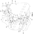
- a treatment device 122 comprising a device frame 124 containing a plurality of device head assemblies 200 arranged in columns and rows, and which are packed in close proximity to each other within the device frame 124.
- a treatment device 122 may include any number of columns and any number of rows of device head assemblies 200, including a single column and/or a single row.
- a gear system 132 is coupled to the lateral side 126 of the device frame 124 for actuation of the device frame 124 relative to an adjacent device frame 124 via one of the device actuation systems 130 ( Figure 7 ).
- the device head assembly 200 includes a head frame 202 and a pitch-yaw actuation system 230.
- the head frame 202 is generally hollow and has an orthogonal shape having a long depth relative to the length and width that define the cross-sectional shape of the head frame 202.
- the head frame 202 has a head frame upper portion 204 and a head frame lower portion 206.
- the pitch-yaw actuation system 230 is configured in a manner that capitalizes on the relatively long depth of the head frame 202, and allows for a relatively large number of device head assemblies 200 ( Figure 8 ) to be packed within a single device frame 124 ( Figure 8 ).
- the pitch-yaw actuation system 230 is mounted on the head frame upper portion 204.
- a device head 210 is supported by the pitch-yaw actuation system 230.
- the device head 210 is configured to dispense a treatment along a dispensing direction 128 ( Figure 8 ) of the device head 210.
- the device head 210 is an inkjet printhead 214 configured to dispense ink.
- the inkjet printhead 214 includes a pair of fluid conduits 216 for supplying and returning ink to and from the inkjet printhead 214.
- a flexible data cable 218 extends from the underside of the inkjet printhead 214 for controlling the operation of the inkjet printhead 214.
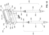
- the pitch-yaw actuation system 230 includes a pitch frame 232, a yaw frame 270, a pitch actuator 250, a yaw actuator 290, and a universal joint assembly 300.
- the pitch frame 232 is pivotably coupled to the device frame 124 via a pitch hinge 238. More specifically, the pitch hinge 238 pivotably couples the pitch frame 232 to the head frame 202, and the head frame 202 is mountable to (i.e., inside) the device frame 124 as shown in Figure 8 .
- the pitch hinge 238 has a pitch axis 240.
- the pitch frame 232 includes a pair of pitch frame tabs 234 interconnected by a pitch frame connecting member 236.
- the pitch frame tabs 234 are spaced apart from each other to define a pitch frame opening that is sized and configured to receive the device head 210.
- the pitch frame connecting member 236 is shaped in a manner to avoid interfering with the pivoting of the device head 210 about the yaw axis 282.
- the pitch hinge 238 is integrated into the pitch frame 232 and the device frame 124.
- the pitch hinge 238 includes a pitch hinge bore 244 formed in a head frame hinge post 208 extending upwardly from the head frame upper portion 204.
- a pitch hinge bore 244 is also formed in the pitch frame 232.
- a pitch hinge pin 242 extends through the pitch hinge bores 244 to thereby couple the pitch frame 232 to the head frame 202.
- the pitch-yaw actuation system 230 may include a pitch hinge 238 as a separate component coupling the pitch frame 232 to the head frame 202.
- the yaw frame 270 is pivotably coupled to the pitch frame 232 via a pair of yaw hinges 280 that define the yaw axis 282.
- the yaw frame 270 is made up of a yaw frame first portion 272 and a yaw frame second portion 274, which are separate members.
- the yaw frame first portion 272 and the yaw frame second portion 274 each have a yaw frame tab 278.
- the yaw frame first portion 272 has a yaw frame arm 276 which extends downwardly from the yaw frame tab 278.
- the yaw frame first portion 272 is pivotably coupled to the pitch frame tab 234 via a yaw hinge 280 on one side of the device head 210.
- the yaw frame second portion 274 is pivotably coupled to the pitch frame tab 234 via a yaw hinge 280 on an opposite side of the device head 210.
- Each yaw hinge 280 includes yaw hinge pin 284 that extends into a yaw hinge bore 286 formed in the yaw frame first portion 272 or yaw frame second portion 274.
- the pitch-yaw actuation system 230 is configured such that the yaw axis 282 ( Figures 10-13 ) is orthogonal to the pitch axis 240 ( Figures 10-13 ).
- the device head 210 includes a pair of device head mounting tabs 220 for attaching the device head 210 to the yaw frame tabs 278 respectively of the yaw frame first portion 272 and the yaw frame second portion 274.
- each pitch frame tab 234 has a pair of pivot stops 248 on opposite sides of the yaw axis 282.
- the pivot stops 248 are angled surfaces on the underside of each pitch frame tab 234.
- the upper surfaces of the yaw frame tabs 278 make contact with the pivot stops 248, thereby limiting the range of pivoting motion of the device head 210, and which may advantageously prevent the fluid conduits 216 ( Figure 14 ) and data cable 218 ( Figure 14 ) of the inkjet printhead 214 from contacting the inner sides of the head frame upper portion 204 during pivoting of the device head 210 about the yaw axis 282.
- the yaw hinges 280 are integrated into the yaw frame 270 and pitch frame 232.
- the yaw hinges 280 may be separate components from the yaw frame 270 and pitch frame 232.
- the yaw frame first portion 272 and the yaw frame second portion 274 may be interconnected by a yaw frame connecting member (not shown), which is preferably shaped in a manner to avoid interfering with pivoting of the device head 210 about the yaw axis 282.
- the pitch actuator 250 is configured to pivot the pitch frame 232 (and the device head 210) about the pitch axis 240.
- the pitch actuator 250 is configured as a linear actuator 260 having an actuator axis 258 ( Figure 12 ) extending along a depthwise direction of the head frame 202.
- the pitch actuator 250 is located on a pitch actuator side of the device head assembly 200.
- the actuator axis 258 of the pitch actuator 250 is oriented orthogonal to both the pitch axis 240 and the yaw axis 282.
- the yaw actuator 290 is configured to pivot the yaw frame 270 (and the device head 210) about the yaw axis 282.
- the yaw actuator 290 is configured as a linear actuator 260 similar to the pitch actuator 250.
- the yaw actuator 290 and the pitch actuator 250 are located on opposite sides of the head frame 202.
- the yaw actuator 290 has an actuator axis 258 oriented orthogonal to both the pitch axis 240 and the yaw axis 282.
- the actuator axis 258 of the yaw actuator 290 is generally parallel to the actuator axis 258 of the pitch actuator 250.
- the yaw actuator 290 has a yaw actuator fixed portion 292 and a yaw actuator extendable portion 294.
- the yaw actuator fixed portion 292 is fixedly couplable to the head frame 202.
- the yaw actuator 290 has a yaw actuator terminal end 296 that is coupled to the yaw frame arm 276 via the universal joint assembly 300, as described in greater detail below.
- the pitch actuator 250 and the yaw actuator 290 are each configured as an electric linear actuator 260 ( Figure 12 ) having a small servomotor (not shown) driving a ballscrew mechanism (not shown).
- the servomotor and the ballscrew mechanism are contained within a cylindrical housing 262 ( Figure 12 ).
- each electric linear actuator 260 has a pushrod 264 ( Figure 12 ) which is threadably engaged to the ballscrew mechanism, and which extends out of the housing 262.
- the housing 262 may be coupled to the head frame 202 via a gimbal mount (not shown).
- Rotation of the ballscrew mechanism via the servomotor causes axial motion of the pushrod 264 relative to the housing 262 for pivoting the device head 210 about the pitch axis 240 and yaw axis 282.
- the pitch actuator 250 and the yaw actuator 290 may optionally be configured as a pneumatic linear actuator.
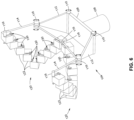
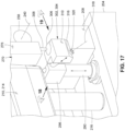
- the universal joint assembly 300 includes a linear guide mechanism 316 and a universal joint 302.
- the linear guide mechanism 316 has a guide mechanism axis 318.
- the universal joint 302 is slidably coupled to the linear guide mechanism 316.
- the guide mechanism axis 318 is oriented at an angle that allows the universal joint 302 to move along the linear guide mechanism 316 in a manner accommodating misalignment of the yaw actuator 290 with the yaw frame 270 during pivoting of the pitch frame 232 and/or yaw frame 270.
- the linear guide mechanism 316 is configured to allow the universal joint 302 to translate along the linear guide mechanism 316 while the universal joint 302 rotates.
- the universal joint assembly 300 allows simultaneous pivoting of the device head 210 about the pivot axis and the yaw axis 282.
- the universal joint 302 is a ball-and-socket joint 304.
- the ball-and-socket joint 304 includes a ball 306 having a spherical shape, and a joint body 310 having a socket 314 configured to receive the ball 306.
- the ball 306 is fixedly coupled to an end of the yaw frame arm 276 via a ball stud 308.
- the universal joint 302 may be provided in any one of a variety of alternative configurations that provide universal rotation capability.
- the universal joint 302 may be configured as a Hooke joint comprised of two yoke fittings interconnected by a cross-shaped member, with one of the yoke fittings slidably coupled to the linear guide mechanism 316, and the other yoke fitting fixedly coupled to the yaw frame arm 276.
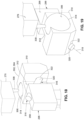
- the linear guide mechanism 316 is a guide pin 320 that is fixedly coupled to the yaw actuator terminal end 296.
- the joint body 310 includes a guide pin bore 322 that is sized and configured to slidably receive the guide pin 320.
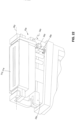
- the joint body 310 has a joint body side face 312 ( Figure 18 ) configured complementary to a terminal end side face 298 ( Figure 19 ) of the yaw actuator terminal end 296.
- the joint body side face 312 slides in close parallel (e.g., non-contacting) relation to the terminal end side face 298, thereby preventing rotation of the joint body 310 about the guide pin 320, which may otherwise complicate the dynamics for controlling yaw pivoting of the device head 210.
- the guide pin 320 may be fixedly coupled to the joint body 310, and the guide pin bore 322 may be formed in the yaw actuator terminal end 296.
- the ball 306 of the ball-and-socket joint 304 may be fixedly coupled to the yaw actuator terminal end 296, and the guide pin 320 may be coupled to the yaw frame 270.
- the guide pin 320 may be either fixedly coupled to the yaw frame arm 276 and slidable within a guide pin bore 322 in the joint body 310, or the guide pin 320 may be fixedly coupled to the joint body 310 and slidable within a guide pin bore 322 in the yaw frame arm 276.
- the guide mechanism axis 318 (e.g., the guide pin 320) is oriented at an angle that allows the universal joint 302 (e.g., the joint body 310) to move along the linear guide mechanism 316 in a manner accommodating misalignment of the yaw actuator 290 ( Figure 17 ) with the yaw frame 270 ( Figure 17 ) during pivoting of the pitch frame 232 ( Figure 16 ) and/or the yaw frame 270 ( Figure 16 ).
- the guide mechanism axis 318 is parallel to the pitch axis 240 when the pitch-yaw actuation system 230 is viewed along a direction parallel to the pitch axis 240.
- the guide mechanism axis 318 is oriented at an acute angle relative to the pitch axis 240 when the pitch-yaw actuation system 230 is viewed along a direction parallel to the yaw axis 282.
- the acute angle ⁇ of the guide mechanism axis 318 is approximately 45 degrees (e.g., ⁇ 20 degrees).
- the guide mechanism axis 318 may be oriented in any one of a variety of different directions that accommodates misalignment of the yaw actuator 290 with the yaw frame 270 during pivoting motion of the device head 210.
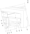
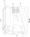
- the pitch-yaw actuation system 230 when the pitch-yaw actuation system 230 is viewed from the side, the universal joint assembly 300 is located below the pitch hinge 238, which is located below the yaw hinge 280.
- the pitch-yaw actuation system 230 may be configured such that the universal joint assembly 300 is located between the pitch hinge 238 and the yaw hinge 280 when the pitch-yaw actuation system 230 is viewed from the side.
- the above-mentioned pivot stops 248 incorporated into the pitch frame tabs 234 for limiting the range of pivoting motion of the device head 210 in either direction about the yaw axis 282.
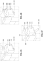
- Figures 21-27 shown are illustrations of the device head 210 prior to and during pivoting motion using the pitch-yaw actuation system 230.
- Figure 21 shows the device head 210 in a home position 212, prior to pivoting about the pitch axis 240 and yaw axis 282.
- Figure 25 is a magnified view of the universal joint assembly 300 showing the position of the joint body 310 on the guide pin 320 when the device head 210 is in the home position 212.
- the ball stud 308 has a generally vertical orientation.
- Figure 22 shows the pitch actuator 250 pivoting the device head 210 downwardly about the pitch axis 240
- Figure 23 shows the pitch actuator 250 pivoting the device head 210 upwardly about the pitch axis 240
- Figure 26 is a magnified view of the universal joint assembly 300 showing the rotation of the ball 306 within the joint body 310 of the universal joint 302 when the device head 210 is pivoted about the pitch axis 240. The rotation of the ball 306 is evident from the non-vertical orientation of the axis of the ball stud 308 in Figure 26 , relative to the vertical orientation of the ball stud 308 axis in Figure 25 .
- Figure 24 shows the yaw actuator 290 pivoting the device head 210 about the yaw axis 282 while the device head 210 remains pivoted about the pitch axis 240.
- Figure 27 is a magnified view of the universal joint assembly 300 showing slightly more rotation of the ball 306 within the joint body 310 as a result of the pivoting of the device head 210 about the yaw axis 282. Additionally, Figure 27 shows the universal joint 302 repositioned along the linear guide mechanism 316 as a result of the device head 210 pivoting about the yaw axis 282.
- the joint body side face 312 slides in close parallel relation to the terminal end side face 298 as the joint body 310 slides along the guide pin 320, thereby preventing rotation of the joint body 310 about the guide pin 320.
- the combination of the universal joint 302 and linear guide mechanism 316 allows for simultaneous pivoting motion and yawing motion of the device head 210, and thereby facilitates movement of the device head 210 within a wide range of motion.
- the pitch-yaw actuation system 230 is configured to fit within a relatively small footprint or cross-sectional area.
- the pitch-yaw actuation system 230 is configured such that the pitch frame 232, the yaw frame 270, the pitch actuator 250, the yaw actuator 290, and/or the universal joint assembly 300 are non-protruding from the cross-sectional perimeter of the head frame 202 when viewed along a direction parallel to the actuator axes 258.
- the small footprint of the pitch-yaw actuation system 230 allows for packing a large number of device head assemblies 200 within a single device frame 124 (e.g., see Figure 8 ).
- the small footprint is due in part to the orientation of the pitch actuator 250 and yaw actuator 290 parallel to the depthwise direction of the head frame 202.
- the use of linear actuators 260 i.e., the pitch actuator 250 and the yaw actuator 290 to provide the pivot-driving force, instead of more bulky rotary actuators, capitalizes on the relatively long depth of the head frame 202, and keeps the pivot-driving forces away from contamination-sensitive article surfaces 422 directly underneath the inkjet printhead 214.
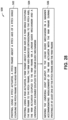
- FIG. 28 shown is a flowchart of operations included in a method 500 of actuating a device head 210 of a treatment device 122.
- a plurality of device heads 210 are supported in close proximity to each other within a device frame 124 of each treatment device 122.
- Figures 1-3 show arrays 120 of treatment devices 122 being moved along a fuselage 426 for treating the fuselage surfaces.
- Step 502 of the method 500 comprises pivoting, using a pitch actuator 250, a pitch frame 232 about a pitch axis 240 of a pitch hinge 238 coupling the pitch frame 232 to a head frame 202.
- the pitch frame 232 is coupled to the head frame hinge post 208, which protrudes upwardly from the head frame 202.
- step 502 of pivoting the pitch frame 232 about the pitch axis 240 comprises pivoting the pitch frame 232 about the pitch axis 240 of the pitch hinge 238 integrated into one side of the pitch frame 232.
- a pitch hinge pin 242 extends through the pitch hinge bores 244 respectively formed in the head frame hinge post 208 and the pitch frame 232, to thereby couple the pitch frame 232 to the head frame 202.
- Step 504 of the method 500 comprises pivoting, using a yaw actuator 290, a yaw frame 270 about a yaw axis 282 of a yaw hinge 280 coupling the yaw frame 270 to the pitch frame 232.
- the yaw axis 282 is oriented orthogonal to the pitch axis 240.
- the yaw actuator 290 is coupled to the yaw frame 270 via a universal joint assembly 300.
- the universal joint assembly 300 includes a linear guide mechanism 316 and a universal joint 302 slidably coupled to the linear guide mechanism 316.
- step 504 of pivoting the yaw frame 270 about the yaw axis 282 comprises pivoting the yaw frame 270 about the yaw axis 282 of the yaw hinges 280 integrated into the pitch frame 232 and the yaw frame 270.
- step 504 includes pivoting the yaw frame 270 about the yaw axis 282 defined by a pair of yaw hinges 280 respectively on opposite sides of the pitch frame 232.
- a yaw hinge pin 284 extends into a yaw hinge bore 286 formed in either the yaw frame first portion 272 or yaw frame second portion 274.
- step 502 of pivoting the pitch frame 232 is performed via the pitch actuator 250 configured as a linear actuator 260.
- step 502 of pivoting the pitch frame 232 is performed by a linear actuator 260 configured as an electric linear actuator 260 having a ballscrew mechanism (not shown) and a pushrod 264 threadably engaged to the ballscrew mechanism for axially moving the pushrod 264.
- step 504 of pivoting the yaw frame 270 is performed via the yaw actuator 290 configured as a linear actuator 260, which may also be configured as an electric linear actuator 260 similar to the above-described pitch actuator 250.
- step 502 of pivoting the pitch frame 232 and step 504 of pivoting the yaw frame 270 are respectively performed by the pitch actuator 250 and the yaw actuator 290 located on opposite sides of the device head 210.
- step 502 of pivoting the pitch frame 232 is performed by the pitch actuator 250 actuating along an actuator axis 258 oriented orthogonal to both the pitch axis 240 and the yaw axis 282.
- step 504 of pivoting the yaw frame 270 is performed by the yaw actuator 20 actuating along an actuator axis 258 oriented orthogonal to both the pitch axis 240 and the yaw axis 282.
- Step 502 of pivoting the pitch frame 232 about the pitch axis 240 includes pivoting the pitch frame 232 about the pitch axis 240 located between the yaw axis 282 and the universal joint assembly 300, as shown in Figure 20 .
- the universal joint assembly 300 may be located between the pitch axis 240 and the yaw axis 282
- translating the universal joint 302 along the linear guide mechanism 316 includes translating the universal joint 302 along the guide mechanism axis 318 oriented at an acute angle relative to the pitch axis 240 when the head frame 202 is viewed along a direction parallel to the yaw axis 282.
- the universal joint 302 is translated along the guide mechanism axis 318 oriented at an angle of approximately 45 degrees.
- step 506 of moving the universal joint 302 relative to the linear guide mechanism 316 comprises sliding a guide pin 320 within a guide pin bore 322.
- the guide pin 320 is fixedly coupled to the yaw actuator terminal end 296, and the guide pin 320 slides within a guide pin bore 322 in the joint body 310.
- the guide pin 320 may be fixedly coupled to the joint body 310, and the guide pin 320 slides within a guide pin bore 322 formed in the yaw actuator terminal end 296.
- step 506 of moving the universal joint 302 relative to the linear guide mechanism 316 includes rotating the ball 306 within the socket 314 formed in the joint body 310 of the ball-and-socket joint 304.
- the ball 306 rotates within the socket 314 during pivoting of the device head 210 about the pitch axis 240 and/or during pivoting of the device head 210 at about the yaw axis 282.
- the method 500 further includes discharging a treatment from a device head 210 supported by the pitch frame 232 and the yaw frame 270.
- the treatment is discharged from the device head 210 prior to, during, and/or after pivoting of the device head 210 about the pitch axis 240 and/or yaw axis 282.
- the device head 210 is configured to dispense the treatment along a dispensing direction 128 toward an article surface 422 of an article 420, such as for applying a livery to an aircraft fuselage.
- a pitch-yaw actuation system for actuating a device head, comprising: a pitch frame configured to be pivotably coupled to a device frame via a pitch hinge having a pitch axis; a yaw frame pivotably coupled to the pitch frame via a yaw hinge having a yaw axis orthogonal to the pitch axis; a pitch actuator configured to pivot the pitch frame about the pitch axis; a yaw actuator configured to pivot the yaw frame about the yaw axis; a universal joint assembly coupling the yaw actuator to the yaw frame, and including: a linear guide mechanism having a guide mechanism axis; a universal joint slidably coupled to the linear guide mechanism; and the guide mechanism axis is oriented at an angle that allows the universal joint to move in a manner accommodating misalignment of the yaw actuator with the yaw frame during pivoting of at least one of the pitch frame and
- At least one of the pitch actuator and the yaw actuator is a linear actuator.
- the linear actuator is an electric linear actuator having a ballscrew mechanism and a push rod threadably engaged to the ballscrew mechanism for axially moving the push rod.
- the yaw actuator and the pitch actuator are located on opposite sides of the yaw frame.
- the pitch actuator and the yaw actuator each have an actuator axis oriented orthogonal to both the pitch axis and the yaw axis.
- the pitch axis is located between the yaw axis and the universal joint.
- the linear guide mechanism is configured to allow the universal joint to translate along the linear guide mechanism while simultaneously rotating about the guide mechanism axis.
- the guide mechanism axis is oriented at an acute angle relative to the pitch axis when the pitch-yaw actuation system is viewed along a direction parallel to the yaw axis.
- the acute angle of the guide mechanism axis is approximately 45 degrees.
- the linear guide mechanism comprises a guide pin, and a guide pin bore configured to slidably receive the guide pin.
- the pitch hinge is integrated into a common side of the pitch frame and the yaw frame.
- the yaw frame is configured to receive a device head configured to discharge a treatment.
- the yaw frame has a yaw frame opening configured to receive the device head
- the pitch-yaw actuation system includes a pair of yaw hinges respectively on opposite sides of the pitch frame.
- a device head assembly comprising: a head frame; a pitch-yaw actuation system, including: a pitch frame coupled to the head frame via a pitch hinge having a pitch axis; a yaw frame coupled to the pitch frame via a yaw hinge having a yaw axis orthogonal to the pitch axis, the yaw frame configured to receive a device head; a pitch actuator coupled to the head frame and configured to pivot the pitch frame about the pitch axis; a yaw actuator coupled to the head frame and configured to pivot the yaw frame about the yaw axis; a universal joint assembly configured to couple the yaw actuator to the yaw frame, and including: a linear guide mechanism having a guide mechanism axis; a universal joint slidably couplable to the linear guide mechanism; and the guide mechanism axis is oriented at an angle allowing the universal joint to move relative to the linear guide mechanism in a manner accommodating misalignment of the
- the head frame has a head frame cross-sectional perimeter; and at least one of the pitch frame, the yaw frame, the pitch actuator, the yaw actuator, and the universal joint assembly are configured to be non-protruding from the head frame cross-sectional perimeter when the head frame is viewed along a direction parallel to an actuator axis of the pitch actuator and the yaw actuator.
- the pitch hinge is integrated into the pitch frame and the head frame; and the yaw hinge is integrated into the yaw frame and the pitch frame.
- At least one of the pitch actuator and the yaw actuator is a linear actuator (260).
- the linear actuator is an electric linear actuator having a ballscrew mechanism and a push rod threadably engaged to the ballscrew mechanism for axially moving the push rod.
- the yaw actuator and the pitch actuator are located on opposite sides of the yaw frame.
- the pitch actuator and the yaw actuator each have an actuator axis oriented orthogonal to both the pitch axis and the yaw axis.
- the pitch axis is located between the yaw axis and the universal joint.
- the linear guide mechanism is configured to allow the universal joint to translate along the linear guide mechanism while simultaneously rotating about the guide mechanism axis.
- the guide mechanism axis is oriented at an acute angle relative to the pitch axis when the head frame is viewed along a direction parallel to the yaw axis; and the guide mechanism axis is parallel to the pitch axis when the head frame is viewed along a direction parallel to the pitch axis.
- the acute angle of the guide mechanism axis is approximately 45 degrees.
- the universal joint is a ball -and-socket joint having a ball, and a joint body having a socket configured to receive the ball.
- the linear guide mechanism comprises a guide pin, and a guide pin bore configured to slidably receive the guide pin.
- the yaw actuator has a yaw actuator terminal end; the universal joint has a joint body; the guide pin is fixedly coupled to the yaw actuator terminal end; and the guide pin bore is formed in the joint body.
- the pitch hinge is integrated into a common side of the pitch frame and the yaw frame.
- the yaw frame has a yaw frame opening configured to receive the device head
- the pitch-yaw actuation system includes a pair of yaw hinges respectively on opposite sides of the pitch frame.
- a method of actuating a device head comprising: pivoting, using a pitch actuator, a pitch frame about a pitch axis of a pitch hinge coupling the pitch frame to a head frame; pivoting, using a yaw actuator, a yaw frame about a yaw axis of a yaw hinge coupling the yaw frame to the pitch frame, the yaw axis oriented orthogonal to the pitch axis, the yaw actuator coupled to the yaw frame via a linear guide mechanism and a universal joint slidably coupled to the linear guide mechanism; and moving the universal joint relative to the linear guide mechanism in a manner accommodating misalignment of the yaw actuator with the yaw frame during pivoting of at least one of the pitch frame and the yaw frame.
- At least one of pivoting the pitch frame and pivoting the yaw frame are respectively performed by the pitch actuator and the yaw actuator, each configured as a linear actuator.
- At least one of pivoting the pitch frame and pivoting the yaw frame is respectively performed by an electric linear actuator.
- pivoting the pitch frame and pivoting the yaw frame are respectively performed by the pitch actuator and the yaw actuator located on opposite sides of the pitch frame.
- pivoting the pitch frame and pivoting the yaw frame are respectively performed by the pitch actuator and the yaw actuator each actuating along an actuator axis oriented orthogonal to both the pitch axis and the yaw axis.
- pivoting the pitch frame about the pitch axis comprises: pivoting the pitch frame about the pitch axis located between the yaw axis and the universal joint.
- translating the universal joint along the linear guide mechanism comprises: translating the universal joint along a guide mechanism axis oriented at an acute angle relative to the pitch axis when the head frame is viewed along a direction parallel to the yaw axis.
- translating the universal joint along the guide mechanism axis oriented at the acute angle comprises: translating the universal joint along the guide mechanism axis oriented at an angle of approximately 45 degrees.
- moving the universal joint relative to the linear guide mechanism comprises: rotating a ball within a socket formed in a joint body of a ball -and-socket joint.
- moving the universal joint relative to the linear guide mechanism comprises: sliding a guide pin within a guide pin bore.
- sliding the guide pin within the guide pin bore comprises: sliding the guide pin within the guide pin bore formed in a j oint body of the universal j oint, the guide pin fixedly coupled to a yaw actuator terminal end of the yaw actuator.
- pivoting the pitch frame about the pitch axis comprises: pivoting the pitch frame about the pitch axis of the pitch hinge integrated into one side of the pitch frame.
- pivoting the yaw frame about the yaw axis comprises: pivoting the yaw frame about the yaw axis defined by a pair of yaw hinges respectively on opposite sides of pitch frame.
- the method further comprises: discharging a treatment from a device head supported by the pitch frame and the yaw frame.
Landscapes
- Engineering & Computer Science (AREA)
- Manufacturing & Machinery (AREA)
- Transportation (AREA)
- Aviation & Aerospace Engineering (AREA)
- Transmission Devices (AREA)
- Spray Control Apparatus (AREA)
- Coating Apparatus (AREA)
Claims (15)
- Nick- und Gierbetätigungssystem (230) zum Betätigen eines Vorrichtungskopfes (210), das aufweist:einen Nickrahmen (232), der eingerichtet ist, schwenkbar an einen Vorrichtungsrahmen (124) über ein Nickscharnier (238), das eine Nickachse (240) aufweist, gekoppelt zu werden;einen Gierrahmen (270), der schwenkbar an den Nickrahmen (232) über ein Gierscharnier (280), das eine Gierachse (282) orthogonal zur Nickachse (240) aufweist, gekoppelt ist;einen Nickaktuator (250), der eingerichtet ist, den Nickrahmen (232) und die Nickachse (240) zu schwenken;einen Gieraktuator (290), der eingerichtet ist, den Gierrahmen (270) um die Gierachse (282) zu schwenken;eine Universalgelenkanordnung (300), die den Gieraktuator (290) an den Gierrahmen (270) koppelt und die umfasst:einen linearen Führungsmechanismus (316) mit einer Führungsmechanismusachse (318);ein Universalgelenk (302), das gleitend an den linearen Führungsmechanismus (316) gekoppelt ist; undwobei die Führungsmechanismusachse (318) in einem Winkel orientiert ist, der es dem Universalgelenk (302) ermöglicht, sich in einer Weise zu bewegen, die eine Fehlausrichtung des Gieraktuators (290) mit dem Gierrahmen (270) während eines Schwenkens des Nickrahmens (232) und/oder des Gierrahmens (270) ausgleicht.
- Nick- und Gierbetätigungssystem (230) nach Anspruch 1, wobei:
der Gieraktuator (290) und der Nickaktuator (250) auf gegenüberliegenden Seiten des Gierrahmens (270) lokalisiert sind. - Nick- und Gierbetätigungssystem (230) nach Anspruch 1 oder 2, wobei:
der Nickaktuator (250) und der Gieraktuator (290) jeweils eine Aktuatorachse (258) aufweisen, die orthogonal sowohl zur Nickachse (240) als auch zur Gierachse (282) orientiert ist. - Nick- und Gierbetätigungssystem (230) nach einem der Ansprüche 1 bis 3, wobei:
die Nickachse (240) zwischen der Gierachse (282) und dem Universalgelenk (302) lokalisiert ist. - Nick- und Gierbetätigungssystem (230) nach einem der Ansprüche 1 bis 4, wobei:
der lineare Führungsmechanismus (316) eingerichtet ist, es dem Universalgelenk (302) zu ermöglichen, sich entlang des linearen Führungsmechanismus (316) zu verschieben, während es sich gleichzeitig um die Führungsmechanismusachse (318) dreht. - Nick- und Gierbetätigungssystem (230) nach einem der Ansprüche 1 bis 5, wobei:
die Führungsmechanismusachse (318) in einem spitzen Winkel relativ zur Nickachse (240) orientiert ist, wenn das Nick- und Gierbetätigungssystem (230) entlang einer Richtung parallel zur Gierachse (282) betrachtet wird. - Nick- und Gierbetätigungssystem (230) nach einem der Ansprüche 1 bis 6, wobei:der lineare Führungsmechanismus (316) einen Führungsstift (320) und eine Führungsstiftbohrung (322) aufweist, die eingerichtet ist, den Führungsstift (320) gleitend aufzunehmen;der Gieraktuator (290) ein Gieraktuatorabschlussende (296) aufweist;das Universalgelenk (302) einen Gelenkkörper (310) aufweist;der Führungsstift (320) fest an das Gieraktuatorabschlussende (296) gekoppelt ist; unddie Führungsstiftbohrung (322) im Gelenkkörper (310) ausgebildet ist.
- Nick- und Gierbetätigungssystem (230) nach einem der Ansprüche 1 bis 7, wobei:der Gierrahmen (270) eingerichtet ist, einen Vorrichtungskopf (210) aufzunehmen, der zum Auslassen einer Behandlung eingerichtet ist; undder Gierrahmen (270) eine Gierrahmenöffnung aufweist, die eingerichtet ist, den Vorrichtungskopf (210) aufzunehmen, wobei das Nick- und Gierbetätigungssystem (230) ein Paar von Gierscharnieren (280) auf jeweils gegenüberliegenden Seiten des Nickrahmens (232) umfasst.
- Verfahren zum Betätigen eines Vorrichtungskopfes (210), das aufweist:Schwenken, unter Verwendung eines Nickaktuators (250), eines Nickrahmens (232) um eine Nickachse (240) eines Nickscharniers (238), das den Nickrahmen (232) an einen Kopfrahmen (202) koppelt;Schwenken, unter Verwendung eines Gieraktuators (290), eines Gierrahmens (270) um eine Gierachse (282) eines Gierscharniers (280), das den Gierrahmen (270) an den Nickrahmen (232) koppelt, wobei die Gierachse (282) orthogonal zur Nickachse (240) orientiert ist, wobei der Gieraktuator (290) an den Gierrahmen (270) über einen linearen Führungsmechanismus (316) und ein Universalgelenk (302) gekoppelt ist, das gleitend an den linearen Führungsmechanismus (316) gekoppelt ist; undBewegen des Universalgelenks (302) relativ zum linearen Führungsmechanismus (316) auf eine Weise, die eine Fehlausrichtung des Gieraktuators (290) mit dem Gierrahmen (270) während eines Schwenkens des Nickrahmens (232) und/oder des Gierrahmens (270) ausgleicht.
- Verfahren nach Anspruch 9, wobei ein Schwenken des Nickrahmens (232) um die Nickachse (240) aufweist:
Schwenken des Nickrahmens (232) um die Nickachse (240), die zwischen der Gierachse (282) und dem Universalgelenk (302) lokalisiert ist. - Verfahren nach Anspruch 9 oder 10, wobei ein Verschieben des Universalgelenks (302) entlang des linearen Führungsmechanismus (316) aufweist:
Verschieben des Universalgelenks (302) entlang einer Führungsmechanismusachse (318), die in einem spitzen Winkel relativ zur Nickachse (240) orientiert ist, wenn der Kopfrahmen (202) entlang einer Richtung parallel zur Gierachse (282) betrachtet wird. - Verfahren nach einem der Ansprüche 9 bis 11, wobei ein Bewegen des Universalgelenks (302) relativ zum linearen Führungsmechanismus (316) aufweist:
Verschieben eines Führungsstifts (320) in einer Führungsstiftbohrung (322), die in einem Gelenkkörper (310) des Universalgelenks (302) ausgebildet ist, wobei der Führungsstift (320) fest an ein Gieraktuatorabschlussende (296) des Gieraktuators (290) gekoppelt ist. - Verfahren nach einem der Ansprüche 9 bis 12, wobei ein Schwenken des Nickrahmens (232) um die Nickachse (240) aufweist:
Schwenken des Nickrahmens (232) um die Nickachse (240) des Nickscharniers (238), das in eine Seite des Nickrahmens (232) integriert ist. - Verfahren nach einem der Ansprüche 9 bis 13, wobei ein Schwenken des Gierrahmens (270) um die Gierachse (282) aufweist:
Schwenken des Gierrahmens (290) um die Gierachse (282), die durch ein Paar von Gierscharnieren (280) jeweils auf gegenüberliegenden Seiten eines Nickrahmens (232) definiert ist. - Verfahren nach einem der Ansprüche 9 bis 14, das ferner aufweist:
Auslassen einer Behandlung aus einem Vorrichtungskopf (210), der durch den Nickrahmen (232) und den Gierrahmen (270) gehalten wird.
Applications Claiming Priority (1)
| Application Number | Priority Date | Filing Date | Title |
|---|---|---|---|
| US202163202244P | 2021-06-02 | 2021-06-02 |
Publications (2)
| Publication Number | Publication Date |
|---|---|
| EP4098371A1 EP4098371A1 (de) | 2022-12-07 |
| EP4098371B1 true EP4098371B1 (de) | 2024-09-18 |
Family
ID=81386642
Family Applications (1)
| Application Number | Title | Priority Date | Filing Date |
|---|---|---|---|
| EP22169755.0A Active EP4098371B1 (de) | 2021-06-02 | 2022-04-25 | Nick- und giersystem und verfahren zur betätigung eines vorrichtungskopfs |
Country Status (4)
| Country | Link |
|---|---|
| US (1) | US12017801B2 (de) |
| EP (1) | EP4098371B1 (de) |
| JP (1) | JP2022185565A (de) |
| CN (1) | CN115489750A (de) |
Families Citing this family (3)
| Publication number | Priority date | Publication date | Assignee | Title |
|---|---|---|---|---|
| DE102022108851A1 (de) * | 2022-04-12 | 2023-10-12 | Homag Gmbh | Druckvorrichtung sowie Verfahren zum Bedrucken eines Werkstücks |
| US12344010B2 (en) * | 2022-12-22 | 2025-07-01 | The Boeing Company | Multi-printhead end effector and associated system and method |
| CN121263312A (zh) * | 2023-06-23 | 2026-01-02 | 艾仕得涂料系统有限责任公司 | 涂层施加系统和涂覆基材的方法 |
Family Cites Families (34)
| Publication number | Priority date | Publication date | Assignee | Title |
|---|---|---|---|---|
| JPS58126090A (ja) * | 1982-01-18 | 1983-07-27 | 株式会社神戸製鋼所 | 多関節腕機構 |
| EP0455371A3 (en) | 1990-04-24 | 1992-04-22 | Engineering Incorporated | Robotic carrier mechanism for aircraft maintenance |
| GB9609379D0 (en) * | 1996-05-03 | 1996-07-10 | Willett Int Ltd | Mechanism and method |
| US6955229B1 (en) * | 2003-07-18 | 2005-10-18 | Hoffart Ronald J | Implement pitch-yaw system |
| US20050194155A1 (en) * | 2003-12-10 | 2005-09-08 | Dommert Karl R. | Blade pitch control structure for bulldozer |
| US7350890B2 (en) | 2004-08-26 | 2008-04-01 | The Boeing Company | Apparatus and methods for applying images to a surface |
| US8377852B2 (en) | 2007-10-26 | 2013-02-19 | Dow Corning Corporation | Method of preparing a substrate with a composition including an organoborane initiator |
| DE102009004878A1 (de) | 2009-01-16 | 2010-07-29 | Bauer, Jörg R. | Verfahren zum Beschichten, insbesondere Lackieren, einer Oberfläche sowie digitales Beschichtungssystem |
| US8088450B2 (en) * | 2009-03-13 | 2012-01-03 | The Boeing Company | Automated wing painting system |
| JP2013146989A (ja) | 2012-01-23 | 2013-08-01 | Seiko Precision Inc | 印字装置 |
| DE102012017538A1 (de) | 2012-09-05 | 2014-03-06 | Heidelberger Druckmaschinen Ag | Verfahren zum Bebildern und/oder Lackieren der Oberfläche von Gegenständen |
| EP2740563B1 (de) | 2012-12-05 | 2018-04-04 | TRUMPF Werkzeugmaschinen GmbH & Co. KG | Bearbeitungseinrichtung, Bearbeitungsmaschine und Verfahren zum Bewegen eines Bearbeitungskopfs |
| JP6198499B2 (ja) | 2013-07-04 | 2017-09-20 | 株式会社エルエーシー | プリント装置 |
| US10308039B2 (en) | 2015-05-29 | 2019-06-04 | The Boeing Company | System for printing images on a surface and method thereof |
| US9452616B1 (en) * | 2015-05-29 | 2016-09-27 | The Boeing Company | System and method for printing an image on a surface |
| US10144183B2 (en) | 2016-05-27 | 2018-12-04 | The Boeing Company | Verification of tow placement by a robot |
| US9961783B2 (en) * | 2016-07-08 | 2018-05-01 | Kateeva, Inc. | Guided transport path correction |
| JP2018035881A (ja) | 2016-08-31 | 2018-03-08 | ブラザー工業株式会社 | 回動直線駆動装置 |
| US10220408B2 (en) * | 2016-09-12 | 2019-03-05 | The Boeing Company | Variable radius print head end effector |
| US10384482B2 (en) | 2016-10-06 | 2019-08-20 | The Boeing Company | Actuated print head assembly for a contoured surface |
| US10369679B2 (en) * | 2016-11-09 | 2019-08-06 | The Boeing Company | Apparatus, system and method for performing automated finishing operations on a workpiece |
| US10307788B2 (en) | 2016-11-09 | 2019-06-04 | The Boeing Company | Integrated automation of paint processes incorporating arrayed painting and inkjet printing |
| US10875045B2 (en) * | 2016-12-16 | 2020-12-29 | The Boeing Company | Variable cross-section compliance mechanism |
| US10435181B2 (en) * | 2016-12-19 | 2019-10-08 | Embraer S.A. | Method for applying a treatment fluid to interior surfaces of an aircraft fuselage |
| US10384217B2 (en) | 2017-01-24 | 2019-08-20 | The Boeing Company | Adjustable cantilevered paint actuation system |
| US10745251B2 (en) | 2017-01-27 | 2020-08-18 | The Boeing Company | Belt drive dual robot gantry |
| US10814480B2 (en) * | 2017-06-14 | 2020-10-27 | The Boeing Company | Stabilization of tool-carrying end of extended-reach arm of automated apparatus |
| US10501208B2 (en) * | 2017-06-30 | 2019-12-10 | The Boeing Company | Gantry system and method for processing an aircraft |
| US10293601B2 (en) | 2017-07-11 | 2019-05-21 | The Boeing Company | Automated controls for contoured surface inkjet printing |
| US10532561B2 (en) | 2017-07-11 | 2020-01-14 | The Boeing Company | Metrology-based path planning for inkjet printing along a contoured surface |
| US10668738B1 (en) * | 2018-12-19 | 2020-06-02 | The Boeing Company | Inkjet printed livery application process |
| US11407166B2 (en) | 2019-09-30 | 2022-08-09 | The Boeing Company | Robotic 3D geometry direct-to-surface inkjet printing calibration process |
| US11595549B2 (en) | 2020-04-22 | 2023-02-28 | The Boeing Company | Aircraft inkjet printing |
| US11472678B2 (en) * | 2020-06-16 | 2022-10-18 | The Boeing Company | Gantry system and method |
-
2022
- 2022-04-21 JP JP2022070049A patent/JP2022185565A/ja active Pending
- 2022-04-23 US US17/660,405 patent/US12017801B2/en active Active
- 2022-04-25 EP EP22169755.0A patent/EP4098371B1/de active Active
- 2022-05-31 CN CN202210612031.7A patent/CN115489750A/zh active Pending
Also Published As
| Publication number | Publication date |
|---|---|
| US20220388685A1 (en) | 2022-12-08 |
| EP4098371A1 (de) | 2022-12-07 |
| US12017801B2 (en) | 2024-06-25 |
| CN115489750A (zh) | 2022-12-20 |
| JP2022185565A (ja) | 2022-12-14 |
Similar Documents
| Publication | Publication Date | Title |
|---|---|---|
| EP4098371B1 (de) | Nick- und giersystem und verfahren zur betätigung eines vorrichtungskopfs | |
| EP2554337B1 (de) | Roboter mit teleskopischen Vorrichtungen mit Gewindespindeln zur Positionierung eines Werkzeuges | |
| EP3628501B1 (de) | Verfahren zum drucken eines bildes auf einer oberfläche | |
| US8356571B2 (en) | Applicator and application method for applying a sealant to a flanged seam | |
| JP7001399B2 (ja) | 輪郭付けられた面のための駆動式印刷ヘッドアセンブリ | |
| US4905913A (en) | Contour following apparatus for positioning spray guns | |
| CN101426587A (zh) | 涂装系统 | |
| EP3335800B1 (de) | Tragkonstruktionsanordnung zur oberflächenbehandlung und verfahren | |
| US5656085A (en) | Paint spray apparatus with remote pump drive | |
| US12589510B2 (en) | Work device | |
| CN114430724A (zh) | 接地式载具 | |
| EP4098372B1 (de) | System und verfahren zum betätigen einer behandlungsvorrichtung | |
| US20250066038A1 (en) | System and method for a manufacturing environment with robotic system mounts having one or more end effectors positioned sympathetic to the underlying manufactured item | |
| EP4344887B1 (de) | Robotik zum tintenstrahldrucken eines fahrzeuglogos | |
| JP4575280B2 (ja) | 塗装システム | |
| EP4389432B1 (de) | Endeffektor mit mehreren druckköpfen und entsprechendes verfahren | |
| US20260042305A1 (en) | Multi-printhead end effector and associated system and method | |
| WO2025134362A1 (ja) | インクジェット塗布方法及びインクジェット塗布システム |
Legal Events
| Date | Code | Title | Description |
|---|---|---|---|
| PUAI | Public reference made under article 153(3) epc to a published international application that has entered the european phase |
Free format text: ORIGINAL CODE: 0009012 |
|
| STAA | Information on the status of an ep patent application or granted ep patent |
Free format text: STATUS: THE APPLICATION HAS BEEN PUBLISHED |
|
| AK | Designated contracting states |
Kind code of ref document: A1 Designated state(s): AL AT BE BG CH CY CZ DE DK EE ES FI FR GB GR HR HU IE IS IT LI LT LU LV MC MK MT NL NO PL PT RO RS SE SI SK SM TR |
|
| RAP3 | Party data changed (applicant data changed or rights of an application transferred) |
Owner name: THE BOEING COMPANY |
|
| STAA | Information on the status of an ep patent application or granted ep patent |
Free format text: STATUS: REQUEST FOR EXAMINATION WAS MADE |
|
| 17P | Request for examination filed |
Effective date: 20230413 |
|
| RBV | Designated contracting states (corrected) |
Designated state(s): AL AT BE BG CH CY CZ DE DK EE ES FI FR GB GR HR HU IE IS IT LI LT LU LV MC MK MT NL NO PL PT RO RS SE SI SK SM TR |
|
| GRAP | Despatch of communication of intention to grant a patent |
Free format text: ORIGINAL CODE: EPIDOSNIGR1 |
|
| STAA | Information on the status of an ep patent application or granted ep patent |
Free format text: STATUS: GRANT OF PATENT IS INTENDED |
|
| RIC1 | Information provided on ipc code assigned before grant |
Ipc: B05B 12/12 20060101ALN20240416BHEP Ipc: B64F 5/10 20170101ALI20240416BHEP Ipc: B41J 25/316 20060101ALI20240416BHEP Ipc: B41J 3/407 20060101ALI20240416BHEP Ipc: B05B 15/654 20180101ALI20240416BHEP Ipc: B05B 15/68 20180101ALI20240416BHEP Ipc: B05B 13/02 20060101ALI20240416BHEP Ipc: B05B 13/04 20060101AFI20240416BHEP |
|
| INTG | Intention to grant announced |
Effective date: 20240503 |
|
| P01 | Opt-out of the competence of the unified patent court (upc) registered |
Effective date: 20240524 |
|
| GRAS | Grant fee paid |
Free format text: ORIGINAL CODE: EPIDOSNIGR3 |
|
| GRAA | (expected) grant |
Free format text: ORIGINAL CODE: 0009210 |
|
| STAA | Information on the status of an ep patent application or granted ep patent |
Free format text: STATUS: THE PATENT HAS BEEN GRANTED |
|
| AK | Designated contracting states |
Kind code of ref document: B1 Designated state(s): AL AT BE BG CH CY CZ DE DK EE ES FI FR GB GR HR HU IE IS IT LI LT LU LV MC MK MT NL NO PL PT RO RS SE SI SK SM TR |
|
| REG | Reference to a national code |
Ref country code: GB Ref legal event code: FG4D |
|
| REG | Reference to a national code |
Ref country code: CH Ref legal event code: EP |
|
| REG | Reference to a national code |
Ref country code: DE Ref legal event code: R096 Ref document number: 602022006129 Country of ref document: DE |
|
| REG | Reference to a national code |
Ref country code: IE Ref legal event code: FG4D |
|
| REG | Reference to a national code |
Ref country code: LT Ref legal event code: MG9D |
|
| PG25 | Lapsed in a contracting state [announced via postgrant information from national office to epo] |
Ref country code: NO Free format text: LAPSE BECAUSE OF FAILURE TO SUBMIT A TRANSLATION OF THE DESCRIPTION OR TO PAY THE FEE WITHIN THE PRESCRIBED TIME-LIMIT Effective date: 20241218 |
|
| PG25 | Lapsed in a contracting state [announced via postgrant information from national office to epo] |
Ref country code: GR Free format text: LAPSE BECAUSE OF FAILURE TO SUBMIT A TRANSLATION OF THE DESCRIPTION OR TO PAY THE FEE WITHIN THE PRESCRIBED TIME-LIMIT Effective date: 20241219 Ref country code: FI Free format text: LAPSE BECAUSE OF FAILURE TO SUBMIT A TRANSLATION OF THE DESCRIPTION OR TO PAY THE FEE WITHIN THE PRESCRIBED TIME-LIMIT Effective date: 20240918 |
|
| PG25 | Lapsed in a contracting state [announced via postgrant information from national office to epo] |
Ref country code: BG Free format text: LAPSE BECAUSE OF FAILURE TO SUBMIT A TRANSLATION OF THE DESCRIPTION OR TO PAY THE FEE WITHIN THE PRESCRIBED TIME-LIMIT Effective date: 20240918 |
|
| PG25 | Lapsed in a contracting state [announced via postgrant information from national office to epo] |
Ref country code: LV Free format text: LAPSE BECAUSE OF FAILURE TO SUBMIT A TRANSLATION OF THE DESCRIPTION OR TO PAY THE FEE WITHIN THE PRESCRIBED TIME-LIMIT Effective date: 20240918 |
|
| PG25 | Lapsed in a contracting state [announced via postgrant information from national office to epo] |
Ref country code: HR Free format text: LAPSE BECAUSE OF FAILURE TO SUBMIT A TRANSLATION OF THE DESCRIPTION OR TO PAY THE FEE WITHIN THE PRESCRIBED TIME-LIMIT Effective date: 20240918 |
|
| REG | Reference to a national code |
Ref country code: NL Ref legal event code: MP Effective date: 20240918 |
|
| PG25 | Lapsed in a contracting state [announced via postgrant information from national office to epo] |
Ref country code: RS Free format text: LAPSE BECAUSE OF FAILURE TO SUBMIT A TRANSLATION OF THE DESCRIPTION OR TO PAY THE FEE WITHIN THE PRESCRIBED TIME-LIMIT Effective date: 20241218 |
|
| PG25 | Lapsed in a contracting state [announced via postgrant information from national office to epo] |
Ref country code: RS Free format text: LAPSE BECAUSE OF FAILURE TO SUBMIT A TRANSLATION OF THE DESCRIPTION OR TO PAY THE FEE WITHIN THE PRESCRIBED TIME-LIMIT Effective date: 20241218 Ref country code: NO Free format text: LAPSE BECAUSE OF FAILURE TO SUBMIT A TRANSLATION OF THE DESCRIPTION OR TO PAY THE FEE WITHIN THE PRESCRIBED TIME-LIMIT Effective date: 20241218 Ref country code: LV Free format text: LAPSE BECAUSE OF FAILURE TO SUBMIT A TRANSLATION OF THE DESCRIPTION OR TO PAY THE FEE WITHIN THE PRESCRIBED TIME-LIMIT Effective date: 20240918 Ref country code: HR Free format text: LAPSE BECAUSE OF FAILURE TO SUBMIT A TRANSLATION OF THE DESCRIPTION OR TO PAY THE FEE WITHIN THE PRESCRIBED TIME-LIMIT Effective date: 20240918 Ref country code: GR Free format text: LAPSE BECAUSE OF FAILURE TO SUBMIT A TRANSLATION OF THE DESCRIPTION OR TO PAY THE FEE WITHIN THE PRESCRIBED TIME-LIMIT Effective date: 20241219 Ref country code: FI Free format text: LAPSE BECAUSE OF FAILURE TO SUBMIT A TRANSLATION OF THE DESCRIPTION OR TO PAY THE FEE WITHIN THE PRESCRIBED TIME-LIMIT Effective date: 20240918 Ref country code: BG Free format text: LAPSE BECAUSE OF FAILURE TO SUBMIT A TRANSLATION OF THE DESCRIPTION OR TO PAY THE FEE WITHIN THE PRESCRIBED TIME-LIMIT Effective date: 20240918 |
|
| REG | Reference to a national code |
Ref country code: AT Ref legal event code: MK05 Ref document number: 1724234 Country of ref document: AT Kind code of ref document: T Effective date: 20240918 |
|
| PG25 | Lapsed in a contracting state [announced via postgrant information from national office to epo] |
Ref country code: NL Free format text: LAPSE BECAUSE OF FAILURE TO SUBMIT A TRANSLATION OF THE DESCRIPTION OR TO PAY THE FEE WITHIN THE PRESCRIBED TIME-LIMIT Effective date: 20240918 |
|
| PG25 | Lapsed in a contracting state [announced via postgrant information from national office to epo] |
Ref country code: IS Free format text: LAPSE BECAUSE OF FAILURE TO SUBMIT A TRANSLATION OF THE DESCRIPTION OR TO PAY THE FEE WITHIN THE PRESCRIBED TIME-LIMIT Effective date: 20250118 Ref country code: PT Free format text: LAPSE BECAUSE OF FAILURE TO SUBMIT A TRANSLATION OF THE DESCRIPTION OR TO PAY THE FEE WITHIN THE PRESCRIBED TIME-LIMIT Effective date: 20250120 |
|
| PG25 | Lapsed in a contracting state [announced via postgrant information from national office to epo] |
Ref country code: SM Free format text: LAPSE BECAUSE OF FAILURE TO SUBMIT A TRANSLATION OF THE DESCRIPTION OR TO PAY THE FEE WITHIN THE PRESCRIBED TIME-LIMIT Effective date: 20240918 Ref country code: RO Free format text: LAPSE BECAUSE OF FAILURE TO SUBMIT A TRANSLATION OF THE DESCRIPTION OR TO PAY THE FEE WITHIN THE PRESCRIBED TIME-LIMIT Effective date: 20240918 |
|
| PG25 | Lapsed in a contracting state [announced via postgrant information from national office to epo] |
Ref country code: ES Free format text: LAPSE BECAUSE OF FAILURE TO SUBMIT A TRANSLATION OF THE DESCRIPTION OR TO PAY THE FEE WITHIN THE PRESCRIBED TIME-LIMIT Effective date: 20240918 |
|
| PG25 | Lapsed in a contracting state [announced via postgrant information from national office to epo] |
Ref country code: AT Free format text: LAPSE BECAUSE OF FAILURE TO SUBMIT A TRANSLATION OF THE DESCRIPTION OR TO PAY THE FEE WITHIN THE PRESCRIBED TIME-LIMIT Effective date: 20240918 Ref country code: EE Free format text: LAPSE BECAUSE OF FAILURE TO SUBMIT A TRANSLATION OF THE DESCRIPTION OR TO PAY THE FEE WITHIN THE PRESCRIBED TIME-LIMIT Effective date: 20240918 |
|
| PG25 | Lapsed in a contracting state [announced via postgrant information from national office to epo] |
Ref country code: PL Free format text: LAPSE BECAUSE OF FAILURE TO SUBMIT A TRANSLATION OF THE DESCRIPTION OR TO PAY THE FEE WITHIN THE PRESCRIBED TIME-LIMIT Effective date: 20240918 Ref country code: CZ Free format text: LAPSE BECAUSE OF FAILURE TO SUBMIT A TRANSLATION OF THE DESCRIPTION OR TO PAY THE FEE WITHIN THE PRESCRIBED TIME-LIMIT Effective date: 20240918 |
|
| PG25 | Lapsed in a contracting state [announced via postgrant information from national office to epo] |
Ref country code: SK Free format text: LAPSE BECAUSE OF FAILURE TO SUBMIT A TRANSLATION OF THE DESCRIPTION OR TO PAY THE FEE WITHIN THE PRESCRIBED TIME-LIMIT Effective date: 20240918 Ref country code: IT Free format text: LAPSE BECAUSE OF FAILURE TO SUBMIT A TRANSLATION OF THE DESCRIPTION OR TO PAY THE FEE WITHIN THE PRESCRIBED TIME-LIMIT Effective date: 20240918 |
|
| REG | Reference to a national code |
Ref country code: DE Ref legal event code: R097 Ref document number: 602022006129 Country of ref document: DE |
|
| PGFP | Annual fee paid to national office [announced via postgrant information from national office to epo] |
Ref country code: DE Payment date: 20250429 Year of fee payment: 4 |
|
| PG25 | Lapsed in a contracting state [announced via postgrant information from national office to epo] |
Ref country code: DK Free format text: LAPSE BECAUSE OF FAILURE TO SUBMIT A TRANSLATION OF THE DESCRIPTION OR TO PAY THE FEE WITHIN THE PRESCRIBED TIME-LIMIT Effective date: 20240918 |
|
| PGFP | Annual fee paid to national office [announced via postgrant information from national office to epo] |
Ref country code: FR Payment date: 20250425 Year of fee payment: 4 |
|
| PLBE | No opposition filed within time limit |
Free format text: ORIGINAL CODE: 0009261 |
|
| STAA | Information on the status of an ep patent application or granted ep patent |
Free format text: STATUS: NO OPPOSITION FILED WITHIN TIME LIMIT |
|
| 26N | No opposition filed |
Effective date: 20250619 |
|
| PG25 | Lapsed in a contracting state [announced via postgrant information from national office to epo] |
Ref country code: SE Free format text: LAPSE BECAUSE OF FAILURE TO SUBMIT A TRANSLATION OF THE DESCRIPTION OR TO PAY THE FEE WITHIN THE PRESCRIBED TIME-LIMIT Effective date: 20240918 |
|
| REG | Reference to a national code |
Ref country code: CH Ref legal event code: H13 Free format text: ST27 STATUS EVENT CODE: U-0-0-H10-H13 (AS PROVIDED BY THE NATIONAL OFFICE) Effective date: 20251125 |
|
| PG25 | Lapsed in a contracting state [announced via postgrant information from national office to epo] |
Ref country code: LU Free format text: LAPSE BECAUSE OF NON-PAYMENT OF DUE FEES Effective date: 20250425 |
|
| PG25 | Lapsed in a contracting state [announced via postgrant information from national office to epo] |
Ref country code: MC Free format text: LAPSE BECAUSE OF FAILURE TO SUBMIT A TRANSLATION OF THE DESCRIPTION OR TO PAY THE FEE WITHIN THE PRESCRIBED TIME-LIMIT Effective date: 20240918 |
|
| REG | Reference to a national code |
Ref country code: BE Ref legal event code: MM Effective date: 20250430 |
|
| PG25 | Lapsed in a contracting state [announced via postgrant information from national office to epo] |
Ref country code: BE Free format text: LAPSE BECAUSE OF NON-PAYMENT OF DUE FEES Effective date: 20250430 |
|
| PG25 | Lapsed in a contracting state [announced via postgrant information from national office to epo] |
Ref country code: CH Free format text: LAPSE BECAUSE OF NON-PAYMENT OF DUE FEES Effective date: 20250430 |
|
| PG25 | Lapsed in a contracting state [announced via postgrant information from national office to epo] |
Ref country code: IE Free format text: LAPSE BECAUSE OF NON-PAYMENT OF DUE FEES Effective date: 20250425 |