EP4098345A1 - Filtereinrichtung und brennstoffzellensystem mit filtereinrichtung - Google Patents
Filtereinrichtung und brennstoffzellensystem mit filtereinrichtung Download PDFInfo
- Publication number
- EP4098345A1 EP4098345A1 EP21176840.3A EP21176840A EP4098345A1 EP 4098345 A1 EP4098345 A1 EP 4098345A1 EP 21176840 A EP21176840 A EP 21176840A EP 4098345 A1 EP4098345 A1 EP 4098345A1
- Authority
- EP
- European Patent Office
- Prior art keywords
- support structure
- filter device
- fuel cell
- interior
- opening
- Prior art date
- Legal status (The legal status is an assumption and is not a legal conclusion. Google has not performed a legal analysis and makes no representation as to the accuracy of the status listed.)
- Granted
Links
Images


Classifications
-
- B—PERFORMING OPERATIONS; TRANSPORTING
- B01—PHYSICAL OR CHEMICAL PROCESSES OR APPARATUS IN GENERAL
- B01D—SEPARATION
- B01D29/00—Filters with filtering elements stationary during filtration, e.g. pressure or suction filters, not covered by groups B01D24/00 - B01D27/00; Filtering elements therefor
- B01D29/11—Filters with filtering elements stationary during filtration, e.g. pressure or suction filters, not covered by groups B01D24/00 - B01D27/00; Filtering elements therefor with bag, cage, hose, tube, sleeve or like filtering elements
- B01D29/13—Supported filter elements
- B01D29/23—Supported filter elements arranged for outward flow filtration
-
- B—PERFORMING OPERATIONS; TRANSPORTING
- B01—PHYSICAL OR CHEMICAL PROCESSES OR APPARATUS IN GENERAL
- B01D—SEPARATION
- B01D29/00—Filters with filtering elements stationary during filtration, e.g. pressure or suction filters, not covered by groups B01D24/00 - B01D27/00; Filtering elements therefor
- B01D29/88—Filters with filtering elements stationary during filtration, e.g. pressure or suction filters, not covered by groups B01D24/00 - B01D27/00; Filtering elements therefor having feed or discharge devices
- B01D29/90—Filters with filtering elements stationary during filtration, e.g. pressure or suction filters, not covered by groups B01D24/00 - B01D27/00; Filtering elements therefor having feed or discharge devices for feeding
- B01D29/902—Filters with filtering elements stationary during filtration, e.g. pressure or suction filters, not covered by groups B01D24/00 - B01D27/00; Filtering elements therefor having feed or discharge devices for feeding containing fixed liquid displacement elements or cores
-
- B—PERFORMING OPERATIONS; TRANSPORTING
- B01—PHYSICAL OR CHEMICAL PROCESSES OR APPARATUS IN GENERAL
- B01D—SEPARATION
- B01D2201/00—Details relating to filtering apparatus
- B01D2201/02—Filtering elements having a conical form
-
- B—PERFORMING OPERATIONS; TRANSPORTING
- B01—PHYSICAL OR CHEMICAL PROCESSES OR APPARATUS IN GENERAL
- B01D—SEPARATION
- B01D2201/00—Details relating to filtering apparatus
- B01D2201/04—Supports for the filtering elements
- B01D2201/0415—Details of supporting structures
-
- Y—GENERAL TAGGING OF NEW TECHNOLOGICAL DEVELOPMENTS; GENERAL TAGGING OF CROSS-SECTIONAL TECHNOLOGIES SPANNING OVER SEVERAL SECTIONS OF THE IPC; TECHNICAL SUBJECTS COVERED BY FORMER USPC CROSS-REFERENCE ART COLLECTIONS [XRACs] AND DIGESTS
- Y02—TECHNOLOGIES OR APPLICATIONS FOR MITIGATION OR ADAPTATION AGAINST CLIMATE CHANGE
- Y02E—REDUCTION OF GREENHOUSE GAS [GHG] EMISSIONS, RELATED TO ENERGY GENERATION, TRANSMISSION OR DISTRIBUTION
- Y02E60/00—Enabling technologies; Technologies with a potential or indirect contribution to GHG emissions mitigation
- Y02E60/30—Hydrogen technology
- Y02E60/50—Fuel cells
Definitions
- the present invention relates to a filter device, in particular for a liquid medium such as a cooling medium in a cooling circuit of a fuel cell system, and a fuel cell system with such a filter device.
- Fuel cells are increasingly used as energy converters, including in vehicles, to convert chemical energy stored in a fuel, such as hydrogen, directly into electrical energy together with oxygen.
- Fuel cells typically have an anode, a cathode, and an electrolytic membrane positioned between the anode and cathode. The fuel is oxidized at the anode and the oxygen is reduced at the cathode.
- heat is released, which is usually dissipated via a cooling circuit, in particular to prevent the membrane from overheating and to improve the efficiency of the fuel cell.
- WO 2017/036878 A1 and the U.S. 7,655,098 B2 each discloses cooling circuits for fuel cell systems in which a liquid cooling medium, such as deionized water, is circulated, the cooling circuits each containing filter devices for filtering the cooling medium.
- a liquid cooling medium such as deionized water
- a filter device having the features of claim 1 and a fuel cell system having the features of claim 10 are provided.
- a filter device in particular for a liquid medium such as a cooling medium in a cooling circuit of a fuel cell system.
- the filter device includes a support structure extending between a first end and a second end and defining an interior space tapering from the first end to the second end, and a filter medium received in the interior space of the support structure.
- the support structure has a flow body which projects into the interior in the direction of the first end and tapers in the direction of the first end, the support structure having passages which fluidly conductively connect the interior to an area surrounding the support structure.
- a fuel cell system comprises a fuel cell arrangement with at least one fuel cell and a cooling circuit which is thermally coupled to the fuel cell arrangement and is set up to circulate a coolant, the cooling circuit having a filter device according to one of the preceding claims in order to filter the coolant to filter.
- One idea on which the invention is based is to design the filter device with a shape that tapers in a first flow direction, in order to reduce a pressure loss generated by the filter device.
- a mechanically robust support structure or casing is provided for this purpose, which defines an opening at a first end into which the coolant can flow and has a flow or bluff body at a second end, which expands along the direction of flow. This causes the coolant to flow in a radial direction Direction deflected and there are advantageously reduced turbulence and similar flow losses in the region of the second end of the support structure.
- a reduction in losses can also advantageously be achieved with flow in a second flow direction opposite to the first flow direction.
- the support structure can extend along a longitudinal axis, which preferably defines a central axis.
- the radial direction extends perpendicularly to the central axis.
- the filter medium is arranged inside the support structure with respect to the radial direction and is supported by it in the radial direction.
- the filter medium is designed in particular for filtering or separating particles from a fluid flow, also extends between a first and a second end and tapers towards the second end, preferably conically.
- the filter medium is thus accommodated in the interior of the support structure in such a way that the second end of the filter medium faces the second end of the support structure and the first end of the filter medium faces the first end of the support structure.
- the support structure can be manufactured particularly easily, e.g. by being formed around the filter medium, e.g. in a casting process or a 3D printing process.
- the support structure has a conical design.
- the interior can extend conically around a central axis, with the flow body being arranged coaxially to the central axis.
- the conical shape is advantageous for further reducing flow losses. Furthermore, the manufacture of the filter device is facilitated.
- a tip of the flow body faces the first end of the support structure. If the support structure itself is conical, the cone of the flow body is thus oriented in the opposite direction to the cone of the support structure.
- the support structure has an end frame forming the first end, an end body forming the second end and at least two longitudinal struts which are spaced apart from one another on the frame and which connect the end body and the end frame, with the passages being formed between the longitudinal struts are.
- the support structure is thus realized as a kind of framework.
- the end frame defines an opening and may, for example, be annular in shape.
- the end body can in particular form a tip of the support structure.
- the flow body is preferably formed in one piece with the end body.
- the end body can also be implemented as a cone.
- the longitudinal struts are spaced with respect to a circumferential direction extending around the central or longitudinal axis and can also be formed in one piece with the end body and/or the end frame. In this case, the passages are formed through the areas between the longitudinal struts.
- the support structure has at least one circumferential strut which is arranged between the end frame and the end body and connects the longitudinal struts to one another, with the passages being formed between the longitudinal struts and the circumferential struts.
- one or more circumferential struts can be provided which extend transversely to the longitudinal struts, with each circumferential strut connecting at least two longitudinal struts to one another.
- the circumferential struts can be designed as ring-shaped or generally closed frames which completely enclose the central axis or longitudinal axis.
- the passages are thus formed as a window between the longitudinal and the peripheral struts due to the circumferential struts.
- One advantage of the circumferential struts is that the support structure becomes even more robust mechanically and the working pressure of a cooling system or, in general, of the medium that is passed through the filter can thus be increased further.
- the support structure is formed from a plastic material, in particular a duroplastic plastic material, a thermoplastic plastic material or a fiber-reinforced plastic material.
- a plastic material in particular a duroplastic plastic material, a thermoplastic plastic material or a fiber-reinforced plastic material.
- the support structure can be manufactured very easily, e.g. in an injection molding process or an additive manufacturing process such as 3D printing.
- the filter device has a line body that protrudes at the first end into the interior of the support structure and defines a flow channel that extends between an inlet opening and an outlet opening, the outlet opening facing the interior of the support structure; and wherein the flow channel has an outlet section which widens, in particular widens conically, towards the outlet opening.
- the flow channel can in particular protrude into the support structure, with cross-sectional jumps along the flow path and thus pressure losses being reduced in an efficient and simple manner due to the widening flow cross section in the outlet section of the flow channel.
- the flow channel has a feed section which extends with a constant flow cross section, in particular cylindrically, and the outlet section adjoins the feed section.
- the feed section can extend from the inlet opening, with the outlet section extending from an end of the feed section which is remote from the inlet opening and terminating at the outlet opening.
- the filter device has a housing which defines a receiving space extending between a first opening and a second opening, the support structure being received in the receiving space in such a way that the first end of the support structure faces the first opening is.
- the optional line body can be connected to the housing, e.g. in the area of the first opening, and can extend through or protrude into the first opening.
- the housing thus forms a line section for conducting cooling medium.
- the fuel cell system 200 has a fuel cell arrangement 210 and a cooling circuit 220 for cooling the fuel cell arrangement 210 .
- the fuel cell arrangement 210 can have a multiplicity of fuel cells 211, which can be built into a so-called stack, for example.
- the fuel cell arrangement 210 has at least one fuel cell 211 .
- Every Fuel cell 211 has a cathode (not shown), an anode (not shown) and an electrolyte (not shown) arranged between the cathode and the anode, eg in the form of a membrane.
- the fuel cell assembly 210 is configured to generate electrical energy when fuel, such as hydrogen, is supplied to the anode and oxygen is supplied to the cathode. The fuel is oxidized at the anode and the oxygen is reduced at the cathode.
- the fuel cell arrangement 211 can have a fuel supply connection 212 for supplying fuel to the anode and a fuel discharge connection 213 for discharging unreacted fuel from the anode. Furthermore, the fuel cell assembly 211 may have an oxygen supply port 214 for supplying fuel to the cathode and an oxygen discharge port 215 for discharging the reaction products from the cathode.
- the coolant circuit 220 is in 1 shown only schematically and is used to circulate a refrigerant or cooling medium, which exchanges heat with the fuel cell assembly 210.
- the coolant circuit 220 can have a pump or a compressor 221 , a filter device 100 and a heat exchanger 222 .
- the compressor 221 is set up to convey the cooling medium.
- the cooling medium can be gaseous or liquid.
- deionized water or another liquid can be used as the cooling medium.
- a pressure outlet of the compressor 221 is connected in a fluidically conductive manner to a coolant inlet 216 of the fuel cell arrangement 210, e.g. by a supply line 223.
- a suction inlet of the compressor 222 is connected in a fluidically conductive manner to a coolant outlet 217 of the fuel cell arrangement 210, e.g. via a suction line 224.
- the heat exchanger 222 is arranged between the suction inlet of the compressor 222 and the coolant outlet 217 so that the coolant coming from the fuel cell arrangement 210 can be supplied to it through the suction line 224 .
- the heat exchanger 222 is coupled to a heat sink, such as the environment, to extract heat from the coolant. Coolant can thus be supplied to the fuel cell arrangement 210 by the compressor 221 and heat can be extracted from the fuel cell arrangement 210 , with heat in turn being extracted from the coolant in the heat exchanger 222 .
- the coolant can be conducted, for example, in a channel arrangement (not shown) that is thermally conductively connected to the fuel cells 211.
- the refrigerant circuit 210 is thermally coupled to the fuel cell assembly 210 .
- the filter device 100 can be arranged in particular between the pressure outlet of the compressor 221 and the coolant inlet 216 of the fuel cell arrangement 210, e.g. in the supply line 223, as is shown in 1 is shown purely as an example. In principle, however, it is also conceivable for the filter device 100 to be arranged between the suction inlet of the compressor 222 and the coolant outlet 217, for example in the suction line 223.
- the filter device 100 serves in particular to separate or filter particles that may be present in the coolant.
- FIG. 2 shows a sectional view of the filter device 100 purely by way of example.
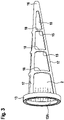
- 3 shows the filter device 100 from 2 in a perspective view without an optional line body 3 and without an optional housing 4.
- the filter device 100 has a carrier structure 1 and a filter medium 2 .
- a line body 3 can also be provided.
- the filter device 100 can have an optional housing 4 .
- the support structure 1 can in particular have an end frame 13 , an end body or an end piece 16 and at least two longitudinal struts 17 .
- the support structure 1 comprises a flow body 14.
- one or several crossbars 18 can be provided, as is the case in particular in 3 is shown as an example.
- the end frame 13 can be ring-shaped, for example, as in FIG 3 shown as an example, but is not limited to this form.
- the end frame 13 can be a closed frame that defines an opening 13A.
- the end frame 13 forms a first end 11 of the support structure 1 with respect to a longitudinal axis L1.
- the end frame 13 can in particular be formed from a plastic material, such as a duroplastic or a thermoplastic plastic material, or from a fiber-reinforced plastic material.
- the end body 16 is spaced apart from the end frame 13 along the longitudinal axis L1, as shown in FIG 2 is shown by way of example, and forms a second end 12 of the support structure 1 with respect to the longitudinal axis L1.
- the end body 16 can have a substantially triangular or trapezoidal cross-section.
- the longitudinal axis L1 extends through a centroid of the opening 13A defined by the end frame 13 and through the end body 16, as shown in FIG 2 is shown purely as an example.
- the end body 16 has a smaller diameter or a smaller extent than the end frame 13 in relation to a radial direction R1 running perpendicular to the longitudinal axis L1.
- the end body 16 can in particular be made of a plastic material, such as a duroplastic or a thermoplastic plastic material or formed from a fiber reinforced plastics material.
- the longitudinal struts 17 extend between the end frame 13 and the end body 16 and connect the end body 16 and the end frame 13.
- the longitudinal struts 17 can be realized, for example, as straight-extending strips or rods.
- the longitudinal struts 17 extend helically around the longitudinal axis L1 between the end frame 13 and the end body 16 .
- the longitudinal struts 17 are arranged spaced apart from one another, in particular with respect to an axis enclosing the longitudinal axis L1 circumferential direction.
- the longitudinal struts 17 delimit an interior space 10 that tapers from the first end 11 to the second end 12 of the support structure 1. If the end frame 13 as in 1 is annular, the result is a conical support structure 1. Alternatively, other tapering shapes are also conceivable, such as a pyramid shape or a truncated pyramid.
- the free spaces that result between the longitudinal struts 17 in relation to the circumferential direction form passages 15 from the interior 10 to an environment lying on the outside in relation to the radial direction R1.
- the circumferential struts 18 are arranged between the first and the second end 11, 12 and extend along the circumferential direction between or connect at least two adjacent longitudinal struts 17.
- the circumferential struts 18, as in FIG 3 shown by way of example extend around the entire circumference or enclose the longitudinal axis L1. If more than one peripheral strut 18 is provided, for example three peripheral struts 18, as in 3 shown by way of example, these are arranged at a distance from one another along the longitudinal axis L1 and can, for example, run parallel to one another.
- the passages 15 are thus designed as windows between the longitudinal struts 17 and the circumferential struts 18 .
- the longitudinal struts 17 and the circumferential struts 18 can in particular be formed from a plastic material, such as a duroplastic or a thermoplastic plastic material, or from a fiber-reinforced plastic material.
- a plastic material such as a duroplastic or a thermoplastic plastic material
- the longitudinal struts 17, optionally the optional circumferential struts 18, the end frame 13 and the end body 16 are designed in one piece or are manufactured in one piece.
- the support structure 13 is not in the Figs. 2 and 3 described design with longitudinal and transverse struts 17, 18 limited.
- the carrier structure 13 can also have a tapering sleeve body which extends flatly around the longitudinal axis L1 and has a large number of openings or through-holes.
- the support structure 1 thus extends between a first end 11 and a second end 12 and defines an interior space 10 that tapers from the first end 11 to the second end 12.
- the flow body 14 is arranged at the second end 12 of the support structure 1 and protrudes into the interior space 10 .
- the flow body 14 can be arranged coaxially to the longitudinal axis L1, as in FIG 2 shown as an example.
- the flow body 14 is designed as a body that tapers in the direction of the first end 11 .
- the flow body 14 can be conical, as is shown in 2 is shown as an example.
- the flow body 14 extends from the end body 16 and spaced from the first end 11, for example spaced from the end frame 13, ends.
- the flow body 14 in the interior 10 can have an extension along the longitudinal axis L1, which is in a range between 10 percent and 20 percent of an extension of the support structure 1 along the longitudinal axis L1 between the first end 11 and the second end 12.
- the flow body 14 can, for example, be formed in one piece with the end body 16, in particular made of a plastic material, as described above for the end body 16.
- the filter medium 2 is in 2 shown partially transparent and can be implemented as a hollow body extending between a first end 21 and a second end 22 , which tapers from the first to the second end 22 .
- the shape of the filter medium 2 can be adapted to the interior space 10 of the support structure 1 .
- the filter medium 2 is designed as a conical hollow body.
- the filter medium 2 can be porous or perforated, for example, and is generally permeable to liquid and/or gaseous fluids.
- the filter medium 2 is accommodated in the interior 10 of the support structure 1, with the first end 21 of the filter medium 2 in the area of the first end 11 of the support structure 1 and the second end 21 of the filter medium 2 in the area of the second end 12 of the support structure 1 is arranged.
- the first end 21 of the filter medium 2 can be attached to the end frame 13, for example.
- the second end 22 of the The filter medium 2 can have an opening, for example, through which the flow body 14 of the support structure 1 protrudes.
- the filter medium 2 can optionally also be attached to the longitudinal struts 17 and/or the transverse struts 18 .
- the optional line body 3 can be implemented as a piece of pipe.
- the conduit body 3 defines a flow channel 30 extending between an inlet port 31 and an outlet port 32.
- the flow channel 30 may have a first section or inlet section 33 extending from the inlet port 31 and a second section or outlet section 34 connecting the first section 33 to the outlet port 32 .
- the first section or inlet section 33 can in particular have a constant flow cross section or diameter.
- the inlet section 33 can be cylindrical or rectangular.
- the second section or outlet section 34 may have a flow area or diameter that widens toward the outlet opening 32 .
- the outlet portion 34 may be conical or frusto-pyramidal.
- the flow channel 30 can also widen continuously from the inlet opening 31 to the outlet opening 32 .
- the flow channel 30 thus has at least one outlet section 34 that widens towards the outlet opening 32 .
- the outlet section 34 or the outlet opening 32 faces the support structure 1 and protrudes at the first end 11 into the interior 10 of the support structure 1 .
- the line body 3 extends through the opening 13A of the end frame 13 into the cavity bounded by the filter medium 2 . Fluid can thus be transported through the flow channel 30 into the interior space 10 or the cavity and out of it.
- the second section 34 which widens towards the outlet opening 32 , advantageously reduces flow losses.
- the optional housing 4 defines a space between a first opening 41 and a second opening 42 extending receiving space 40.
- the support structure 1 is accommodated in the accommodation space 40 of the housing 4 .
- the first end 11 of the support structure 1 is located facing the first opening 41 or the first end 11 of the support structure 1 can be located in the first opening 41 .
- an outer circumference of the support structure 1, for example the end frame 13 can be connected to an inner circumference of the housing 4, for example welded, glued or latched to it.
- the line body 3 can have a connection structure 35 formed on its outer circumference, which can be arranged, for example, in the area of the outlet section 34 .
- the connection structure 35 can be, for example, a collar 36 protruding from the outer circumference, which extends along the longitudinal axis L1.
- the collar 36 can be accommodated in a gap 45 which, with respect to the radial direction R1, is formed between the first end 11 of the support structure 1, for example between a section of the end frame 13, and the housing 4 in the region of the first opening 41 is.
- the collar 36 can, for example, be locked, glued, welded or fastened in some other way.
- the line body 3 can be connected to the carrier structure 1 and/or the housing 4 .
- the filter device described is not limited to use in cooling circuits of fuel cell systems, but can generally be used as a filter, in particular as a particle filter, in flow channels, both for filtering liquid and gaseous media.
Landscapes
- Chemical & Material Sciences (AREA)
- Chemical Kinetics & Catalysis (AREA)
- Fuel Cell (AREA)
- Filtration Of Liquid (AREA)
Abstract
Description
- Die vorliegende Erfindung betrifft eine Filtereinrichtung, insbesondere für ein flüssiges Medium wie beispielsweise ein Kühlmedium in einem Kühlkreislauf eines Brennstoffzellensystems, sowie ein Brennstoffzellensystem mit einer solchen Filtereinrichtung.
- Brennstoffzellen kommen zunehmend als Energiewandler, unter anderem auch in Fahrzeugen, zum Einsatz, um in einem Brennstoff, wie z.B. Wasserstoff, gespeicherte chemische Energie zusammen mit Sauerstoff direkt in elektrische Energie umzuwandeln. Brennstoffzellen weisen typischerweise eine Anode, eine Kathode und eine zwischen Anode und Kathode angeordnete elektrolytische Membran auf. An der Anode erfolgt eine Oxidation des Brennstoffs und an der Kathode eine Reduktion des Sauerstoffs.
- Bei der in der Brennstoffzelle ablaufenden chemischen Reaktion wird Wärme frei, welche üblicherweise über einen Kühlkreislauf abgeführt wird, insbesondere um ein Überhitzen der Membran zu verhindern und den Wirkungsgrad der Brennstoffzelle zu verbessern.
- In der
WO 2017/036878 A1 und derUS 7 655 098 B2 werden jeweils Kühlkreisläufe für Brennstoffzellensysteme offenbart, in denen ein flüssiges Kühlmedium, wie entionisiertes Wasser, zirkuliert wird, wobei die Kühlkreisläufe jeweils Filtereinrichtungen zum Filtern des Kühlmediums enthalten. - Erfindungsgemäß sind eine Filtereinrichtung mit den Merkmalen des Anspruchs 1 sowie ein Brennstoffzellensystem mit den Merkmalen des Anspruchs 10 vorgesehen.
- Gemäß einem ersten Aspekt der Erfindung ist eine Filtereinrichtung, insbesondere für ein flüssiges Medium wie beispielsweise ein Kühlmedium in einem Kühlkreislauf eines Brennstoffzellensystems vorgesehen. Die Filtereinrichtung umfasst eine sich zwischen einem ersten Ende und einem zweiten Ende erstreckende Trägerstruktur, welche einen von dem ersten Ende zu dem zweiten Ende hin verjüngenden Innenraum definiert, und ein Filtermedium, welches in dem Innenraum der Trägerstruktur aufgenommen ist. Die Trägerstruktur weist an dem zweiten Ende einen in Richtung des ersten Endes in den Innenraum hineinragenden Strömungskörper auf, welcher sich in Richtung des ersten Endes verjüngt, wobei die Trägerstruktur Durchgänge aufweist, welche den Innenraum fluidisch leitend mit einer Umgebung der Trägerstruktur verbinden.
- Gemäß einem zweiten Aspekt der Erfindung umfasst ein Brennstoffzellensystem, eine Brennstoffzellenanordnung mit zumindest einer Brennstoffzelle und einen thermisch an die Brennstoffzellenanordnung gekoppelten Kühlkreislauf, welcher dazu eingerichtet ist, ein Kühlmittel zu zirkulieren, wobei der Kühlkreislauf eine Filtereinrichtung nach einem der voranstehenden Ansprüche aufweist, um das Kühlmittel zu filtern.
- Eine der Erfindung zugrundeliegende Idee besteht darin, die Filtereinrichtung mit einer sich in einer ersten Durchströmungsrichtung verjüngenden Form auszubilden, um einen durch die Filtereinrichtung erzeugten Druckverlust zu reduzieren. Insbesondere ist hierzu eine mechanisch robuste Trägerstruktur oder Hülle vorgesehen, welche an einem ersten Ende eine Öffnung definiert, in welche das Kühlmittel einströmen kann, und an einem zweiten Ende einen Strömungs- oder Staukörper aufweist, welcher sich entlang der Strömungsrichtung aufweitet. Dadurch wird das Kühlmittel in einer radialen Richtung abgelenkt und es werden vorteilhaft Verwirbelungen und ähnliche Strömungsverluste im Bereich des zweiten Endes der Trägerstruktur reduziert. Gleichzeitig kann auch bei einer Durchströmung in einer zweiten Durchströmungsrichtung entgegengesetzt zu der ersten Durchströmungsrichtung vorteilhaft eine Verringerung von Verlusten erzielt werden.
- Allgemein kann sich die Trägerstruktur entlang einer Längsachse erstrecken, welche vorzugsweise eine Mittelachse definiert. Die radiale Richtung erstreckt sich senkrecht zur Mittelachse. Das Filtermedium, ist in Bezug auf die radiale Richtung innen in der Trägerstruktur angeordnet und wird durch diese in radialer Richtung gestützt. Dadurch wird der Druck, bei dem die Filtereinrichtung arbeiten kann vorteilhaft vergrößert, wobei Beschädigungen des Filtermediums durch die Trägerstruktur vorgebeugt wird.
- Das Filtermedium ist insbesondere zum Filtern bzw. Abscheiden von Partikeln aus einer Fluidströmung ausgebildet, erstreckt sich ebenfalls zwischen einem ersten und einem zweiten Ende und verjüngt sich zu dem zweiten Ende hin, vorzugsweise konisch. Das Filtermedium ist somit derart in dem Innenraum der Trägerstruktur aufgenommen, dass das zweite Ende des Filtermediums dem zweiten Ende der Trägerstruktur und das erste Ende des Filtermediums dem ersten Ende der Trägerstruktur zugewandt gelegen ist. Auf diese Weise kann die Trägerstruktur besonders einfach hergestellt werden, z.B. indem diese um das Filtermedium herum geformt wird, z.B. in einem Gießverfahren oder einem 3D-Druckverfahren.
- Vorteilhafte Ausgestaltungen und Weiterbildungen ergeben sich aus den weiteren Unteransprüchen sowie aus der Beschreibung unter Bezugnahme auf die Figuren der Zeichnung.
- Gemäß manchen Ausführungsformen kann vorgesehen sein, dass die Trägerstruktur konisch ausgebildet ist. Insbesondere kann der Innenraum sich konisch um eine Mittelachse erstrecken, wobei der Strömungskörper koaxial zu der Mittelachse angeordnet ist. Die konische Form ist vorteilhaft, um Strömungsverluste weiter zu reduzieren. Ferner wird die Fertigung der Filtereinrichtung erleichtert.
- Gemäß manchen Ausführungsformen kann vorgesehen sein, dass der Strömungskörper konisch ausgebildet ist. Insbesondere ist hierbei eine Spitze des Strömungskörpers dem ersten Ende der Trägerstruktur zugewandt. Wenn die Trägerstruktur selbst konisch ist, ist der Konus des Strömungskörpers somit umgekehrt zu dem Konus der Trägerstruktur orientiert.
- Gemäß manchen Ausführungsformen kann vorgesehen sein, dass die Trägerstruktur einen das erste Ende bildenden Endrahmen, eine das zweite Ende bildenden Endkörper und zumindest zwei an dem Rahmen beanstandet zueinander angeordnete Längsstreben aufweist, welche den Endkörper und den Endrahmen verbinden, wobei die Durchgänge zwischen den Längsstreben ausgebildet sind. Die Trägerstruktur ist somit als eine Art Gerüst realisiert. Der Endrahmen definiert eine Öffnung und kann beispielsweise ringförmig gestaltet sein. Der Endkörper kann insbesondere eine Spitze der Trägerstruktur bilden. Der Strömungskörper ist vorzugsweise einstückig mit dem Endkörper ausgebildet. Beispielsweise kann auch der Endkörper als Konus realisiert sein. Die Längsstreben sind in Bezug auf eine sich um die Mittel- oder Längsachse herum erstreckende Umfangsrichtung beabstandet und können ebenfalls einstückig mit dem Endkörper und/oder dem Endrahmen ausgebildet sein. Die Durchgänge sind in diesem Fall durch die Bereiche zwischen den Längsstreben ausgebildet. Ein Vorteil der gerüstförmigen Gestaltung liegt darin, dass diese mechanisch robust ist und große Durchgänge gebildet werden, so dass der Strömungsverlust durch die Filtereinrichtung weiter reduziert wird.
- Gemäß manchen Ausführungsformen kann vorgesehen sein, dass die Trägerstruktur zumindest eine zwischen dem Endrahmen und dem Endkörper angeordnete Umfangsstreben aufweist, welche die Längsstreben miteinander verbindet, wobei die Durchgänge zwischen den Längsstreben und dem Umfangsstreben ausgebildet sind. Somit können zusätzlich zu den Längsstreben eine oder mehrere Umfangsstreben vorgesehen sein, welche sich quer zu den Längsstreben erstrecken, wobei jede Umfangsstrebe zumindest zwei Längsstreben miteinander verbindet. Beispielsweise können die Umfangsstreben als ringförmige oder allgemein geschlossene Rahmen ausgebildet sein, welche die Mittelachse oder Längsachse vollständig umschließen. Die Durchgänge sind aufgrund der Umfangsstreben somit als Fenster zwischen den Längs- und den Umfangstreben ausgebildet. Ein Vorteil der Umfangsstreben liegt darin, dass die Trägerstruktur mechanisch noch robuster wird und somit der Arbeitsdruck eines Kühlsystems bzw. allgemein des Mediums, das durch den Filter geleitet wird, weiter vergrößert werden kann.
- Gemäß manchen Ausführungsformen kann vorgesehen sein, dass die Trägerstruktur aus einem Kunststoffmaterial, insbesondere einem duroplastischen Kunststoffmaterial, einem thermoplastischen Kunststoffmaterial oder einem faserverstärkten Kunststoffmaterial gebildet ist. Auf diese Weise kann die Trägerstruktur sehr einfach hergestellt werden, z.B. in einem Spritzgussverfahren oder einem additiven Herstellungsverfahren, wie 3D-Druck.
- Gemäß manchen Ausführungsformen kann vorgesehen sein, dass Filtereinrichtung einen an dem ersten Ende in den Innenraum der Trägerstruktur hineinragenden Leitungskörper aufweist, welcher einen sich zwischen einer Einlassöffnung und einer Auslassöffnung erstreckenden Strömungskanal definiert, wobei die Auslassöffnung dem Innenraum der Trägerstruktur zugewandt gelegen ist; und wobei der Strömungskanal einen sich zu der Auslassöffnung hin weitenden, insbesondere konisch weitenden, Auslassabschnitt aufweist. Der Strömungskanal kann insbesondere in die Trägerstruktur hineinragen, wobei durch den sich aufweitenden Strömungsquerschnitt im Auslassabschnitt des Strömungskanals Querschnittssprünge entlang des Strömungspfads und damit Druckverluste auf effiziente und einfache Weise reduziert werden.
- Gemäß manchen Ausführungsformen kann vorgesehen sein, dass der Strömungskanal einen Zufuhrabschnitt aufweist, welcher sich mit konstantem Strömungsquerschnitt erstreckt, insbesondere zylindrisch, und wobei der Auslassabschnitt sich an den Zufuhrabschnitt anschließt. Somit werden einfache geometrische Strukturen realisiert, die sich leicht herstellen lassen. Beispielsweise kann der Zufuhrabschnitt sich von der Einlassöffnung aus erstrecken, wobei sich der Auslassabschnitt von einem abgewandt von der Einlassöffnung gelegenen Ende des Zufuhrabschnitts aus erstreckt und an der Auslassöffnung endet.
- Gemäß manchen Ausführungsformen kann vorgesehen sein, dass die Filtereinrichtung ein Gehäuse aufweist, welches einen sich zwischen einer ersten Öffnung und einer zweiten Öffnung erstreckenden Aufnahmeraum definiert, wobei die Trägerstruktur derart in den Aufnahmeraum aufgenommen ist, dass das erste Ende der Trägerstruktur der ersten Öffnung zugewandt gelegen ist. Der optionale Leitungskörper kann gegebenenfalls z.B. im Bereich der ersten Öffnung mit dem Gehäuse verbunden sein und sich durch die erste Öffnung hindurch erstrecken bzw. in diese hineinragen. Das Gehäuse bildet somit einen Leitungsabschnitt zum Leiten von Kühlmedium aus.
- Im Folgenden wird die Erfindung unter Bezugnahme auf die Figuren der Zeichnungen erläutert. Von den Figuren zeigen:
- Fig. 1
- eine schematische Ansicht eines hydraulischen Schaltbilds eines Brennstoffzellensystems gemäß einem Ausführungsbeispiel der Erfindung;
- Fig. 2
- eine schematische Schnittansicht einer Filtereinrichtung gemäß einem Ausführungsbeispiel der Erfindung; und
- Fig. 3
- eine perspektivische Ansicht einer Filtereinrichtung gemäß einem Ausführungsbeispiel der Erfindung.
- In den Figuren bezeichnen dieselben Bezugszeichen gleiche oder funktionsgleiche Komponenten, soweit nichts Gegenteiliges angegeben ist.
-
Fig. 1 zeigt schematisch ein Brennstoffzellensystem 200. Das Brennstoffzellensystem 200 weist eine Brennstoffzellenanordnung 210 und einen Kühlkreislauf 220 zum Kühlen der Brennstoffzellenanordnung 210 auf. - Wie in
Fig. 1 schematisch dargestellt, kann die Brennstoffzellenanordnung 210 ein Vielzahl von Brennstoffzellen 211 aufweisen, welche z.B. zu einem sogenannten Stack verbaut sein können. Grundsätzlich weist die Brennstoffzellenanordnung 210 zumindest eine Brennstoffzelle 211 auf. Jede Brennstoffzelle 211 weist eine Kathode (nicht gezeigt), eine Anode (nicht gezeigt) und einen zwischen der Kathode und der Anode angeordneten Elektrolyten (nicht gezeigt) auf, z.B. in Form einer Membran. Die Brennstoffzellenanordnung 210 ist dazu eingerichtet, bei Zufuhr von Brennstoff, wie z.B. Wasserstoff, an die Anode und Zufuhr von Sauerstoff an die Kathode elektrische Energie zu erzeugen. An der Anode erfolgt eine Oxidation des Brennstoffs und an der Kathode eine Reduktion des Sauerstoffs. Wie inFig. 1 schematisch dargestellt, kann die Brennstoffzellenanordnung 211 hierzu einen Brennstoffzufuhranschluss 212 zum Zuführen von Brennstoff an die Anode und einen Brennstoffabfuhranschluss 213 zum Abführen von nicht reagiertem Brennstoff von der Anode aufweisen. Ferner kann die Brennstoffzellenanordnung 211 einen Sauerstoffzufuhranschluss 214 zum Zuführen von Brennstoff an die Kathode und einen Sauerstoffabfuhranschluss 215 zum Abführen der Reaktionsprodukte von der Kathode aufweisen. - Der Kühlmittelkreislauf 220 ist in
Fig. 1 lediglich schematisch dargestellt und dient zum Zirkulieren eines Kältemittels oder Kühlmediums, welches Wärme mit der Brennstoffzellenanordnung 210 austauscht. Wie inFig. 1 beispielhaft gezeigt, kann der Kühlmittelkreislauf 220 eine Pumpe oder einen Verdichter 221, eine Filtereinrichtung 100 und einen Wärmetauscher 222 aufweisen. - Der Verdichter 221 ist dazu eingerichtet, das Kühlmedium zu fördern. Das Kühlmedium kann gasförmig oder flüssig sein. Beispielsweise kann als Kühlmedium entionisiertes Wasser oder eine andere Flüssigkeit verwendet werden. Ein Druckausgang des Verdichters 221 ist fluidisch leitend mit einem Kühlmitteleingang 216 der Brennstoffzellenanordnung 210 verbunden, z.B. durch eine Zufuhrleitung 223. Ein Saugeingang des Verdichters 222 ist mit einem Kühlmittelausgang 217 der der Brennstoffzellenanordnung 210 fluidisch leitend verbunden, z.B. über eine Saugleitung 224.
- Wie in
Fig. 1 schematisch dargestellt, ist der Wärmetauscher 222 zwischen dem Saugeingang des Verdichters 222 und dem Kühlmittelausgang 217 angeordnet, so dass diesem durch die Saugleitung 224 das aus der Brennstoffzellenanordnung 210 kommende Kühlmittel zuführbar ist. Der Wärmetauscher 222 ist an eine Wärmesenke, wie z.B. die Umgebung, gekoppelt, um dem Kühlmittel Wärme zu entziehen. Somit kann der Brennstoffzellenanordnung 210 durch den Verdichter 221 Kühlmittel zugeführt werden und der Brennstoffzellenanordnung 210 Wärme entziehen, wobei dem Kühlmittel in dem Wärmetauscher 222 wiederum Wärme entzogen wird. In der Brennstoffzellenanordnung 210 kann das Kühlmittel z.B. in einer thermisch leitend mit den Brennstoffzellen 211 verbundenen Kanalanordnung (nicht gezeigt) geleitet werden. Allgemein ist der Kältemittelkreislauf 210 thermisch an die Brennstoffzellenanordnung 210 gekoppelt. - Die Filtereinrichtung 100 kann insbesondere zwischen dem Druckausgang des Verdichters 221 und dem Kühlmitteleingang 216 der Brennstoffzellenanordnung 210 angeordnet sein, z.B. in der Zufuhrleitung 223, wie dies in
Fig. 1 rein beispielhaft gezeigt ist. Grundsätzlich ist jedoch auch denkbar, dass die Filtereinrichtung 100 zwischen dem Saugeingang des Verdichters 222 und dem Kühlmittelausgang 217 angeordnet ist, z.B. in der Saugleitung 223. Die Filtereinrichtung 100 dient insbesondere zum Abscheiden bzw. Filtern von Partikeln, die im Kühlmittel vorhanden sein können. Beispielsweise können sich durch Verschleiß in verschiedenen Komponenten des Kühlmittelkreislaufs, wie dem Verdichter 221, Ventilen (nicht gezeigt) oder dem Wärmetauscher 222, Partikel lösen, welche durch das Kühlmittel abtransportiert werden und dadurch in die Brennstoffzellenanordnung 210 gelangen können. -
Fig. 2 zeigt rein beispielhaft eine Schnittansicht der Filtereinrichtung 100.Fig. 3 zeigt die Filtereinrichtung 100 ausFig. 2 in einer perspektivischen Ansicht ohne einen optionalen Leitungskörper 3 und ohne ein optionales Gehäuse 4. - Wie in
Fig. 2 beispielhaft gezeigt, weist die Filtereinrichtung 100 eine Trägerstruktur 1 und ein Filtermedium 2 auf. Optional kann zusätzlich, wie erwähnt, ein Leitungskörper 3 vorgesehen sein. Ebenso zeigtFig. 2 , dass die Filtereinrichtung 100 eine optionales Gehäuse 4 aufweisen kann. - Wie in den
Fign. 2 und3 beispielhaft gezeigt, kann die Trägerstruktur 1 insbesondere einen Endrahmen 13, einen Endkörper oder ein Endstück 16 und zumindest zwei Längsstreben 17 aufweisen. Wie inFig. 2 gezeigt ist, umfasst die Trägerstruktur 1 einen Strömungskörper 14. Weiter optional können ein oder mehrere Querstreben 18 vorgesehen sein wie dies insbesondere inFig. 3 beispielhaft gezeigt ist. - Der Endrahmen 13 kann beispielsweise ringförmig sein, wie in
Fig. 3 beispielhaft gezeigt, ist jedoch nicht auf diese Form beschränkt. Allgemein kann der Endrahmen 13 ein geschlossener Rahmen sein, welcher eine Öffnung 13A definiert. Der Endrahmen 13 bildet in Bezug auf eine Längsachse L1 ein erstes Ende 11 der Trägerstruktur 1. Der Endrahmen 13 kann insbesondere aus einem Kunststoffmaterial, wie z.B. einem duroplastischen oder einem thermoplastischen Kunststoffmaterial oder aus einem faserverstärkten Kunststoffmaterial gebildet sein. - Der Endkörper 16 ist entlang der Längsachse L1 beabstandet zu dem Endrahmen 13 angeordnet, wie dies in
Fig. 2 beispielhaft gezeigt ist, und bildet in Bezug auf die Längsachse L1 ein zweites Ende 12 der Trägerstruktur 1. Wie inFig. 2 beispielhaft dargestellt, kann der Endkörper 16 einen im wesentlichen dreieck- oder trapezförmigen Querschnitt aufweisen. Optional erstreckt sich die Längsachse L1 durch einen Flächenschwerpunkt der durch den Endrahmen 13 definierten Öffnung 13A und durch den Endkörper 16, wie dies inFig. 2 rein beispielhaft dargestellt ist. Wie inFig. 2 ferner gezeigt ist, weist der Endkörper 16 in Bezug auf eine senkrecht zur Längsachse L1 verlaufende radiale Richtung R1 einen geringeren Durchmesser oder eine geringere Erstreckung auf als der Endrahmen 13. Der Endkörper 16 kann insbesondere aus einem Kunststoffmaterial, wie z.B. einem duroplastischen oder einem thermoplastischen Kunststoffmaterial oder aus einem faserverstärkten Kunststoffmaterial gebildet sein. - Wie in den
Fign. 2 und3 weiterhin schematisch gezeigt ist, erstrecken sich die Längsstreben 17 zwischen dem Endrahmen 13 und dem Endkörper 16 und verbinden den Endkörper 16 und den Endrahmen 13. Die Längsstreben 17 können beispielsweise als sich gerade erstreckende Leisten oder Stäbe realisiert sein. Alternativ ist auch denkbar, dass die Längsstreben 17 sich schraubenförmig um die Längsachse L1 zwischen dem Endrahmen 13 und dem Endkörper 16 erstrecken. Die Längsstreben 17 sind entlang zueinander beabstandet angeordnet, insbesondere in Bezug auf eine die Längsachse L1 umschließende Umfangsrichtung. Da der Endkörper 16 in Bezug auf die radiale Richtung R1 einen geringeren Durchmesser als der Endrahmen 13 aufweist, begrenzen die Längsstreben 17 einen sich von dem ersten Ende 11 zu dem zweiten Ende 12 der Trägerstruktur 1 hin verjüngenden Innenraum 10. Wenn der Endrahmen 13 wie inFig. 1 ringförmig ist, ergibt sich eine konische Trägerstruktur 1. Alternativ sind auch andere sich verjüngende Formen denkbar, wie z.B. eine Pyramidenform oder ein Pyramidenstumpf. Die sich in Bezug auf die Umfangsrichtung zwischen den Längsstreben 17 ergebenden Freiräume bilden Durchgänge 15 vom Innenraum 10 zu einer in Bezug auf die radiale Richtung R1 außenliegende Umgebung. - Die Umfangsstreben 18 sind zwischen dem ersten und dem zweiten Ende 11, 12 angeordnet und erstrecken sich entlang der Umfangsrichtung zwischen bzw. verbinden zumindest zwei benachbarten Längsstreben 17. Optional können die Umfangsstreben 18, wie in
Fig. 3 beispielhaft gezeigt, sich um den gesamten Umfang erstrecken bzw. die Längsachse L1 umschließen. Wenn mehr als eine Umfangsstreben 18 vorgesehen ist, z.B. drei Umfangsstreben 18, wie inFig. 3 beispielhaft dargestellt, sind diese entlang der Längsachse L1 zueinander beabstandet angeordnet und können beispielsweise parallel zueinander verlaufen. Die Durchgänge 15 sind somit als Fenster zwischen den Längsstreben 17 und den Umfangsstreben 18 ausgebildet. - Die Längsstreben 17 und die Umfangsstreben 18 können insbesondere aus einem Kunststoffmaterial, wie z.B. einem duroplastischen oder einem thermoplastischen Kunststoffmaterial oder aus einem faserverstärkten Kunststoffmaterial gebildet sein. Optional sind die Längsstreben 17, gegebenenfalls die optionalen Umfangsstreben 18, der Endrahmen 13 und der Endkörper 16 einstückig ausgebildet bzw. in einem Stück hergestellt.
- Die Trägerstruktur 13 ist nicht auf die in den
Fign. 2 und3 beschriebene Gestaltung mit Längs- und Querstreben 17, 18 beschränkt. Beispielsweise kann die Trägerstruktur 13 auch einen sich flächig um die Längsachse L1 erstreckenden, sich verjüngenden Hülsenkörper mit einer Vielzahl an Durchbrüchen oder Öffnungen aufweisen. Allgemein erstreckt sich die Trägerstruktur 1 somit zwischen einem ersten Ende 11 und einem zweiten Ende 12 und definiert einen von dem ersten Ende 11 zu dem zweiten Ende 12 hin verjüngenden Innenraum 10. - Wie in
Fig. 2 erkennbar, ist der Strömungskörper 14 am zweiten Ende 12 der Trägerstruktur 1 angeordnet und ragt in den Innenraum 10 hinein. Insbesondere kann der Strömungskörper 14 koaxial zu der Längsachse L1 angeordnet sein, wie inFig. 2 beispielhaft dargestellt. Der Strömungskörper 14 ist als ein sich in Richtung des ersten Endes 11 verjüngender Körper ausgebildet. Beispielsweise kann der Strömungskörper 14 konisch sein, wie dies inFig. 2 beispielhaft gezeigt ist. Ferner ist inFig. 2 erkennbar, dass der Strömungskörper 14 sich von dem Endkörper 16 aus erstreckt und beabstandet zu dem ersten Ende 11, beispielsweise beabstandet zu dem Endrahmen 13, endet. Beispielsweise kann der Strömungskörper 14 in dem Innenraum 10 eine Erstreckung entlang der Längsachse L1 aufweisen, welche in einem Bereich zwischen 10 Prozent und 20 Prozent einer Erstreckung der Trägerstruktur 1 entlang der Längsachse L1 zwischen dem ersten Ende 11 und dem zweiten Ende 12 liegt. Der Strömungskörper 14 kann beispielsweise einstückig mit dem Endkörper 16 ausgebildet sein, insbesondere aus einem Kunststoffmaterial, wie oben für den Endkörper 16 beschrieben. - Das Filtermedium 2 ist in
Fig. 2 teilweise transparent dargestellt und kann als ein sich zwischen einem ersten Ende 21 und einem zweiten Ende 22 erstreckender Hohlkörper realisiert sein, welcher sich von dem ersten zu dem zweiten Ende 22 hin verjüngt. Beispielsweise kann das Filtermedium 2 in seiner Form an den Innenraum 10 der Trägerstruktur 1 angepasst sein. InFig. 2 ist beispielhaft gezeigt, dass das Filtermedium 2 als konischer Hohlkörper ausgebildet ist. Das Filtermedium 2 kann z.B. porös oder perforiert sein und ist allgemein durchlässig für flüssige und/oder gasförmige Fluide. - Wie in den
Fign. 2 und3 schematisch dargestellt, ist das Filtermedium 2 in dem Innenraum 10 der Trägerstruktur 1 aufgenommen, wobei das erste Ende 21 des Filtermediums 2 im Bereich des ersten Endes 11 der Trägerstruktur 1 und das zweite Ende 21 des Filtermediums 2 im Bereich des zweiten Endes 12 der Trägerstruktur 1 angeordnet ist. Das erste Ende 21 des Filtermediums 2 kann z.B. an dem Endrahmen 13 befestigt sein. Das zweite Ende 22 des Filtermediums 2 kann z.B. eine Öffnung aufweisen, durch welche der Strömungskörper 14 der Trägerstruktur 1 hindurch ragt. Das Filtermedium 2 kann optional auch an den Längsstreben 17 und/oder den Querstreben 18 befestigt sein. - Wie in
Fig. 2 beispielhaft gezeigt, kann der optionale Leitungskörper 3 kann als ein Rohrstück realisiert sein. Allgemein definiert der Leitungskörper 3 einen sich zwischen einer Einlassöffnung 31 und einer Auslassöffnung 32 erstreckenden Strömungskanal 30. Wie inFig. 2 beispielhaft gezeigt, kann der Strömungskanal 30 einen ersten Abschnitt oder Zulaufabschnitt 33 aufweisen, welcher sich von der Einlassöffnung 31 aus erstreckt, und einen zweiten Abschnitt oder Auslassabschnitt 34, welcher den ersten Abschnitt 33 mit der Auslassöffnung 32 verbindet. Der erste Abschnitt oder Zulaufabschnitt 33 kann insbesondere einen konstanten Strömungsquerschnitt oder Durchmesser aufweisen. Beispielsweise kann der Zulaufabschnitt 33 zylinderförmig oder rechteckförmig sein. Der zweite Abschnitt oder Auslassabschnitt 34 kann einen sich zu der Auslassöffnung 32 hin weitenden Strömungsquerschnitt oder Durchmesser aufweisen. Beispielsweise kann der Auslassabschnitt 34 konisch oder pyramidenstumpfförmig sein. Anstelle eines Zulaufabschnitts 33 mit konstanten Strömungsquerschnitt kann sich der Strömungskanal 30 auch kontinuierlich von der Einlassöffnung 31 zur Auslassöffnung 32 hin aufweiten. Allgemein weist der Strömungskanal 30 somit zumindest einen sich zu der Auslassöffnung 32 hin weitenden Auslassabschnitt 34 auf. - Wie in
Fig. 2 schematisch dargestellt, ist der Auslassabschnitt 34 bzw. die Auslassöffnung 32 der Trägerstruktur 1 zugewandt und ragt an dem ersten Ende 11 in den Innenraum 10 der Trägerstruktur 1 hinein. Insbesondere erstreckt sich der Leitungskörper 3 durch die Öffnung 13A des Endrahmens 13 hindurch in den durch das Filtermedium 2 umgrenzten Hohlraum hinein. Somit kann Fluid durch den Strömungskanal 30 in den Innenraum 10 bzw. den Hohlraum hinein und aus diesem heraus transportiert werden. Der sich zur Auslassöffnung 32 hin weitenden zweite Abschnitt 34 verringert dabei vorteilhaft Strömungsverluste. - Wie in
Fig. 2 weiterhin beispielhaft dargestellt ist, definiert das optionale Gehäuse 4 einen sich zwischen einer ersten Öffnung 41 und einer zweiten Öffnung 42 erstreckenden Aufnahmeraum 40. Das Gehäuse 4 kann, wie inFig. 2 beispielhaft gezeigt, insbesondere als ein Rohrstück realisiert sein. Die Trägerstruktur 1 ist in dem Aufnahmeraum 40 des Gehäuses 4 aufgenommen. Wie inFig. 2 gezeigt, ist hierbei das erste Ende 11 der Trägerstruktur 1 der ersten Öffnung 41 zugewandt gelegen bzw. kann das erste Ende 11 der Trägerstruktur 1 der ersten Öffnung 41 gelegen sein. Wie inFig. 2 schematisch gezeigt, kann ein Außenumfang der Trägerstruktur 1, z.B. des Endrahmens 13, mit einem Innenumfang des Gehäuses 4 verbunden sein, z.B. mit diesem verschweißt, verklebt oder verrastet. - Wie in
Fig. 2 ebenfalls schematisch und rein beispielhaft dargestellt ist, kann der Leitungskörper 3 eine an seinem Außenumfang ausgebildete Verbindungsstruktur 35 aufweisen, welche z.B. im Bereich des Auslassabschnitts 34 angeordnet sein kann. Die Verbindungsstruktur 35 kann beispielsweise ein von dem Außenumfang vorspringender Kragen 36 sein, welcher sich entlang der Längsachse L1 erstreckt. Wie inFig. 2 beispielhaft gezeigt, kann der Kragen 36 in einem Spalt 45 aufgenommen sein, welcher in Bezug auf die radiale Richtung R1 zwischen dem ersten Ende 11 der Trägerstruktur 1, z.B. zwischen einem Abschnitt des Endrahmens 13, und dem Gehäuse 4 im Bereich der ersten Öffnung 41 ausgebildet ist. Dort kann der Kragen 36 z.B. verrastet, verklebt, verschweißt oder in anderer Weise befestigt sein. Allgemein kann der Leitungskörper 3 mit der Trägerstruktur 1 und/oder dem Gehäuse 4 verbunden sein. - Obwohl die vorliegende Erfindung vorstehend anhand von Ausführungsbeispielen exemplarisch erläutert wurde, ist sie darauf nicht beschränkt, sondern auf vielfältige Weise modifizierbar. Insbesondere sind auch Kombinationen der voranstehenden Ausführungsbeispiele denkbar. Weiterhin ist die beschriebene Filtereinrichtung nicht auf den Einsatz in Kühlkreisläufen von Brennstoffzellensystemen beschränkt, sondern kann allgemein als Filter, insbesondere als Partikelfilter, in Strömungskanälen eingesetzt werden, sowohl zum Filtern von flüssigen als auch von gasförmigen Medien.
Claims (10)
- Filtereinrichtung (100), insbesondere für ein flüssiges Medium wie beispielsweise ein Kühlmedium in einem Kühlkreislauf (220) eines Brennstoffzellensystems (200), aufweisend:eine sich zwischen einem ersten Ende (11) und einem zweiten Ende (12) erstreckende Trägerstruktur (1), welche einen von dem ersten Ende (11) zu dem zweiten Ende (12) hin verjüngenden Innenraum (10) definiert,wobei die Trägerstruktur (1) an dem zweiten Ende (12) einen in Richtung des ersten Endes (11) in den Innenraum (10) hineinragenden Strömungskörper (14) aufweist, welcher sich in Richtung des ersten Endes (11) verjüngt, und wobei die Trägerstruktur (1) Durchgänge (15) aufweist, welche den Innenraum (10) fluidisch leitend mit einer Umgebung der Trägerstruktur (1) verbinden; undein Filtermedium (2), welches in dem Innenraum (10) der Trägerstruktur (1) aufgenommen ist.
- Filtereinrichtung (100) nach Anspruch 1, wobei die Trägerstruktur (1) konisch ausgebildet ist.
- Filtereinrichtung (100) nach Anspruch 1 oder 2, wobei der Strömungskörper (14) konisch ausgebildet ist.
- Filtereinrichtung (100) nach einem der voranstehenden Ansprüche, wobei die Trägerstruktur (1) einen das erste Ende (11) bildenden Endrahmen (13), eine das zweite Ende (12) bildenden Endkörper (16) und zumindest zwei an dem Rahmen beanstandet zueinander angeordnete Längsstreben (17) aufweist, welche den Endkörper (16) und den Endrahmen (13) verbinden, wobei die Durchgänge (15) zwischen den Längsstreben (17) ausgebildet sind.
- Filtereinrichtung (100) nach Anspruch 4, wobei die Trägerstruktur (1) zumindest eine zwischen dem Endrahmen (13) und dem Endkörper (16) angeordnete Umfangsstrebe (18) aufweist, welche die Längsstreben (17) miteinander verbindet, wobei die Durchgänge (15) zwischen den Längsstreben (17) und der zumindest einen Umfangsstrebe (18) ausgebildet sind.
- Filtereinrichtung (100) nach einem der voranstehenden Ansprüche, wobei die Trägerstruktur (1) aus einem Kunststoffmaterial, insbesondere einem duroplastischen Kunststoffmaterial, einem thermoplastischen Kunststoffmaterial oder einem faserverstärkten Kunststoffmaterial gebildet ist.
- Filtereinrichtung (100) nach einem der voranstehenden Ansprüche, zusätzlich aufweisend:einen an dem ersten Ende (11) in den Innenraum (10) der Trägerstruktur (1) hineinragenden Leitungskörper (3), welcher einen sich zwischen einer Einlassöffnung (31) und einer Auslassöffnung (32) erstreckenden Strömungskanal (30) definiert;wobei die Auslassöffnung (32) dem Innenraum (10) der Trägerstruktur (1) zugewandt gelegen ist; undwobei der Strömungskanal (30) einen sich zu der Auslassöffnung (32) hin weitenden, insbesondere konisch weitenden, Auslassabschnitt (34) aufweist.
- Filtereinrichtung (100) nach Anspruch 7, wobei der Strömungskanal einen Zufuhrabschnitt (33) aufweist, welcher sich mit konstantem Strömungsquerschnitt erstreckt, insbesondere zylindrisch, und wobei der Auslassabschnitt (34) sich an den Zufuhrabschnitt (33) anschließt.
- Filtereinrichtung (100) nach einem der voranstehenden Ansprüche, zusätzlich aufweisend:ein Gehäuse (4), welches einen sich zwischen einer ersten Öffnung (41) und einer zweiten Öffnung (42) erstreckenden Aufnahmeraum (40) definiert;wobei die Trägerstruktur (1) derart in den Aufnahmeraum (40) aufgenommen ist, dass das erste Ende (11) der Trägerstruktur (1) der ersten Öffnung (41) zugewandt gelegen ist.
- Brennstoffzellensystem (200), aufweisend:eine Brennstoffzellenanordnung (210) mit zumindest einer Brennstoffzelle (211); undeinem thermisch an die Brennstoffzellenanordnung (210) gekoppelten Kühlkreislauf (220), welcher dazu eingerichtet ist, ein Kühlmittel zu zirkulieren, wobei der Kühlkreislauf (220) eine Filtereinrichtung (100) nach einem der voranstehenden Ansprüche aufweist, um das Kühlmittel zu filtern.
Priority Applications (4)
| Application Number | Priority Date | Filing Date | Title |
|---|---|---|---|
| EP21176840.3A EP4098345B1 (de) | 2021-05-31 | 2021-05-31 | Filtereinrichtung und brennstoffzellensystem mit filtereinrichtung |
| PCT/EP2022/061207 WO2022253494A1 (de) | 2021-05-31 | 2022-04-27 | Filtereinrichtung und brennstoffzellensystem mit filtereinrichtung |
| US18/564,694 US20240269584A1 (en) | 2021-05-31 | 2022-04-27 | Filter device and fuel cell system having a filter device |
| CN202280038013.0A CN117396262A (zh) | 2021-05-31 | 2022-04-27 | 过滤器装置和具有过滤器装置的燃料电池系统 |
Applications Claiming Priority (1)
| Application Number | Priority Date | Filing Date | Title |
|---|---|---|---|
| EP21176840.3A EP4098345B1 (de) | 2021-05-31 | 2021-05-31 | Filtereinrichtung und brennstoffzellensystem mit filtereinrichtung |
Publications (2)
| Publication Number | Publication Date |
|---|---|
| EP4098345A1 true EP4098345A1 (de) | 2022-12-07 |
| EP4098345B1 EP4098345B1 (de) | 2024-02-14 |
Family
ID=76197325
Family Applications (1)
| Application Number | Title | Priority Date | Filing Date |
|---|---|---|---|
| EP21176840.3A Active EP4098345B1 (de) | 2021-05-31 | 2021-05-31 | Filtereinrichtung und brennstoffzellensystem mit filtereinrichtung |
Country Status (4)
| Country | Link |
|---|---|
| US (1) | US20240269584A1 (de) |
| EP (1) | EP4098345B1 (de) |
| CN (1) | CN117396262A (de) |
| WO (1) | WO2022253494A1 (de) |
Cited By (2)
| Publication number | Priority date | Publication date | Assignee | Title |
|---|---|---|---|---|
| IT202300003489A1 (it) * | 2023-02-27 | 2024-08-27 | Gvs Spa | Elemento filtrante monopezzo per impianto di ricircolo di un fluido per impianto di climatizzazione quale quello di raffreddamento di un gruppo batterie in particolare per autotrazione elettrica |
| EP4483982A1 (de) | 2023-06-30 | 2025-01-01 | Hutchinson | Filtervorrichtung, insbesondere für einen kühlkreislauf |
Families Citing this family (1)
| Publication number | Priority date | Publication date | Assignee | Title |
|---|---|---|---|---|
| DE102023102799A1 (de) * | 2023-02-06 | 2024-08-08 | Mann+Hummel Gmbh | Konusförmiges Filterelement, insbesondere Luftfilterelement |
Citations (5)
| Publication number | Priority date | Publication date | Assignee | Title |
|---|---|---|---|---|
| JPS6448221U (de) * | 1987-09-21 | 1989-03-24 | ||
| US7655098B2 (en) | 2003-10-14 | 2010-02-02 | Ford Motor Company | Readying cooling circuits for use in fuel cells |
| WO2017036878A1 (de) | 2015-08-28 | 2017-03-09 | Volkswagen Ag | Kühlsystem für eine brennstoffzelle und brennstoffzellensystem |
| DE102019121342A1 (de) * | 2018-08-15 | 2020-02-20 | Mann+Hummel Gmbh | Filterelement für den Einsatz als Partikelfilter in einem Kühlkreislauf eines elektrochemischen Energiewandlers und Anordnung mit einem elektrochemischen Energiewandler und einem Kühlkreislauf |
| US20210001251A1 (en) * | 2018-04-25 | 2021-01-07 | Yamashin-Filter Corp. | Strainer |
-
2021
- 2021-05-31 EP EP21176840.3A patent/EP4098345B1/de active Active
-
2022
- 2022-04-27 US US18/564,694 patent/US20240269584A1/en active Pending
- 2022-04-27 WO PCT/EP2022/061207 patent/WO2022253494A1/de not_active Ceased
- 2022-04-27 CN CN202280038013.0A patent/CN117396262A/zh active Pending
Patent Citations (5)
| Publication number | Priority date | Publication date | Assignee | Title |
|---|---|---|---|---|
| JPS6448221U (de) * | 1987-09-21 | 1989-03-24 | ||
| US7655098B2 (en) | 2003-10-14 | 2010-02-02 | Ford Motor Company | Readying cooling circuits for use in fuel cells |
| WO2017036878A1 (de) | 2015-08-28 | 2017-03-09 | Volkswagen Ag | Kühlsystem für eine brennstoffzelle und brennstoffzellensystem |
| US20210001251A1 (en) * | 2018-04-25 | 2021-01-07 | Yamashin-Filter Corp. | Strainer |
| DE102019121342A1 (de) * | 2018-08-15 | 2020-02-20 | Mann+Hummel Gmbh | Filterelement für den Einsatz als Partikelfilter in einem Kühlkreislauf eines elektrochemischen Energiewandlers und Anordnung mit einem elektrochemischen Energiewandler und einem Kühlkreislauf |
Cited By (4)
| Publication number | Priority date | Publication date | Assignee | Title |
|---|---|---|---|---|
| IT202300003489A1 (it) * | 2023-02-27 | 2024-08-27 | Gvs Spa | Elemento filtrante monopezzo per impianto di ricircolo di un fluido per impianto di climatizzazione quale quello di raffreddamento di un gruppo batterie in particolare per autotrazione elettrica |
| WO2024180406A1 (en) * | 2023-02-27 | 2024-09-06 | Gvs S.P.A. | Single piece filtering element for a fluid recirculation system for an air conditioning system such as a system for cooling a battery assembly in particular for electric vehicles |
| EP4483982A1 (de) | 2023-06-30 | 2025-01-01 | Hutchinson | Filtervorrichtung, insbesondere für einen kühlkreislauf |
| FR3150445A1 (fr) * | 2023-06-30 | 2025-01-03 | Hutchinson | Dispositif de filtration, en particulier pour un circuit de refroidissement |
Also Published As
| Publication number | Publication date |
|---|---|
| CN117396262A (zh) | 2024-01-12 |
| WO2022253494A1 (de) | 2022-12-08 |
| US20240269584A1 (en) | 2024-08-15 |
| EP4098345B1 (de) | 2024-02-14 |
Similar Documents
| Publication | Publication Date | Title |
|---|---|---|
| WO2022253494A1 (de) | Filtereinrichtung und brennstoffzellensystem mit filtereinrichtung | |
| DE102019121342B4 (de) | Filterelement für den Einsatz als Partikelfilter in einem Kühlkreislauf eines elektrochemischen Energiewandlers und Verwendung des Filterelements in einer Anordnung mit einem elektrochemischen Energiewandler und einem Kühlkreislauf | |
| EP1444474B1 (de) | Wärmeübertrager | |
| DE2116456A1 (de) | Membranpumpe zur Förderung flüssiger oder gasförmiger Medien | |
| DE102016204474B4 (de) | Wärmetauscher und Brennstoffzellensystem | |
| EP1474625B1 (de) | Bersteinsatz | |
| DE112013007048T5 (de) | Fluiddruckzylinder | |
| DE202021102441U1 (de) | Temperiervorrichtung für einzelne, zu einem Modul zusammengesetzte Batteriezellen | |
| DE2601065C2 (de) | Elektrolysevorrichtung | |
| DE102017212817A1 (de) | Welle, Radialverdichter und Verfahren zum Herstellen eines Radialverdichters | |
| DD139796A5 (de) | Filteranordnung | |
| DE3879708T2 (de) | Vorrichtung zur membranabtrennung und trennverfahren. | |
| DE102011109844B3 (de) | Brennstoffzelle und Brennstoffzellenanordnung | |
| DE2800425C3 (de) | Filteranordnung | |
| DE102013015519A1 (de) | Vorrichtung zum Speichern von Gas | |
| DE102017211286A1 (de) | Kühlvorrichtung zum Kühlen zumindest zweier Batteriemodule | |
| DE2814326A1 (de) | Poroese abstuetzung zur verwendung in einer trenneinrichtung mit hohlfasern | |
| DE102015010288A1 (de) | Wärmetauscher, Behälter für Wärmetauscher und Verfahren zur Herstellung desselben | |
| DD144601A5 (de) | Waermeaustauscher | |
| EP2987952A1 (de) | Dampfturbine und Verfahren zum Betrieb einer Dampfturbine | |
| DE102021200008A1 (de) | Verfahren und Vorrichtung zur Rezirkulation von Anodengas in einem Anodenkreis eines Brennstoffzellensystems, Brennstoffzellensystem | |
| DE102012100646A1 (de) | Turbinen- und/oder Generatorgehäuse | |
| DE102020114164A1 (de) | Druckspeicher | |
| DE112013007086T5 (de) | Fluiddruckzylinder | |
| DE102019214844A1 (de) | Plattenwärmeübertrager und Anordnung eines Plattenwärmeübertragers |
Legal Events
| Date | Code | Title | Description |
|---|---|---|---|
| PUAI | Public reference made under article 153(3) epc to a published international application that has entered the european phase |
Free format text: ORIGINAL CODE: 0009012 |
|
| STAA | Information on the status of an ep patent application or granted ep patent |
Free format text: STATUS: THE APPLICATION HAS BEEN PUBLISHED |
|
| AK | Designated contracting states |
Kind code of ref document: A1 Designated state(s): AL AT BE BG CH CY CZ DE DK EE ES FI FR GB GR HR HU IE IS IT LI LT LU LV MC MK MT NL NO PL PT RO RS SE SI SK SM TR |
|
| STAA | Information on the status of an ep patent application or granted ep patent |
Free format text: STATUS: REQUEST FOR EXAMINATION WAS MADE |
|
| 17P | Request for examination filed |
Effective date: 20230607 |
|
| RBV | Designated contracting states (corrected) |
Designated state(s): AL AT BE BG CH CY CZ DE DK EE ES FI FR GB GR HR HU IE IS IT LI LT LU LV MC MK MT NL NO PL PT RO RS SE SI SK SM TR |
|
| GRAP | Despatch of communication of intention to grant a patent |
Free format text: ORIGINAL CODE: EPIDOSNIGR1 |
|
| STAA | Information on the status of an ep patent application or granted ep patent |
Free format text: STATUS: GRANT OF PATENT IS INTENDED |
|
| INTG | Intention to grant announced |
Effective date: 20231010 |
|
| GRAS | Grant fee paid |
Free format text: ORIGINAL CODE: EPIDOSNIGR3 |
|
| GRAA | (expected) grant |
Free format text: ORIGINAL CODE: 0009210 |
|
| STAA | Information on the status of an ep patent application or granted ep patent |
Free format text: STATUS: THE PATENT HAS BEEN GRANTED |
|
| AK | Designated contracting states |
Kind code of ref document: B1 Designated state(s): AL AT BE BG CH CY CZ DE DK EE ES FI FR GB GR HR HU IE IS IT LI LT LU LV MC MK MT NL NO PL PT RO RS SE SI SK SM TR |
|
| REG | Reference to a national code |
Ref country code: GB Ref legal event code: FG4D Free format text: NOT ENGLISH |
|
| REG | Reference to a national code |
Ref country code: CH Ref legal event code: EP |
|
| REG | Reference to a national code |
Ref country code: DE Ref legal event code: R096 Ref document number: 502021002659 Country of ref document: DE |
|
| REG | Reference to a national code |
Ref country code: IE Ref legal event code: FG4D Free format text: LANGUAGE OF EP DOCUMENT: GERMAN |
|
| REG | Reference to a national code |
Ref country code: LT Ref legal event code: MG9D |
|
| REG | Reference to a national code |
Ref country code: NL Ref legal event code: MP Effective date: 20240214 |
|
| PG25 | Lapsed in a contracting state [announced via postgrant information from national office to epo] |
Ref country code: IS Free format text: LAPSE BECAUSE OF FAILURE TO SUBMIT A TRANSLATION OF THE DESCRIPTION OR TO PAY THE FEE WITHIN THE PRESCRIBED TIME-LIMIT Effective date: 20240614 |
|
| PG25 | Lapsed in a contracting state [announced via postgrant information from national office to epo] |
Ref country code: LT Free format text: LAPSE BECAUSE OF FAILURE TO SUBMIT A TRANSLATION OF THE DESCRIPTION OR TO PAY THE FEE WITHIN THE PRESCRIBED TIME-LIMIT Effective date: 20240214 |
|
| PG25 | Lapsed in a contracting state [announced via postgrant information from national office to epo] |
Ref country code: GR Free format text: LAPSE BECAUSE OF FAILURE TO SUBMIT A TRANSLATION OF THE DESCRIPTION OR TO PAY THE FEE WITHIN THE PRESCRIBED TIME-LIMIT Effective date: 20240515 |
|
| PG25 | Lapsed in a contracting state [announced via postgrant information from national office to epo] |
Ref country code: HR Free format text: LAPSE BECAUSE OF FAILURE TO SUBMIT A TRANSLATION OF THE DESCRIPTION OR TO PAY THE FEE WITHIN THE PRESCRIBED TIME-LIMIT Effective date: 20240214 Ref country code: RS Free format text: LAPSE BECAUSE OF FAILURE TO SUBMIT A TRANSLATION OF THE DESCRIPTION OR TO PAY THE FEE WITHIN THE PRESCRIBED TIME-LIMIT Effective date: 20240514 Ref country code: NL Free format text: LAPSE BECAUSE OF FAILURE TO SUBMIT A TRANSLATION OF THE DESCRIPTION OR TO PAY THE FEE WITHIN THE PRESCRIBED TIME-LIMIT Effective date: 20240214 |
|
| PG25 | Lapsed in a contracting state [announced via postgrant information from national office to epo] |
Ref country code: ES Free format text: LAPSE BECAUSE OF FAILURE TO SUBMIT A TRANSLATION OF THE DESCRIPTION OR TO PAY THE FEE WITHIN THE PRESCRIBED TIME-LIMIT Effective date: 20240214 |
|
| PG25 | Lapsed in a contracting state [announced via postgrant information from national office to epo] |
Ref country code: RS Free format text: LAPSE BECAUSE OF FAILURE TO SUBMIT A TRANSLATION OF THE DESCRIPTION OR TO PAY THE FEE WITHIN THE PRESCRIBED TIME-LIMIT Effective date: 20240514 Ref country code: NO Free format text: LAPSE BECAUSE OF FAILURE TO SUBMIT A TRANSLATION OF THE DESCRIPTION OR TO PAY THE FEE WITHIN THE PRESCRIBED TIME-LIMIT Effective date: 20240514 Ref country code: NL Free format text: LAPSE BECAUSE OF FAILURE TO SUBMIT A TRANSLATION OF THE DESCRIPTION OR TO PAY THE FEE WITHIN THE PRESCRIBED TIME-LIMIT Effective date: 20240214 Ref country code: LT Free format text: LAPSE BECAUSE OF FAILURE TO SUBMIT A TRANSLATION OF THE DESCRIPTION OR TO PAY THE FEE WITHIN THE PRESCRIBED TIME-LIMIT Effective date: 20240214 Ref country code: IS Free format text: LAPSE BECAUSE OF FAILURE TO SUBMIT A TRANSLATION OF THE DESCRIPTION OR TO PAY THE FEE WITHIN THE PRESCRIBED TIME-LIMIT Effective date: 20240614 Ref country code: HR Free format text: LAPSE BECAUSE OF FAILURE TO SUBMIT A TRANSLATION OF THE DESCRIPTION OR TO PAY THE FEE WITHIN THE PRESCRIBED TIME-LIMIT Effective date: 20240214 Ref country code: GR Free format text: LAPSE BECAUSE OF FAILURE TO SUBMIT A TRANSLATION OF THE DESCRIPTION OR TO PAY THE FEE WITHIN THE PRESCRIBED TIME-LIMIT Effective date: 20240515 Ref country code: FI Free format text: LAPSE BECAUSE OF FAILURE TO SUBMIT A TRANSLATION OF THE DESCRIPTION OR TO PAY THE FEE WITHIN THE PRESCRIBED TIME-LIMIT Effective date: 20240214 Ref country code: ES Free format text: LAPSE BECAUSE OF FAILURE TO SUBMIT A TRANSLATION OF THE DESCRIPTION OR TO PAY THE FEE WITHIN THE PRESCRIBED TIME-LIMIT Effective date: 20240214 Ref country code: BG Free format text: LAPSE BECAUSE OF FAILURE TO SUBMIT A TRANSLATION OF THE DESCRIPTION OR TO PAY THE FEE WITHIN THE PRESCRIBED TIME-LIMIT Effective date: 20240214 |
|
| PG25 | Lapsed in a contracting state [announced via postgrant information from national office to epo] |
Ref country code: PL Free format text: LAPSE BECAUSE OF FAILURE TO SUBMIT A TRANSLATION OF THE DESCRIPTION OR TO PAY THE FEE WITHIN THE PRESCRIBED TIME-LIMIT Effective date: 20240214 Ref country code: PT Free format text: LAPSE BECAUSE OF FAILURE TO SUBMIT A TRANSLATION OF THE DESCRIPTION OR TO PAY THE FEE WITHIN THE PRESCRIBED TIME-LIMIT Effective date: 20240614 |
|
| PG25 | Lapsed in a contracting state [announced via postgrant information from national office to epo] |
Ref country code: SE Free format text: LAPSE BECAUSE OF FAILURE TO SUBMIT A TRANSLATION OF THE DESCRIPTION OR TO PAY THE FEE WITHIN THE PRESCRIBED TIME-LIMIT Effective date: 20240214 Ref country code: PT Free format text: LAPSE BECAUSE OF FAILURE TO SUBMIT A TRANSLATION OF THE DESCRIPTION OR TO PAY THE FEE WITHIN THE PRESCRIBED TIME-LIMIT Effective date: 20240614 Ref country code: PL Free format text: LAPSE BECAUSE OF FAILURE TO SUBMIT A TRANSLATION OF THE DESCRIPTION OR TO PAY THE FEE WITHIN THE PRESCRIBED TIME-LIMIT Effective date: 20240214 Ref country code: LV Free format text: LAPSE BECAUSE OF FAILURE TO SUBMIT A TRANSLATION OF THE DESCRIPTION OR TO PAY THE FEE WITHIN THE PRESCRIBED TIME-LIMIT Effective date: 20240214 |
|
| PG25 | Lapsed in a contracting state [announced via postgrant information from national office to epo] |
Ref country code: DK Free format text: LAPSE BECAUSE OF FAILURE TO SUBMIT A TRANSLATION OF THE DESCRIPTION OR TO PAY THE FEE WITHIN THE PRESCRIBED TIME-LIMIT Effective date: 20240214 |
|
| PG25 | Lapsed in a contracting state [announced via postgrant information from national office to epo] |
Ref country code: SM Free format text: LAPSE BECAUSE OF FAILURE TO SUBMIT A TRANSLATION OF THE DESCRIPTION OR TO PAY THE FEE WITHIN THE PRESCRIBED TIME-LIMIT Effective date: 20240214 |
|
| PG25 | Lapsed in a contracting state [announced via postgrant information from national office to epo] |
Ref country code: EE Free format text: LAPSE BECAUSE OF FAILURE TO SUBMIT A TRANSLATION OF THE DESCRIPTION OR TO PAY THE FEE WITHIN THE PRESCRIBED TIME-LIMIT Effective date: 20240214 Ref country code: CZ Free format text: LAPSE BECAUSE OF FAILURE TO SUBMIT A TRANSLATION OF THE DESCRIPTION OR TO PAY THE FEE WITHIN THE PRESCRIBED TIME-LIMIT Effective date: 20240214 |
|
| PG25 | Lapsed in a contracting state [announced via postgrant information from national office to epo] |
Ref country code: SK Free format text: LAPSE BECAUSE OF FAILURE TO SUBMIT A TRANSLATION OF THE DESCRIPTION OR TO PAY THE FEE WITHIN THE PRESCRIBED TIME-LIMIT Effective date: 20240214 |
|
| PG25 | Lapsed in a contracting state [announced via postgrant information from national office to epo] |
Ref country code: SM Free format text: LAPSE BECAUSE OF FAILURE TO SUBMIT A TRANSLATION OF THE DESCRIPTION OR TO PAY THE FEE WITHIN THE PRESCRIBED TIME-LIMIT Effective date: 20240214 Ref country code: SK Free format text: LAPSE BECAUSE OF FAILURE TO SUBMIT A TRANSLATION OF THE DESCRIPTION OR TO PAY THE FEE WITHIN THE PRESCRIBED TIME-LIMIT Effective date: 20240214 Ref country code: RO Free format text: LAPSE BECAUSE OF FAILURE TO SUBMIT A TRANSLATION OF THE DESCRIPTION OR TO PAY THE FEE WITHIN THE PRESCRIBED TIME-LIMIT Effective date: 20240214 Ref country code: EE Free format text: LAPSE BECAUSE OF FAILURE TO SUBMIT A TRANSLATION OF THE DESCRIPTION OR TO PAY THE FEE WITHIN THE PRESCRIBED TIME-LIMIT Effective date: 20240214 Ref country code: DK Free format text: LAPSE BECAUSE OF FAILURE TO SUBMIT A TRANSLATION OF THE DESCRIPTION OR TO PAY THE FEE WITHIN THE PRESCRIBED TIME-LIMIT Effective date: 20240214 Ref country code: CZ Free format text: LAPSE BECAUSE OF FAILURE TO SUBMIT A TRANSLATION OF THE DESCRIPTION OR TO PAY THE FEE WITHIN THE PRESCRIBED TIME-LIMIT Effective date: 20240214 |
|
| REG | Reference to a national code |
Ref country code: DE Ref legal event code: R097 Ref document number: 502021002659 Country of ref document: DE |
|
| PG25 | Lapsed in a contracting state [announced via postgrant information from national office to epo] |
Ref country code: IT Free format text: LAPSE BECAUSE OF FAILURE TO SUBMIT A TRANSLATION OF THE DESCRIPTION OR TO PAY THE FEE WITHIN THE PRESCRIBED TIME-LIMIT Effective date: 20240214 |
|
| PLBE | No opposition filed within time limit |
Free format text: ORIGINAL CODE: 0009261 |
|
| STAA | Information on the status of an ep patent application or granted ep patent |
Free format text: STATUS: NO OPPOSITION FILED WITHIN TIME LIMIT |
|
| REG | Reference to a national code |
Ref country code: CH Ref legal event code: PL |
|
| PG25 | Lapsed in a contracting state [announced via postgrant information from national office to epo] |
Ref country code: IT Free format text: LAPSE BECAUSE OF FAILURE TO SUBMIT A TRANSLATION OF THE DESCRIPTION OR TO PAY THE FEE WITHIN THE PRESCRIBED TIME-LIMIT Effective date: 20240214 |
|
| PG25 | Lapsed in a contracting state [announced via postgrant information from national office to epo] |
Ref country code: MC Free format text: LAPSE BECAUSE OF FAILURE TO SUBMIT A TRANSLATION OF THE DESCRIPTION OR TO PAY THE FEE WITHIN THE PRESCRIBED TIME-LIMIT Effective date: 20240214 |
|
| PG25 | Lapsed in a contracting state [announced via postgrant information from national office to epo] |
Ref country code: LU Free format text: LAPSE BECAUSE OF NON-PAYMENT OF DUE FEES Effective date: 20240531 |
|
| 26N | No opposition filed |
Effective date: 20241115 |
|
| PG25 | Lapsed in a contracting state [announced via postgrant information from national office to epo] |
Ref country code: MC Free format text: LAPSE BECAUSE OF FAILURE TO SUBMIT A TRANSLATION OF THE DESCRIPTION OR TO PAY THE FEE WITHIN THE PRESCRIBED TIME-LIMIT Effective date: 20240214 Ref country code: LU Free format text: LAPSE BECAUSE OF NON-PAYMENT OF DUE FEES Effective date: 20240531 Ref country code: CH Free format text: LAPSE BECAUSE OF NON-PAYMENT OF DUE FEES Effective date: 20240531 |
|
| REG | Reference to a national code |
Ref country code: BE Ref legal event code: MM Effective date: 20240531 |
|
| PG25 | Lapsed in a contracting state [announced via postgrant information from national office to epo] |
Ref country code: IE Free format text: LAPSE BECAUSE OF NON-PAYMENT OF DUE FEES Effective date: 20240531 |
|
| PG25 | Lapsed in a contracting state [announced via postgrant information from national office to epo] |
Ref country code: SI Free format text: LAPSE BECAUSE OF FAILURE TO SUBMIT A TRANSLATION OF THE DESCRIPTION OR TO PAY THE FEE WITHIN THE PRESCRIBED TIME-LIMIT Effective date: 20240214 Ref country code: BE Free format text: LAPSE BECAUSE OF NON-PAYMENT OF DUE FEES Effective date: 20240531 |
|
| PG25 | Lapsed in a contracting state [announced via postgrant information from national office to epo] |
Ref country code: FR Free format text: LAPSE BECAUSE OF NON-PAYMENT OF DUE FEES Effective date: 20240531 |
|
| PGFP | Annual fee paid to national office [announced via postgrant information from national office to epo] |
Ref country code: AT Payment date: 20250721 Year of fee payment: 5 |
|
| PG25 | Lapsed in a contracting state [announced via postgrant information from national office to epo] |
Ref country code: CY Free format text: LAPSE BECAUSE OF FAILURE TO SUBMIT A TRANSLATION OF THE DESCRIPTION OR TO PAY THE FEE WITHIN THE PRESCRIBED TIME-LIMIT; INVALID AB INITIO Effective date: 20210531 |
|
| PGFP | Annual fee paid to national office [announced via postgrant information from national office to epo] |
Ref country code: DE Payment date: 20250716 Year of fee payment: 5 |
|
| GBPC | Gb: european patent ceased through non-payment of renewal fee |
Effective date: 20250531 |
|
| PG25 | Lapsed in a contracting state [announced via postgrant information from national office to epo] |
Ref country code: HU Free format text: LAPSE BECAUSE OF FAILURE TO SUBMIT A TRANSLATION OF THE DESCRIPTION OR TO PAY THE FEE WITHIN THE PRESCRIBED TIME-LIMIT; INVALID AB INITIO Effective date: 20210531 |
|
| PG25 | Lapsed in a contracting state [announced via postgrant information from national office to epo] |
Ref country code: GB Free format text: LAPSE BECAUSE OF NON-PAYMENT OF DUE FEES Effective date: 20250531 |