EP4097746B1 - Electro-magnetic coil with coolant permeability - Google Patents
Electro-magnetic coil with coolant permeability Download PDFInfo
- Publication number
- EP4097746B1 EP4097746B1 EP20702454.8A EP20702454A EP4097746B1 EP 4097746 B1 EP4097746 B1 EP 4097746B1 EP 20702454 A EP20702454 A EP 20702454A EP 4097746 B1 EP4097746 B1 EP 4097746B1
- Authority
- EP
- European Patent Office
- Prior art keywords
- wire
- coolant
- coil
- sections
- axial
- Prior art date
- Legal status (The legal status is an assumption and is not a legal conclusion. Google has not performed a legal analysis and makes no representation as to the accuracy of the status listed.)
- Active
Links
Images





Classifications
-
- H—ELECTRICITY
- H01—ELECTRIC ELEMENTS
- H01F—MAGNETS; INDUCTANCES; TRANSFORMERS; SELECTION OF MATERIALS FOR THEIR MAGNETIC PROPERTIES
- H01F27/00—Details of transformers or inductances, in general
- H01F27/08—Cooling; Ventilating
- H01F27/10—Liquid cooling
-
- H—ELECTRICITY
- H01—ELECTRIC ELEMENTS
- H01F—MAGNETS; INDUCTANCES; TRANSFORMERS; SELECTION OF MATERIALS FOR THEIR MAGNETIC PROPERTIES
- H01F27/00—Details of transformers or inductances, in general
- H01F27/28—Coils; Windings; Conductive connections
- H01F27/2823—Wires
-
- H—ELECTRICITY
- H01—ELECTRIC ELEMENTS
- H01F—MAGNETS; INDUCTANCES; TRANSFORMERS; SELECTION OF MATERIALS FOR THEIR MAGNETIC PROPERTIES
- H01F27/00—Details of transformers or inductances, in general
- H01F27/28—Coils; Windings; Conductive connections
- H01F27/2876—Cooling
-
- H—ELECTRICITY
- H01—ELECTRIC ELEMENTS
- H01F—MAGNETS; INDUCTANCES; TRANSFORMERS; SELECTION OF MATERIALS FOR THEIR MAGNETIC PROPERTIES
- H01F41/00—Apparatus or processes specially adapted for manufacturing or assembling magnets, inductances or transformers; Apparatus or processes specially adapted for manufacturing materials characterised by their magnetic properties
- H01F41/02—Apparatus or processes specially adapted for manufacturing or assembling magnets, inductances or transformers; Apparatus or processes specially adapted for manufacturing materials characterised by their magnetic properties for manufacturing cores, coils, or magnets
- H01F41/04—Apparatus or processes specially adapted for manufacturing or assembling magnets, inductances or transformers; Apparatus or processes specially adapted for manufacturing materials characterised by their magnetic properties for manufacturing cores, coils, or magnets for manufacturing coils
- H01F41/06—Coil winding
- H01F41/077—Deforming the cross section or shape of the winding material while winding
-
- H—ELECTRICITY
- H01—ELECTRIC ELEMENTS
- H01F—MAGNETS; INDUCTANCES; TRANSFORMERS; SELECTION OF MATERIALS FOR THEIR MAGNETIC PROPERTIES
- H01F5/00—Coils
- H01F5/06—Insulation of windings
Definitions
- the present invention relates to an electro-magnetic coil with coolant permeability.
- Electromagnetic coils are a basic component of a vast array of modern technologies. High-power electromagnetic coils in particular are used extensively in the fields of medicine, particle physics, micromanipulation, and many others. Such coils comprise electromagnetic coil windings that are often actively cooled with a fluid to allow the winding to withstand high current density without overheating.
- US 2,710,947 describes a coil wound with two strips of material simultaneously - the first being an un-insulated conductor, and the second being a corrugated insulator - such that the corrugated insulating strip forms axial cooling channels in the coil structure.
- EP 2,330,603 describes a transformer coil wound with two conductive strips, at least one of which is corrugated in order to form axially-extending coolant channels.
- US 8,284,006 describes an air-cooled transformer coil having spacer elements between winding layers that form axial passages for air to flow.
- US 3,056,071 describes an electromagnetic coil formed with a wire having shallow groove-shaped cutouts that form axial cooling channels.
- DE 889 649 C discloses an electro-magnetic coil according to the preamble of claim 1.
- electro-magnetic coils described in the prior art require complex wire geometries and/or winding techniques.
- An electro-magnetic coil with coolant permeability is wound using insulated wire, comprising a plurality of radially arranged layers and a plurality of axially arranged turns of the insulated wire per layer, wherein the insulated wire has a plurality of sections along its length with different cross-sections for any pair of two adjacent sections such that the empty spaces formed by the axially- and radially-adjacent cross-sections of insulated wire collectively form coolant channels.
- a coil according to the invention comprises a coil whose coolant permeability emerges intrinsically as a result of the wire's varying cross-sectional shape.
- the difference of the cross-section of adjacent section can comprise a variation of height or a variation of width or a variation of both dimensions.
- Such an embodiment according to the invention is characterized by combined axial and radial cooling channels providing a coil winding with coolant permeability in both the axial and radial directions.
- Such a coolant permeable coil can be formed from standard, readily available insulated wires using common coil winding techniques.
- a coil can be wound from a wire having periodically varying cross-sectional shape and/or area along its length.
- This wire can be formed by drawing a standard insulated wire with uniform cross-section through a forming tool, which periodically compresses sections of the wire along its height, width or both.
- the varying cross-sections form coolant channels in both axial and radial directions.
- the shape and periodicity of the cross-sections can be optimized for various purposes. For instance, if it was advantageous for the majority of coolant to flow in the radial direction, the cross-sectional parameters of the wire could be adjusted to form primarily radial coolant channels, and vice versa.
- the coil according to the invention results in a large heat transfer area with coolant distributed throughout the winding volume. It does not require separate spacer elements which simplifies the winding process and allows maximal packing density (volume copper / total volume) to achieve maximum magnetic field generation per given input power.
- the optimization is related to both the coil itself and the method of winding it. The fact that it does not require spacers and can be wound using standard practices is related to the method, but the realization of optimal packing density is a property of the winding configuration itself, regardless of how it is actually achieved.
- the coil preferably comprises a housing with at least one inlet and at least one outlet, connected to gaps in axial and/or radial directions of the coil creating channels for a coolant fluid, wherein the inlet(s) and outlet(s) are adapted to be connected to a coolant circuit to pump a coolant fluid through the channels of the coil to cool the coil.
- the inlet(s) and outlet(s) can be provided in longitudinal direction at opposite sides of the housing of the coil, e.g. at the same radial direction from the core of the coil, wherein the coolant is moved through the winding in axial direction by applying an axial pressure gradient and the radial cooling channels are used to distribute flow evenly over radial flow cross-section.
- the inlet(s) and outlet(s) can also be provided in different radial distances from the core of the coil, then the coolant is moved through the winding in radial direction (inward or outward) by applying a radial pressure gradient and the axial cooling channels are used to distribute flow evenly over axial flow cross-section.
- a relationship between the wire parameters and the resulting coil is defined beforehand that ensure the channels will continue to align with themselves over multiple layers, in order to realize an ideal channel configuration.
- the circumference of the core on which the wire is wound is chosen to be a multiple of length L so that deformed and un-deformed sections between windings in the same layer align.
- L is a divisor of the value of the circumference of the core on which the wire is wound. This alignment is still essentially achieved for a high number of layers increasing the diameter of the wound wire layers.
- the coolant channels can be formed from the group encompassing radial coolant channels between subsequent layers of wires, axial coolant channels between adjacent turns of wires, and cross-section coolant channels between two adjacent turns and between two subsequent layers.
- the cross-section of the wire can change between undeformed circular sections and two different deformed section, i.e. oval or elliptic sections with the longer axis direction in either layer or turn orientation.
- the wire using a wire-forming tool consisting in one embodiment of two wheels that have profiled surfaces corresponding to the desired wire thickness.
- This method allows winding a coil from a single, continuous, insulated wire in traditional manner, but without requiring the use of additional spacing elements.
- the deformation process of an ordinary insulated wire takes place at the same time as winding by pressing and deforming the wire right before winding it.
- the parameters of the wire taken from the group including thickness, deformation periodicity, deformed section length, deformed section width and inner diameter of the winding are chosen at random. This allows creating coolant channels which form stochastically. While the resultant channels will still be very effective, they will likely not be optimal.
- a relationship between the wire parameters and the resulting coil is defined beforehand that ensure the channels will continue to align with themselves over multiple layers, in order to realize an ideal channel configuration.
- the circumference of the core on which the wire is wound is chosen to be a multiple of length L so that deformed and un-deformed sections between windings in the same layer align.
- L is a divisor of the value of the circumference of the core on which the wire is wound. This alignment is still essentially achieved for a high number of layers increasing the diameter of the wound wire layers.
- the coolant channels can be formed from the group encompassing radial coolant channels between subsequent layers of wires, axial coolant channels between adjacent turns of wires, and cross-section coolant channels between two adjacent turns and between two subsequent layers.
- the cross-section of the wire can change between undeformed circular sections and two different deformed section, i.e. oval or elliptic sections with the longer axis direction in either layer or turn orientation.
- An electromagnetic coil winding according to the invention has intrinsically emerging radial and axial coolant channels.
- the coil is wound from a wire with varying cross-sectional shape, said wire consisting of alternating deformed and undeformed sections that collectively form into axial and radial coolant channels as the wire is wound around a core.
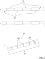
- Fig. 1a, 1b and 1c show a first embodiment 10 of a wire 11 with varying cross-section in a top view, side view and perspective view, respectively. In fact, it shows a delimited portion of the wire, depicting the alternating deformed and un-deformed sections of the wire.
- Fig. 1 shows at the same time the result of an embodiment of a method according to the invention.
- the wire 11 is initially a commercially available insulated wire.
- the cross-section of the wire and its insulation, seen as one entity, can be square as shown with the wire 11 in Fig. 1a .
- the cross-section can also be rounded and especially a circle.
- the forming tool 300 will be described later on in connection with Fig. 12 and 13 showing one embodiment how to create a deformed wire 311.
- the initial wire 310 can be rectangular or oblong/elliptical, especially it can be an initial wire which is insulated.
- the cross-section of the deformed section 13 of Fig. 13 as well as of Fig. 1 is flatter and wider than the original section 12.
- deformed upper shoulders 101 and side shoulders 102 are present between the sections 12 and 13, mainly comprising inclined surfaces between the corresponding adjacent surfaces. Adjacent shoulders 101 and 102 have opposite oriented inclinations. In case of a rounded wire 11 (not shown in the drawings), the shoulders are more complex tridimensional curves.
- Fig. 2A, 2b and 2c show a second embodiment 20 of a wire with varying cross-section in a top view, a side view and a perspective view, respectively.
- the wire 21 is a commercially available insulated wire.
- the wire 21's cross-section is uniform throughout its length. As the wire 21 is wound onto the magnet core, it is periodically deformed such that untouched areas 22 having substantially the original cross-section alternate with deformed areas 23 having a new cross-section.
- the cross-section of the deformed section 23 is both flatter and narrower than the original section 22, i.e. it is compressed to a smaller cross-section area.
- the tool used to deform the wire 21 deforms the wire 21 along both its height and width.
- upper shoulders 201 and side shoulders 202 mainly comprising inclined surfaces between the corresponding adjacent surfaces.
- Adjacent shoulders 201 and 202 have an inclination directed into the same direction, i.e. reducing the cross-sectional area from a section 22 to a section 23 and increasing the cross-sectional area from section 23 to section 22.
- Fig. 3 is a side view of a portion of one layer of a wire embodiment 10 where wire 11 is wrapped around a cylindrical magnet core 15. It is clear that axial channels 16 will be formed between the wire 11 and the core's 15 surface, as well as between subsequent winding layers (not shown in Fig. 3 ). Similar channels will also be formed, if an embodiment according to Fig. 3 is provided with the wire 20 of Fig. 2 .
- Fig. 4 is a top view on a portion of four adjacent windings or turns 19 of one layer 29 of a coil formed from the wire 11 of the wire embodiment 10 depicted in Fig. 1 , wherein the wire parameters in connection with the core (not shown) are chosen such that the deformed sections 13 in adjacent windings are aligned. Of course, the undeformed sections 12 are then aligned as well. The deformed sections 13 are aligned with each other, forming clearly defined radial coolant channels 110, whereas the side surfaces of the adjacent undeformed sections 12 are touching one the other at contact surfaces 111.
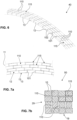
- Fig. 5 is a perspective view of the four aligned windings 19 of one single layer 29 of Fig. 4 , wherein both axial coolant channels 115 and radial coolant channels 110 are visible.
- Fig. 6 is a perspective view of portions of four adjacent windings 19 of one layer 29 of a coil formed from the wire depicted in Fig 1 , wherein the adjacent deformed sections 13 are not aligned. In this case, of course, the undeformed sections 12 are not aligned as well in adjacent layers. Still, it is clear that both axial 115 and radial 110 coolant channels will emerge.
- Fig. 7a is a top view of a 4x4 portion of a coil with four adjacent windings 19 in four layers 29 formed from the wire embodiment 10 depicted in Fig. 1 wherein the alignment of coolant channels 110 and 115 is not controlled and Fig. 7b is a cross-sectional view of the 4x4 portion of Fig. 7a showing that the channels 110 and 115 are allowed to form stochastically, since the alignment of the deformed sections 13 of the wire 11 is entirely random.
- the 4x4 array is chosen to illustrate the emerging cooling channels 110 and 115. In a typical application both the actual number of windings per layer and as well as the actual number of layers can be many times larger, e.g. especially between 10 and 100 layers 29 with between 10 and 500 windings or turns 19.
- the use of a 4 times 4 array of windings and layers has been chosen to illustrate the applying principles, it could be understood to show a detail of a larger coil.
- Fig. 8 is a perspective view of a 4x4 portion of a coil formed from the wire embodiment 10 depicted in Fig. 1 wherein four adjacent windings 19 are aligned, forming well-defined coolant channels in both the axial and radial directions.
- the alignment within the array of wires of adjacent windings is controlled such that the deformed sections 13 align throughout winding layers 29.
- the channels in both the radial and axial directions are clearly marked with reference numerals 110 and 115, respectively.
- the hatched surfaces are representing the deformed surface of the smaller dimension.
- Fig. 9 is a schematic cross-sectional view of a first embodiment of an electromagnetic coil 70 having a permeable winding 72 wherein the coolant flow is primarily axial as represented through the arrows with the reference numerals 211.
- the first magnet embodiment 70 has a permeable winding 72 wound around a magnet core 71. Winding 72 is shown as filling up the room between core 71, end caps 75, 76 as well as outer tube 77; but of course, winding 72 is built from a plurality of wire windings in a plurality of wire layers as shown in Fig. 8 with wires 10 or 20 from Fig. 1 or 2 or similar embodiments.
- End caps 75 and 76 form the structural support for the winding, and together with outer tube 77 form a sealed volume around winding 72.
- Coolant is pumped as represented by inlet flow 200 through inlet(s) 73 in the endcap 75 and out through outlet(s) 74 in the endcap 76 as outlet flow 212. As the coolant enters the winding, it disperses radially and flows axially as axial flow 211 to outlet 74.
- inlet 73 and outlet 74 are on the same side of the magnet 71 by either segmenting the wire volume to form a U-shaped flow path that returns to the inlet side or by embedding flow channels to lead the coolant back to the inlet side at endcap 75 either through the core 71 or around the winding.
- Fig. 10 is a schematic cross-sectional view of a further embodiment of an electromagnetic coil 80 having a permeable winding wherein the coolant flow 213 is primarily radial.
- the second magnet embodiment 80 comprises a permeable winding 82 wound around a magnet core 81. Endcaps 85 and 86, together with outer tube 87 form a sealed volume around winding 82. Winding 82 shown as plain surface between elements 81, 85, 86 and 87 is as in Fig. 9 built from a plurality of wire windings in a plurality of layers. Coolant is pumped through inlet(s) 83 and through radial cooling channels 88' in core 81.
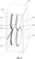
- Fig. 11 is a schematic perspective view of parts of a wire forming apparatus
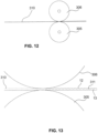
- Fig. 12 is a schematic side-view of the forming wheels305 and 306 of the apparatus of Fig. 11 with a wire
- Fig. 13 is a schematic enlarged view of Fig. 12
- the winding tool 300 as shown in the schematic perspective view of the main parts in Fig. 13 comprises a set of two forming wheels 305 and 306 having a pattern of ridges 308 on their outer surface.
- the initial preferably insulated wire 310 may be drawn through the forming wheels 305 and 306 passively or the wheels may be driven actively by means of a drive shaft 301.
- a synchronization mechanism presented here as two meshing gears 304 ensures that the forming wheels 305 and 306 rotate together and do not become out of sync.
- One of the meshing gears 304 is mounted on the driving shaft 301 whereas the second of the meshing gears 304 is mounted on an upper axle302.
- the forming wheels 305 and 306 are mounted in parallel onto these axles 301 and 302, respectively.
- Fig. 14 is a perspective view on a portion of a third embodiment of the wire 140, depicting the alternating deformed and un-deformed portions of the wire 140.
- the wire 140 has a round circular form in the undeformed wire portions 120.
- the deformed wire portions 130 are delimited in the drawing of Fig. 14 by a line indicating a gradually rounded recess without an edge.
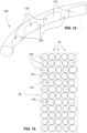
- Fig. 15 is a cross sectional view on a 5x12 portion of a coil with five adjacent windings or turns 19 in twelve layers 29 formed from the wire 140 depicted in Fig. 14 wherein the alignment of coolant channels 110 and 116 is only controlled over the different layers.
- Reference numerals 140 in Fig. 15 indicate towards three different wires 140; one wire 140 with a round circular cross section (indicated with a crosshair) and two oval or elliptic wires 140 having the largest diameter in two directions one perpendicular to the other.
- Arrow 19 indicate the adjacent turns, here five turns 19.
- radial coolant channels 110 there are a plurality of radial coolant channels 110.
- cross-section coolant channels 116 at the intersection of two adjacent turns 19 of wires 140 of two adjacent layers 29.
- the number of adjacent turns 19 can be chosen in all embodiments from several to 10 or more
- the number of adjacent layers 29 can be chosen in all embodiments from several to 10 or 100 or more, creating arrays of e.g. 10 times 100 wires 140 (or wires 10 or wires 20).
- Fig. 16 is a perspective view of a 3x5 portion of a coil formed from the wire 140 depicted in Fig. 14 wherein adjacent windings are aligned, forming well-defined axial coolant channels 115 and cross-section coolant channels 116.
- adjacent windings of wires 140 in turns 19 are touching each other, but between different layers there appear axial coolant channels 115.
- cross-section coolant channels 116 at the intersections.
Landscapes
- Engineering & Computer Science (AREA)
- Power Engineering (AREA)
- Manufacturing & Machinery (AREA)
- Coils Of Transformers For General Uses (AREA)
- Windings For Motors And Generators (AREA)
- Magnetic Resonance Imaging Apparatus (AREA)
Description
- The present invention relates to an electro-magnetic coil with coolant permeability.
- Electromagnetic coils are a basic component of a vast array of modern technologies. High-power electromagnetic coils in particular are used extensively in the fields of medicine, particle physics, micromanipulation, and many others. Such coils comprise electromagnetic coil windings that are often actively cooled with a fluid to allow the winding to withstand high current density without overheating.
- Various strategies exist to make this cooling maximally effective. Generally speaking, it is advantageous to increase the rate of coolant flow and the area of the wire in contact with the coolant, while at the same time maximizing proximity of wire and coolant, i.e. any heat conducted to the coolant should have to traverse as short a distance through the wire as possible. Also, it is of course preferable to use standard wires and winding techniques if possible.
- A number of designs and configurations for electromagnetic coil windings have been proposed in the literature, the most relevant of which are described here.
-
US 2,710,947 describes a coil wound with two strips of material simultaneously - the first being an un-insulated conductor, and the second being a corrugated insulator - such that the corrugated insulating strip forms axial cooling channels in the coil structure. -
EP 2,330,603 describes a transformer coil wound with two conductive strips, at least one of which is corrugated in order to form axially-extending coolant channels. -
US 8,284,006 describes an air-cooled transformer coil having spacer elements between winding layers that form axial passages for air to flow. - Many different approaches to create cooling channels by embedding different spacer elements within the winding are known. One example is
US 7,023,312 disclosing thermoplastic ducts spaced between the layers of conductive winding. -
US 3,579,162 describes a transformer coil having axial cooling ducts around which the coil wires are wound. -
US 2,632,041 describes a transformer having winding sections separated by axial spacer elements, thus forming radial cooling channels. -
US 3,056,071 describes an electromagnetic coil formed with a wire having shallow groove-shaped cutouts that form axial cooling channels. -
DE 889 649 C discloses an electro-magnetic coil according to the preamble of claim 1. - The electro-magnetic coils described in the prior art require complex wire geometries and/or winding techniques.
- In light of the aforementioned prior art and the limitations thereof, it is inter alia an object of this invention to provide a coil whose coolant permeability emerges intrinsically.
- An electro-magnetic coil with coolant permeability according to the invention is wound using insulated wire, comprising a plurality of radially arranged layers and a plurality of axially arranged turns of the insulated wire per layer, wherein the insulated wire has a plurality of sections along its length with different cross-sections for any pair of two adjacent sections such that the empty spaces formed by the axially- and radially-adjacent cross-sections of insulated wire collectively form coolant channels.
- A coil according to the invention comprises a coil whose coolant permeability emerges intrinsically as a result of the wire's varying cross-sectional shape. The difference of the cross-section of adjacent section can comprise a variation of height or a variation of width or a variation of both dimensions. Such an embodiment according to the invention is characterized by combined axial and radial cooling channels providing a coil winding with coolant permeability in both the axial and radial directions.
- Such a coolant permeable coil can be formed from standard, readily available insulated wires using common coil winding techniques.
- A coil can be wound from a wire having periodically varying cross-sectional shape and/or area along its length. This wire can be formed by drawing a standard insulated wire with uniform cross-section through a forming tool, which periodically compresses sections of the wire along its height, width or both. As the wire is wound in multiple rows over multiple layers, the varying cross-sections form coolant channels in both axial and radial directions. The shape and periodicity of the cross-sections can be optimized for various purposes. For instance, if it was advantageous for the majority of coolant to flow in the radial direction, the cross-sectional parameters of the wire could be adjusted to form primarily radial coolant channels, and vice versa.
- The coil according to the invention results in a large heat transfer area with coolant distributed throughout the winding volume. It does not require separate spacer elements which simplifies the winding process and allows maximal packing density (volume copper / total volume) to achieve maximum magnetic field generation per given input power. The optimization is related to both the coil itself and the method of winding it. The fact that it does not require spacers and can be wound using standard practices is related to the method, but the realization of optimal packing density is a property of the winding configuration itself, regardless of how it is actually achieved.
- The coil preferably comprises a housing with at least one inlet and at least one outlet, connected to gaps in axial and/or radial directions of the coil creating channels for a coolant fluid, wherein the inlet(s) and outlet(s) are adapted to be connected to a coolant circuit to pump a coolant fluid through the channels of the coil to cool the coil.
- The inlet(s) and outlet(s) can be provided in longitudinal direction at opposite sides of the housing of the coil, e.g. at the same radial direction from the core of the coil, wherein the coolant is moved through the winding in axial direction by applying an axial pressure gradient and the radial cooling channels are used to distribute flow evenly over radial flow cross-section.
- The inlet(s) and outlet(s) can also be provided in different radial distances from the core of the coil, then the coolant is moved through the winding in radial direction (inward or outward) by applying a radial pressure gradient and the axial cooling channels are used to distribute flow evenly over axial flow cross-section.
- According to another embodiment, a relationship between the wire parameters and the resulting coil is defined beforehand that ensure the channels will continue to align with themselves over multiple layers, in order to realize an ideal channel configuration. One such relationship comprises in its simplest form to set L = 2*pi*t, where L is the length of the periodic pattern, and t is the maximum thickness (height) of the wire, with pi being Ludolph's number. At the same time the circumference of the core on which the wire is wound is chosen to be a multiple of length L so that deformed and un-deformed sections between windings in the same layer align. In other words L is a divisor of the value of the circumference of the core on which the wire is wound. This alignment is still essentially achieved for a high number of layers increasing the diameter of the wound wire layers.
- The coolant channels can be formed from the group encompassing radial coolant channels between subsequent layers of wires, axial coolant channels between adjacent turns of wires, and cross-section coolant channels between two adjacent turns and between two subsequent layers.
- The cross-section of the wire can change between undeformed circular sections and two different deformed section, i.e. oval or elliptic sections with the longer axis direction in either layer or turn orientation.
the wire using a wire-forming tool consisting in one embodiment of two wheels that have profiled surfaces corresponding to the desired wire thickness. - This method allows winding a coil from a single, continuous, insulated wire in traditional manner, but without requiring the use of additional spacing elements. The deformation process of an ordinary insulated wire takes place at the same time as winding by pressing and deforming the wire right before winding it.
- According to one embodiment, the parameters of the wire taken from the group including thickness, deformation periodicity, deformed section length, deformed section width and inner diameter of the winding are chosen at random. This allows creating coolant channels which form stochastically. While the resultant channels will still be very effective, they will likely not be optimal.
- According to another embodiment, a relationship between the wire parameters and the resulting coil is defined beforehand that ensure the channels will continue to align with themselves over multiple layers, in order to realize an ideal channel configuration. One such relationship comprises in its simplest form to set L = 2*pi*t, where L is the length of the periodic pattern, and t is the maximum thickness (height) of the wire, with pi being Ludolph's number. At the same time the circumference of the core on which the wire is wound is chosen to be a multiple of length L so that deformed and un-deformed sections between windings in the same layer align. In other words L is a divisor of the value of the circumference of the core on which the wire is wound. This alignment is still essentially achieved for a high number of layers increasing the diameter of the wound wire layers.
- The coolant channels can be formed from the group encompassing radial coolant channels between subsequent layers of wires, axial coolant channels between adjacent turns of wires, and cross-section coolant channels between two adjacent turns and between two subsequent layers.
- The cross-section of the wire can change between undeformed circular sections and two different deformed section, i.e. oval or elliptic sections with the longer axis direction in either layer or turn orientation.
- An electromagnetic coil winding according to the invention has intrinsically emerging radial and axial coolant channels. The coil is wound from a wire with varying cross-sectional shape, said wire consisting of alternating deformed and undeformed sections that collectively form into axial and radial coolant channels as the wire is wound around a core.
- Preferred embodiments of the invention are described in the following with reference to the drawings, which are for the purpose of illustrating the present preferred embodiments of the invention and not for the purpose of limiting the same. In the drawings,
- Fig. 1a
- is a top view on a portion of a first embodiment of the wire, depicting the alternating deformed and un-deformed portions of the wire,
- Fig. 1b
- is a side view of the wire according to
Fig. 1a , - Fig. 1c
- is a perspective view of the wire according to
Fig. 1a , - Fig. 2a
- is a top view on a portion of a second embodiment of the wire, depicting the alternating deformed and un-deformed sections of the wire,
- Fig. 2b
- is a side view of the wire according to
Fig. 2a , - Fig. 2c
- is a perspective view of the wire according to
Fig. 2a , - Fig. 3
- is a side view on a portion of one layer of the wire from
Fig. 1 wrapped around a cylindrical core, - Fig. 4
- is a top view on a portion of four adjacent windings of one layer of a coil formed from the wire depicted in
Fig. 1 , wherein the wire parameters are chosen such that the deformed sections in adjacent windings are aligned, - Fig. 5
- is a perspective view of the four aligned windings of
Fig. 4 , - Fig. 6
- is a perspective view on portions of four adjacent windings of one layer of a coil formed from the wire depicted in
Fig 1 , wherein the adjacent deformed sections are not aligned, - Fig. 7a
- is a top view on a 4x4 portion of a coil with four adjacent windings in four layers formed from the wire depicted in
Fig. 1 wherein the alignment of coolant channels is not controlled, - Fig. 7b
- is a cross-sectional view of the 4x4 portion of
Fig. 7A showing that the channels are allowed to form stochastically, - Fig. 8
- is a perspective view of a 4x4 portion of a coil formed from the wire depicted in
Fig. 1 wherein adjacent windings are aligned, forming well-defined coolant channels in both the axial and radial directions, - Fig. 9
- is a schematic cross-sectional view of a first embodiment of an electromagnetic coil having a permeable winding wherein the coolant flow is primarily axial,
- Fig. 10
- is a schematic cross-sectional view of a further embodiment of an electromagnetic coil having a permeable winding wherein the coolant flow is primarily radial,
- Fig. 11
- is a schematic perspective view of parts of a wire forming apparatus,
- Fig. 12
- is a schematic side-view of the forming wheels of the apparatus of
Fig. 11 with a wire, - Fig. 13
- is a schematic enlarged view of
Fig. 12 ; - Fig. 14
- is a perspective view on a portion of a third embodiment of the wire, depicting the alternating deformed and un-deformed portions of the wire;
- Fig. 15
- is a cross sectional view on a 5x12 portion of a coil with five adjacent windings in nine layers formed from the wire depicted in
Fig. 14 wherein the alignment of coolant channels is only controlled over the different layers; and - Fig. 16
- is a perspective view of a 3x5 portion of a coil formed from the wire depicted in
Fig. 14 wherein adjacent windings are aligned, forming well-defined axial coolant channels and cross-section coolant channels. -
Fig. 1a, 1b and 1c show afirst embodiment 10 of awire 11 with varying cross-section in a top view, side view and perspective view, respectively. In fact, it shows a delimited portion of the wire, depicting the alternating deformed and un-deformed sections of the wire. -
Fig. 1 shows at the same time the result of an embodiment of a method according to the invention. Thewire 11 is initially a commercially available insulated wire. At first the wire's 11 cross-section is uniform throughout its length. The cross-section of the wire and its insulation, seen as one entity, can be square as shown with thewire 11 inFig. 1a . The cross-section can also be rounded and especially a circle. As thewire 11 is wound onto the magnet core forming a coil, it is passed through a formingtool 300 as shown inFig. 11 , periodically deforming sections of thewire 11 such thatuntouched areas 12 having the original cross-section (e.g. square or circular or a minimally deformed cross-section) alternate withdeformed areas 13 having a new cross-section. The formingtool 300 will be described later on in connection withFig. 12 and 13 showing one embodiment how to create adeformed wire 311. - The
initial wire 310 can be rectangular or oblong/elliptical, especially it can be an initial wire which is insulated. The cross-section of thedeformed section 13 ofFig. 13 as well as ofFig. 1 is flatter and wider than theoriginal section 12. Between thesections upper shoulders 101 andside shoulders 102, mainly comprising inclined surfaces between the corresponding adjacent surfaces.Adjacent shoulders - Of course it is possible to start with a
wire 11 having a rectangular cross-section and deform it into an essentially square one. The deformation process is not intended to damage the insulation. It is possible that the main part of the deformation is exerted within the insulation coating. -
Fig. 2A, 2b and 2c show asecond embodiment 20 of a wire with varying cross-section in a top view, a side view and a perspective view, respectively. Thewire 21 is a commercially available insulated wire. At first thewire 21's cross-section is uniform throughout its length. As thewire 21 is wound onto the magnet core, it is periodically deformed such thatuntouched areas 22 having substantially the original cross-section alternate withdeformed areas 23 having a new cross-section. The cross-section of thedeformed section 23 is both flatter and narrower than theoriginal section 22, i.e. it is compressed to a smaller cross-section area. In other words, the tool used to deform thewire 21 deforms thewire 21 along both its height and width. - Between the
sections upper shoulders 201 andside shoulders 202, mainly comprising inclined surfaces between the corresponding adjacent surfaces.Adjacent shoulders section 22 to asection 23 and increasing the cross-sectional area fromsection 23 tosection 22. -
Fig. 3 is a side view of a portion of one layer of awire embodiment 10 wherewire 11 is wrapped around acylindrical magnet core 15. It is clear thataxial channels 16 will be formed between thewire 11 and the core's 15 surface, as well as between subsequent winding layers (not shown inFig. 3 ). Similar channels will also be formed, if an embodiment according toFig. 3 is provided with thewire 20 ofFig. 2 . -
Fig. 4 is a top view on a portion of four adjacent windings or turns 19 of onelayer 29 of a coil formed from thewire 11 of thewire embodiment 10 depicted inFig. 1 , wherein the wire parameters in connection with the core (not shown) are chosen such that thedeformed sections 13 in adjacent windings are aligned. Of course, theundeformed sections 12 are then aligned as well. Thedeformed sections 13 are aligned with each other, forming clearly definedradial coolant channels 110, whereas the side surfaces of the adjacentundeformed sections 12 are touching one the other at contact surfaces 111. - When a second layer of windings (here four turns 19) is arranged on the
first layer 29 shown inFig. 4 , then further contactsurfaces 111 are built on the top surfaces of theundeformed sections 12, if the alignment is chosen that thedeformed section 13 of the subsequent layer is positioned with its longer portion of the cross-section as bottom surface on said top surface. -
Fig. 5 is a perspective view of the four alignedwindings 19 of onesingle layer 29 ofFig. 4 , wherein bothaxial coolant channels 115 andradial coolant channels 110 are visible. -
Fig. 6 is a perspective view of portions of fouradjacent windings 19 of onelayer 29 of a coil formed from the wire depicted inFig 1 , wherein the adjacentdeformed sections 13 are not aligned. In this case, of course, theundeformed sections 12 are not aligned as well in adjacent layers. Still, it is clear that both axial 115 and radial 110 coolant channels will emerge. -
Fig. 7a is a top view of a 4x4 portion of a coil with fouradjacent windings 19 in fourlayers 29 formed from thewire embodiment 10 depicted inFig. 1 wherein the alignment ofcoolant channels Fig. 7b is a cross-sectional view of the 4x4 portion ofFig. 7a showing that thechannels deformed sections 13 of thewire 11 is entirely random. The 4x4 array is chosen to illustrate the emergingcooling channels layers 29 with between 10 and 500 windings or turns 19. The use of a 4 times 4 array of windings and layers has been chosen to illustrate the applying principles, it could be understood to show a detail of a larger coil. -
Fig. 8 is a perspective view of a 4x4 portion of a coil formed from thewire embodiment 10 depicted inFig. 1 wherein fouradjacent windings 19 are aligned, forming well-defined coolant channels in both the axial and radial directions. The alignment within the array of wires of adjacent windings is controlled such that thedeformed sections 13 align throughout winding layers 29. The channels in both the radial and axial directions are clearly marked withreference numerals -
Fig. 9 is a schematic cross-sectional view of a first embodiment of anelectromagnetic coil 70 having a permeable winding 72 wherein the coolant flow is primarily axial as represented through the arrows with thereference numerals 211. Thefirst magnet embodiment 70 has a permeable winding 72 wound around amagnet core 71. Winding 72 is shown as filling up the room betweencore 71, end caps 75, 76 as well asouter tube 77; but of course, winding 72 is built from a plurality of wire windings in a plurality of wire layers as shown inFig. 8 withwires Fig. 1 or2 or similar embodiments. - End caps 75 and 76 form the structural support for the winding, and together with
outer tube 77 form a sealed volume around winding 72. Coolant is pumped as represented byinlet flow 200 through inlet(s) 73 in theendcap 75 and out through outlet(s) 74 in theendcap 76 asoutlet flow 212. As the coolant enters the winding, it disperses radially and flows axially asaxial flow 211 tooutlet 74. Variations of the design are possible such as whereinlet 73 andoutlet 74 are on the same side of themagnet 71 by either segmenting the wire volume to form a U-shaped flow path that returns to the inlet side or by embedding flow channels to lead the coolant back to the inlet side atendcap 75 either through the core 71 or around the winding. -
Fig. 10 is a schematic cross-sectional view of a further embodiment of anelectromagnetic coil 80 having a permeable winding wherein thecoolant flow 213 is primarily radial. Thesecond magnet embodiment 80 comprises a permeable winding 82 wound around amagnet core 81. Endcaps 85 and 86, together withouter tube 87 form a sealed volume around winding 82. Winding 82 shown as plain surface betweenelements Fig. 9 built from a plurality of wire windings in a plurality of layers. Coolant is pumped through inlet(s) 83 and through radial cooling channels 88' incore 81. As the coolant leaves thecore 81 and enters the winding 82, it disperses axially and flows radially into groove(s) 89 which are cut intoouter tube 87 and which lead in a redirectedaxial coolant flow 214 to outlet(s) 84 inend cap 86. -
Fig. 11 is a schematic perspective view of parts of a wire forming apparatus,Fig. 12 is a schematic side-view of the forming wheels305 and 306 of the apparatus ofFig. 11 with a wire, andFig. 13 is a schematic enlarged view ofFig. 12 . In an embodiment, the windingtool 300 as shown in the schematic perspective view of the main parts inFig. 13 comprises a set of two formingwheels ridges 308 on their outer surface. The initial preferably insulatedwire 310 may be drawn through the formingwheels drive shaft 301. As thewire 310 passes through the formingwheels ridges 308 on thewheels gears 304 ensures that the formingwheels shaft 301 whereas the second of the meshing gears 304 is mounted on an upper axle302. The formingwheels axles -
Fig. 14 is a perspective view on a portion of a third embodiment of thewire 140, depicting the alternating deformed and un-deformed portions of thewire 140. Thewire 140 has a round circular form in theundeformed wire portions 120. Thedeformed wire portions 130 are delimited in the drawing ofFig. 14 by a line indicating a gradually rounded recess without an edge. -
Fig. 15 is a cross sectional view on a 5x12 portion of a coil with five adjacent windings or turns 19 in twelvelayers 29 formed from thewire 140 depicted inFig. 14 wherein the alignment ofcoolant channels Reference numerals 140 inFig. 15 indicate towards threedifferent wires 140; onewire 140 with a round circular cross section (indicated with a crosshair) and two oval orelliptic wires 140 having the largest diameter in two directions one perpendicular to the other.Arrow 19 indicate the adjacent turns, here five turns 19. There are twelvelayers 29. In the embodiment ofFig. 15 every subsequent layer is directly contacting the more inner layer so that there are noaxial coolant channels 115. However, there are a plurality ofradial coolant channels 110. In view of theround wires 140 changing their cross-section from circular to elliptic or oval in the two perpendicular directions, there appearcross-section coolant channels 116 at the intersection of twoadjacent turns 19 ofwires 140 of twoadjacent layers 29. The number ofadjacent turns 19 can be chosen in all embodiments from several to 10 or more The number ofadjacent layers 29 can be chosen in all embodiments from several to 10 or 100 or more, creating arrays of e.g. 10 times 100 wires 140 (orwires 10 or wires 20). - Finally,
Fig. 16 is a perspective view of a 3x5 portion of a coil formed from thewire 140 depicted inFig. 14 wherein adjacent windings are aligned, forming well-definedaxial coolant channels 115 andcross-section coolant channels 116. In other words, here, the adjacent windings ofwires 140 inturns 19 are touching each other, but between different layers there appearaxial coolant channels 115. In any case, in view of theround wires 140 there arecross-section coolant channels 116 at the intersections. -
10 wire (first embodiment) 87 outer tube 11 wire 88 axial core coolant channel 12 undeformed wire sections 88' radial core coolant channel 13 deformed wire sections 89 grooved coolant channel 15 core 101 defor. upper/ lower shoulder 16 axial channel 102 deformed side shoulder 19 turn 110 radial coolant channel 20 wire (second embodiment) 111 contact surface 21 wire 115 axial coolant channel 22 undeformed wire sections 116 cross-section coolant channel 23 deformed wire sections 120 undeformed wire sections 29 layer 130 deformed wire sections 30 first winding embodiment 131 depression 40 second winding embodiment 140 wire (third embodiment) 50 third winding embodiment 200 inlet flow 60 fourth winding embodiment 201 defor. upper/ lower shoulder 70 first magnet embodiment 202 deformed side shoulder 71 magnet core 211 axial coolant flow 72 permeable winding 212 outlet flow 73 coolant inlet 213 radial coolant flow 74 coolant outlet 214 axial coolant flow 75 first endcap 300 forming apparatus 76 second endcap 301 driven axle 77 outer tube 302 second axle 80 second magnet embodiment 304 driving gears 81 magnet core 305 lower forming wheel 82 permeable winding 306 upper forming wheel 83 coolant inlet 308 ridge pattern 84 coolant outlet 310 unformed wire 85 first endcap 311 formed wire 86 second endcap
Claims (10)
- An electro-magnetic coil (60, 70, 80) with coolant permeability wound using insulated wire (11, 21), comprising a plurality of radially arranged layers (29) and a plurality of axially arranged turns (19) of the insulated wire (11, 21) per layer (29), characterized in that the insulated wire (11, 21) has a plurality of sections (12, 13; 22, 23) along its length with different cross-sections for any pair of two adjacent sections (12 to 13; 22 to 23) such that the empty spaces formed by the axially- and radially-adjacent cross-sections of insulated wire collectively form coolant channels (110, 115, 116).
- The coil according to claim 1, wherein the difference of the cross-section comprises a variation of height or a variation of width or a variation of both dimensions.
- The coil according to claim 1 or claim 2, so that the coil comprises a housing (75, 76, 77; 85, 86, 87) with at least on inlet (73; 83) and at least one outlet (74; 84), connected to gaps (88', 89) in axial (211) and/or radial (213) direction of the coil creating channels (110, 115) for a coolant fluid, wherein the inlet(s) (73; 83) and outlet(s) (74; 84) are adapted to be connected to a coolant circuit to pump a coolant fluid through the channels of the coil to cool the coil.
- The coil according to claim 3, wherein the coolant is moved through the winding in axial direction by applying an axial pressure gradient between the inlet(s) (73; 83) and outlet(s) (74; 84), optionally with a fluid pump, and the radial cooling channels (110) are used to distribute flow evenly over radial flow cross-section.
- The coil according to claim 3, wherein the coolant is moved through the winding in radial direction (inward or outward) by applying a radial pressure gradient between the inlet(s) (73; 83) and outlet(s) (74; 84), optionally with a fluid pump, and the axial cooling channels (115) are used to distribute flow evenly over axial flow cross-section.
- The coil according to any one of claims 1 to 4, wherein the local wire deformation of adjacent sections (12 to 13; 22 to 23) is not coordinated with the tangential position on the coil and gaps in axial and radial direction are created stochastically.
- The coil according to any one of claims 1 to 4, wherein the local wire deformation of adjacent sections (12 to 13; 22 to 23) is coordinated with the tangential position on the coil and cooling channels in axial and/or radial direction are created in a coordinated way.
- The coil according to claim 7, where l = 2*pi*t, where l is the length of the periodic pattern, and t is the maximum thickness of the wire (11, 21), with pi being Ludolph's number, wherein l is a divider of the circumference of the core (15) on which the wire (11, 21) is wound, so that deformed and un-deformed sections between windings in the same layer align.
- The coil according to any one of claims 1 to 8, wherein the coolant channels are from the group emcompassing radial coolant channels (110) between subsequent layers (29) of wires, axial coolant channels (115) between adjacent turns (19) of wires, and cross-section coolant channels (116) between two adjacent turns (19) and between two subsequent layers (29).
- The coil according to any one of claims 1 to 8, wherein the cross-section of the wire (140) changes between undeformed circular sections (120) and oval or elliptic sections (130) with the longer axis direction in layer or turn direction.
Applications Claiming Priority (1)
| Application Number | Priority Date | Filing Date | Title |
|---|---|---|---|
| PCT/EP2020/052019 WO2021151468A1 (en) | 2020-01-28 | 2020-01-28 | Electro-magnetic coil with coolant permeability |
Publications (3)
| Publication Number | Publication Date |
|---|---|
| EP4097746A1 EP4097746A1 (en) | 2022-12-07 |
| EP4097746B1 true EP4097746B1 (en) | 2024-10-02 |
| EP4097746C0 EP4097746C0 (en) | 2024-10-02 |
Family
ID=69374302
Family Applications (1)
| Application Number | Title | Priority Date | Filing Date |
|---|---|---|---|
| EP20702454.8A Active EP4097746B1 (en) | 2020-01-28 | 2020-01-28 | Electro-magnetic coil with coolant permeability |
Country Status (7)
| Country | Link |
|---|---|
| US (1) | US20230054802A1 (en) |
| EP (1) | EP4097746B1 (en) |
| JP (1) | JP7520148B2 (en) |
| KR (1) | KR102769688B1 (en) |
| CN (1) | CN115335929A (en) |
| ES (1) | ES2992161T3 (en) |
| WO (1) | WO2021151468A1 (en) |
Families Citing this family (1)
| Publication number | Priority date | Publication date | Assignee | Title |
|---|---|---|---|---|
| US20240009430A1 (en) * | 2022-07-08 | 2024-01-11 | Abbott Cardiovascular Systems Inc. | Guidewire core having non-round cross-sections |
Family Cites Families (20)
| Publication number | Priority date | Publication date | Assignee | Title |
|---|---|---|---|---|
| US2632041A (en) | 1950-02-11 | 1953-03-17 | Gen Electric | Transformer cooling duct construction |
| DE889649C (en) * | 1951-09-27 | 1953-09-14 | Siemens Ag | Arrangement on coils of electrical machines or apparatus with regularly wound conductors arranged in a concentrated winding space |
| US2710947A (en) | 1951-11-28 | 1955-06-14 | Electrocraft Company | Electrical coil construction |
| US2917701A (en) * | 1957-08-02 | 1959-12-15 | Mc Graw Edison Co | Forced-cooled transformer having winding temperature relay |
| US3056071A (en) | 1959-02-12 | 1962-09-25 | William R Baker | Electrical coil structure |
| US3170134A (en) * | 1961-12-15 | 1965-02-16 | Westinghouse Electric Corp | Electrical coil structure for inductive apparatus |
| US3579162A (en) | 1969-11-28 | 1971-05-18 | Gen Electric | Winding duct construction for power transformer |
| US3781739A (en) * | 1973-03-28 | 1973-12-25 | Westinghouse Electric Corp | Interleaved winding for electrical inductive apparatus |
| US4239077A (en) * | 1978-12-01 | 1980-12-16 | Westinghouse Electric Corp. | Method of making heat curable adhesive coated insulation for transformers |
| JPH1126253A (en) * | 1997-07-07 | 1999-01-29 | Hitachi Ltd | Coil and conductor for electrical equipment |
| DE10127556A1 (en) * | 2001-06-06 | 2002-12-12 | Nexans France S A | Metallic wire |
| US7023312B1 (en) | 2001-12-21 | 2006-04-04 | Abb Technology Ag | Integrated cooling duct for resin-encapsulated distribution transformer coils |
| KR20060079148A (en) * | 2006-03-22 | 2006-07-05 | 임성황 | Transformer hollow winding chiller using refrigeration cycle |
| US7928626B2 (en) * | 2006-04-28 | 2011-04-19 | Mitsubishi Cable Industries, Ltd. | Linear material and stator structure |
| JP4431131B2 (en) * | 2006-10-24 | 2010-03-10 | 株式会社モステック | Wire rod and method of manufacturing the wire rod |
| PL2068426T3 (en) * | 2007-09-25 | 2017-09-29 | Essex Europe Sas | Electric coil conductor with rectangular cross-section |
| DE102008031746A1 (en) * | 2008-07-04 | 2010-01-07 | Abb Ag | Winding i.e. band winding, for e.g. cast resin transformer, has hollow spaces provided as cooling channels, arranged along respective winding layers of winding conductor, and formed by wave shaped parts of winding conductor |
| EP2330603A1 (en) | 2009-12-04 | 2011-06-08 | ABB Technology AG | Transformer with tape coil |
| US8284006B2 (en) | 2010-04-14 | 2012-10-09 | Southern Transformers & Magnetics, Llc | Passive air cooling of a dry-type electrical transformer |
| EP3131104B1 (en) * | 2015-08-14 | 2019-12-25 | ABB Schweiz AG | Cooling of a static electric induction system |
-
2020
- 2020-01-28 ES ES20702454T patent/ES2992161T3/en active Active
- 2020-01-28 EP EP20702454.8A patent/EP4097746B1/en active Active
- 2020-01-28 CN CN202080099051.8A patent/CN115335929A/en active Pending
- 2020-01-28 WO PCT/EP2020/052019 patent/WO2021151468A1/en not_active Ceased
- 2020-01-28 JP JP2022570752A patent/JP7520148B2/en active Active
- 2020-01-28 US US17/795,984 patent/US20230054802A1/en active Pending
- 2020-01-28 KR KR1020227029622A patent/KR102769688B1/en active Active
Also Published As
| Publication number | Publication date |
|---|---|
| KR102769688B1 (en) | 2025-02-17 |
| WO2021151468A1 (en) | 2021-08-05 |
| EP4097746A1 (en) | 2022-12-07 |
| US20230054802A1 (en) | 2023-02-23 |
| CN115335929A (en) | 2022-11-11 |
| ES2992161T3 (en) | 2024-12-09 |
| EP4097746C0 (en) | 2024-10-02 |
| KR20220129636A (en) | 2022-09-23 |
| JP2023517776A (en) | 2023-04-26 |
| JP7520148B2 (en) | 2024-07-22 |
Similar Documents
| Publication | Publication Date | Title |
|---|---|---|
| US5787567A (en) | Coil-forming wire material and method of manufacturing such material | |
| EP1129517B1 (en) | Method for producing a stator, stator and electric machine with this stator | |
| EP2362526B1 (en) | Method for manufacturing a stator for an energy converting apparatus | |
| WO2013023820A2 (en) | Winding carrier for use in an electrical machine and winding arrangement | |
| DE3334501A1 (en) | Method for producing laminated iron cores for electrical machines and apparatuses, and an arrangement of a laminated iron core produced according to said method | |
| WO1998018189A2 (en) | Electrical machine with a single pole winding | |
| CN101189779A (en) | Motor core components and motor components | |
| DE112015003443T5 (en) | Fluid cooled spiral strip structure | |
| JP5774082B2 (en) | Rotating electric machine | |
| JP3545390B2 (en) | Air-core coil, coil device, and manufacturing method thereof | |
| US7631413B2 (en) | Method of manufacturing of an armature winding for electro-mechanical machines | |
| CN106464100A (en) | Method for the production of an electric machine stator, comprising a pre-forming step, and corresponding wound stator | |
| US20230054802A1 (en) | Electro-Magnetic Coil with Coolant Permeability | |
| JPS5886836A (en) | Rotating electric machine and its manufacturing method | |
| DE102024115404A1 (en) | Winding for a stator for an electrical machine with first and second conductor devices | |
| US20150155749A1 (en) | Method of manufacturing a laminated winding and a laminated winding | |
| KR102171907B1 (en) | MSO Coil and Motor Having the Same | |
| US6483220B1 (en) | Precision-wound rotor for a dynamoelectric machine | |
| EP0160887B1 (en) | Device for enforced rotorwinding gas cooling of dynamoelectric machines, especially of turbogenerators | |
| JP4624334B2 (en) | Wire rod, wire manufacturing jig, and wire rod manufacturing method | |
| KR20170014616A (en) | Superconducting Wires and Manufacturing method thereof | |
| DE102013205240A1 (en) | Rotor or stator for an electric machine and method for its manufacture | |
| JP2003077737A (en) | Electrical equipment winding | |
| EP4152352B1 (en) | Coil | |
| EP4210076B1 (en) | Spacer element for a winding, kit, method for manufacturing a winding and winding |
Legal Events
| Date | Code | Title | Description |
|---|---|---|---|
| STAA | Information on the status of an ep patent application or granted ep patent |
Free format text: STATUS: UNKNOWN |
|
| STAA | Information on the status of an ep patent application or granted ep patent |
Free format text: STATUS: THE INTERNATIONAL PUBLICATION HAS BEEN MADE |
|
| PUAI | Public reference made under article 153(3) epc to a published international application that has entered the european phase |
Free format text: ORIGINAL CODE: 0009012 |
|
| STAA | Information on the status of an ep patent application or granted ep patent |
Free format text: STATUS: REQUEST FOR EXAMINATION WAS MADE |
|
| 17P | Request for examination filed |
Effective date: 20220727 |
|
| AK | Designated contracting states |
Kind code of ref document: A1 Designated state(s): AL AT BE BG CH CY CZ DE DK EE ES FI FR GB GR HR HU IE IS IT LI LT LU LV MC MK MT NL NO PL PT RO RS SE SI SK SM TR |
|
| DAV | Request for validation of the european patent (deleted) | ||
| DAX | Request for extension of the european patent (deleted) | ||
| GRAP | Despatch of communication of intention to grant a patent |
Free format text: ORIGINAL CODE: EPIDOSNIGR1 |
|
| STAA | Information on the status of an ep patent application or granted ep patent |
Free format text: STATUS: GRANT OF PATENT IS INTENDED |
|
| INTG | Intention to grant announced |
Effective date: 20240429 |
|
| GRAS | Grant fee paid |
Free format text: ORIGINAL CODE: EPIDOSNIGR3 |
|
| GRAA | (expected) grant |
Free format text: ORIGINAL CODE: 0009210 |
|
| STAA | Information on the status of an ep patent application or granted ep patent |
Free format text: STATUS: THE PATENT HAS BEEN GRANTED |
|
| AK | Designated contracting states |
Kind code of ref document: B1 Designated state(s): AL AT BE BG CH CY CZ DE DK EE ES FI FR GB GR HR HU IE IS IT LI LT LU LV MC MK MT NL NO PL PT RO RS SE SI SK SM TR |
|
| REG | Reference to a national code |
Ref country code: GB Ref legal event code: FG4D |
|
| REG | Reference to a national code |
Ref country code: CH Ref legal event code: EP |
|
| REG | Reference to a national code |
Ref country code: IE Ref legal event code: FG4D |
|
| REG | Reference to a national code |
Ref country code: DE Ref legal event code: R096 Ref document number: 602020038651 Country of ref document: DE |
|
| U01 | Request for unitary effect filed |
Effective date: 20241017 |
|
| U07 | Unitary effect registered |
Designated state(s): AT BE BG DE DK EE FI FR IT LT LU LV MT NL PT RO SE SI Effective date: 20241104 |
|
| REG | Reference to a national code |
Ref country code: ES Ref legal event code: FG2A Ref document number: 2992161 Country of ref document: ES Kind code of ref document: T3 Effective date: 20241209 |
|
| U20 | Renewal fee for the european patent with unitary effect paid |
Year of fee payment: 6 Effective date: 20250116 |
|
| PG25 | Lapsed in a contracting state [announced via postgrant information from national office to epo] |
Ref country code: HR Free format text: LAPSE BECAUSE OF FAILURE TO SUBMIT A TRANSLATION OF THE DESCRIPTION OR TO PAY THE FEE WITHIN THE PRESCRIBED TIME-LIMIT Effective date: 20241002 Ref country code: IS Free format text: LAPSE BECAUSE OF FAILURE TO SUBMIT A TRANSLATION OF THE DESCRIPTION OR TO PAY THE FEE WITHIN THE PRESCRIBED TIME-LIMIT Effective date: 20250202 |
|
| PG25 | Lapsed in a contracting state [announced via postgrant information from national office to epo] |
Ref country code: NO Free format text: LAPSE BECAUSE OF FAILURE TO SUBMIT A TRANSLATION OF THE DESCRIPTION OR TO PAY THE FEE WITHIN THE PRESCRIBED TIME-LIMIT Effective date: 20250102 |
|
| PG25 | Lapsed in a contracting state [announced via postgrant information from national office to epo] |
Ref country code: GR Free format text: LAPSE BECAUSE OF FAILURE TO SUBMIT A TRANSLATION OF THE DESCRIPTION OR TO PAY THE FEE WITHIN THE PRESCRIBED TIME-LIMIT Effective date: 20250103 |
|
| PG25 | Lapsed in a contracting state [announced via postgrant information from national office to epo] |
Ref country code: PL Free format text: LAPSE BECAUSE OF FAILURE TO SUBMIT A TRANSLATION OF THE DESCRIPTION OR TO PAY THE FEE WITHIN THE PRESCRIBED TIME-LIMIT Effective date: 20241002 Ref country code: CZ Free format text: LAPSE BECAUSE OF FAILURE TO SUBMIT A TRANSLATION OF THE DESCRIPTION OR TO PAY THE FEE WITHIN THE PRESCRIBED TIME-LIMIT Effective date: 20241002 |
|
| PG25 | Lapsed in a contracting state [announced via postgrant information from national office to epo] |
Ref country code: RS Free format text: LAPSE BECAUSE OF FAILURE TO SUBMIT A TRANSLATION OF THE DESCRIPTION OR TO PAY THE FEE WITHIN THE PRESCRIBED TIME-LIMIT Effective date: 20250102 |
|
| PG25 | Lapsed in a contracting state [announced via postgrant information from national office to epo] |
Ref country code: SM Free format text: LAPSE BECAUSE OF FAILURE TO SUBMIT A TRANSLATION OF THE DESCRIPTION OR TO PAY THE FEE WITHIN THE PRESCRIBED TIME-LIMIT Effective date: 20241002 |
|
| PG25 | Lapsed in a contracting state [announced via postgrant information from national office to epo] |
Ref country code: SK Free format text: LAPSE BECAUSE OF FAILURE TO SUBMIT A TRANSLATION OF THE DESCRIPTION OR TO PAY THE FEE WITHIN THE PRESCRIBED TIME-LIMIT Effective date: 20241002 |
|
| PLBE | No opposition filed within time limit |
Free format text: ORIGINAL CODE: 0009261 |
|
| STAA | Information on the status of an ep patent application or granted ep patent |
Free format text: STATUS: NO OPPOSITION FILED WITHIN TIME LIMIT |
|
| 26N | No opposition filed |
Effective date: 20250703 |
|
| PG25 | Lapsed in a contracting state [announced via postgrant information from national office to epo] |
Ref country code: MC Free format text: LAPSE BECAUSE OF FAILURE TO SUBMIT A TRANSLATION OF THE DESCRIPTION OR TO PAY THE FEE WITHIN THE PRESCRIBED TIME-LIMIT Effective date: 20241002 |
|
| PG25 | Lapsed in a contracting state [announced via postgrant information from national office to epo] |
Ref country code: IE Free format text: LAPSE BECAUSE OF NON-PAYMENT OF DUE FEES Effective date: 20250128 |
|
| REG | Reference to a national code |
Ref country code: CH Ref legal event code: U11 Free format text: ST27 STATUS EVENT CODE: U-0-0-U10-U11 (AS PROVIDED BY THE NATIONAL OFFICE) Effective date: 20260201 |
|
| U20 | Renewal fee for the european patent with unitary effect paid |
Year of fee payment: 7 Effective date: 20260114 |
|
| PGFP | Annual fee paid to national office [announced via postgrant information from national office to epo] |
Ref country code: GB Payment date: 20260123 Year of fee payment: 7 |
|
| PGFP | Annual fee paid to national office [announced via postgrant information from national office to epo] |
Ref country code: ES Payment date: 20260227 Year of fee payment: 7 |
|
| PGFP | Annual fee paid to national office [announced via postgrant information from national office to epo] |
Ref country code: TR Payment date: 20260123 Year of fee payment: 7 |
|
| PGFP | Annual fee paid to national office [announced via postgrant information from national office to epo] |
Ref country code: CH Payment date: 20260201 Year of fee payment: 7 |