EP4097683B1 - Verfahren und vorrichtung zur bilddämpfungskorrektur basierend auf tiefenlernen - Google Patents
Verfahren und vorrichtung zur bilddämpfungskorrektur basierend auf tiefenlernen Download PDFInfo
- Publication number
- EP4097683B1 EP4097683B1 EP21711762.1A EP21711762A EP4097683B1 EP 4097683 B1 EP4097683 B1 EP 4097683B1 EP 21711762 A EP21711762 A EP 21711762A EP 4097683 B1 EP4097683 B1 EP 4097683B1
- Authority
- EP
- European Patent Office
- Prior art keywords
- measurement data
- pet
- scanning system
- image scanning
- neural network
- Prior art date
- Legal status (The legal status is an assumption and is not a legal conclusion. Google has not performed a legal analysis and makes no representation as to the accuracy of the status listed.)
- Active
Links
Images


Classifications
-
- G06T12/10—
-
- G06T12/00—
-
- A—HUMAN NECESSITIES
- A61—MEDICAL OR VETERINARY SCIENCE; HYGIENE
- A61B—DIAGNOSIS; SURGERY; IDENTIFICATION
- A61B6/00—Apparatus or devices for radiation diagnosis; Apparatus or devices for radiation diagnosis combined with radiation therapy equipment
- A61B6/02—Arrangements for diagnosis sequentially in different planes; Stereoscopic radiation diagnosis
- A61B6/03—Computed tomography [CT]
- A61B6/037—Emission tomography
-
- G—PHYSICS
- G06—COMPUTING OR CALCULATING; COUNTING
- G06T—IMAGE DATA PROCESSING OR GENERATION, IN GENERAL
- G06T2207/00—Indexing scheme for image analysis or image enhancement
- G06T2207/10—Image acquisition modality
- G06T2207/10072—Tomographic images
- G06T2207/10104—Positron emission tomography [PET]
-
- G—PHYSICS
- G06—COMPUTING OR CALCULATING; COUNTING
- G06T—IMAGE DATA PROCESSING OR GENERATION, IN GENERAL
- G06T2211/00—Image generation
- G06T2211/40—Computed tomography
- G06T2211/441—AI-based methods, deep learning or artificial neural networks
-
- G—PHYSICS
- G06—COMPUTING OR CALCULATING; COUNTING
- G06T—IMAGE DATA PROCESSING OR GENERATION, IN GENERAL
- G06T2211/00—Image generation
- G06T2211/40—Computed tomography
- G06T2211/464—Dual or multimodal imaging, i.e. combining two or more imaging modalities
Definitions
- aspects of the present disclosure relate in general to medical diagnostic systems and, more particularly, to reconstructing images from nuclear imaging systems for diagnostic and reporting purposes.
- the article " Synthesis of Patient-Specific Transmission Data for PET Attenuation Correction for PET/MRI Neuroimaging Using a Convolutional Neural Network” discloses a training of a convolutional neural network to generate patient-specific transmission data from T1 weighted MRI for attenuation correction in PET.
- Nuclear imaging systems can employ various technologies to capture images. For example, some nuclear imaging systems employ positron emission tomography (PET) to capture images. PET is a nuclear medicine imaging technique that produces tomographic images representing the distribution of positron emitting isotopes within a body. Some nuclear imaging systems employ computed tomography (CT), for example, as a co-modality.
- CT computed tomography
- CT is an imaging technique that uses x-rays to produce anatomical images.
- Magnetic Resonance Imaging (MRI) is an imaging technique that uses magnetic fields and radio waves to generate anatomical and functional images.
- MRI Magnetic Resonance Imaging
- Some nuclear imaging systems combine images from PET and CT scanners during an image fusion process to produce images that show information from both a PET scan and a CT scan ( e.g., PET/CT systems).
- PET/CT systems PET/CT systems
- some nuclear imaging systems combine images from PET and MRI scanners to produce images that show information from both a PET scan and an MRI scan.
- these nuclear imaging systems capture measurement data, and process the captured measurement data using mathematical algorithms to reconstruct medical images. For example, reconstruction can be based on the models that can include analytic or iterative algorithms or, more recently, deep learning algorithms.
- reconstruction can be based on the models that can include analytic or iterative algorithms or, more recently, deep learning algorithms.
- These conventional models can have several drawbacks. Many of these nuclear imaging systems, for example, have high memory and computational requirements to reconstruct a medical image. Moreover, many image formation processes employed by at least some of these systems rely on approximations to compensate for detection loss. The approximations, however, can cause inaccurate and lower quality medical images. As such, there are opportunities to address deficiencies in nuclear imaging systems.
- the exemplary embodiments are described with respect to the claimed systems as well as with respect to the claimed methods. Furthermore, the exemplary embodiments are described with respect to methods and systems for image reconstruction, as well as with respect to methods and systems for training functions used for image reconstruction. Features, advantages, or alternative embodiments herein can be assigned to the other claimed objects and vice versa. For example, claims for the providing systems can be improved with features described or claimed in the context of the methods, and vice versa. In addition, the functional features of described or claimed methods are embodied by objective units of a providing system. Similarly, claims for methods and systems for training image reconstruction functions can be improved with features described or claimed in context of the methods and systems for image reconstruction, and vice versa.
- Various embodiments of the present disclosure can employ machine learning methods or processes to provide clinical information from nuclear imaging systems.
- the embodiments can employ machine learning methods or processes to reconstruct images based on captured measurement data, and provide the reconstructed images for clinical diagnosis.
- machine learning methods or processes are trained, to improve the reconstruction of images.
- Quantitative Positron Emission Tomography generally requires an attenuation map to calculate the number of photons that have either been lost for a sinogram bin (i.e. , attenuation correction) or wrongly assigned to another sinogram bin (i.e. , scatter correction).
- CT computed tomography
- linear attenuation coefficients may be generated based on the CT images, and used to determine PET corrections.
- MR magnetic resonance
- accurate attenuation/scatter correction is a fundamental requirement for state-of-the-art PET and PET/MR systems.
- PET crystals can be located on a gantry of the PET/MR imaging system, and can include, for example, lutetium oxyorthosilicate scintillator (LSO) crystals or lutetium yttrium orthosilicate (LYSO) crystals.
- LSO lutetium oxyorthosilicate scintillator
- LYSO lutetium yttrium orthosilicate
- a machine learning model such as a neural network, can be trained to generate attenuation maps based on the detected background radiation and corresponding MR images.
- the embodiments allow a patient to be scanned with a PET/MR imaging system rather than a PET/CT imaging system.
- the patient may feel more comfortable with the PET/MR imaging system as whole-body MR scans can be performed with the patient's arms down, while CT scans may require the patient to hold their arms up.
- crystals in PET scanners are usually either made from LSO or LYSO, the embodiments can also be used any suitable PET crystals, independent of the crystal material, or with an independent source of radiation.
- a scanning device such as a PET/MR scanner, provides PET measurement data, such as three-dimensional (3D) time-of-flight sinograms (e.g ., measurement data).
- the PET/MR scanner can include crystal material, such as LSO or LYSO crystals, that, due to radioactive decay, emits gamma rays.
- the PET/MR scanner can include crystal material along a gantry.
- the emitted gamma rays can be captured by other crystals, such as crystals along the gantry located across the emitting crystals, and detected by the PET/MR scanner.
- the PET/MR scanner can also detect gamma rays emitted from a patient being scanned.
- the PET/MR scanner can also capture MR images, and provide corresponding MR measurement data to the computing device.
- the computing device can reconstruct the MR images based on the MR measurement data, and provide the MR images to a trained neural network, such as a trained deep learning neural network.
- the trained neural network can generate an attenuation map (e.g., a predicted attenuation map) based on the reconstructed MR image.
- the computing device can generate an image volume (e.g ., a 3 dimensional image) based on the generated attenuation map and the PET measurement data.
- the neural network is trained based on attenuation maps generated from PET measurement data, and reconstructed MR images generated from MR measurement data, where the PET measurement data and MR measurement data are received from the PET/MR scanner for one or more volunteers.
- the volunteers are not injected with radioactive material.
- the volunteers are injected with radioactive material.
- the PET/MR scanner scans a volunteer who has not been injected with radioactive material.
- the PET/MR scanner generates PET measurement data based on PET scans of the volunteer (e.g ., captured gamma rays as the PET/MR scanner scans the volunteer), and further generates MR measurement data (e.g., an MRI sequence using high-resolution Dixon volume-interpolated breathhold examination (VIBE)) based on MR imaging scans of the volunteer.
- MR measurement data e.g., an MRI sequence using high-resolution Dixon volume-interpolated breathhold examination (VIBE)
- VIP Dixon volume-interpolated breathhold examination
- the computing device receives the MR measurement data, and reconstructs an MR image based on the MR measurement data using any suitable method as known in the art.
- the computing device generates the attenuation maps based on the PET measurement data and a "background" radiation of the PET/MR scanner.
- the PET/MR scanner is operated with no patient (e.g. , no patient on a patient table within the PET/MR scanner's field of view, blank scan), and the PET/MR scanner generates PET measurement data based on gamma rays generated by the crystal material of the PET/MR scanner itself.
- the computing device receives the PET measurement data identifying the captured "background” radiation, and stores the PET measurement data in memory.
- the PET measurement data can be captured for a period of time and aggregated in memory, and the computing device can determine a background level of radiation based on the aggregated PET measurement data. For example, the computing device can determine an average level of radiation as captured by various portions of crystal material along a gantry of the PET/MR scanner.
- the computing device can then generate the attenuation maps based on the received PET measurement data and the determined background levels of radiation.
- the background level of radiation can be used as a "reference level" from which the attenuation correction as identified by the attenuation map is measured from.
- the computing device can generate the attenuation maps based on a difference between the PET measurement data obtained for each of the volunteers and the PET measurement data identifying the background level of radiation.
- the computing device generates the attenuation maps based on the PET measurement data obtained for each of the volunteers, the corresponding reconstructed MR images, and the PET measurement data identifying the background level of radiation.
- the reconstructed MR images can provide information about the shape of a person's body as well as tissue boundaries inside the patient, for example.
- the embodiments may employ crystal background transmission scans and reconstruction using an MR prior image (e.g ., Dixon scan) to improve low count rates and compute attenuation maps.
- the embodiments employ a deep learning neural network to generate an attenuation map from an MR scan.
- the attenuation correction for PET is not the only application for this approach, however.
- a similar problem can present itself during radiotherapy planning when using MR data.
- the described pipeline as well as the acquired data could be used for MR based radiotherapy planning as well.
- the computing device scales the generated attenuation maps to a corresponding energy window.
- the energy window may be defined by a lower energy value, and an upper energy value.
- the energy window is used to distinguish events from different processes (e.g ., PET emission events from 375 to 650 keV) and transmission events (e.g ., transmission events between a range of electronvolts, such as between 310 and 88 keV).
- the computing device can then train the neural network based on the reconstructed MR images and corresponding attenuation maps.
- the computing device may store a threshold amount of reconstructed MR images and corresponding attenuation maps generated for one or more volunteers within memory. Once the threshold amount of reconstructed MR images and corresponding attenuation maps is obtained, the computing device can retrieve the stored reconstructed MR images and corresponding attenuation maps from the memory, and train the neural network with the reconstructed MR images and corresponding attenuation maps.
- the MR images can be labelled as input, and the corresponding attenuation maps can be labelled as output, for example.
- the neural network is trained to predict an attenuation map given a reconstructed MR image.
- offline collection and training of the neural network may be based on pairs of MR and attenuation maps generated from background crystal transmissions (e.g ., LSO or LYSO crystal transmissions).
- background crystal transmissions e.g ., LSO or LYSO crystal transmissions.
- online (e.g ., with a real patient) prediction of attenuation maps from measured MR images can be based on the output from the trained neural network.
- multiple neural networks are trained based on one or more attributes of patients.
- the reconstructed MR images and corresponding attenuation maps may be categorized according to one or more of a person's age, weight, height, and medical condition.
- a first neural network can be trained based on reconstructed MR images and corresponding attenuation maps generated for persons under the age of 16.
- a second neural network can be trained based on reconstructed MR images and corresponding attenuation maps generated for persons between the ages of 16 and 21, and a third neural network can be trained based on reconstructed MR images and corresponding attenuation maps generated for persons above the age of 21.
- the appropriate neural network may be employed by the computing device to generate image volumes, as described herein.
- the additional parameters of age could be used as additional input parameters to one large network from a single combined training batch.
- the computing device validates the trained neural network during a validation period. For example, the computing device can apply the neural network to MR measurement data obtained from a validation test data set, generate a reconstructed MR image, and apply the trained neural network to the reconstructed MR image to generate a predicted attenuation map.
- the computing device can further determine a loss between the predicted attenuation map and an expected attenuation map (e.g. , the expected attenuation map could have been generated based on prior art processes). Training of the neural network can be complete with the loss has been minimized to at least a threshold.
- the computing device can apply the neural network to reconstructed MR images to generate attenuation maps (e.g ., predicted attenuation maps).
- the PET/MR scanner can capture MR scans and PET scans of a patient (e.g., a patient injected with radioactive material), and can transmit corresponding MR measurement data and PET measurement data to the computing device.
- the computing device reconstructs an MR image based on the MR measurement data, and further applies the trained neural network to the reconstructed MR image to generate an attenuation map.
- the computing device the reconstructs an image volume based on the attenuation map and the reconstructed MR image.
- the computing device may display the image volume to a physician for evaluation and diagnosis, for example.
- a computing device generates an attenuation map for performing the attenuation correction of acquired PET measurement data.
- the computing device generates the attenuation map based on synthetic transmission images (e.g ., synthetic 511 keV transmission images) captured from a PET system, such as a PET/MR system or PET/CT system, and background radiation determined based on blank scans.
- synthetic transmission images e.g ., synthetic 511 keV transmission images
- the computing device generates the synthetic transmission images using a trained neural network, such as a deep learning neural network.
- the neural network is trained using co-registered, previously acquired MR and transmission images.
- the synthetic transmission images are generated based on the background radiation generated by PET crystals of the PET system.
- the PET crystals are LSO crystals or LYSO crystals.
- the computing device reconstructs the background radiation based transmission images using corresponding MR images.
- the generated attenuation maps are applied to acquired PET measurement data (e.g., PET emission data) to perform attenuation correction of the acquired PET measurement data, and to generate an attenuation corrected PET image.
- the PET measurement data is acquired using the PET modality of a combined PET/MR system that allows acquisition of PET and MR measurement data.
- the PET data is acquired using the PET modality of a combined PET/CT system that allows acquisition of PET and CT measurement data.
- the attenuation correction for PET is not the only application for this approach, however.
- a similar problem can present itself during radiotherapy planning when using MR data.
- the described pipeline as well as the acquired data could be used for MR based radiotherapy planning as well.
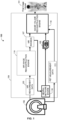
- FIG. 1 illustrates one embodiment of a nuclear imaging system 100.
- nuclear imaging system 100 includes image scanning system 102 and image reconstruction system 104.
- Image scanning system 102 in this example is a PET/MR scanner, but in other examples, can be a PET/CT scanner (e.g ., with CT as the corresponding co-modality instead of MR).
- Image scanning system 102 can capture MR images (e.g. , of a person), and generate MR measurement data 103 based on the MR scans.
- Image scanning system 102 can also capture PET images ( e.g., of the person), and generate PET measurement data 111 ( e.g. , sinogram data) based on the captured PET images.
- the PET measurement data 111 can represent anything imaged in the scanner's field-of-view (FOV) containing positron emitting isotopes.
- FOV field-of-view
- the PET measurement data 111 can represent whole-body image scans, such as image scans from a patient's head to thigh.
- Image scanning system 102 can transmit the MR measurement data 103 and the PET measurement data 111 to image reconstruction system 104.
- image reconstruction system 104 are implemented in hardware, such as in one or more field-programmable gate arrays (FPGAs), one or more application-specific integrated circuits (ASICs), one or more state machines, one or more computing devices, digital circuitry, or any other suitable circuitry.
- FPGAs field-programmable gate arrays
- ASICs application-specific integrated circuits
- state machines one or more computing devices, digital circuitry, or any other suitable circuitry.
- parts or all of image reconstruction system 104 can be implemented in software as executable instructions such that, when executed by one or more processors, cause the one or more processors to perform respective functions as described herein.
- the instructions can be stored in a non-transitory, computer-readable storage medium, for example.
- FIG. 2 illustrates a computing device 200 that can be employed by the image reconstruction system 104.
- Computing device 200 can implement, for example, one or more of the functions of image reconstruction system 104 described herein.
- Computing device 200 can include one or more processors 201, working memory 202, one or more input/output devices 203, instruction memory 207, a transceiver 204, one or more communication ports 207, and a display 206, all operatively coupled to one or more data buses 208.
- Data buses 208 allow for communication among the various devices.
- Data buses 208 can include wired, or wireless, communication channels.
- Processors 201 can include one or more distinct processors, each having one or more cores. Each of the distinct processors can have the same or different structure. Processors 201 can include one or more central processing units (CPUs), one or more graphics processing units (GPUs), application specific integrated circuits (ASICs), digital signal processors (DSPs), and the like.
- CPUs central processing units
- GPUs graphics processing units
- ASICs application specific integrated circuits
- DSPs digital signal processors
- Processors 201 can be configured to perform a certain function or operation by executing code, stored on instruction memory 207, embodying the function or operation.
- processors 201 can be configured to perform one or more of any function, method, or operation disclosed herein.
- Instruction memory 207 can store instructions that can be accessed (e.g ., read) and executed by processors 201.
- instruction memory 207 can be a non-transitory, computer-readable storage medium such as a read-only memory (ROM), an electrically erasable programmable read-only memory (EEPROM), flash memory, a removable disk, CD-ROM, any non-volatile memory, or any other suitable memory.
- ROM read-only memory
- EEPROM electrically erasable programmable read-only memory
- flash memory a removable disk
- CD-ROM any non-volatile memory, or any other suitable memory.
- instruction memory 207 can store instructions that, when executed by one or more processors 201, cause one or more processors 201 to perform one or more of the functions of image reconstruction system 104, such as one or more of the encoding segment 120 functions, one or more of the Radon inversion layer 140 functions, or one or more of the refinement and scaling segment 160 functions.
- Processors 201 can store data to, and read data from, working memory 202.
- processors 201 can store a working set of instructions to working memory 202, such as instructions loaded from instruction memory 207.
- Processors 201 can also use working memory 202 to store dynamic data created during the operation of computing device 200.
- Working memory 202 can be a random access memory (RAM) such as a static random access memory (SRAM) or dynamic random access memory (DRAM), or any other suitable memory.
- RAM random access memory
- SRAM static random access memory
- DRAM dynamic random access memory
- Input-output devices 203 can include any suitable device that allows for data input or output.
- input-output devices 203 can include one or more of a keyboard, a touchpad, a mouse, a stylus, a touchscreen, a physical button, a speaker, a microphone, or any other suitable input or output device.
- Communication port(s) 207 can include, for example, a serial port such as a universal asynchronous receiver/transmitter (UART) connection, a Universal Serial Bus (USB) connection, or any other suitable communication port or connection.
- communication port(s) 207 allows for the programming of executable instructions in instruction memory 207.
- communication port(s) 207 allow for the transfer (e.g., uploading or downloading) of data, such as MRI measurement data 103 and attenuation maps 105.
- Display 206 can display user interface 205.
- User interfaces 205 can enable user interaction with computing device 200.
- user interface 205 can be a user interface for an application that allows for the viewing of final image volumes 191.
- a user can interact with user interface 205 by engaging input-output devices 203.
- display 206 can be a touchscreen, where user interface 205 is displayed on the touchscreen.
- Transceiver 204 allows for communication with a network, such as a Wi-Fi network, an Ethernet network, a cellular network, or any other suitable communication network.
- a network such as a Wi-Fi network, an Ethernet network, a cellular network, or any other suitable communication network.
- transceiver 404 is configured to allow communications with the cellular network.
- Processor(s) 401 is operable to receive data from, or send data to, a network via transceiver 204.
- image reconstruction system 104 includes neural network engine 116, MR image reconstruction engine 119, and image volume reconstruction engine 118.
- MR image reconstruction engine 119 operates on MR measurement data 103 ( e.g. , MR raw data) to generate reconstructed MR image 107.
- MR image reconstruction engine 119 can generate reconstructed MR images 107 based on corresponding MR measurement data 103 using any suitable method known in the art.
- neural network engine 116 receives reconstructed MR images 107, and applies a trained neural network, such as a trained deep learning neural network as described herein, to the reconstructed MR images 107 to generate attenuation maps 105.
- the neural network could have been trained based on reconstructed MR images and measured attenuation maps (e.g ., ground truth data) during a training period, and further validated during a validation period ( e.g ., based on test data comprising MR images).
- the generated attenuation map 105 can identify density differences of a patient's body that can be used to correct for the absorption of photons emitted from radioactive decay (e.g ., radioactive decay of crystal material of image scanning system 102).
- Image volume reconstruction engine 118 obtains PET measurement data 111 (e.g., PET raw data) and the generated attenuation map 105, and reconstructs a final image volume 191.
- image volume reconstruction engine 118 applies the attenuation map 105 to PET measurement data 111 to generate the final image volume 191.
- Final image volume 191 can include image data that can be provided for display and analysis, for example.
- FIGS. 3A and 3B illustrate exemplary portions of image scanning system 102 including a gantry 302 and a patient table 310 located within the gantry 302.
- Gantry 302 may include crystal material 304, 306, such as LSO or LYSO crystals. Radioactive decay of crystal material 304 can cause gamma ray emissions, which can be detected by other crystal material 306. While FIG. 3B illustrates a patient 320 located on patient table 310, FIG. 3A includes no patient.
- image reconstruction system 104 can determine background levels of radiation generated by crystals 304 when no patient is located on patient table 310, as illustrated in FIG. 3A , based on gamma emissions captured by crystals 306. Further, to train a neural network, such as the neural network of neural network engine 116, image scanning system 102 captures MR scans and corresponding PET scans with patient 320 located on patient table 310, as illustrated in FIG. 3B . The patient 320 has no injected radioactivity, and thus detected activity ( e.g ., detected counts) is based on radioactive decay of crystals 304, 306. Image scanning system 102 can provide MR measurement data 103 and PET measurement data 111 to image reconstruction system 104 based on the MR scans and PET scans, respectively.
- a neural network such as the neural network of neural network engine 116
- Image reconstruction system 104 can reconstruct MR images based on the MR measurement data 103, and generate attenuation maps, such as attenuation maps 105, based on the reconstructed MR images and the detected background levels of radiation.
- Image reconstruction system 104 can train a neural network, such as the neural network of neural network engine 116, based on matching pairs of the attenuation maps and reconstructed MR images.
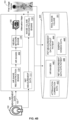
- FIG. 4A illustrates image reconstruction system 104 receiving MR measurement data 422 and PET measurement data 424 from image scanning system 102.
- Computing device 200 can reconstruct MR images 442 based on the received MR measurement data 422 according to any suitable method, and can store reconstructed MR images 442 in database 420.
- Database 420 can be a local or remote storage device, such as a cloud-based server, a disk ( e.g. , a hard disk), a memory device on another application server, a networked computer, or any other suitable data storage device.
- image reconstruction system 104 can receive PET measurement data 424 when no patient is within image scanning system 102 ( e.g. , blank scan as illustrated in FIG. 3A ), and can store PET measurement data without patient 444 in database 420.
- Computing device 220 can determine a background level of radiation based on PET measurement data without patient 444.
- image reconstruction system 104 can also receive PET measurement data 424 when a patient is within image scanning system 102 ( e.g. , as illustrated in FIG. 3B ), and store PET measurement data with patient 446 in database 420.
- Computing device 200 can generate attenuation maps, such as attenuation maps 105, based on PER measurement data with patient 446 and a background level of radiation as identified by PET measurement data without patient 444.
- computing device 200 can generate attenuation correction data 432 that identifies and characterizes the attenuation maps, and can store the attenuation correction data 432 within database 420.
- computing device 200 generates the attenuation maps based on PER measurement data with patient 446, the background level of radiation as identified by PET measurement data without patient 444, and reconstructed MR images 422.
- the MR images 422 can provide information about a patient's body as well as tissue boundaries within the patient, for example.
- computing device 200 scales the attenuation maps to a corresponding energy window identified by energy window data 448.
- the energy window may identify a range of electronvolts, such as 380 - 650 kev.
- attenuation maps may be scaled to an energy level, such as 511 kev.
- Computing device 200 can train the neural network based on the generated attenuation maps and corresponding MR images 422.
- FIG. 4B illustrates the generation of a final image volume 191 based on a trained neural network.
- the trained neural network can generate a predicted attenuation map based on an MR image.
- MR image reconstruction engine 119 receives MR measurement data 103, and generates an MR image 422 according to any suitable method.
- Neural network engine 116 receives the MR image 442 from MR image reconstruction engine 119, and applies a trained neural network to MR image 422 to generate an attenuation map 105.
- Image volume reconstruction engine 118 receives PET measurement data 111 from 102, where the PET measurement data 111 corresponds to the received MR measurement data 103 ( e.g.
- PET measurement data 111 and MR measurement data 103 are based on simultaneous PET and MR scans, respectively, of a same person).
- Image volume reconstruction engine 118 further receives the generated attenuation map 105, and adjusts ( e.g ., corrects) PET measurement data 111 based on attenuation map 105 to generate the final image volume 191.
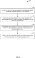
- FIG. 5 is a flowchart of an example method 500 to train a neural network.
- the method can be performed by one or more computing devices, such as computing device 200.
- first PET measurement data is received from an image scanning system.
- No volunteer e.g ., patient
- image reconstruction system 104 can receive the first PET measurement data, such as PET measurement data 111, from image scanning system 102.
- Image reconstruction system 104 can determine a background radiation level of the image scanning system based on the first PET measurement data.
- MR measurement data and corresponding second PET measurement data is received from the image scanning system.
- the MR measurement data and corresponding second PET measurement data are captured with a volunteer located within the image scanning system.
- image reconstruction system 104 can receive MR measurement data 103 and corresponding PET measurement data 111 from image scanning system 102 based on MR scans and PET scans performed for the volunteer.
- an attenuation correction is determined based on the first PET measurement data (e.g. , the background radiation level) and the second PET measurement data.
- An attenuation map can identify the attenuation correction.
- image reconstruction system 104 can generate an attenuation map 105 based on PET measurement data 111 and a previously determined background level of radiation of image scanning system 102, such as a background level identified by PET measurement data without patient 444 stored in database 420.
- a neural network is trained based on the attenuation correction and the received MR measurement data.
- image reconstruction system 104 can train a neural network of neural network engine 116 based on generated attenuation maps 105 and corresponding reconstructed MR images 107.
- the trained neural network is stored in a database, such as database 420.
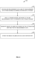
- FIG. 6 is a flowchart of an example method 600 to generate an image volume, and can be carried out by one or more computing device such as, for example, computing device 200.
- MR measurement data and PET measurement data (e.g ., sinogram data) is received from an image scanning system.
- the MR measurement data and PET measurement data correspond to MR and PET scans of a patient.
- image reconstruction system 104 can receive MR measurement data 103 and PET measurement data 111 from image scanning system 102 for a patient.
- a trained neural network is applied to the MR measurement data to generate an attenuation map.
- the neural network could have been trained in accordance with method 500.
- neural network engine 116 can apply a trained neural network to reconstructed MR images 442 to generate attenuation map 105.
- image volume data is generated based on the attenuation map and the received PET measurement data.
- the image volume data can identify and characterize an image volume (e.g ., a 3D image volume).
- image reconstruction system 104 can generate final image volume 191 based on attenuation maps 105 and corresponding PET measurement data 111.
- the final image volume is stored in a database.
- image reconstruction system 104 can store the generated final image volume 191 in database 420.
Landscapes
- Health & Medical Sciences (AREA)
- Life Sciences & Earth Sciences (AREA)
- Engineering & Computer Science (AREA)
- Medical Informatics (AREA)
- Physics & Mathematics (AREA)
- Radiology & Medical Imaging (AREA)
- Surgery (AREA)
- Nuclear Medicine, Radiotherapy & Molecular Imaging (AREA)
- Optics & Photonics (AREA)
- Pathology (AREA)
- Biophysics (AREA)
- Biomedical Technology (AREA)
- Heart & Thoracic Surgery (AREA)
- Molecular Biology (AREA)
- High Energy & Nuclear Physics (AREA)
- Animal Behavior & Ethology (AREA)
- General Health & Medical Sciences (AREA)
- Public Health (AREA)
- Veterinary Medicine (AREA)
- Nuclear Medicine (AREA)
- General Physics & Mathematics (AREA)
- Theoretical Computer Science (AREA)
Claims (14)
- Computerimplementiertes Verfahren (500), das Folgendes umfasst:Empfangen (502) erster Positronenemissionstomographie-Messdaten (PET-Messdaten) von einem Bildabtastsystem (102), wobei die ersten PET-Messdaten ohne Patienten (320) im Bildabtastsystem (102) erhalten wurden;Bestimmen eines Bezugsstrahlungspegels des Bildabtastsystems (102) auf der Grundlage der ersten PET-Messdaten;Empfangen (504) von Magnetresonanz-Messdaten (MR-Messdaten) und zweiten PET-Messdaten vom Bildabtastsystem (102), wobei die zweiten PET-Messdaten mit einem Patienten (320) im Bildabtastsystem (102) erhalten wurden;Erzeugen eines ersten Dämpfungskennfelds auf der Grundlage der ersten PET-Messdaten und der zweiten PET-Messdaten;Trainieren eines neuronalen Netzes mit dem ersten Dämpfungskennfeld (105) und den MR-Messdaten undSpeichern des trainierten neuronalen Netzes in einer Datenbank (420).
- Computerimplementiertes Verfahren nach Anspruch 1, das ferner Folgendes umfasst:Empfangen zweiter MR-Messdaten vom Bildabtastsystem (102) undAnwenden des trainierten neuronalen Netzes auf die zweiten MR-Messdaten, um ein zweites Dämpfungskennfeld zu bestimmen.
- Computerimplementiertes Verfahren nach Anspruch 2, das ferner ein Erzeugen eines Bilds auf der Grundlage des zweiten Dämpfungskennfelds umfasst.
- Computerimplementiertes Verfahren nach Anspruch 1, wobei das zweite Dämpfungskennfeld auf der Grundlage vorhergehender Bilder erzeugt wird, die unter Verwendung von MR-Messdaten berechnet wurden.
- Computerimplementiertes Verfahren nach Anspruch 1, wobei das erste Dämpfungskennfeld auf der Grundlage synthetischer Transmissionsbilder erzeugt wird.
- Computerimplementiertes Verfahren nach Anspruch 1, das ferner ein Erzeugen der synthetischen Transmissionsbilder auf der Grundlage einer detektierten Hintergrundstrahlung umfasst, die durch das Bildabtastsystem (102) erzeugt wurde.
- Computerimplementiertes Verfahren nach Anspruch 1, das ein Skalieren des ersten Dämpfungskennfelds auf der Grundlage eines entsprechenden Energiefensters umfasst.
- Computerimplementiertes Verfahren nach Anspruch 1, wobei das neuronale Netz ein neuronales Netz mit tiefgehendem Lernen ist.
- Nicht transitorisches computerlesbares Medium, das Befehle speichert, die dann, wenn sie durch mindestens einen Prozessor (201) ausgeführt werden, bewirken, dass der mindestens eine Prozessor (201) Operationen durchführt, die Folgendes umfassen:Empfangen erster Positronenemissionstomographie-Messdaten (PET-Messdaten) von einem Bildabtastsystem (102), wobei die ersten PET-Messdaten ohne Patienten (320) im Bildabtastsystem (102) erhalten wurden;Bestimmen eines Bezugsstrahlungspegels des Bildabtastsystems (102) auf der Grundlage der ersten PET-Messdaten;Empfangen von Magnetresonanz-Messdaten (MR-Messdaten) und zweiten PET-Messdaten vom Bildabtastsystem (102), wobei die zweiten PET-Messdaten mit einem Patienten (320) im Bildabtastsystem (102) erhalten wurden;Erzeugen eines ersten Dämpfungskennfelds auf der Grundlage der ersten PET-Messdaten und der zweiten PET-Messdaten;Trainieren eines neuronalen Netzes mit dem ersten Dämpfungskennfeld und den MR-Messdaten undSpeichern des trainierten neuronalen Netzes in einer Datenbank (420).
- Nicht transitorisches computerlesbares Medium nach Anspruch 9, das Befehle speichert, die dann, wenn sie durch mindestens einen Prozessor (201) ausgeführt werden, ferner bewirken, dass der mindestens eine Prozessor (201) Operationen ausführt, die die Verfahrensschritte nach Anspruch 2, den Ansprüchen 2 und 3, Anspruch 5 und Anspruch 6 oder Anspruch 7 umfassen.
- Nicht transitorisches computerlesbares Medium nach Anspruch 9, wobei das zweite Dämpfungskennfeld auf der Grundlage vorhergehender Bilder erzeugt wird, die unter Verwendung von MR-Messdaten berechnet wurden.
- System, das Folgendes umfasst:eine Datenbank (420); undmindestens einen Prozessor (201), der an die Datenbank (420) kommunikationstechnisch gekoppelt ist und konfiguriert ist zum:Empfangen erster Positronenemissionstomographie-Messdaten (PET-Messdaten) von einem Bildabtastsystem (102), wobei die ersten PET-Messdaten ohne Patienten (320) im Bildabtastsystem (102) erhalten wurden;Bestimmen eines Bezugsstrahlungspegels des Bildabtastsystems (102) auf der Grundlage der ersten PET-Messdaten;Empfangen von Magnetresonanz-Messdaten (MR-Messdaten) und zweiten PET-Messdaten vom Bildabtastsystem (102), wobei die zweiten PET-Messdaten mit einem Patienten (320) im Bildabtastsystem (102) erhalten wurden;Erzeugen eines ersten Dämpfungskennfelds auf der Grundlage der ersten PET-Messdaten und der zweiten PET-Messdaten;Trainieren eines neuronalen Netzes mit dem ersten Dämpfungskennfeld und den MR-Messdaten undSpeichern des trainierten neuronalen Netzes in der Datenbank (420).
- System nach Anspruch 12, wobei der mindestens eine Prozessor (201) konfiguriert ist, die Verfahrensschritte nach Anspruch 2, den Ansprüchen 2 und 3, den Ansprüchen 5 und 6 oder Anspruch 7 durchzuführen.
- System nach Anspruch 12, wobei das zweite Dämpfungskennfeld auf der Grundlage vorhergehender Bilder erzeugt wird, die unter Verwendung von MR-Messdaten berechnet wurden.
Applications Claiming Priority (2)
| Application Number | Priority Date | Filing Date | Title |
|---|---|---|---|
| US202062985120P | 2020-03-04 | 2020-03-04 | |
| PCT/EP2021/055044 WO2021175781A1 (en) | 2020-03-04 | 2021-03-01 | Methods and apparatus for deep learning based image attenuation correction |
Publications (3)
| Publication Number | Publication Date |
|---|---|
| EP4097683A1 EP4097683A1 (de) | 2022-12-07 |
| EP4097683C0 EP4097683C0 (de) | 2025-04-30 |
| EP4097683B1 true EP4097683B1 (de) | 2025-04-30 |
Family
ID=74873695
Family Applications (1)
| Application Number | Title | Priority Date | Filing Date |
|---|---|---|---|
| EP21711762.1A Active EP4097683B1 (de) | 2020-03-04 | 2021-03-01 | Verfahren und vorrichtung zur bilddämpfungskorrektur basierend auf tiefenlernen |
Country Status (4)
| Country | Link |
|---|---|
| US (1) | US20230056685A1 (de) |
| EP (1) | EP4097683B1 (de) |
| CN (1) | CN115176280A (de) |
| WO (1) | WO2021175781A1 (de) |
Families Citing this family (4)
| Publication number | Priority date | Publication date | Assignee | Title |
|---|---|---|---|---|
| EP4193194A1 (de) * | 2020-09-09 | 2023-06-14 | Siemens Medical Solutions USA, Inc. | Verbesserte dämpfungskarte erzeugt durch lso hintergrund |
| DE102022204448A1 (de) * | 2022-05-05 | 2023-11-09 | Siemens Healthcare Gmbh | Verfahren und System zum Erstellen eines quantitativen Positronen-Emissions-Tomographie-Bildes |
| CN115731315B (zh) * | 2022-06-27 | 2025-07-04 | 四川轻化工大学 | 基于深度学习的层析γ扫描图像重建方法 |
| CN121285338A (zh) * | 2023-06-09 | 2026-01-06 | 美国西门子医疗系统股份有限公司 | 用于医学成像的衰减校正 |
Family Cites Families (10)
| Publication number | Priority date | Publication date | Assignee | Title |
|---|---|---|---|---|
| US7324624B2 (en) * | 2005-10-14 | 2008-01-29 | Siemens Medical Solutions Usa, Inc. | Shifted transmission mock for nuclear medical imaging |
| JP5126049B2 (ja) * | 2007-12-28 | 2013-01-23 | 株式会社島津製作所 | 核医学診断装置、形態断層撮影診断装置、核医学用データ演算処理方法および形態断層画像演算処理方法 |
| US9507033B2 (en) * | 2013-02-05 | 2016-11-29 | Siemens Medical Solutions Usa, Inc. | Method and apparatus for compensating for scattering of emission gamma photons for PET imaging |
| WO2015034957A1 (en) * | 2013-09-03 | 2015-03-12 | Prescient Imaging LLC | Low noise transmission scan simultaneous with positron emission tomography |
| DE102015203932B4 (de) * | 2015-03-05 | 2016-09-29 | Siemens Healthcare Gmbh | Schwächungskorrektur von Emissionstomographie-Messdaten in Anwesenheit eines magnetischen Störfeldes |
| US10210634B2 (en) * | 2016-07-20 | 2019-02-19 | Shanghai United Imaging Healthcare Co., Ltd. | System and method for segmenting medical image |
| WO2019010648A1 (en) * | 2017-07-12 | 2019-01-17 | Shenzhen United Imaging Healthcare Co., Ltd. | SYSTEM AND METHOD FOR CORRECTION TO AIR |
| CN107411768B (zh) * | 2017-07-31 | 2020-11-10 | 东软医疗系统股份有限公司 | 一种设备校准方法和装置 |
| KR102210474B1 (ko) * | 2018-02-23 | 2021-02-01 | 서울대학교산학협력단 | 양전자방출 단층촬영 시스템 및 그것을 이용한 영상 재구성 방법 |
| WO2020082207A1 (en) * | 2018-10-22 | 2020-04-30 | Shanghai United Imaging Healthcare Co., Ltd. | Systems and methods for attenuation correction |
-
2021
- 2021-03-01 CN CN202180018471.3A patent/CN115176280A/zh active Pending
- 2021-03-01 EP EP21711762.1A patent/EP4097683B1/de active Active
- 2021-03-01 US US17/759,401 patent/US20230056685A1/en active Pending
- 2021-03-01 WO PCT/EP2021/055044 patent/WO2021175781A1/en not_active Ceased
Also Published As
| Publication number | Publication date |
|---|---|
| EP4097683A1 (de) | 2022-12-07 |
| EP4097683C0 (de) | 2025-04-30 |
| CN115176280A (zh) | 2022-10-11 |
| US20230056685A1 (en) | 2023-02-23 |
| WO2021175781A1 (en) | 2021-09-10 |
Similar Documents
| Publication | Publication Date | Title |
|---|---|---|
| EP4097683B1 (de) | Verfahren und vorrichtung zur bilddämpfungskorrektur basierend auf tiefenlernen | |
| US8406495B2 (en) | MR segmentation using transmission data in hybrid nuclear/MR imaging | |
| CN107644421B (zh) | 医学图像分割方法及系统 | |
| US9619905B2 (en) | Apparatus and method for generation of attenuation map | |
| US9332907B2 (en) | Extracting application dependent extra modal information from an anatomical imaging modality for use in reconstruction of functional imaging data | |
| US20180374205A1 (en) | System and method for image calibration | |
| CN106456098B (zh) | 衰减图的生成方法及系统 | |
| US11854126B2 (en) | Methods and apparatus for deep learning based image attenuation correction | |
| US10925554B2 (en) | Outside-FOV activity estimation using surview and prior patient data in positron emission tomography | |
| CN106491151A (zh) | Pet图像获取方法及系统 | |
| US20240404128A1 (en) | Methods and apparatus for synthetic computed tomography image generation | |
| US10772582B2 (en) | Multi-modal emission tomography quality based on patient and application | |
| US20220130079A1 (en) | Systems and methods for simultaneous attenuation correction, scatter correction, and de-noising of low-dose pet images with a neural network | |
| CN114943784B (zh) | 一种扫描设备的校正方法和系统 | |
| CN112529977B (zh) | 一种pet图像重建的方法和系统 | |
| KR102283934B1 (ko) | Pet 영상에 기반한 가상 ct 영상 및 감쇠보정 pet 영상 생성 방법 및 시스템 | |
| US20180005412A1 (en) | Reconstruction quality assessment with local non-uniformity in nuclear imaging | |
| US10684339B2 (en) | Dual flip angle multi-echo ultra-short echo time (DUFA-MUTE) magnetic resonance imaging (MRI) systems and methods | |
| JP4997575B2 (ja) | 減弱係数マップ作成装置、減弱係数マップ作成方法およびプログラム | |
| US11663758B2 (en) | Systems and methods for motion estimation in PET imaging using AI image reconstructions | |
| US20230036485A1 (en) | Data Driven Reconstruction in Emission Tomography | |
| US20250148663A1 (en) | Methods and apparatus for pet image reconstruction using multi-view histo-images of attenuation correction factors | |
| US20250245864A1 (en) | Methods and apparatus for medical image reconstruction using machine learning based processes | |
| Choi et al. | Can patient-specific acquisition protocol improve performance on defect detection task in myocardial perfusion SPECT? | |
| CN110992280B (zh) | Pet图像衰减校正方法、装置、计算机设备 |
Legal Events
| Date | Code | Title | Description |
|---|---|---|---|
| STAA | Information on the status of an ep patent application or granted ep patent |
Free format text: STATUS: UNKNOWN |
|
| STAA | Information on the status of an ep patent application or granted ep patent |
Free format text: STATUS: THE INTERNATIONAL PUBLICATION HAS BEEN MADE |
|
| PUAI | Public reference made under article 153(3) epc to a published international application that has entered the european phase |
Free format text: ORIGINAL CODE: 0009012 |
|
| STAA | Information on the status of an ep patent application or granted ep patent |
Free format text: STATUS: REQUEST FOR EXAMINATION WAS MADE |
|
| 17P | Request for examination filed |
Effective date: 20220831 |
|
| AK | Designated contracting states |
Kind code of ref document: A1 Designated state(s): AL AT BE BG CH CY CZ DE DK EE ES FI FR GB GR HR HU IE IS IT LI LT LU LV MC MK MT NL NO PL PT RO RS SE SI SK SM TR |
|
| DAV | Request for validation of the european patent (deleted) | ||
| DAX | Request for extension of the european patent (deleted) | ||
| GRAP | Despatch of communication of intention to grant a patent |
Free format text: ORIGINAL CODE: EPIDOSNIGR1 |
|
| STAA | Information on the status of an ep patent application or granted ep patent |
Free format text: STATUS: GRANT OF PATENT IS INTENDED |
|
| INTG | Intention to grant announced |
Effective date: 20241120 |
|
| GRAS | Grant fee paid |
Free format text: ORIGINAL CODE: EPIDOSNIGR3 |
|
| GRAA | (expected) grant |
Free format text: ORIGINAL CODE: 0009210 |
|
| STAA | Information on the status of an ep patent application or granted ep patent |
Free format text: STATUS: THE PATENT HAS BEEN GRANTED |
|
| AK | Designated contracting states |
Kind code of ref document: B1 Designated state(s): AL AT BE BG CH CY CZ DE DK EE ES FI FR GB GR HR HU IE IS IT LI LT LU LV MC MK MT NL NO PL PT RO RS SE SI SK SM TR |
|
| REG | Reference to a national code |
Ref country code: CH Ref legal event code: EP Ref country code: GB Ref legal event code: FG4D |
|
| REG | Reference to a national code |
Ref country code: DE Ref legal event code: R096 Ref document number: 602021029979 Country of ref document: DE |
|
| REG | Reference to a national code |
Ref country code: IE Ref legal event code: FG4D |
|
| U01 | Request for unitary effect filed |
Effective date: 20250430 |
|
| U07 | Unitary effect registered |
Designated state(s): AT BE BG DE DK EE FI FR IT LT LU LV MT NL PT RO SE SI Effective date: 20250512 |
|
| PG25 | Lapsed in a contracting state [announced via postgrant information from national office to epo] |
Ref country code: ES Free format text: LAPSE BECAUSE OF FAILURE TO SUBMIT A TRANSLATION OF THE DESCRIPTION OR TO PAY THE FEE WITHIN THE PRESCRIBED TIME-LIMIT Effective date: 20250430 |
|
| PG25 | Lapsed in a contracting state [announced via postgrant information from national office to epo] |
Ref country code: GR Free format text: LAPSE BECAUSE OF FAILURE TO SUBMIT A TRANSLATION OF THE DESCRIPTION OR TO PAY THE FEE WITHIN THE PRESCRIBED TIME-LIMIT Effective date: 20250731 Ref country code: NO Free format text: LAPSE BECAUSE OF FAILURE TO SUBMIT A TRANSLATION OF THE DESCRIPTION OR TO PAY THE FEE WITHIN THE PRESCRIBED TIME-LIMIT Effective date: 20250730 |
|
| PG25 | Lapsed in a contracting state [announced via postgrant information from national office to epo] |
Ref country code: PL Free format text: LAPSE BECAUSE OF FAILURE TO SUBMIT A TRANSLATION OF THE DESCRIPTION OR TO PAY THE FEE WITHIN THE PRESCRIBED TIME-LIMIT Effective date: 20250430 |
|
| PG25 | Lapsed in a contracting state [announced via postgrant information from national office to epo] |
Ref country code: HR Free format text: LAPSE BECAUSE OF FAILURE TO SUBMIT A TRANSLATION OF THE DESCRIPTION OR TO PAY THE FEE WITHIN THE PRESCRIBED TIME-LIMIT Effective date: 20250430 |
|
| PG25 | Lapsed in a contracting state [announced via postgrant information from national office to epo] |
Ref country code: RS Free format text: LAPSE BECAUSE OF FAILURE TO SUBMIT A TRANSLATION OF THE DESCRIPTION OR TO PAY THE FEE WITHIN THE PRESCRIBED TIME-LIMIT Effective date: 20250731 |
|
| PG25 | Lapsed in a contracting state [announced via postgrant information from national office to epo] |
Ref country code: IS Free format text: LAPSE BECAUSE OF FAILURE TO SUBMIT A TRANSLATION OF THE DESCRIPTION OR TO PAY THE FEE WITHIN THE PRESCRIBED TIME-LIMIT Effective date: 20250830 |
|
| PG25 | Lapsed in a contracting state [announced via postgrant information from national office to epo] |
Ref country code: SM Free format text: LAPSE BECAUSE OF FAILURE TO SUBMIT A TRANSLATION OF THE DESCRIPTION OR TO PAY THE FEE WITHIN THE PRESCRIBED TIME-LIMIT Effective date: 20250430 |
|
| PG25 | Lapsed in a contracting state [announced via postgrant information from national office to epo] |
Ref country code: CZ Free format text: LAPSE BECAUSE OF FAILURE TO SUBMIT A TRANSLATION OF THE DESCRIPTION OR TO PAY THE FEE WITHIN THE PRESCRIBED TIME-LIMIT Effective date: 20250430 |
|
| PG25 | Lapsed in a contracting state [announced via postgrant information from national office to epo] |
Ref country code: SK Free format text: LAPSE BECAUSE OF FAILURE TO SUBMIT A TRANSLATION OF THE DESCRIPTION OR TO PAY THE FEE WITHIN THE PRESCRIBED TIME-LIMIT Effective date: 20250430 |