EP4097375B1 - Dual-clutch transmission - Google Patents
Dual-clutch transmission Download PDFInfo
- Publication number
- EP4097375B1 EP4097375B1 EP21702991.7A EP21702991A EP4097375B1 EP 4097375 B1 EP4097375 B1 EP 4097375B1 EP 21702991 A EP21702991 A EP 21702991A EP 4097375 B1 EP4097375 B1 EP 4097375B1
- Authority
- EP
- European Patent Office
- Prior art keywords
- clutch
- gear
- shaft
- transmission
- central
- Prior art date
- Legal status (The legal status is an assumption and is not a legal conclusion. Google has not performed a legal analysis and makes no representation as to the accuracy of the status listed.)
- Active
Links
Images






Classifications
-
- F—MECHANICAL ENGINEERING; LIGHTING; HEATING; WEAPONS; BLASTING
- F16—ENGINEERING ELEMENTS AND UNITS; GENERAL MEASURES FOR PRODUCING AND MAINTAINING EFFECTIVE FUNCTIONING OF MACHINES OR INSTALLATIONS; THERMAL INSULATION IN GENERAL
- F16H—GEARING
- F16H3/00—Toothed gearings for conveying rotary motion with variable gear ratio or for reversing rotary motion
- F16H3/006—Toothed gearings for conveying rotary motion with variable gear ratio or for reversing rotary motion power being selectively transmitted by parallel flow paths, e.g. dual clutch transmissions
-
- F—MECHANICAL ENGINEERING; LIGHTING; HEATING; WEAPONS; BLASTING
- F16—ENGINEERING ELEMENTS AND UNITS; GENERAL MEASURES FOR PRODUCING AND MAINTAINING EFFECTIVE FUNCTIONING OF MACHINES OR INSTALLATIONS; THERMAL INSULATION IN GENERAL
- F16D—COUPLINGS FOR TRANSMITTING ROTATION; CLUTCHES; BRAKES
- F16D25/00—Fluid-actuated clutches
- F16D25/10—Clutch systems with a plurality of fluid-actuated clutches
-
- F—MECHANICAL ENGINEERING; LIGHTING; HEATING; WEAPONS; BLASTING
- F16—ENGINEERING ELEMENTS AND UNITS; GENERAL MEASURES FOR PRODUCING AND MAINTAINING EFFECTIVE FUNCTIONING OF MACHINES OR INSTALLATIONS; THERMAL INSULATION IN GENERAL
- F16H—GEARING
- F16H57/00—General details of gearing
- F16H57/04—Features relating to lubrication or cooling or heating
- F16H57/0434—Features relating to lubrication or cooling or heating relating to lubrication supply, e.g. pumps; Pressure control
- F16H57/0436—Pumps
-
- B—PERFORMING OPERATIONS; TRANSPORTING
- B60—VEHICLES IN GENERAL
- B60K—ARRANGEMENT OR MOUNTING OF PROPULSION UNITS OR OF TRANSMISSIONS IN VEHICLES; ARRANGEMENT OR MOUNTING OF PLURAL DIVERSE PRIME-MOVERS IN VEHICLES; AUXILIARY DRIVES FOR VEHICLES; INSTRUMENTATION OR DASHBOARDS FOR VEHICLES; ARRANGEMENTS IN CONNECTION WITH COOLING, AIR INTAKE, GAS EXHAUST OR FUEL SUPPLY OF PROPULSION UNITS IN VEHICLES
- B60K17/00—Arrangement or mounting of transmissions in vehicles
- B60K17/34—Arrangement or mounting of transmissions in vehicles for driving both front and rear wheels, e.g. four wheel drive vehicles
- B60K17/344—Arrangement or mounting of transmissions in vehicles for driving both front and rear wheels, e.g. four wheel drive vehicles having a transfer gear
-
- B—PERFORMING OPERATIONS; TRANSPORTING
- B60—VEHICLES IN GENERAL
- B60Y—INDEXING SCHEME RELATING TO ASPECTS CROSS-CUTTING VEHICLE TECHNOLOGY
- B60Y2200/00—Type of vehicle
- B60Y2200/10—Road Vehicles
- B60Y2200/13—Bicycles; Tricycles
-
- F—MECHANICAL ENGINEERING; LIGHTING; HEATING; WEAPONS; BLASTING
- F16—ENGINEERING ELEMENTS AND UNITS; GENERAL MEASURES FOR PRODUCING AND MAINTAINING EFFECTIVE FUNCTIONING OF MACHINES OR INSTALLATIONS; THERMAL INSULATION IN GENERAL
- F16D—COUPLINGS FOR TRANSMITTING ROTATION; CLUTCHES; BRAKES
- F16D21/00—Systems comprising a plurality of actuated clutches
- F16D21/02—Systems comprising a plurality of actuated clutches for interconnecting three or more shafts or other transmission members in different ways
-
- F—MECHANICAL ENGINEERING; LIGHTING; HEATING; WEAPONS; BLASTING
- F16—ENGINEERING ELEMENTS AND UNITS; GENERAL MEASURES FOR PRODUCING AND MAINTAINING EFFECTIVE FUNCTIONING OF MACHINES OR INSTALLATIONS; THERMAL INSULATION IN GENERAL
- F16H—GEARING
- F16H2200/00—Transmissions for multiple ratios
- F16H2200/003—Transmissions for multiple ratios characterised by the number of forward speeds
- F16H2200/0078—Transmissions for multiple ratios characterised by the number of forward speeds the gear ratio comprising twelve or more forward speeds
-
- F—MECHANICAL ENGINEERING; LIGHTING; HEATING; WEAPONS; BLASTING
- F16—ENGINEERING ELEMENTS AND UNITS; GENERAL MEASURES FOR PRODUCING AND MAINTAINING EFFECTIVE FUNCTIONING OF MACHINES OR INSTALLATIONS; THERMAL INSULATION IN GENERAL
- F16H—GEARING
- F16H2200/00—Transmissions for multiple ratios
- F16H2200/0082—Transmissions for multiple ratios characterised by the number of reverse speeds
- F16H2200/0086—Transmissions for multiple ratios characterised by the number of reverse speeds the gear ratios comprising two reverse speeds
Definitions
- the present technology relates to dual-clutch transmissions.
- Off-road vehicles have powertrains that can incorporate different types of transmission, such as a continuously variable transmission (CVT) or a manually operated transmission.
- CVT continuously variable transmission
- other types of transmissions could be used in off-road vehicles and offer different performance in certain conditions than the aforementioned CVT and manually operated transmission.
- a dual-clutch transmission is a type of transmission that includes first and second clutches.
- the first clutch drives the odd-numbered transmission gears via a first shaft
- the second clutch drives the even-numbered transmission gears via a second shaft.
- gear changes can be accomplished without interrupting torque distribution to the driven wheels.
- the torque of the engine is applied to one clutch at the same time as it is being disconnected from the other clutch. Since alternate gear ratios can preselect an odd transmission gear on one shaft while the vehicle is being driven in an even transmission gear (and vice versa), DCTs offer good shifting performance and efficiency in certain conditions.
- dual-clutch transmissions have not been made widely available in off-road vehicles yet. Reasons causing the delay of their widespread adoption in off-road vehicles include relatively high manufacturing costs and packaging issues due to the limited space in the engine compartment.
- US2017/167550 discloses an internal combustion engine comprising: a hydraulic clutch operatively connected to an oil pump for supplying oil under pressure for changing over transmission of a driving force of a crankshaft to a speed change shaft between engagement and disengagement; and a hydraulic pressure adjustment apparatus configured to adjust the hydraulic pressure of the oil fed under pressure from the oil pump and to be supplied to the clutch in response to a timing of engagement or disengagement of the hydraulic clutch.
- the oil is supplied from the oil pump to the hydraulic clutch through the hydraulic pressure adjustment apparatus.
- US3254541A discloses a vehicle transmission gearing comprising a drive input shaft having operable connection to a source of power, a reversible output shaft, forward and reverse drive cross shafts each rotatably mounting high and low speed gears in axially spaced relation, constantly meshed gearing interconnecting the input shaft and the forward drive cross shaft, a high speed gear fixed on the output shaft meshed with the high speed gears on both of said cross shafts, a low speed gear fixed on the output shaft meshed with both of the low speed gears on the cross shafts, and means for selectively clutching any one of the high and low speed gears on the cross shafts to its associated cross shaft comprising an axially shiftable clutch collar surrounding each of the cross shafts, constantly meshed gears on the collars and clutch units disposed between each of the collars and the high and low speed gears on the associated cross shaft
- a dual-clutch transmission 100 will be described herein with respect to a four-wheel side-by-side off-road vehicle 20, but it is contemplated that the DCT 100 could be used in other types of vehicles such as, but not limited to, off-road vehicles having more or less than four wheels and/or more or less than two seats.
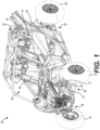
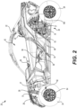
- the general features of the off-road vehicle 20 will be described with respect to Figures 1 and 2 .
- the vehicle 20 has a frame 22, two front wheels 24 connected to a front of the frame 22 by front suspension assemblies 26 and two rear wheels 28 connected to the frame 22 by rear suspension assemblies 30 such as those described in United States Patent Serial No. 9,981,519 B2, dated May 29, 2018 .
- Each front suspension assembly 26 has a front shock absorber assembly 27 including a shock absorber 29 and a spring 31.
- Each rear suspension assembly 30 has a rear shock absorber assembly 33 including a shock absorber 35 and a spring 37.
- Ground engaging members other than wheels 24, 28 are contemplated for the vehicle 20, such as tracks or skis.
- the vehicle 20 could include more or less than four ground engaging members.
- different combinations of ground engaging members, such as tracks used in combination with skis are contemplated.
- the frame 22 defines a central cockpit area 42 inside which are disposed a driver seat 44 and a passenger seat 46.
- the driver seat 44 is disposed on the left side of the vehicle 20 and the passenger seat 46 is disposed on the right side of the vehicle 20.
- the driver seat 44 could be disposed on the right side of the vehicle 20 and that the passenger seat 46 could be disposed on the left side of the vehicle 20.
- the vehicle 20 further has a seat belt 47 for each one of the seats 44, 46.
- a steering wheel 48 is disposed in front of the driver seat 44. The steering wheel 48 is used to turn the front wheels 24 to steer the vehicle 20.
- Various displays and gauges 50 are disposed in front of the steering wheel 48 to provide information to the driver regarding the operating conditions of the vehicle 20.
- Examples of displays and gauges 50 include, but are not limited to, a speedometer, a tachometer, a fuel gauge, a transmission position display, and an oil temperature gauge.
- an internal combustion engine 52 (schematically shown in Figures 2 and 3 ) is connected to the frame 22 in a rear portion of the vehicle 20.
- the engine 52 has a crankshaft 53 (schematically shown in Figure 3 ) that is connected to the DCT 100 disposed behind the engine 52 (both schematically shown in Figure 2 ).
- the DCT 100 includes a subtransmission 700 ( Figures 4 , 5 and 14 ) operatively connected to a driveline 54 (schematically shown in Figure 2 ) of the vehicle 20 for operatively connecting the front and rear wheels 24, 28 to the engine 52 in order to propel the vehicle 20.
- a gear shifter 56 located between the seats 44, 46 operates the DCT 100 and the subtransmission 700 of the vehicle 20, and enables the driver to select one of a plurality of gear configurations for operation of the vehicle 20. It is contemplated that paddle shifters (not shown) could be mounted to the steering wheel 48 for enabling the driver to select a gear for operation of the vehicle 20.
- the gear configurations made available by the DCT 100 include a reverse gear, and forward first, second, third, fourth, fifth, sixth and seventh gear.
- the gear configurations made available by the subtransmission 700 include park, neutral, high forward gears, and low forward gears.
- the DCT 100 and the subtransmission 700 enable fourteen different forward-going gear configurations and two different reverse gear configurations. It is contemplated that the sequence and/or number of gear configurations could be different than as shown herein in other implementations.
- a driving mode selector button 58 ( Figure 2 ) also enables the driver to select 2x4 or 4x4 operation of the vehicle 20.
- the driveline 54 includes a front propeller shaft 60 which extends horizontally to the left of the engine 52 towards a front differential assembly 62 (schematically shown in Figure 2 ).
- the front differential assembly 62 is operatively connected to the front wheels 24 via front wheel axle assemblies (not shown).
- the front differential assembly 62 includes an electronic selector 64 (also schematically shown in Figure 2 ) operatively connected to the driving mode selector button 58.
- the electronic selector 64 allows to selectively connect the front propeller shaft 60 to the front wheel axle assemblies to enable 4x4 driving mode of the vehicle 20, or to selectively disconnect the front propeller shaft 60 from the front wheel axle assemblies to enable 2x4 driving mode of the vehicle 20 ( i.e. with only the rear wheels 28 propelling the vehicle 20).
- the vehicle 20 further includes other components such as brakes, a radiator, headlights, and the like. As it is believed that these components would be readily recognized by one of ordinary skill in the art, further explanation and description of these components will not be provided herein.
- the DCT 100 includes a housing 102 that is separate from the internal combustion engine 52.
- the housing 102 is flanged to a rear face of the internal combustion engine 52.
- the housing 102 has a dedicated hydraulic and lubrication oil circuit, separated from that of the engine 52.
- a transmission fluid pump 104 (schematically shown in Figure 3 ) is received inside the housing 102.
- the transmission fluid pump 104 is adapted to selectively pump oil-based fluids. Again, in the present implementation, the transmission fluid pump 104 is separated from any other pump(s) the engine 52 may have.
- the DCT 100 includes an input damper 120 adapted to reduce the torque variations from the crankshaft 53 to the DCT 100.
- the input damper 120 has a hollow shaft 122 defining splines 124 for connection to the crankshaft 53 (as can be understood from Figure 3 ).
- the hollow shaft 122 has a front end 126 and a rear end 128 defined consistently with the forward travel direction of the vehicle 20 ( Figures 6 and 8 ).
- the hollow shaft 122 also defines an input damper axis 130 about which the hollow shaft 122 rotates.
- An input member 140 is slidably engaged to the hollow shaft 122 and positioned between the front and rear ends 126, 128.
- the input member 140 has splines 141 complementary to splines 124, and the input member 140 can slide axially along the input damper axis 130 between the front and rear ends 126, 128.
- the input member 140 defines three recesses 142 angularly displaced by about 120 degrees relative to the input damper axis 130.
- a disc spring assembly 150 is connected to the hollow shaft 122 and extends between the front and rear ends 126, 128. The disc spring assembly 150 abuts a shoulder 152 of the hollow shaft 122 and biases the input member 140 axially along the input damper axis 130 towards the rear end 128 of the hollow shaft 122.
- An output member 160 is disposed over the hollow shaft 122 and positioned between the input member 140 and the rear end 128 of the hollow shaft 122.
- the output member 160 is supported by bearings 162 disposed between the output member 160 and a connector 164 disposed adjacent the rear end 128 of the hollow shaft 122.
- the connector 164 retains the output member 160 on the hollow shaft 122.
- the output member 160 defines three cams 166 also angularly displaced by about 120 degrees relative to the input damper axis 130 ( Figure 6 ).
- the three cams 166 are structured and configured for engaging the corresponding three recesses 142 of the input member 140 when the input member 140 is biased towards the rear end 128 of the hollow shaft 122.
- An output gear 170 is connected to the output member 160, and also rotates about the input damper axis 130.
- the output gear 170 has a plurality of teeth 172.
- a pump gear 180 is connected to the output gear 170 via three fasteners 182, and extends between the output gear 170 and the disc spring assembly 150. The pump gear 180 also rotates about the input damper axis 130.
- the pump gear 180 is adapted to drive the transmission fluid pump 104 ( Figure 2 ).
- An auxiliary output gear 190 is connected to the output gear 170 via a ring 191 having coil spring assemblies 192.
- the auxiliary output gear 190 is biased by the coil spring assemblies 192 and has a plurality of teeth 194.
- the number of teeth 172 of the output gear 170 matches the number of teeth 194 of the auxiliary output gear 190.
- the coil spring assemblies 192 permits angular displacements of the auxiliary output gear 190 about the input damper axis 130 relative to the output gear 170.
- the auxiliary output gear 190 provides preload on the teeth 172 of the output gear 170 and reduces backlash that can occur between the output gear 170 and a central clutch gear 200 described below.
- the DCT 100 includes a dual-clutch 202 having first and second clutches 204a, 204b.
- the dual clutch 202 includes a clutch pack drum 220 that is adapted to rotate inside the housing 102, and the central clutch gear 200 is connected to the clutch pack drum 220 via fasteners 221 ( Figures 7 and 9 ).
- the central clutch gear 200 has teeth 212 adapted to mesh with the teeth 172, 194 of the output gear 170 and the auxiliary output gear 190.
- the central clutch gear 200 is thus operatively connected to the crankshaft 53 of the internal combustion engine 52 via the input damper 120.
- having the input damper 120 located outside the clutch pack drum 220 offers more flexibility to package the DCT 100 in the rear portion of the frame 22 of the vehicle 20 supporting the engine 52 and the DCT 100.
- having the input damper 120 located outside the clutch pack drum 220 improves the overall packaging of the DCT 100 in the rear portion of the vehicle 20.
- having the input damper 120 located outside the clutch pack drum 220 allows for a greater angle of relative rotation between the input member 140 and the output member 160 compared to an input damper that would be integrated in the clutch pack drum 220. The greater angle of relative rotation between the input member 140 and the output member 160 improves the damping provided by the input damper 120.
- the central clutch gear 200 has a front face 212a and a rear face 212b.
- the central clutch gear 200 defines a clutch gear plane 214 and a clutch gear rotation axis 216 normal to the clutch gear plane 214 ( Figure 8 ). It is to be appreciated that the clutch gear rotation axis 216 is parallel to the input damper axis 130, and extends above and to the right of the input damper axis 130 ( Figure 4 ).
- the clutch pack drum 220 includes a front clutch pack basket 222a disposed in front of the central clutch gear 200, and a rear clutch pack basket 222b disposed behind the central clutch gear 200.
- the front and rear clutch pack baskets 222a, 222b are interconnected using the fasteners 221 extending through the central clutch gear 200.
- the front and rear clutch pack baskets 222a, 222b are identical.
- the front and rear clutch pack baskets 222a, 222b are symmetrical about the clutch gear plane 214.
- the front and rear clutch pack baskets 222a, 222b could be structured otherwise in other implementations.
- the front and rear clutch pack baskets 222a, 222b each have a cylindrical wall 226 defining splines 228 and a plurality of holes 230.
- a front clutch pack 240a is received in the clutch pack basket 222a and is disposed in front of the central clutch gear 200.
- the clutch pack 240a includes a plurality of clutch plates 242 having teeth 244 extending away from the clutch gear rotation axis 216 and engaging the splines 228 of the clutch pack basket 222a for rotating with the clutch pack drum 220 ( Figure 13A ).
- the clutch plates 242 are movable axially in a direction 246 (see double arrow 246 in Figures 13A to 13C ) defined by the clutch gear rotation axis 216.
- the clutch plates 242 have disc surfaces including relatively low friction material.
- the front clutch pack 240a further includes a plurality of clutch disks 250 disposed alternatingly with the clutch plates 242 in the direction 246 ( Figure 13A ).
- the clutch disks 250 have disc surfaces including a relatively high friction material.
- the clutch disks 250 have teeth 254 extending towards the clutch gear rotation axis 216.
- the clutch disks 250 are also movable axially in the direction 246 defined by the clutch gear rotation axis 216. As will become apparent from the description below, when the clutch disks 250 are selectively engaged by the clutch plates 242, the clutch disks 250 rotate with the clutch pack drum 220.
- a front clutch hub 260a is received in the clutch pack 240a and is disposed in front of the central clutch gear 200.
- the clutch hub 260a defines splines 262 structured to engage with the teeth 254 of the clutch disks 250 of the clutch pack 240a.
- the clutch disks 250 are movable axially relative to the clutch hub 260a in the direction 246 defined by the clutch gear rotation axis 216 as the teeth 254 slide axially in the splines 262.
- the clutch hub 260a rotates with the clutch pack drum 220.
- the clutch hub 260a has three arms 264 connecting a rim portion 266 of the clutch hub 260a (defining the splines 262) to a central portion 268 of the clutch hub 260a. Holes 270 are defined in each of the arms 264 for receiving fasteners 272 ( Figure 13A ). The central portion 268 defines splines 274. Referring to Figures 10 , 11 and 13A , a plurality of bores 280 are defined in the central portion 268, in the arms 264 and in the rim portion 266. The bores 280 are adapted for allowing flow of fluid therethrough, as will become apparent from the following description.
- a lubrication cover 300a is also received in the clutch pack 240a.
- the lubrication cover 300a is disposed in front of the central clutch gear 200 and behind the front clutch hub 260a.
- the lubrication cover 300a defines a plurality of apertures 302 on a rim portion 304 thereof.
- Three threaded holes 306 are defined in the lubrication cover 300a for receiving the fasteners 272. When the fasteners 272 extend through the holes 270 of the clutch hub 260a and are engaged in the threaded holes 306 of the lubrication cover 300a, the lubrication cover 300a and the clutch hub 260a are interconnected.
- Passages 310 are defined in the lubrication cover 300a and extend around each one of the threaded holes 306. The passages 310 are adapted for allowing flow of fluid therethrough, as will become apparent from the following description.
- the DCT 100 further includes a pressure plate 320a disposed in front of the central clutch gear 200.
- the pressure plate 320a is disposed between the central clutch gear 200 and the lubrication cover 300a.
- a ring 322a is connected to the central clutch gear 200, and coil spring assemblies 324a interconnect the pressure plate 320a to the central clutch gear 200.
- the pressure plate 320a rotates with the central clutch gear 200, and is movable axially in the direction 246 upon compression and extension of the coil spring assemblies 324a.
- the pressure plate 320a has a front face 332a ( Figure 10 ) including a rim portion 334a.
- the rim portion 334a of the pressure plate 320a is structured to selectively engage the clutch plate 242 that is closest to the central clutch gear 200.
- the pressure plate 320a further has a rear face 342a ( Figure 11 ) where six pads 344 project therefrom.
- the pads 344 are structured for abutting the front face 212a of the central clutch gear 200 and to leave a spacing between the front face 212a of the central clutch gear 200 and the rear face 342a of the pressure plate 320a (the spacing is shown in Figure 13A ).
- a chamber 350a is defined between the front face 212a of the central clutch gear 200 and the rear face 342a of the pressure plate 320a.
- the pressure plate 320a further defines a pressure plate passage 360a extending between the front face 332a and the rear face 342a. More particularly, the pressure plate passage 360a starts on the rear face 342a from one of the pads 344 ( Figure 11 ).
- the pressure plate passage 360a is adapted for allowing flow of fluid therethrough, as will become apparent from the following description.
- a shaft 400a is connected to the front clutch hub 260a via teeth (not shown) engaging the splines 274 of central portion 268.
- the shaft 400a is coaxial with the clutch gear rotation axis 216.
- the shaft 400a defines three passages 410, 412 ( Figure 13A ), and 414 ( Figure 8 ) adapted for flowing fluid therethrough.
- a manifold 420 ( Figure 8 ) is connected to the front portion of the shaft 400a.
- the manifold 420 fluidly connects the transmission fluid pump 104 to the passages 410, 412, 414.
- a plurality of transmission gears 600 are operatively connected to the shaft 400a.
- the transmission gears 600 include the gears corresponding to the first gear 601, third gear 603, fifth gear 605, and seventh gear 607 of the DCT 100.
- the transmission gears 600 are all disposed behind the central clutch gear 200.
- Arrows show the flow of fluid through the dual-clutch 202 in Figures 10 , 11 , 13A and 13B when the dual-clutch 202 rotates.
- fluid When fluid is selectively supplied in the passage 410 from the transmission fluid pump 104, fluid flows through the shaft 400a in the passage 410 ( Figure 13A ), through passages 430a defined in the central clutch gear 200 ( Figures 9 and 13A ) and into the chamber 350a. Since the pads 344 abut the front face 212a of the central clutch gear 200, fluid flows through the spacing between the pressure plate 320a and the central clutch gear 200, and fills the chamber 350a. The pads 344 are thus structured for selectively allowing flow of fluid from the passage 410 to the chamber 350a.
- the pressurized fluid in the chamber 350a overcomes the biasing force of the coil spring assemblies 324a and moves the pressure plate 320a axially away from the central clutch gear 200 (i.e. forward of the central clutch gear 200), as shown between Figures 13A and 13B .
- the pressure plate 320a selectively squeezes the clutch plates 242 and the clutch disks 250 together for engaging the clutch plates 242 with the clutch disks 250.
- the front clutch hub 260a and the lubrication cover 300a are thus rotatable with the clutch pack drum 220 and the central clutch gear 200, and the shaft 400a drives the transmission gears 600 corresponding to the first gear 601, third gear 603, fifth gear 605 and seventh gear 607 of the DCT 100.
- first clutch 204a is operatively connected to the transmission gear 600 corresponding to the first gear 601 of the DCT 100, which can have a heavy usage, for example, when the vehicle 20 launches repetitively, additional lubrication and cooling to the first clutch 204a provided by fluid flowing through the passage 414 and the bore 280 is advantageous under certain conditions.
- a rear clutch pack 240b is received in the clutch pack basket 222b and is disposed behind the central clutch gear 200.
- the rear clutch pack 240b also includes a plurality of clutch plates 242 having teeth 244 extending away from the clutch gear rotation axis 216 and engaging the splines 228 of the clutch pack basket 222b for rotating with the clutch pack drum 220 ( Figures 13A to 13C ).
- the front and rear clutch packs 240a, 240b are identical, but they could be structured otherwise in other implementations. This feature assists in reducing the manufacturing costs of the DCT 100.
- the clutch plates 242 have disc surfaces including a relatively low friction material.
- the rear clutch pack 240b further includes a plurality of clutch disks 250 disposed alternatingly with the clutch plates 242 in the direction 246 ( Figure 13A ).
- the clutch disks 250 have disc surfaces including a relatively high friction material.
- the clutch disks 250 have teeth 254 extending towards the clutch gear rotation axis 216 ( Figures 13A to 13C ).
- the clutch disks 250 are also movable axially in the direction 246 defined by the clutch gear rotation axis 216.
- a rear clutch hub 260b is received in the clutch pack 240b and is disposed behind the central clutch gear 200.
- the clutch hub 260b also defines splines 262 structured to engage with the teeth 254 of the clutch disks 250 of the clutch pack 240b.
- the clutch disks 250 are movable axially relative to the clutch hub 260b in the direction 246 ( Figures 13A to 13C ).
- the clutch hub 260b rotates with the clutch pack drum 220.
- the clutch hub 260b has eight arms 264 connecting a rim portion 266 of the clutch hub 260b to the central portion 268 of the clutch hub 260b.
- the central portion 268 defines splines 274.
- a plurality of bores 280 are also defined in the central portion 268, in the arms 264 and in the rim portion 266 of the clutch hub 260b.
- the bores 280 are adapted for allowing flow of fluid therethrough, as will become apparent from the following description.
- the DCT 100 further includes a pressure plate 320b disposed behind the central clutch gear 200.
- the pressure plate 320b is disposed between the central clutch gear 200 and the clutch hub 260b.
- a ring 322b ( Figure 7 ) is connected to the central clutch gear 200, and coil spring assemblies 324b interconnect the pressure plate 320b to the central clutch gear 200.
- the rings 322a, 322b are identical, and that the spring assemblies 324a, 324b are identical. These features assist in reducing the manufacturing costs of the DCT 100.
- the pressure plate 320b rotates with the central clutch gear 200, and is movable axially in the direction 246 upon compression and extension of the coil spring assemblies 324b.
- the pressure plate 320b has a rear face 332b including a rim portion 334b.
- the rim portion 334b of the pressure plate 320a is structured to selectively engage the clutch plate 242 of the rear clutch pack 240b that is closest to the central clutch gear 200.
- the pressure plate 320b further has a front face 342b where six pads 344 project therefrom.
- the pads 344 are structured for abutting the rear face 212b of the central clutch gear 200 and to leave a spacing defined between the rear face 212b of the central clutch gear 200 and the front face 342b of the pressure plate 320b ( Figure 13A ).
- a chamber 350b is defined between the rear face 212b of the central clutch gear 200 and the front face 342b of the pressure plate 320b.
- Seals 352 are also disposed between the pressure plate 320b and the central clutch gear 200 to prevent fluid from escaping the chamber 350b through the regions where the seals 352 extend.
- the pressure plate 320b further defines a pressure plate passage 360b ( Figure 12 ) extending between the rear face 332b and the front face 342b. More particularly, the pressure plate passage 360b starts on the front face 342b from one of the pads 344.
- the pressure plate passage 360b is adapted for allowing flow of fluid therethrough, as will become apparent from the following description.
- the pressure plates 320a, 320b are identical. In some implementations, the pressure plates 320a, 320b are symmetrical about the clutch gear plane 214. These features assist in reducing the manufacturing costs of the DCT 100. Furthermore, there is no component similar to the lubrication cover 300a in the second clutch 204b.
- arrows show the flow of fluid through the dual-clutch 202 when the dual-clutch 202 rotates and fluid is selectively supplied in the passages 410, 412, 414.
- fluid flows through the shaft 400a in the passage 412 ( Figure 13A and 13C ), through passages 430b defined in the central clutch gear 200 ( Figure 9 ) and into the chamber 350b. Since the pads 344 abut the rear face 212b of the central clutch gear 200, fluid flows through the spacing between the pressure plate 320b and the central clutch gear 200, and fills the chamber 350b.
- the pads 344 are thus structured for selectively allowing flow of fluid from the passage 412 to the chamber 350b.
- the pressurized fluid in the chamber 350b overcomes the biasing force of the coil spring assemblies 324b and moves the pressure plate 320b axially away from the central clutch gear 200 ( i.e . rearward of the central clutch gear 200), as shown between Figures 13A and 13C .
- the pressure plate 320b selectively squeezes the clutch plates 242 and the clutch disks 250 together for engaging the clutch plates 242 with the clutch disks 250.
- the rear clutch hub 260b is thus rotatable with the clutch pack drum 220 and the central clutch gear 200.
- a hollow shaft 400b is connected to the rear clutch hub 260b via the splines 274 defined in the central portion 268 thereof.
- the shaft 400a extends through the shaft 400b.
- Another plurality of transmission gears 600 are operatively connected to the shaft 400b.
- the transmission gears 600 include the gears corresponding to the second gear 602, fourth gear 604 and sixth gear 606 of the DCT 100, and the transmission gears 600 are also disposed behind the central clutch gear 200.
- the DCT 100 further includes a layshaft 610 having additional transmission gears 601', 603', 605', 607' operatively connected thereto.
- Each of the transmission gears 601', 603', 605', 607' on the layshaft 610 is selected to have a gear ratio with the corresponding transmission gear 601, 603, 605, 607 to correspond to the first, third, fifth and seventh gear of the DCT 100.
- the DCT 100 further includes another layshaft 620 having additional transmission gears (not shown) operatively connected thereto.
- Each of the transmission gears on the layshaft 620 is selected to have a gear ratio with the corresponding transmission gear 602, 604, 606 to correspond to the second, fourth and sixth gear of the DCT 100.
- the layshaft 620 further includes the transmission gear 608 corresponding to a reverse gear of the DCT 100.
- An output gear 630 is operatively connected to each of the layshafts 610, 620 to operatively connect the transmission gears 600 to the subtransmission 700.
- the DCT 100 further includes synchronizers, shift actuators and shift forks adapted to preselect an odd transmission gear on the shaft 400a while the vehicle 20 is being driven in an even transmission gear on the shaft 400b (and vice versa), and thus enable the driver to operate transmission gear changes when the driver operates the gear shifter 56.
- the subtransmission 700 has an input shaft 702.
- An input gear 704 is operatively connected to the input shaft 702 via an output damper 710.
- the input gear 704 is selectively driven by the output gear 630 of the layshaft 610, or by the output gear 630 of the layshaft 620, depending on the transmission gear that is selected.
- the output damper 710 is operatively connected between the input gear 704 and the input shat 702.
- the output damper 710 has components similar to the input damper 120, and can reduce backlash that can occur between the driveline 54 of the vehicle 20 and the DCT 100.
- a parking lock gear 720 is operatively connected to the input shaft 702, and is adapted to lock the subtransmission 700, and thus the vehicle 20, when selected.
- the subtransmission 700 further includes a high transmission gear 730 and a low transmission gear 732 operatively connected to the input shaft 702.
- the subtransmission 700 further includes an output shaft 740 configured for operative connection to the driveline 54 of the vehicle 20 (as shown by arrow 54 in Figures 4 , 5 and 14 ).
- the output shaft 740 includes a high transmission gear 730' and a low transmission gear 732' operatively connected thereto.
- a first gear ratio is defined between the input shaft 702 and the output shaft 740.
- a second gear ratio is defined between the input shaft 702 and the output shaft 740.
- the first gear ratio i.e . high gear ratio
- the second gear ratio i.e. low gear ratio
- the driver can thus select in which mode the subtransmission 700 is to be configured, i.e. between high gear ratio and low gear ratio, depending on the terrain on which the vehicle 20 travels, for example.
- the output shaft 740 further has a bevel gear 750 defined in the rear portion thereof.
- the bevel gear 750 is adapted to operatively connect to a rear transaxle 751 of the vehicle 20 for driving the rear wheels 28 (as indicated by arrows 28 on Figure 4 ).
- a front propeller shaft gear 752 is operatively connected to the output shaft 740, and is adapted to engage with a front propeller shaft gear 752' operatively connected to the front propeller shaft 60.
- the front propeller shaft 60 selectively drives the front wheels 24 when the driver selects 4x4 operation of the vehicle 20.
Landscapes
- Engineering & Computer Science (AREA)
- General Engineering & Computer Science (AREA)
- Mechanical Engineering (AREA)
- Hydraulic Clutches, Magnetic Clutches, Fluid Clutches, And Fluid Joints (AREA)
- Mechanical Operated Clutches (AREA)
Description
- The present technology relates to dual-clutch transmissions.
- Off-road vehicles have powertrains that can incorporate different types of transmission, such as a continuously variable transmission (CVT) or a manually operated transmission. However, other types of transmissions could be used in off-road vehicles and offer different performance in certain conditions than the aforementioned CVT and manually operated transmission.
- A dual-clutch transmission (DCT) is a type of transmission that includes first and second clutches. The first clutch drives the odd-numbered transmission gears via a first shaft, and the second clutch drives the even-numbered transmission gears via a second shaft. In a DCT, gear changes can be accomplished without interrupting torque distribution to the driven wheels. The torque of the engine is applied to one clutch at the same time as it is being disconnected from the other clutch. Since alternate gear ratios can preselect an odd transmission gear on one shaft while the vehicle is being driven in an even transmission gear (and vice versa), DCTs offer good shifting performance and efficiency in certain conditions. However, dual-clutch transmissions have not been made widely available in off-road vehicles yet. Reasons causing the delay of their widespread adoption in off-road vehicles include relatively high manufacturing costs and packaging issues due to the limited space in the engine compartment.
-
US2017/167550 discloses an internal combustion engine comprising: a hydraulic clutch operatively connected to an oil pump for supplying oil under pressure for changing over transmission of a driving force of a crankshaft to a speed change shaft between engagement and disengagement; and a hydraulic pressure adjustment apparatus configured to adjust the hydraulic pressure of the oil fed under pressure from the oil pump and to be supplied to the clutch in response to a timing of engagement or disengagement of the hydraulic clutch. The oil is supplied from the oil pump to the hydraulic clutch through the hydraulic pressure adjustment apparatus.
US3254541A discloses a vehicle transmission gearing comprising a drive input shaft having operable connection to a source of power, a reversible output shaft, forward and reverse drive cross shafts each rotatably mounting high and low speed gears in axially spaced relation, constantly meshed gearing interconnecting the input shaft and the forward drive cross shaft, a high speed gear fixed on the output shaft meshed with the high speed gears on both of said cross shafts, a low speed gear fixed on the output shaft meshed with both of the low speed gears on the cross shafts, and means for selectively clutching any one of the high and low speed gears on the cross shafts to its associated cross shaft comprising an axially shiftable clutch collar surrounding each of the cross shafts, constantly meshed gears on the collars and clutch units disposed between each of the collars and the high and low speed gears on the associated cross shaft - There remains a desire for dual-clutch transmissions that can be efficiently packaged in an off-road vehicle, while having reduced manufacturing costs.
- According to the present invention, there is provided a dual-clutch transmission for use in a vehicle having an internal combustion engine and a driveline according to claim 1, the dependent claims show further advantageous embodiments of the invention.
- For a better understanding of the present technology, as well as other aspects and further features thereof, reference is made to the following description which is to be used in conjunction with the accompanying drawings, where:
-
Figure 1 is a perspective view taken from a top, front, left side of an off-road vehicle; -
Figure 2 is a left side elevation view of the off-road vehicle ofFigure 1 ; -
Figure 3 is a perspective view taken from a top, front, left side of a dual-clutch transmission and front propeller shaft of the vehicle ofFigure 1 ; -
Figure 4 is a perspective view taken from a top, front, left side of the dual-clutch transmission and front propeller shaft ofFigure 3 , with a housing of the dual-clutch transmission removed; -
Figure 5 is a perspective view taken from a top, rear, left side of the dual-clutch transmission and front propeller shaft ofFigure 4 ; -
Figure 6 is an exploded, perspective view taken from a top, front, left side of an input damper of the dual-clutch transmission ofFigure 3 ; -
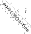
Figure 7 is an exploded, perspective view taken from a top, front, left side of a dual-clutch of the dual-clutch transmission ofFigure 3 ; -
Figure 8 is a longitudinal cross-sectional view of the dual-clutch and the input damper of the dual-clutch transmission ofFigure 3 ; -
Figure 9 is a perspective, longitudinal cross-sectional view of the clutch pack drum and the central clutch gear of the dual-clutch ofFigure 7 ; -
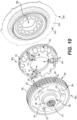
Figure 10 is an exploded, perspective view taken from a top, front, left side of the front clutch hub, front lubrication cover and front pressure plate of the dual-clutch ofFigure 7 ; -
Figure 11 is an exploded, perspective view taken from a rear, left side of the front clutch hub, front lubrication cover and front pressure plate of the dual-clutch ofFigure 7 ; -
Figure 12 is an exploded, perspective view taken from a top, front, left side of the rear pressure plate and rear clutch hub of the dual-clutch ofFigure 7 ; -
Figure 13A is a close-up view ofportion 13 ofFigure 8 , with the front and rear pressure plates abutting the central clutch gear of the dual-clutch ofFigure 7 ; -
Figure 13B is a close-up view ofportion 13 ofFigure 8 , with the front pressure plate being moved axially away from the central clutch gear of the dual-clutch ofFigure 7 , and with the rear pressure plate abutting the central clutch gear; -
Figure 13C is a close-up view ofportion 13 ofFigure 8 , with the rear pressure plate being moved axially away from the central clutch gear of the dual-clutch ofFigure 7 , and with the front pressure plate abutting the central clutch gear; and -
Figure 14 is a longitudinal cross-sectional view of a subtransmission of the dual-clutch transmission ofFigure 3 . - A dual-clutch transmission 100 (DCT) will be described herein with respect to a four-wheel side-by-side off-
road vehicle 20, but it is contemplated that the DCT 100 could be used in other types of vehicles such as, but not limited to, off-road vehicles having more or less than four wheels and/or more or less than two seats. The general features of the off-road vehicle 20 will be described with respect toFigures 1 and2 . - The
vehicle 20 has aframe 22, twofront wheels 24 connected to a front of theframe 22 byfront suspension assemblies 26 and tworear wheels 28 connected to theframe 22 by rear suspension assemblies 30 such as those described inUnited States Patent Serial No. 9,981,519 B2, dated May 29, 2018 front suspension assembly 26 has a frontshock absorber assembly 27 including ashock absorber 29 and aspring 31. Eachrear suspension assembly 30 has a rear shock absorber assembly 33 including ashock absorber 35 and aspring 37. Ground engaging members other thanwheels vehicle 20, such as tracks or skis. In addition, although four ground engaging members are illustrated in the Figures, thevehicle 20 could include more or less than four ground engaging members. Furthermore, different combinations of ground engaging members, such as tracks used in combination with skis, are contemplated. - The
frame 22 defines acentral cockpit area 42 inside which are disposed adriver seat 44 and apassenger seat 46. In the present implementation, thedriver seat 44 is disposed on the left side of thevehicle 20 and thepassenger seat 46 is disposed on the right side of thevehicle 20. However, it is contemplated that thedriver seat 44 could be disposed on the right side of thevehicle 20 and that thepassenger seat 46 could be disposed on the left side of thevehicle 20. As can be seen inFigure 1 , thevehicle 20 further has aseat belt 47 for each one of theseats steering wheel 48 is disposed in front of thedriver seat 44. Thesteering wheel 48 is used to turn thefront wheels 24 to steer thevehicle 20. Various displays andgauges 50 are disposed in front of thesteering wheel 48 to provide information to the driver regarding the operating conditions of thevehicle 20. Examples of displays andgauges 50 include, but are not limited to, a speedometer, a tachometer, a fuel gauge, a transmission position display, and an oil temperature gauge. - Referring to
Figure 2 , an internal combustion engine 52 (schematically shown inFigures 2 and3 ) is connected to theframe 22 in a rear portion of thevehicle 20. Theengine 52 has a crankshaft 53 (schematically shown inFigure 3 ) that is connected to theDCT 100 disposed behind the engine 52 (both schematically shown inFigure 2 ). The DCT 100 includes a subtransmission 700 (Figures 4 ,5 and14 ) operatively connected to a driveline 54 (schematically shown inFigure 2 ) of thevehicle 20 for operatively connecting the front andrear wheels engine 52 in order to propel thevehicle 20. A gear shifter 56 (Figure 2 ) located between theseats DCT 100 and thesubtransmission 700 of thevehicle 20, and enables the driver to select one of a plurality of gear configurations for operation of thevehicle 20. It is contemplated that paddle shifters (not shown) could be mounted to thesteering wheel 48 for enabling the driver to select a gear for operation of thevehicle 20. In the illustrated implementation of thevehicle 20, the gear configurations made available by the DCT 100 include a reverse gear, and forward first, second, third, fourth, fifth, sixth and seventh gear. The gear configurations made available by thesubtransmission 700 include park, neutral, high forward gears, and low forward gears. Thus, theDCT 100 and thesubtransmission 700 enable fourteen different forward-going gear configurations and two different reverse gear configurations. It is contemplated that the sequence and/or number of gear configurations could be different than as shown herein in other implementations. - A driving mode selector button 58 (
Figure 2 ) also enables the driver to select 2x4 or 4x4 operation of thevehicle 20. More particularly, thedriveline 54 includes afront propeller shaft 60 which extends horizontally to the left of theengine 52 towards a front differential assembly 62 (schematically shown inFigure 2 ). The frontdifferential assembly 62 is operatively connected to thefront wheels 24 via front wheel axle assemblies (not shown). The frontdifferential assembly 62 includes an electronic selector 64 (also schematically shown inFigure 2 ) operatively connected to the drivingmode selector button 58. Theelectronic selector 64 allows to selectively connect thefront propeller shaft 60 to the front wheel axle assemblies to enable 4x4 driving mode of thevehicle 20, or to selectively disconnect thefront propeller shaft 60 from the front wheel axle assemblies to enable 2x4 driving mode of the vehicle 20 (i.e. with only therear wheels 28 propelling the vehicle 20). - The
vehicle 20 further includes other components such as brakes, a radiator, headlights, and the like. As it is believed that these components would be readily recognized by one of ordinary skill in the art, further explanation and description of these components will not be provided herein. - Turning now to
Figures 3 to 14 , theDCT 100 will be described in more detail. TheDCT 100 includes ahousing 102 that is separate from theinternal combustion engine 52. Thehousing 102 is flanged to a rear face of theinternal combustion engine 52. In addition, thehousing 102 has a dedicated hydraulic and lubrication oil circuit, separated from that of theengine 52. A transmission fluid pump 104 (schematically shown inFigure 3 ) is received inside thehousing 102. Thetransmission fluid pump 104 is adapted to selectively pump oil-based fluids. Again, in the present implementation, thetransmission fluid pump 104 is separated from any other pump(s) theengine 52 may have. - Referring to
Figures 4 to 6 , theDCT 100 includes aninput damper 120 adapted to reduce the torque variations from thecrankshaft 53 to theDCT 100. Theinput damper 120 has ahollow shaft 122 definingsplines 124 for connection to the crankshaft 53 (as can be understood fromFigure 3 ). Thehollow shaft 122 has afront end 126 and arear end 128 defined consistently with the forward travel direction of the vehicle 20 (Figures 6 and8 ). Thehollow shaft 122 also defines aninput damper axis 130 about which thehollow shaft 122 rotates. Aninput member 140 is slidably engaged to thehollow shaft 122 and positioned between the front andrear ends input member 140 hassplines 141 complementary tosplines 124, and theinput member 140 can slide axially along theinput damper axis 130 between the front andrear ends input member 140 defines threerecesses 142 angularly displaced by about 120 degrees relative to theinput damper axis 130. Adisc spring assembly 150 is connected to thehollow shaft 122 and extends between the front andrear ends disc spring assembly 150 abuts ashoulder 152 of thehollow shaft 122 and biases theinput member 140 axially along theinput damper axis 130 towards therear end 128 of thehollow shaft 122. Anoutput member 160 is disposed over thehollow shaft 122 and positioned between theinput member 140 and therear end 128 of thehollow shaft 122. Theoutput member 160 is supported bybearings 162 disposed between theoutput member 160 and aconnector 164 disposed adjacent therear end 128 of thehollow shaft 122. Theconnector 164 retains theoutput member 160 on thehollow shaft 122. Theoutput member 160 defines threecams 166 also angularly displaced by about 120 degrees relative to the input damper axis 130 (Figure 6 ). The threecams 166 are structured and configured for engaging the corresponding threerecesses 142 of theinput member 140 when theinput member 140 is biased towards therear end 128 of thehollow shaft 122. Anoutput gear 170 is connected to theoutput member 160, and also rotates about theinput damper axis 130. Theoutput gear 170 has a plurality ofteeth 172. Apump gear 180 is connected to theoutput gear 170 via threefasteners 182, and extends between theoutput gear 170 and thedisc spring assembly 150. Thepump gear 180 also rotates about theinput damper axis 130. Thepump gear 180 is adapted to drive the transmission fluid pump 104 (Figure 2 ). Anauxiliary output gear 190 is connected to theoutput gear 170 via aring 191 havingcoil spring assemblies 192. Theauxiliary output gear 190 is biased by thecoil spring assemblies 192 and has a plurality ofteeth 194. In the present implementation, the number ofteeth 172 of theoutput gear 170 matches the number ofteeth 194 of theauxiliary output gear 190. Thecoil spring assemblies 192 permits angular displacements of theauxiliary output gear 190 about theinput damper axis 130 relative to theoutput gear 170. Theauxiliary output gear 190 provides preload on theteeth 172 of theoutput gear 170 and reduces backlash that can occur between theoutput gear 170 and a centralclutch gear 200 described below. - Referring to
Figures 4 to 8 , theDCT 100 includes a dual-clutch 202 having first andsecond clutches second clutches dual clutch 202 will be described. Thedual clutch 202 includes aclutch pack drum 220 that is adapted to rotate inside thehousing 102, and the centralclutch gear 200 is connected to theclutch pack drum 220 via fasteners 221 (Figures 7 and9 ). The centralclutch gear 200 hasteeth 212 adapted to mesh with theteeth output gear 170 and theauxiliary output gear 190. The centralclutch gear 200 is thus operatively connected to thecrankshaft 53 of theinternal combustion engine 52 via theinput damper 120. It is to be noted that having theinput damper 120 located outside theclutch pack drum 220 offers more flexibility to package theDCT 100 in the rear portion of theframe 22 of thevehicle 20 supporting theengine 52 and theDCT 100. Thus, having theinput damper 120 located outside theclutch pack drum 220 improves the overall packaging of theDCT 100 in the rear portion of thevehicle 20. Moreover, having theinput damper 120 located outside theclutch pack drum 220 allows for a greater angle of relative rotation between theinput member 140 and theoutput member 160 compared to an input damper that would be integrated in theclutch pack drum 220. The greater angle of relative rotation between theinput member 140 and theoutput member 160 improves the damping provided by theinput damper 120. - Referring to
Figures 7 and9 , the centralclutch gear 200 has afront face 212a and arear face 212b. The centralclutch gear 200 defines aclutch gear plane 214 and a clutchgear rotation axis 216 normal to the clutch gear plane 214 (Figure 8 ). It is to be appreciated that the clutchgear rotation axis 216 is parallel to theinput damper axis 130, and extends above and to the right of the input damper axis 130 (Figure 4 ). - Referring to
Figures 7 to 9 , theclutch pack drum 220 includes a frontclutch pack basket 222a disposed in front of the centralclutch gear 200, and a rearclutch pack basket 222b disposed behind the centralclutch gear 200. The front and rearclutch pack baskets fasteners 221 extending through the centralclutch gear 200. The front and rearclutch pack baskets clutch pack baskets clutch gear plane 214. The front and rearclutch pack baskets clutch pack baskets clutch gear plane 214, assists in reducing the manufacturing costs of theDCT 100. The front and rearclutch pack baskets cylindrical wall 226 definingsplines 228 and a plurality ofholes 230. - Turning now to
Figures 7 to 13C , the first clutch 204a will be described in details first. The operation of the first andsecond clutches DCT 100 will be described further below. A frontclutch pack 240a is received in theclutch pack basket 222a and is disposed in front of the centralclutch gear 200. Theclutch pack 240a includes a plurality ofclutch plates 242 havingteeth 244 extending away from the clutchgear rotation axis 216 and engaging thesplines 228 of theclutch pack basket 222a for rotating with the clutch pack drum 220 (Figure 13A ). Theclutch plates 242 are movable axially in a direction 246 (seedouble arrow 246 inFigures 13A to 13C ) defined by the clutchgear rotation axis 216. Theclutch plates 242 have disc surfaces including relatively low friction material. The frontclutch pack 240a further includes a plurality ofclutch disks 250 disposed alternatingly with theclutch plates 242 in the direction 246 (Figure 13A ). Theclutch disks 250 have disc surfaces including a relatively high friction material. Theclutch disks 250 haveteeth 254 extending towards the clutchgear rotation axis 216. Theclutch disks 250 are also movable axially in thedirection 246 defined by the clutchgear rotation axis 216. As will become apparent from the description below, when theclutch disks 250 are selectively engaged by theclutch plates 242, theclutch disks 250 rotate with theclutch pack drum 220. - Referring to
Figures 7 ,10 and11 , a frontclutch hub 260a is received in theclutch pack 240a and is disposed in front of the centralclutch gear 200. Theclutch hub 260a definessplines 262 structured to engage with theteeth 254 of theclutch disks 250 of theclutch pack 240a. Theclutch disks 250 are movable axially relative to theclutch hub 260a in thedirection 246 defined by the clutchgear rotation axis 216 as theteeth 254 slide axially in thesplines 262. When theclutch disks 250 are selectively engaged by theclutch plates 242, theclutch hub 260a rotates with theclutch pack drum 220. Theclutch hub 260a has threearms 264 connecting arim portion 266 of theclutch hub 260a (defining the splines 262) to acentral portion 268 of theclutch hub 260a.Holes 270 are defined in each of thearms 264 for receiving fasteners 272 (Figure 13A ). Thecentral portion 268 definessplines 274. Referring toFigures 10 ,11 and13A , a plurality ofbores 280 are defined in thecentral portion 268, in thearms 264 and in therim portion 266. Thebores 280 are adapted for allowing flow of fluid therethrough, as will become apparent from the following description. - Referring to
Figures 10 and11 , alubrication cover 300a is also received in theclutch pack 240a. Thelubrication cover 300a is disposed in front of the centralclutch gear 200 and behind the frontclutch hub 260a. Thelubrication cover 300a defines a plurality ofapertures 302 on arim portion 304 thereof. Three threadedholes 306 are defined in thelubrication cover 300a for receiving thefasteners 272. When thefasteners 272 extend through theholes 270 of theclutch hub 260a and are engaged in the threadedholes 306 of thelubrication cover 300a, thelubrication cover 300a and theclutch hub 260a are interconnected.Passages 310 are defined in thelubrication cover 300a and extend around each one of the threaded holes 306. Thepassages 310 are adapted for allowing flow of fluid therethrough, as will become apparent from the following description. - Referring to
Figures 7 ,10 ,11 and13A , theDCT 100 further includes apressure plate 320a disposed in front of the centralclutch gear 200. Thepressure plate 320a is disposed between the centralclutch gear 200 and thelubrication cover 300a. Aring 322a is connected to the centralclutch gear 200, andcoil spring assemblies 324a interconnect thepressure plate 320a to the centralclutch gear 200. Thepressure plate 320a rotates with the centralclutch gear 200, and is movable axially in thedirection 246 upon compression and extension of thecoil spring assemblies 324a. Thepressure plate 320a has afront face 332a (Figure 10 ) including arim portion 334a. Therim portion 334a of thepressure plate 320a is structured to selectively engage theclutch plate 242 that is closest to the centralclutch gear 200. Thepressure plate 320a further has arear face 342a (Figure 11 ) where sixpads 344 project therefrom. Thepads 344 are structured for abutting thefront face 212a of the centralclutch gear 200 and to leave a spacing between thefront face 212a of the centralclutch gear 200 and therear face 342a of thepressure plate 320a (the spacing is shown inFigure 13A ). Referring toFigures 13A to 13C , achamber 350a is defined between thefront face 212a of the centralclutch gear 200 and therear face 342a of thepressure plate 320a.Seals 352 are disposed between thepressure plate 320a and the centralclutch gear 200 to prevent fluid from escaping thechamber 350a through the regions where theseals 352 extend. Thepressure plate 320a further defines apressure plate passage 360a extending between thefront face 332a and therear face 342a. More particularly, thepressure plate passage 360a starts on therear face 342a from one of the pads 344 (Figure 11 ). Thepressure plate passage 360a is adapted for allowing flow of fluid therethrough, as will become apparent from the following description. - Referring to
Figures 4 ,8 , and13A , ashaft 400a is connected to the frontclutch hub 260a via teeth (not shown) engaging thesplines 274 ofcentral portion 268. Theshaft 400a is coaxial with the clutchgear rotation axis 216. Theshaft 400a defines threepassages 410, 412 (Figure 13A ), and 414 (Figure 8 ) adapted for flowing fluid therethrough. A manifold 420 (Figure 8 ) is connected to the front portion of theshaft 400a. The manifold 420 fluidly connects thetransmission fluid pump 104 to thepassages passages shaft 400a (Figure 4 ). Referring toFigures 4 ,5 and14 , a plurality of transmission gears 600 are operatively connected to theshaft 400a. The transmission gears 600 include the gears corresponding to thefirst gear 601,third gear 603,fifth gear 605, andseventh gear 607 of theDCT 100. The transmission gears 600 are all disposed behind the centralclutch gear 200. - Arrows show the flow of fluid through the dual-
clutch 202 inFigures 10 ,11 ,13A and13B when the dual-clutch 202 rotates. When fluid is selectively supplied in thepassage 410 from thetransmission fluid pump 104, fluid flows through theshaft 400a in the passage 410 (Figure 13A ), throughpassages 430a defined in the central clutch gear 200 (Figures 9 and13A ) and into thechamber 350a. Since thepads 344 abut thefront face 212a of the centralclutch gear 200, fluid flows through the spacing between thepressure plate 320a and the centralclutch gear 200, and fills thechamber 350a. Thepads 344 are thus structured for selectively allowing flow of fluid from thepassage 410 to thechamber 350a. When the fluid is selectively supplied with sufficient pressure by thetransmission fluid pump 104, the pressurized fluid in thechamber 350a overcomes the biasing force of thecoil spring assemblies 324a and moves thepressure plate 320a axially away from the central clutch gear 200 (i.e. forward of the central clutch gear 200), as shown betweenFigures 13A and13B . Thepressure plate 320a selectively squeezes theclutch plates 242 and theclutch disks 250 together for engaging theclutch plates 242 with theclutch disks 250. The frontclutch hub 260a and thelubrication cover 300a are thus rotatable with theclutch pack drum 220 and the centralclutch gear 200, and theshaft 400a drives the transmission gears 600 corresponding to thefirst gear 601,third gear 603,fifth gear 605 andseventh gear 607 of theDCT 100. - Referring to
Figure 13B , as some of the fluid escapes thechamber 350a through thepressure plate passage 360a (as shown by the arrows inFigure 13B ), fluid flows in the frontclutch pack 240a and lubricates and cools theclutch plates 242, theclutch disks 250, and theclutch pack basket 222a, as shown by arrows inFigure 13B . Fluid flows through theholes 230 of theclutch pack basket 222a, is collected in thehousing 102 and is returned to thetransmission fluid pump 104 for recirculation in theDCT 100. It is thus to be understood that in order for thepressure plate 320a to selectively squeeze theclutch pack 240a, pressurized fluid is continuously supplied in thechamber 350a by thetransmission fluid pump 104. - Referring to
Figure 13A , when fluid is selectively supplied in the passage 414 (Figure 8 ) and as the first clutch 204a rotates, fluid flows through theshaft 400a, through thebores 280 defined in thecentral portion 268, in thearms 264 and in therim portion 266 of the frontclutch hub 260a, and through theaperture 302 andpassages 310 defined in thelubrication cover 300a, and on to the frontclutch pack 240a, as shown by arrows inFigure 13A . The fluid flowing through thepassage 414 provides additional lubrication and cooling to theclutch plates 242, theclutch disks 250, and theclutch pack basket 222a of the first clutch 204a. Since the first clutch 204a is operatively connected to thetransmission gear 600 corresponding to thefirst gear 601 of theDCT 100, which can have a heavy usage, for example, when thevehicle 20 launches repetitively, additional lubrication and cooling to the first clutch 204a provided by fluid flowing through thepassage 414 and thebore 280 is advantageous under certain conditions. - Referring to
Figures 7 ,8 and12 , the second clutch 204b will now be described. A rearclutch pack 240b is received in theclutch pack basket 222b and is disposed behind the centralclutch gear 200. The rearclutch pack 240b also includes a plurality ofclutch plates 242 havingteeth 244 extending away from the clutchgear rotation axis 216 and engaging thesplines 228 of theclutch pack basket 222b for rotating with the clutch pack drum 220 (Figures 13A to 13C ). In the present implementations, the front and rearclutch packs DCT 100. Theclutch plates 242 have disc surfaces including a relatively low friction material. The rearclutch pack 240b further includes a plurality ofclutch disks 250 disposed alternatingly with theclutch plates 242 in the direction 246 (Figure 13A ). Theclutch disks 250 have disc surfaces including a relatively high friction material. Theclutch disks 250 haveteeth 254 extending towards the clutch gear rotation axis 216 (Figures 13A to 13C ). Theclutch disks 250 are also movable axially in thedirection 246 defined by the clutchgear rotation axis 216. - Referring to
Figures 7 and12 , a rearclutch hub 260b is received in theclutch pack 240b and is disposed behind the centralclutch gear 200. Theclutch hub 260b also definessplines 262 structured to engage with theteeth 254 of theclutch disks 250 of theclutch pack 240b. Theclutch disks 250 are movable axially relative to theclutch hub 260b in the direction 246 (Figures 13A to 13C ). When theclutch disks 250 are selectively engaged by theclutch plates 242, theclutch hub 260b rotates with theclutch pack drum 220. Theclutch hub 260b has eightarms 264 connecting arim portion 266 of theclutch hub 260b to thecentral portion 268 of theclutch hub 260b. Thecentral portion 268 definessplines 274. Referring toFigure 12 , a plurality ofbores 280 are also defined in thecentral portion 268, in thearms 264 and in therim portion 266 of theclutch hub 260b. Thebores 280 are adapted for allowing flow of fluid therethrough, as will become apparent from the following description. - Referring to
Figures 7 and12 , theDCT 100 further includes apressure plate 320b disposed behind the centralclutch gear 200. Thepressure plate 320b is disposed between the centralclutch gear 200 and theclutch hub 260b. Aring 322b (Figure 7 ) is connected to the centralclutch gear 200, andcoil spring assemblies 324b interconnect thepressure plate 320b to the centralclutch gear 200. It is to be noted that therings spring assemblies DCT 100. Thepressure plate 320b rotates with the centralclutch gear 200, and is movable axially in thedirection 246 upon compression and extension of thecoil spring assemblies 324b. Thepressure plate 320b has arear face 332b including arim portion 334b. Therim portion 334b of thepressure plate 320a is structured to selectively engage theclutch plate 242 of the rearclutch pack 240b that is closest to the centralclutch gear 200. Thepressure plate 320b further has afront face 342b where sixpads 344 project therefrom. Thepads 344 are structured for abutting therear face 212b of the centralclutch gear 200 and to leave a spacing defined between therear face 212b of the centralclutch gear 200 and thefront face 342b of thepressure plate 320b (Figure 13A ). Achamber 350b is defined between therear face 212b of the centralclutch gear 200 and thefront face 342b of thepressure plate 320b.Seals 352 are also disposed between thepressure plate 320b and the centralclutch gear 200 to prevent fluid from escaping thechamber 350b through the regions where theseals 352 extend. Thepressure plate 320b further defines apressure plate passage 360b (Figure 12 ) extending between therear face 332b and thefront face 342b. More particularly, thepressure plate passage 360b starts on thefront face 342b from one of thepads 344. Thepressure plate passage 360b is adapted for allowing flow of fluid therethrough, as will become apparent from the following description. - It is to be appreciated that in the illustrated implementation, the
pressure plates pressure plates clutch gear plane 214.. These features assist in reducing the manufacturing costs of theDCT 100. Furthermore, there is no component similar to thelubrication cover 300a in the second clutch 204b. - Referring to
Figures 13A to 13C , arrows show the flow of fluid through the dual-clutch 202 when the dual-clutch 202 rotates and fluid is selectively supplied in thepassages passage 412 of theshaft 400a, fluid flows through theshaft 400a in the passage 412 (Figure 13A and13C ), throughpassages 430b defined in the central clutch gear 200 (Figure 9 ) and into thechamber 350b. Since thepads 344 abut therear face 212b of the centralclutch gear 200, fluid flows through the spacing between thepressure plate 320b and the centralclutch gear 200, and fills thechamber 350b. Thepads 344 are thus structured for selectively allowing flow of fluid from thepassage 412 to thechamber 350b. When the fluid is selectively supplied with sufficient pressure, the pressurized fluid in thechamber 350b overcomes the biasing force of thecoil spring assemblies 324b and moves thepressure plate 320b axially away from the central clutch gear 200 (i.e. rearward of the central clutch gear 200), as shown betweenFigures 13A and13C . Thepressure plate 320b selectively squeezes theclutch plates 242 and theclutch disks 250 together for engaging theclutch plates 242 with theclutch disks 250. The rearclutch hub 260b is thus rotatable with theclutch pack drum 220 and the centralclutch gear 200. As some of the fluid escapes thechamber 350b through thepressure plate passage 360b, fluid flows in the rearclutch pack 240b and lubricates and cools theclutch plates 242, theclutch disks 250, and theclutch pack basket 222b, as shown by arrows inFigure 13C . Fluid flows through theholes 230 of theclutch pack basket 222b, is collected in thehousing 102 and is returned to thetransmission fluid pump 104 for recirculation in theDCT 100. It is thus to be understood that in order for thepressure plate 320b to selectively squeeze theclutch pack 240b, pressurized fluid is continuously supplied by thetransmission fluid pump 104. - Furthermore, it is to be noted that in the
DCT 100 of the present technology, having the centralclutch gear 200 between thepressure plates chambers clutch gear 200, assists in distributing the forces more evenly in theclutch pack drum 220. This feature also assists in reducing the rotating masses in theclutch pack drum 220. - Referring to
Figure 8 , ahollow shaft 400b is connected to the rearclutch hub 260b via thesplines 274 defined in thecentral portion 268 thereof. Theshaft 400a extends through theshaft 400b. Another plurality of transmission gears 600 are operatively connected to theshaft 400b. Referring toFigure 5 , the transmission gears 600 include the gears corresponding to thesecond gear 602, fourth gear 604 andsixth gear 606 of theDCT 100, and the transmission gears 600 are also disposed behind the centralclutch gear 200. - Referring back to
Figures 4 and5 , theDCT 100 further includes alayshaft 610 having additional transmission gears 601', 603', 605', 607' operatively connected thereto. Each of the transmission gears 601', 603', 605', 607' on thelayshaft 610 is selected to have a gear ratio with the correspondingtransmission gear DCT 100. TheDCT 100 further includes anotherlayshaft 620 having additional transmission gears (not shown) operatively connected thereto. Each of the transmission gears on thelayshaft 620 is selected to have a gear ratio with the correspondingtransmission gear DCT 100. Thelayshaft 620 further includes thetransmission gear 608 corresponding to a reverse gear of theDCT 100. Anoutput gear 630 is operatively connected to each of thelayshafts subtransmission 700. TheDCT 100 further includes synchronizers, shift actuators and shift forks adapted to preselect an odd transmission gear on theshaft 400a while thevehicle 20 is being driven in an even transmission gear on theshaft 400b (and vice versa), and thus enable the driver to operate transmission gear changes when the driver operates thegear shifter 56. - Referring now to
Figures 4 ,5 and14 , thesubtransmission 700 will be described in more details. Thesubtransmission 700 has aninput shaft 702. Aninput gear 704 is operatively connected to theinput shaft 702 via anoutput damper 710. Theinput gear 704 is selectively driven by theoutput gear 630 of thelayshaft 610, or by theoutput gear 630 of thelayshaft 620, depending on the transmission gear that is selected. Theoutput damper 710 is operatively connected between theinput gear 704 and the input shat 702. Theoutput damper 710 has components similar to theinput damper 120, and can reduce backlash that can occur between thedriveline 54 of thevehicle 20 and theDCT 100. Aparking lock gear 720 is operatively connected to theinput shaft 702, and is adapted to lock thesubtransmission 700, and thus thevehicle 20, when selected. Thesubtransmission 700 further includes ahigh transmission gear 730 and alow transmission gear 732 operatively connected to theinput shaft 702. - The
subtransmission 700 further includes anoutput shaft 740 configured for operative connection to thedriveline 54 of the vehicle 20 (as shown byarrow 54 inFigures 4 ,5 and14 ). Theoutput shaft 740 includes a high transmission gear 730' and a low transmission gear 732' operatively connected thereto. When thesubtransmission 700 is in the high gear configuration (i.e. when thehigh transmission gear 730 drives the high transmission gear 730'), a first gear ratio is defined between theinput shaft 702 and theoutput shaft 740. When thesubtransmission 700 is in the low gear configuration (i.e. when thelow transmission gear 732 drives the low transmission gear 732'), a second gear ratio is defined between theinput shaft 702 and theoutput shaft 740. The first gear ratio (i.e. high gear ratio) is smaller than the second gear ratio (i.e. low gear ratio). The driver can thus select in which mode thesubtransmission 700 is to be configured, i.e. between high gear ratio and low gear ratio, depending on the terrain on which thevehicle 20 travels, for example. - The
output shaft 740 further has abevel gear 750 defined in the rear portion thereof. Thebevel gear 750 is adapted to operatively connect to arear transaxle 751 of thevehicle 20 for driving the rear wheels 28 (as indicated byarrows 28 onFigure 4 ). A frontpropeller shaft gear 752 is operatively connected to theoutput shaft 740, and is adapted to engage with a front propeller shaft gear 752' operatively connected to thefront propeller shaft 60. As mentioned above, thefront propeller shaft 60 selectively drives thefront wheels 24 when the driver selects 4x4 operation of thevehicle 20.
Claims (16)
- A dual-clutch transmission (100) for use in a vehicle (20) having an internal combustion engine (52) and a driveline (54), the internal combustion engine having a crankshaft (53), the dual-clutch transmission comprising:a housing (102);a clutch pack drum (220) adapted to rotate inside the housing;a central clutch gear (200) connected to the clutch pack drum, the central clutch gear defining a clutch gear plane (214) and a clutch gear rotation axis (216) normal to the clutch gear plane;a first clutch pack (240a) received in the clutch pack drum on a first side of the central clutch gear, the first clutch pack including:at least one first clutch plate (242) engaging and rotating with the clutch pack drum; andat least one first clutch disk (250) selectively engaged by the at least one first clutch plate, the at least one first clutch plate and the at least one first clutch disk being disposed alternatingly in a direction (246) defined by the clutch gear rotation axis;a first clutch hub (260a) received in the first clutch pack, the first clutch hub engaging and rotating with the at least one first clutch disk;a first pressure plate (320a) disposed on the first side of the central clutch gear, the first pressure plate rotating with the central clutch gear, the first pressure plate selectively squeezing the at least one first clutch plate and the at least one first clutch disk together for engaging the at least one first clutch disk with the at least one first clutch plate;a first shaft (400a) connected to the first clutch hub, the first shaft being rotatable about the clutch gear rotation axis;at least one first transmission gear (600) operatively connected to the first shaft such that the at least one first transmission gear is rotatable about the clutch gear rotation axis, the first shaft driving the at least one first transmission gear in response to the first pressure plate being moved axially to squeeze the at least one first clutch plate and the at least one first clutch disk together;a second clutch pack (240b) received in the clutch pack drum on a second side of the central clutch gear, the second side of the central clutch gear being opposite the first side of the central clutch gear, the second clutch pack including:at least one second clutch plate (242) engaging and rotating with the clutch pack drum; andat least one second clutch disk (250) selectively engaged by the at least one second clutch plate, the at least one second clutch plate and the at least one second clutch disk being disposed alternatingly in the direction defined by the clutch gear rotation axis;a second clutch hub (260b) received in the second clutch pack, the second clutch hub engaging and rotating with the at least one second clutch disk;a second pressure plate (320b) disposed on the second side of the central clutch gear, the second pressure plate rotating with the central clutch gear, the second pressure plate selectively squeezing the at least one second clutch plate and the at least one second clutch disk together for engaging the at least one second clutch disk with the at least one second clutch plate;a second shaft (400b) connected to the second clutch hub, the second shaft being coaxial with the first shaft such that the second shaft is rotatable about the clutch gear rotation axis;at least one second transmission gear (600) operatively connected to the second shaft such that the at least one second transmission gear is rotatable about the clutch gear rotation axis, the second shaft driving the at least one second transmission gear in response to the second pressure plate being moved axially to squeeze the at least one second clutch plate and the at least one second clutch disk together; andan output shaft (740) configured for operative connection to the driveline of the vehicle, the output shaft being operatively connected to and driven by:the at least one first transmission gear in response to the first pressure plate being moved axially to squeeze the at least one first clutch plate and the at least one first clutch disk together; andthe at least one second transmission gear in response to the second pressure plate being moved axially to squeeze the at least one second clutch plate and the at least one second clutch disk together,characterized in thatan input damper (120) is configured to be operatively connected to the crankshaft, the input damper being located outside the clutch pack drum;the central clutch gear being driven by the input damper via a plurality of teeth of the central clutch gear such that the input damper is configured to operatively connect the central clutch gear to the crankshaft.
- The dual-clutch transmission of claim 1, wherein the first pressure plate is symmetrical to the second pressure plate about the clutch gear plane.
- The dual-clutch transmission of claim 1, wherein the first pressure plate is identical to the second pressure plate.
- The dual-clutch transmission of claim 1, wherein the input damper comprises:a hollow shaft (122) defining splines (124) adapted for connection to the crankshaft, the hollow shaft having first and second ends (126, 128);an input member (140) slidably engaged to the hollow shaft and positioned between the first and second ends, the input member defining at least one recess (142);a disc spring assembly (150) connected to the hollow shaft and biasing the input member towards the second end;an output member (160) disposed over the hollow shaft and positioned between the input member and the second end of the hollow shaft, the output member defining at least one cam (166) structured and configured for engaging the at least one recess of the input member; andan output gear (170) connected to the output member, the output gear engaging and driving the central clutch gear.
- The dual-clutch transmission of claim 4, further comprising a pump gear (180) operatively connected to the output member of the input damper, the pump gear being adapted to drive a transmission fluid pump (104).
- The dual-clutch transmission of claim 1, wherein the first shaft defines:a first passage (410) adapted for supplying fluid to a first chamber (350a) defined between the central clutch gear and the first pressure plate, anda second passage (412) adapted for supplying fluid to a second chamber (350b) defined between the central clutch gear and the second pressure plate.
- The dual-clutch transmission of claim 6, wherein the first shaft further defines a third passage (414) adapted for selectively supplying fluid to the clutch pack drum.
- The dual-clutch transmission of claim 7, wherein the first clutch hub has a plurality of bores (280) defined therein adapted for supplying fluid from the third passage of the first shaft to the clutch pack drum.
- The dual-clutch transmission of claim 6, wherein each of the first and second pressure plates has a pressure plate passage (360a, 360b) defined therein for supplying fluid from the first shaft to the clutch pack drum.
- The dual-clutch transmission of claim 1, wherein:the clutch pack drum includes a first clutch pack basket (222a) disposed on the first side of the central clutch gear, and a second clutch pack basket (222b) disposed on the second side of the central clutch gear;the first clutch pack is received in the first clutch pack basket;the second clutch pack is received in the second clutch pack basket; andthe first clutch pack basket is symmetrical to the second clutch pack basket about the clutch gear plane.
- The dual-clutch transmission of claim 1, wherein:the clutch pack drum includes a first clutch pack basket disposed on the first side of the central clutch gear, and a second clutch pack basket disposed on the second side of the central clutch gear;the first clutch pack is received in the first clutch pack basket;the second clutch pack is received in the second clutch pack basket; andthe first clutch pack basket is identical to the second clutch pack basket.
- The dual-clutch transmission of claim 1, further comprising a subtransmission (700) having an input shaft (702) being configured for operative connection to the first and second shafts, and the output shaft (740) configured for operative connection to the driveline of the vehicle, the subtransmission having a high gear configuration and a low gear configuration;when the subtransmission is in the high gear configuration, a first gear ratio is defined between the input shaft and the output shaft; andwhen the subtransmission is in the low gear configuration, a second gear ratio is defined between the input shaft and the output shaft, the first gear ratio being smaller than the second gear ratio.
- The dual-clutch transmission of claim 12, wherein the subtransmission further comprises:an input gear (704), andan output damper (710) operatively connected between the input gear and the input shaft of the subtransmission.
- The dual-clutch transmission of claim 1, wherein the second shaft is hollow and the first shaft extends through the second shaft.
- The dual-clutch transmission of claim 14, wherein:the second shaft is operatively connected to the at least one second transmission gear on the second side of the central clutch gear; andthe first shaft is operatively connected to the at least one first transmission gear on the second side of the central clutch gear.
- A vehicle comprising:a frame;an engine connected to the frame;the dual-clutch transmission of any one of claims 1 to 15 operatively connected to the engine; anda driveline operatively connected to the dual-clutch transmission.
Applications Claiming Priority (2)
| Application Number | Priority Date | Filing Date | Title |
|---|---|---|---|
| US202062968323P | 2020-01-31 | 2020-01-31 | |
| PCT/EP2021/052271 WO2021152167A1 (en) | 2020-01-31 | 2021-02-01 | Dual-clutch transmission |
Publications (2)
| Publication Number | Publication Date |
|---|---|
| EP4097375A1 EP4097375A1 (en) | 2022-12-07 |
| EP4097375B1 true EP4097375B1 (en) | 2023-07-19 |
Family
ID=74505258
Family Applications (1)
| Application Number | Title | Priority Date | Filing Date |
|---|---|---|---|
| EP21702991.7A Active EP4097375B1 (en) | 2020-01-31 | 2021-02-01 | Dual-clutch transmission |
Country Status (3)
| Country | Link |
|---|---|
| US (1) | US12066081B2 (en) |
| EP (1) | EP4097375B1 (en) |
| WO (1) | WO2021152167A1 (en) |
Families Citing this family (6)
| Publication number | Priority date | Publication date | Assignee | Title |
|---|---|---|---|---|
| US11614028B2 (en) | 2020-12-21 | 2023-03-28 | Brp-Rotax Gmbh & Co. Kg | Turbocharger and turbine wheel for a turbine of a turbocharger |
| WO2023099503A1 (en) * | 2021-11-30 | 2023-06-08 | Brp-Rotax Gmbh & Co. Kg | Dual-clutch transmission |
| CN118786070A (en) * | 2022-01-29 | 2024-10-15 | 庞巴迪动力产品公司 | Powertrain layout of off-road vehicles |
| CA3202482A1 (en) | 2022-06-30 | 2023-12-30 | Bombardier Recreational Products Inc. | Vehicle having a continuously variable transmission |
| CA3202484A1 (en) | 2022-06-30 | 2023-12-30 | Bombardier Recreational Products Inc. | Method for operating a vehicle having a dual-clutch transmission |
| US20240003412A1 (en) * | 2022-06-30 | 2024-01-04 | Bombardier Recreational Products Inc. | Vehicle having a continuously variable transmission |
Citations (4)
| Publication number | Priority date | Publication date | Assignee | Title |
|---|---|---|---|---|
| US3040408A (en) * | 1959-02-03 | 1962-06-26 | Rockwell Standard Co | Lift truck shift |
| US3254541A (en) * | 1963-07-15 | 1966-06-07 | Rockwell Standard Co | Compact multi-speed forward and reverse transmission |
| US20170167550A1 (en) * | 2015-12-09 | 2017-06-15 | Honda Motor Co., Ltd. | Internal combustion engine |
| US9981519B2 (en) * | 2015-01-29 | 2018-05-29 | Bombardier Recreational Products Inc. | Rear suspension assembly for an off-road vehicle |
Family Cites Families (10)
| Publication number | Priority date | Publication date | Assignee | Title |
|---|---|---|---|---|
| US3791500A (en) * | 1972-04-05 | 1974-02-12 | Dab Ind Inc | Fluid activated double-acting clutch with fluid metering means |
| CA990974A (en) * | 1973-08-27 | 1976-06-15 | Clark Equipment Company | Power transmission |
| US4570503A (en) * | 1984-09-17 | 1986-02-18 | Caterpillar Tractor Co. | Countershaft transmission |
| US4726246A (en) * | 1986-10-01 | 1988-02-23 | Caterpillar Inc. | Countershaft transmission having two forward and two reverse speeds |
| US5188575A (en) * | 1988-04-29 | 1993-02-23 | Leising Maurice B | Automatic four-speed transmission with interconnected clutches |
| JP3891823B2 (en) * | 2001-10-31 | 2007-03-14 | 本田技研工業株式会社 | transmission |
| DE502004004086D1 (en) * | 2004-06-17 | 2007-07-26 | Borgwarner Inc | Back plate for a double clutch in axially parallel design |
| ATE549491T1 (en) * | 2007-09-29 | 2012-03-15 | Honda Motor Co Ltd | POWER UNIT FOR SMALL VEHICLES |
| JP6132300B2 (en) * | 2013-03-28 | 2017-05-24 | 本田技研工業株式会社 | Clutch control device in power unit for vehicle |
| JP6195315B2 (en) * | 2015-07-31 | 2017-09-13 | 本田技研工業株式会社 | Clutch hydraulic control circuit |
-
2021
- 2021-02-01 EP EP21702991.7A patent/EP4097375B1/en active Active
- 2021-02-01 US US17/796,075 patent/US12066081B2/en active Active
- 2021-02-01 WO PCT/EP2021/052271 patent/WO2021152167A1/en not_active Ceased
Patent Citations (4)
| Publication number | Priority date | Publication date | Assignee | Title |
|---|---|---|---|---|
| US3040408A (en) * | 1959-02-03 | 1962-06-26 | Rockwell Standard Co | Lift truck shift |
| US3254541A (en) * | 1963-07-15 | 1966-06-07 | Rockwell Standard Co | Compact multi-speed forward and reverse transmission |
| US9981519B2 (en) * | 2015-01-29 | 2018-05-29 | Bombardier Recreational Products Inc. | Rear suspension assembly for an off-road vehicle |
| US20170167550A1 (en) * | 2015-12-09 | 2017-06-15 | Honda Motor Co., Ltd. | Internal combustion engine |
Also Published As
| Publication number | Publication date |
|---|---|
| EP4097375A1 (en) | 2022-12-07 |
| WO2021152167A1 (en) | 2021-08-05 |
| US12066081B2 (en) | 2024-08-20 |
| US20230258245A1 (en) | 2023-08-17 |
Similar Documents
| Publication | Publication Date | Title |
|---|---|---|
| EP4097375B1 (en) | Dual-clutch transmission | |
| US7587957B2 (en) | Multiple-ratio dual clutch vehicle transmission | |
| US10221897B2 (en) | Dual clutch arrangement with two piece main rotating manifold | |
| US8967352B2 (en) | Low driven inertia dual clutch | |
| EP3405700B1 (en) | Dual clutch transaxle | |
| US20200018361A1 (en) | Dual clutch with cooling distribution reservoir chambers | |
| CN101156004A (en) | Power Flow Configuration of Dual Clutch Transmission Mechanism | |
| US4858495A (en) | Multi-speed powershift transmission | |
| US9656547B2 (en) | Vehicle | |
| US4498356A (en) | Motor vehicle transmission | |
| US4446758A (en) | Planetary transmission | |
| JP3989811B2 (en) | Transmission with auxiliary transmission mechanism | |
| US20250109790A1 (en) | Method for controlling an automatic transmission of a vehicle | |
| WO2019084089A1 (en) | Invertible reversible multi-application gearbox | |
| US3542176A (en) | Multiple range power transmission mechanism | |
| EP1577583A1 (en) | Automatic speed changer | |
| EP4441396B1 (en) | DUAL CLUTCH GEARBOX | |
| KR102282517B1 (en) | Transmission of agriculture vehicle | |
| JP2001105905A (en) | Power shift transmission | |
| WO2006056804A1 (en) | Twin layshaft manual transmission | |
| JP4581569B2 (en) | Four-wheel drive vehicle power train | |
| WO2005085683A1 (en) | Gear selector and transmission | |
| RU2352476C1 (en) | Gearbox |
Legal Events
| Date | Code | Title | Description |
|---|---|---|---|
| STAA | Information on the status of an ep patent application or granted ep patent |
Free format text: STATUS: UNKNOWN |
|
| STAA | Information on the status of an ep patent application or granted ep patent |
Free format text: STATUS: THE INTERNATIONAL PUBLICATION HAS BEEN MADE |
|
| PUAI | Public reference made under article 153(3) epc to a published international application that has entered the european phase |
Free format text: ORIGINAL CODE: 0009012 |
|
| STAA | Information on the status of an ep patent application or granted ep patent |
Free format text: STATUS: REQUEST FOR EXAMINATION WAS MADE |
|
| 17P | Request for examination filed |
Effective date: 20220829 |
|
| AK | Designated contracting states |
Kind code of ref document: A1 Designated state(s): AL AT BE BG CH CY CZ DE DK EE ES FI FR GB GR HR HU IE IS IT LI LT LU LV MC MK MT NL NO PL PT RO RS SE SI SK SM TR |
|
| GRAP | Despatch of communication of intention to grant a patent |
Free format text: ORIGINAL CODE: EPIDOSNIGR1 |
|
| STAA | Information on the status of an ep patent application or granted ep patent |
Free format text: STATUS: GRANT OF PATENT IS INTENDED |
|
| DAV | Request for validation of the european patent (deleted) | ||
| DAX | Request for extension of the european patent (deleted) | ||
| INTG | Intention to grant announced |
Effective date: 20230221 |
|
| GRAS | Grant fee paid |
Free format text: ORIGINAL CODE: EPIDOSNIGR3 |
|
| GRAA | (expected) grant |
Free format text: ORIGINAL CODE: 0009210 |
|
| STAA | Information on the status of an ep patent application or granted ep patent |
Free format text: STATUS: THE PATENT HAS BEEN GRANTED |
|
| AK | Designated contracting states |
Kind code of ref document: B1 Designated state(s): AL AT BE BG CH CY CZ DE DK EE ES FI FR GB GR HR HU IE IS IT LI LT LU LV MC MK MT NL NO PL PT RO RS SE SI SK SM TR |
|
| REG | Reference to a national code |
Ref country code: GB Ref legal event code: FG4D |
|
| REG | Reference to a national code |
Ref country code: CH Ref legal event code: EP |
|
| REG | Reference to a national code |
Ref country code: DE Ref legal event code: R096 Ref document number: 602021003626 Country of ref document: DE |
|
| REG | Reference to a national code |
Ref country code: IE Ref legal event code: FG4D |
|
| REG | Reference to a national code |
Ref country code: LT Ref legal event code: MG9D |
|
| REG | Reference to a national code |
Ref country code: NL Ref legal event code: MP Effective date: 20230719 |
|
| PG25 | Lapsed in a contracting state [announced via postgrant information from national office to epo] |
Ref country code: NL Free format text: LAPSE BECAUSE OF FAILURE TO SUBMIT A TRANSLATION OF THE DESCRIPTION OR TO PAY THE FEE WITHIN THE PRESCRIBED TIME-LIMIT Effective date: 20230719 |
|
| PG25 | Lapsed in a contracting state [announced via postgrant information from national office to epo] |
Ref country code: GR Free format text: LAPSE BECAUSE OF FAILURE TO SUBMIT A TRANSLATION OF THE DESCRIPTION OR TO PAY THE FEE WITHIN THE PRESCRIBED TIME-LIMIT Effective date: 20231020 |
|
| PG25 | Lapsed in a contracting state [announced via postgrant information from national office to epo] |
Ref country code: IS Free format text: LAPSE BECAUSE OF FAILURE TO SUBMIT A TRANSLATION OF THE DESCRIPTION OR TO PAY THE FEE WITHIN THE PRESCRIBED TIME-LIMIT Effective date: 20231119 |
|
| PG25 | Lapsed in a contracting state [announced via postgrant information from national office to epo] |
Ref country code: SE Free format text: LAPSE BECAUSE OF FAILURE TO SUBMIT A TRANSLATION OF THE DESCRIPTION OR TO PAY THE FEE WITHIN THE PRESCRIBED TIME-LIMIT Effective date: 20230719 Ref country code: RS Free format text: LAPSE BECAUSE OF FAILURE TO SUBMIT A TRANSLATION OF THE DESCRIPTION OR TO PAY THE FEE WITHIN THE PRESCRIBED TIME-LIMIT Effective date: 20230719 Ref country code: PT Free format text: LAPSE BECAUSE OF FAILURE TO SUBMIT A TRANSLATION OF THE DESCRIPTION OR TO PAY THE FEE WITHIN THE PRESCRIBED TIME-LIMIT Effective date: 20231120 Ref country code: NO Free format text: LAPSE BECAUSE OF FAILURE TO SUBMIT A TRANSLATION OF THE DESCRIPTION OR TO PAY THE FEE WITHIN THE PRESCRIBED TIME-LIMIT Effective date: 20231019 Ref country code: LV Free format text: LAPSE BECAUSE OF FAILURE TO SUBMIT A TRANSLATION OF THE DESCRIPTION OR TO PAY THE FEE WITHIN THE PRESCRIBED TIME-LIMIT Effective date: 20230719 Ref country code: LT Free format text: LAPSE BECAUSE OF FAILURE TO SUBMIT A TRANSLATION OF THE DESCRIPTION OR TO PAY THE FEE WITHIN THE PRESCRIBED TIME-LIMIT Effective date: 20230719 Ref country code: IS Free format text: LAPSE BECAUSE OF FAILURE TO SUBMIT A TRANSLATION OF THE DESCRIPTION OR TO PAY THE FEE WITHIN THE PRESCRIBED TIME-LIMIT Effective date: 20231119 Ref country code: HR Free format text: LAPSE BECAUSE OF FAILURE TO SUBMIT A TRANSLATION OF THE DESCRIPTION OR TO PAY THE FEE WITHIN THE PRESCRIBED TIME-LIMIT Effective date: 20230719 Ref country code: GR Free format text: LAPSE BECAUSE OF FAILURE TO SUBMIT A TRANSLATION OF THE DESCRIPTION OR TO PAY THE FEE WITHIN THE PRESCRIBED TIME-LIMIT Effective date: 20231020 Ref country code: FI Free format text: LAPSE BECAUSE OF FAILURE TO SUBMIT A TRANSLATION OF THE DESCRIPTION OR TO PAY THE FEE WITHIN THE PRESCRIBED TIME-LIMIT Effective date: 20230719 |
|
| PG25 | Lapsed in a contracting state [announced via postgrant information from national office to epo] |
Ref country code: PL Free format text: LAPSE BECAUSE OF FAILURE TO SUBMIT A TRANSLATION OF THE DESCRIPTION OR TO PAY THE FEE WITHIN THE PRESCRIBED TIME-LIMIT Effective date: 20230719 |
|
| REG | Reference to a national code |
Ref country code: AT Ref legal event code: UEP Ref document number: 1589771 Country of ref document: AT Kind code of ref document: T Effective date: 20230719 |
|
| REG | Reference to a national code |
Ref country code: DE Ref legal event code: R097 Ref document number: 602021003626 Country of ref document: DE |
|
| PG25 | Lapsed in a contracting state [announced via postgrant information from national office to epo] |
Ref country code: ES Free format text: LAPSE BECAUSE OF FAILURE TO SUBMIT A TRANSLATION OF THE DESCRIPTION OR TO PAY THE FEE WITHIN THE PRESCRIBED TIME-LIMIT Effective date: 20230719 |
|
| PG25 | Lapsed in a contracting state [announced via postgrant information from national office to epo] |
Ref country code: SM Free format text: LAPSE BECAUSE OF FAILURE TO SUBMIT A TRANSLATION OF THE DESCRIPTION OR TO PAY THE FEE WITHIN THE PRESCRIBED TIME-LIMIT Effective date: 20230719 Ref country code: RO Free format text: LAPSE BECAUSE OF FAILURE TO SUBMIT A TRANSLATION OF THE DESCRIPTION OR TO PAY THE FEE WITHIN THE PRESCRIBED TIME-LIMIT Effective date: 20230719 Ref country code: ES Free format text: LAPSE BECAUSE OF FAILURE TO SUBMIT A TRANSLATION OF THE DESCRIPTION OR TO PAY THE FEE WITHIN THE PRESCRIBED TIME-LIMIT Effective date: 20230719 Ref country code: EE Free format text: LAPSE BECAUSE OF FAILURE TO SUBMIT A TRANSLATION OF THE DESCRIPTION OR TO PAY THE FEE WITHIN THE PRESCRIBED TIME-LIMIT Effective date: 20230719 Ref country code: DK Free format text: LAPSE BECAUSE OF FAILURE TO SUBMIT A TRANSLATION OF THE DESCRIPTION OR TO PAY THE FEE WITHIN THE PRESCRIBED TIME-LIMIT Effective date: 20230719 Ref country code: CZ Free format text: LAPSE BECAUSE OF FAILURE TO SUBMIT A TRANSLATION OF THE DESCRIPTION OR TO PAY THE FEE WITHIN THE PRESCRIBED TIME-LIMIT Effective date: 20230719 Ref country code: SK Free format text: LAPSE BECAUSE OF FAILURE TO SUBMIT A TRANSLATION OF THE DESCRIPTION OR TO PAY THE FEE WITHIN THE PRESCRIBED TIME-LIMIT Effective date: 20230719 |
|
| PLBE | No opposition filed within time limit |
Free format text: ORIGINAL CODE: 0009261 |
|
| STAA | Information on the status of an ep patent application or granted ep patent |
Free format text: STATUS: NO OPPOSITION FILED WITHIN TIME LIMIT |
|
| 26N | No opposition filed |
Effective date: 20240422 |
|
| PG25 | Lapsed in a contracting state [announced via postgrant information from national office to epo] |
Ref country code: SI Free format text: LAPSE BECAUSE OF FAILURE TO SUBMIT A TRANSLATION OF THE DESCRIPTION OR TO PAY THE FEE WITHIN THE PRESCRIBED TIME-LIMIT Effective date: 20230719 |
|
| PG25 | Lapsed in a contracting state [announced via postgrant information from national office to epo] |
Ref country code: MC Free format text: LAPSE BECAUSE OF FAILURE TO SUBMIT A TRANSLATION OF THE DESCRIPTION OR TO PAY THE FEE WITHIN THE PRESCRIBED TIME-LIMIT Effective date: 20230719 |
|
| REG | Reference to a national code |
Ref country code: CH Ref legal event code: PL |
|
| PG25 | Lapsed in a contracting state [announced via postgrant information from national office to epo] |
Ref country code: LU Free format text: LAPSE BECAUSE OF NON-PAYMENT OF DUE FEES Effective date: 20240201 |
|
| PG25 | Lapsed in a contracting state [announced via postgrant information from national office to epo] |
Ref country code: CH Free format text: LAPSE BECAUSE OF NON-PAYMENT OF DUE FEES Effective date: 20240229 |
|
| PG25 | Lapsed in a contracting state [announced via postgrant information from national office to epo] |
Ref country code: LU Free format text: LAPSE BECAUSE OF NON-PAYMENT OF DUE FEES Effective date: 20240201 Ref country code: CH Free format text: LAPSE BECAUSE OF NON-PAYMENT OF DUE FEES Effective date: 20240229 |
|
| PG25 | Lapsed in a contracting state [announced via postgrant information from national office to epo] |
Ref country code: BG Free format text: LAPSE BECAUSE OF FAILURE TO SUBMIT A TRANSLATION OF THE DESCRIPTION OR TO PAY THE FEE WITHIN THE PRESCRIBED TIME-LIMIT Effective date: 20230719 |
|
| PG25 | Lapsed in a contracting state [announced via postgrant information from national office to epo] |
Ref country code: BG Free format text: LAPSE BECAUSE OF FAILURE TO SUBMIT A TRANSLATION OF THE DESCRIPTION OR TO PAY THE FEE WITHIN THE PRESCRIBED TIME-LIMIT Effective date: 20230719 |
|
| REG | Reference to a national code |
Ref country code: BE Ref legal event code: MM Effective date: 20240229 |
|
| PG25 | Lapsed in a contracting state [announced via postgrant information from national office to epo] |
Ref country code: BE Free format text: LAPSE BECAUSE OF NON-PAYMENT OF DUE FEES Effective date: 20240229 |
|
| PG25 | Lapsed in a contracting state [announced via postgrant information from national office to epo] |
Ref country code: FR Free format text: LAPSE BECAUSE OF NON-PAYMENT OF DUE FEES Effective date: 20240229 |
|
| PG25 | Lapsed in a contracting state [announced via postgrant information from national office to epo] |
Ref country code: IE Free format text: LAPSE BECAUSE OF NON-PAYMENT OF DUE FEES Effective date: 20240201 |
|
| PG25 | Lapsed in a contracting state [announced via postgrant information from national office to epo] |
Ref country code: IE Free format text: LAPSE BECAUSE OF NON-PAYMENT OF DUE FEES Effective date: 20240201 Ref country code: FR Free format text: LAPSE BECAUSE OF NON-PAYMENT OF DUE FEES Effective date: 20240229 Ref country code: BE Free format text: LAPSE BECAUSE OF NON-PAYMENT OF DUE FEES Effective date: 20240229 |
|
| PG25 | Lapsed in a contracting state [announced via postgrant information from national office to epo] |
Ref country code: CY Free format text: LAPSE BECAUSE OF FAILURE TO SUBMIT A TRANSLATION OF THE DESCRIPTION OR TO PAY THE FEE WITHIN THE PRESCRIBED TIME-LIMIT; INVALID AB INITIO Effective date: 20210201 |
|
| PG25 | Lapsed in a contracting state [announced via postgrant information from national office to epo] |
Ref country code: HU Free format text: LAPSE BECAUSE OF FAILURE TO SUBMIT A TRANSLATION OF THE DESCRIPTION OR TO PAY THE FEE WITHIN THE PRESCRIBED TIME-LIMIT; INVALID AB INITIO Effective date: 20210201 |
|
| GBPC | Gb: european patent ceased through non-payment of renewal fee |
Effective date: 20250201 |
|
| PG25 | Lapsed in a contracting state [announced via postgrant information from national office to epo] |
Ref country code: TR Free format text: LAPSE BECAUSE OF FAILURE TO SUBMIT A TRANSLATION OF THE DESCRIPTION OR TO PAY THE FEE WITHIN THE PRESCRIBED TIME-LIMIT Effective date: 20230719 |
|
| PG25 | Lapsed in a contracting state [announced via postgrant information from national office to epo] |
Ref country code: GB Free format text: LAPSE BECAUSE OF NON-PAYMENT OF DUE FEES Effective date: 20250201 |
|
| PGFP | Annual fee paid to national office [announced via postgrant information from national office to epo] |
Ref country code: DE Payment date: 20260220 Year of fee payment: 6 |
|
| PGFP | Annual fee paid to national office [announced via postgrant information from national office to epo] |
Ref country code: AT Payment date: 20260218 Year of fee payment: 6 |
|
| PGFP | Annual fee paid to national office [announced via postgrant information from national office to epo] |
Ref country code: IT Payment date: 20260220 Year of fee payment: 6 |