EP4097352B1 - Anordnung mit einem ersten und einem zweiten element und einem verbinder und verfahren zur montage solch einer anordnung - Google Patents
Anordnung mit einem ersten und einem zweiten element und einem verbinder und verfahren zur montage solch einer anordnung Download PDFInfo
- Publication number
- EP4097352B1 EP4097352B1 EP21703781.1A EP21703781A EP4097352B1 EP 4097352 B1 EP4097352 B1 EP 4097352B1 EP 21703781 A EP21703781 A EP 21703781A EP 4097352 B1 EP4097352 B1 EP 4097352B1
- Authority
- EP
- European Patent Office
- Prior art keywords
- connector
- channel
- relative
- actuator
- end position
- Prior art date
- Legal status (The legal status is an assumption and is not a legal conclusion. Google has not performed a legal analysis and makes no representation as to the accuracy of the status listed.)
- Active
Links
Images


Classifications
-
- F—MECHANICAL ENGINEERING; LIGHTING; HEATING; WEAPONS; BLASTING
- F03—MACHINES OR ENGINES FOR LIQUIDS; WIND, SPRING, OR WEIGHT MOTORS; PRODUCING MECHANICAL POWER OR A REACTIVE PROPULSIVE THRUST, NOT OTHERWISE PROVIDED FOR
- F03D—WIND MOTORS
- F03D13/00—Assembly, mounting or commissioning of wind motors; Arrangements specially adapted for transporting wind motor components
- F03D13/20—Arrangements for mounting or supporting wind motors; Masts or towers for wind motors
- F03D13/25—Arrangements for mounting or supporting wind motors; Masts or towers for wind motors specially adapted for offshore installation
-
- E—FIXED CONSTRUCTIONS
- E02—HYDRAULIC ENGINEERING; FOUNDATIONS; SOIL SHIFTING
- E02B—HYDRAULIC ENGINEERING
- E02B17/00—Artificial islands mounted on piles or like supports, e.g. platforms on raisable legs or offshore constructions; Construction methods therefor
- E02B17/0004—Nodal points
-
- E—FIXED CONSTRUCTIONS
- E02—HYDRAULIC ENGINEERING; FOUNDATIONS; SOIL SHIFTING
- E02B—HYDRAULIC ENGINEERING
- E02B17/00—Artificial islands mounted on piles or like supports, e.g. platforms on raisable legs or offshore constructions; Construction methods therefor
- E02B17/02—Artificial islands mounted on piles or like supports, e.g. platforms on raisable legs or offshore constructions; Construction methods therefor placed by lowering the supporting construction to the bottom, e.g. with subsequent fixing thereto
- E02B17/027—Artificial islands mounted on piles or like supports, e.g. platforms on raisable legs or offshore constructions; Construction methods therefor placed by lowering the supporting construction to the bottom, e.g. with subsequent fixing thereto steel structures
-
- E—FIXED CONSTRUCTIONS
- E04—BUILDING
- E04H—BUILDINGS OR LIKE STRUCTURES FOR PARTICULAR PURPOSES; SWIMMING OR SPLASH BATHS OR POOLS; MASTS; FENCING; TENTS OR CANOPIES, IN GENERAL
- E04H12/00—Towers; Masts or poles; Chimney stacks; Water-towers; Methods of erecting such structures
- E04H12/02—Structures made of specified materials
- E04H12/08—Structures made of specified materials of metal
- E04H12/085—Details of flanges for tubular masts
-
- F—MECHANICAL ENGINEERING; LIGHTING; HEATING; WEAPONS; BLASTING
- F03—MACHINES OR ENGINES FOR LIQUIDS; WIND, SPRING, OR WEIGHT MOTORS; PRODUCING MECHANICAL POWER OR A REACTIVE PROPULSIVE THRUST, NOT OTHERWISE PROVIDED FOR
- F03D—WIND MOTORS
- F03D13/00—Assembly, mounting or commissioning of wind motors; Arrangements specially adapted for transporting wind motor components
- F03D13/10—Assembly of wind motors; Arrangements for erecting wind motors
-
- F—MECHANICAL ENGINEERING; LIGHTING; HEATING; WEAPONS; BLASTING
- F03—MACHINES OR ENGINES FOR LIQUIDS; WIND, SPRING, OR WEIGHT MOTORS; PRODUCING MECHANICAL POWER OR A REACTIVE PROPULSIVE THRUST, NOT OTHERWISE PROVIDED FOR
- F03D—WIND MOTORS
- F03D13/00—Assembly, mounting or commissioning of wind motors; Arrangements specially adapted for transporting wind motor components
- F03D13/20—Arrangements for mounting or supporting wind motors; Masts or towers for wind motors
-
- E—FIXED CONSTRUCTIONS
- E02—HYDRAULIC ENGINEERING; FOUNDATIONS; SOIL SHIFTING
- E02B—HYDRAULIC ENGINEERING
- E02B17/00—Artificial islands mounted on piles or like supports, e.g. platforms on raisable legs or offshore constructions; Construction methods therefor
- E02B2017/0039—Methods for placing the offshore structure
- E02B2017/0043—Placing the offshore structure on a pre-installed foundation structure
-
- E—FIXED CONSTRUCTIONS
- E02—HYDRAULIC ENGINEERING; FOUNDATIONS; SOIL SHIFTING
- E02B—HYDRAULIC ENGINEERING
- E02B17/00—Artificial islands mounted on piles or like supports, e.g. platforms on raisable legs or offshore constructions; Construction methods therefor
- E02B2017/0056—Platforms with supporting legs
- E02B2017/0065—Monopile structures
-
- E—FIXED CONSTRUCTIONS
- E02—HYDRAULIC ENGINEERING; FOUNDATIONS; SOIL SHIFTING
- E02B—HYDRAULIC ENGINEERING
- E02B17/00—Artificial islands mounted on piles or like supports, e.g. platforms on raisable legs or offshore constructions; Construction methods therefor
- E02B2017/0091—Offshore structures for wind turbines
-
- Y—GENERAL TAGGING OF NEW TECHNOLOGICAL DEVELOPMENTS; GENERAL TAGGING OF CROSS-SECTIONAL TECHNOLOGIES SPANNING OVER SEVERAL SECTIONS OF THE IPC; TECHNICAL SUBJECTS COVERED BY FORMER USPC CROSS-REFERENCE ART COLLECTIONS [XRACs] AND DIGESTS
- Y02—TECHNOLOGIES OR APPLICATIONS FOR MITIGATION OR ADAPTATION AGAINST CLIMATE CHANGE
- Y02E—REDUCTION OF GREENHOUSE GAS [GHG] EMISSIONS, RELATED TO ENERGY GENERATION, TRANSMISSION OR DISTRIBUTION
- Y02E10/00—Energy generation through renewable energy sources
- Y02E10/70—Wind energy
- Y02E10/72—Wind turbines with rotation axis in wind direction
-
- Y—GENERAL TAGGING OF NEW TECHNOLOGICAL DEVELOPMENTS; GENERAL TAGGING OF CROSS-SECTIONAL TECHNOLOGIES SPANNING OVER SEVERAL SECTIONS OF THE IPC; TECHNICAL SUBJECTS COVERED BY FORMER USPC CROSS-REFERENCE ART COLLECTIONS [XRACs] AND DIGESTS
- Y02—TECHNOLOGIES OR APPLICATIONS FOR MITIGATION OR ADAPTATION AGAINST CLIMATE CHANGE
- Y02E—REDUCTION OF GREENHOUSE GAS [GHG] EMISSIONS, RELATED TO ENERGY GENERATION, TRANSMISSION OR DISTRIBUTION
- Y02E10/00—Energy generation through renewable energy sources
- Y02E10/70—Wind energy
- Y02E10/727—Offshore wind turbines
Definitions
- the present invention relates to an assembly, comprising a first and a second member, and a connector to connect the first and second member relative to each other.
- the invention further relates to a method of assembling such an assembly of a first and a second member that each comprise at least one through hole.
- the present invention is particularly suitable for offshore applications, e.g. for connecting a wind turbine to a monopile, a wind turbine to a transition piece, a transition piece to a monopile, between members of a monopile or wind turbine, as well as to connections having a much smaller diameter than monopiles, e.g. between members of a jacket.
- the members of such assemblies are provided with flanges which are connected using bolts of significant size.
- M72 bolts are used for connecting a wind turbine tower to a monopile or transition piece.
- these bolts are electrically tightened with 8.000 Nm.
- the preload is increased with hydraulic tools to 22.000 Nm.
- the bolts itself are heavy and the tools for tightening the bolts are also heavy and hard to handle.
- the bolts are arranged all around the circumference of the flanges, leaving only a very limited gap between adjacent bolts.
- a connection using flanges with bolts is insufficiently scalable to meet the ever increasing demands resulting from even larger wind turbines and greater depths at sea where they are installed.
- a human worker could insert a connector as described in PCT/IB2019/056792 into the channel to an end position in a first step, followed by a further step of consecutively expanding said connector radially relative to said channel, to thereby connect the first and second member relative to each other.
- the connector could be accurately and easily placed in the channel by a user with very limited hassle or force. Only when the connector is placed in its desired end position, it is expanded in the channel to connect the first and second member relative to each other.
- Use of a connector according to the invention also makes specially machined contact surfaces with an inclination corresponding to an inclination of the radially displaceable actuator redundant.
- US 2008/080946 A1 is directed to an expansion pin system for construction of a wind turbine structural tower, and is considered the closest prior art. Relative to US 2008/080946 A1 , at least the characterizing features of the independent claims are novel.
- US 2008/080946 A1 discloses, in terminology of the present invention, a first and a second member, wherein the second member has a fork-shaped cross section with a main body and two substantially parallel walls that each comprise at least one through hole, wherein the first member is arranged between the two walls of the second member, having the through hole, and wherein said through hole of the first member and the through holes of the second member are aligned to define a channel.
- the expansion pin may be interpreted as a connector that is axially insertable in said channel to an end position and consecutively expandable radially relative to said channel, to connect the first and second member relative to each other.
- the expansion pin system When the expansion pin system is inserted into the channel it results in an alignment of the through holes of the first and the second member.
- the United States patent US 4,684,280 discloses a configuration that shows some similarity to US 2008/080946 A1 .
- the second member has a fork-shaped cross section with a main body and two substantially parallel walls that each comprise at least one through hole, wherein the first member is arranged between the two walls of the second member, having the through hole, and wherein said through hole of the first member and the through holes of the second member are aligned to define a channel.
- a clevis bushing may be interpreted as a connector that is axially insertable in said channel to an end position and consecutively expandable radially relative to said channel. This clevis bushing, upon radially expansion thereof, clamps itself in a through hole of one wall of the fork-shaped second member, and furthermore presses the first member in axial direction against the other wall of the fork-shaped second member.
- An object of the present invention is to provide an assembly, that is improved relative to the prior art. Said object is achieved with the assembly according to claim 1 of the present invention, comprising:
- an actuator that is configured to move the connector in an axial direction relative to the channel, there is no need for a human worker to enter inside one of the respective first or second members, when the connectors are arranged from the inside, or to perform a hazardous diving operation when the connectors are arranged from the outside.
- the actuator by virtue of replacing a human worker, allows for an increased level of automation and therefore a reduction in construction time.
- automated insertion and expanding of the actuator a controlled and repeatable force may be applied.
- automated actuation also allows multiple connectors to be expanded simultaneously, thereby further reducing construction time and moreover allowing for an even application of a clamping contact that causes the pre-tensioned connection between the first member and the second member.
- the actuator allows the connector or connectors to be arranged in an assembly of first and second members that are too small for a human worker to fit in, especially if the connections are submerged and the human worker requires diving equipment.
- Such an assembly may be present in jacket construction, wherein tubular members may have diameters as small as 1 to 3 meter.
- the actuator is configured to consecutively:
- the assembly further comprises a stop configured to set the end position of the connector relative to said channel.
- Said stop may comprise an abutment that is configured to abut against one of the first member and the second member, and may alternatively, or additionally, be defined by a maximum elongation or displacement of the actuator.
- the connector in the expanded state thereof, pushes against faces of the through holes of the second member that are directed away from the main body thereof to define the pre-tensioned connection between the first member and the second member.
- the through hole of the first member in the expanded state of the connector, wherein the connection between the first member and the second member is pre-tensioned, is arranged at an offset relative to the through holes in the second member.
- said through hole of the first member and the through holes of the second member define a channel, which means that said through holes are positioned in a way that they are "substantially" aligned.
- a presence of an offset may guarantee that there always remains a slight misalignment of the through hole of the first member relative to the through holes of the second member. This is advantageous, because the offset, i.e. the slight misalignment in the channel, guarantees that the connection between the first member and the second member may be optimally pre-tensioned.
- the connector is configured to expand in the channel, wherein the connector pushes the first member against the main body of the second member.
- the side of the connector that is directed towards the main body does not come into contact with the inner walls of the through holes in the parallel walls of the second member. In this way, the side of the connector that is directed towards the main body can fully transfer its compressive force to the first member that is pressed towards and against the main body of the second member to obtain the desired pre-tensioning.
- the connector comprises:
- the invention is furthermore directed to a method of assembling a first and a second member that are tubular members of a wind turbine support structure and each comprise at least one through hole, wherein the second member has a fork-shaped cross section with a main body arranged between two substantially parallel walls that each comprise at least one through hole, said method comprising the steps of:
- the step of inserting the connector into the channel to the end position comprises the steps of:
- the actuator thus replaces a human worker and allows the connector to be inserted and expanded from a single, first side.
- This may be from an inside of the tubular member, but may also be from an outside of the tubular member. However, one side suffices, and consequently the channel formed by the through holes of the first and second members needs to be accessible from one side only.
- the step of consecutively expanding said connector radially relative to said channel comprises:
- the method further comprises the step of setting the end position of the connector relative to said channel by a stop.
- the step of moving said connector in the axial direction in said channel by the actuator is performed until the connector reaches its end position as defined by the stop, and the step of consecutively expanding said connector radially relative to said channel is performed upon further actuation of the actuator once the connecter has reached its end position.
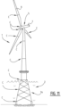
- FIG. 1 An example of an offshore construction comprising multiple connections C where an assembly according to the invention may be applied is shown in Figure 1 .
- An offshore wind turbine tower 1 is supported by a supporting base structure 2 which is in Figure 1 embodied as a monopile 3 with a transition piece 4.
- the skilled person will understand that similar connections are present for alternative supporting base structures 2, such as in a jacket construction 34 as shown in Figure 11 .
- the connections C may be applied between separate members 8 of the monopile 3, between the monopile 3 and the transition piece 4, between the transition piece 4 and the turbine tower 1, between members 9 of the turbine tower 1, and between a rotor blade 6 and a hub of a rotor, or even between different parts of a rotor blade 6.
- the construction proposed by the present invention does not require a human worker to enter a space inside a tubular member anymore, allowing the assembly to be applied for connecting (tubular) members of a relatively limited size, such as in jacket constructions.
- the connections C may serve to connect a jacket to a foundation, e.g. pre-piled foundation piles, drilled foundation piles or suction buckets. It may also be used to provide a jacket to jacket connection.
- a wind turbine 5 will be oriented such that the rotor blades 6 are optimally driven by the available wind power.
- the rotor blades 6 drive a (not shown) generator in the nacelle 7, wherein the generator generates electricity.
- the wind turbine 5 causes alternating loads on any connection C in the construction, and dependent on the wind direction, specific parts of the connection C have to absorb most of the loads.
- the assembly according to the invention comprises the first member 10 and a second member 11, wherein the second member 11 has a fork-shaped cross section 15 with a main body 16 arranged between two substantially parallel walls 17 that each comprise at least one through hole 12, 13, 14.
- the first member 10 is arranged between the two walls 17 of the second member 11, having the through hole 13, 14.
- Said through hole 12 of the first member 10 and the through holes 13, 14 of the second member 11 define a channel 18.
- the assembly further comprises a connector 19 that is axially insertable in said channel 18 to an end position ( Figures 3B and 7 ) and consecutively expandable radially relative to said channel 18 ( Figure 8 ), to connect the first member 10 and the second member 11 relative to each other.
- the connector 19 comprises a compacted state (shown in Figures 3A , 3B , 5-7 and 12 ), wherein the connector 19 has a size that is freely insertable into and out of the channel 18, and a connecting state (e.g. shown in Figures 8 and 9 ) wherein the connector 19 is expanded in the channel 18 to connect the first 10 and second member 11 relative to each other.
- An actuator 20 is configured to move said connector 19 in an axial direction in said channel 18.
- the assembly according to the present invention comprises a first member 10 and a second member 11, each comprising at least one through hole 12-14.
- the through holes 12-14 may be directly arranged in the first member 10 and the second member 11, and consequently prior art flanges are redundant. This has several advantages, one of them being a saving of material and less weight outside the line of travel of forces through the assembly.
- an actuator 20 that is configured to move the connector 19 in an axial direction relative to the channel 18, there is no need for a human worker to enter inside one of the respective first or second members 10, 11.
- the actuator 20 by virtue of replacing a human worker, allows for an increased level of automation and therefore a reduction in construction time.
- automated insertion and expanding of the actuator 20 a controlled and repeatable force may be applied.
- automated actuation also allows multiple connectors 19 to be expanded simultaneously, thereby further reducing construction time and moreover allowing for a uniform application of a clamping contact that causes the pre-tensioned connection between the first member 10 and the second member 11.
- the actuator 20 allows the connector 19 to be arranged in an assembly of first and second members 10, 11 that are too small for a human worker to fit in.
- Such an assembly may be present in jacket construction, wherein tubular members may have diameters as small as 1 to 3 meter, and may be impossible to access, either because of their limited size, or e.g. for safety reasons or because they are submerged.
- human workers would have to carry diving equipment, requiring additional space that is not present in tubular members with such small diameters.
- a taper angle at the top of first member 10 allows for a certain amount of ovality in either member 10 or 11 to be forced back into a round shape under the force of gravity by pushing first member 10 into second member 11.
- a similar taper shape may be present at the ends of one or both of the walls 17 of the fork-shaped cross section 15 of the second member 11.
- the assembly shown in the Figures further comprises a stop 21 configured to set the end position of the connector 19 relative to said channel 18.
- the stop 21 may comprise an abutment 22 that is configured to abut against one of the first member 10 and the second member 11.
- the stop 21 may be defined by a maximum elongation or displacement of the actuator 20.
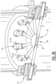
- a clamping device 23 is arranged inside first and second members 10, 11 having a tubular shape and a significantly smaller diameter than the monopile shown in Figure 2 .
- the limited diameter of the tubular first and second members 10, 11 shown in Figures 3A and 3B may be in the order of 1-3 meter, i.e. too small for a human worker to enter and work in.
- the first and second members 10, 11 shown in Figures 3A , 3B and 4-8 may be part of a jacket construction.
- the connectors 19 are each positioned in front of an associated channel 18.
- Figure 3B shows that the connectors 19 are each moved by the actuator 20 inside their associated channels 18, wherein the connectors 19 are each positioned in an end position in their associated channels as defined by the stop 21.
- the stop 21 is here embodied as an abutment 22 abutting against an inner one of walls 17 of the second member 11.
- the connector 19 comprises at least one expansion block 24 and at least one wedge 25, wherein the actuator 20 is configured to displace the wedge 25 relative to the expansion block 24.
- the wedge 25 has an inclined surface 26 facing the at least one expansion block 24.
- stop 21 is arranged on the at least one expansion block 24, it may prevent the expansion block to be inserted fully inside the channel 18.
- the stop 21,which may be embodied as abutment 22, may thus define an end position of the connector 19 relative to said channel 18 ( Figure 3B ).
- first and the second member 10, 11 each comprise at least one through hole 12, 13, 14, wherein the second member 11 has a fork-shaped cross section 15 with a main body 16 arranged between two substantially parallel walls 17 that each comprise at least one through hole 13, 14.
- the method of assembling starts with the step of arranging the first member 10 between the two walls 17 of the second member 11 ( Figure 4 ).
- the next step is positioning the through holes 12, 13, 14 of the first member 10 and the second member 11 to define a channel 18 ( Figure 5).
- Figure 5 also shows that a clamping device 23 is inserted inside the second member 11 and brought to a position wherein the connectors 19 of said clamping device 23 substantially align with associated channels 18 ( Figure 6 ).
- the next step comprises the step of inserting a connector 19 into the channel 18 to an end position ( Figure 7 ), which is performed by moving said connector 19 in an axial direction in said channel 18 by the actuator 20 ( Figure 7 ).
- said connector 19 is expanded radially relative to said channel 18, to thereby connect the first member 10 and the second member 11 relative to each other, the expanded connector 19 pushing the first member 10 against a face 27 of the main body 16 of the second member 11 to define a clamping contact and thereby a pre-tensioned connection between a face 28 of the first member 10 and the face 27 of the main body 16 of the second member 11.
- Figure 7 shows the step of setting the end position of the connector 19 relative to said channel 18 by the stop 21.
- the stop 21, which is embodied as an abutment 22, abuts against an inner one of the walls 17 of the fork-shaped second member 11, thereby preventing the expansion block 24 to move further inside said channel 18.
- the step of moving said connector 19 in the axial direction in said channel 18 by the actuator 20 is performed until the connector 19 reaches its end position as defined by the stop ( Figure 7 ).
- the step of consecutively expanding said connector 19 radially relative to said channel 18 is performed upon further actuation of the actuator 20 once the connecter 19 has reached its end position.
- Figure 8 shows how the expansion block 24 is stopped by the stop 21, while the wedge 25 is pushed further relative to said channel 18 by the actuator 20.
- the expansion block 24 is moved in a radial direction relative to said channel 18 until the clamping contact and thereby the pre-tensioned connection between the face 28 of the first member 10 and the face 27 of the main body 16 of the second member 11 is obtained.
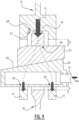
- Figure 9 The clamping contact and resulting pre-tensioned connection between the first member 10 and the second member 11 is now further explained by Figure 9 . It is explicitly mentioned that this explanation relates to the orientation shown in Figure 9 , but the skilled person will understand the same principle may also be applied in other orientations, such as transverse or upside down relative to Figure 9 .
- the connector 19 contacts at its lower side with faces 29 formed at the lower side of the respective through holes 13, 14 of the second member 11.
- the upper side of the connector 19 contacts a face 30 that is arranged at the upper side of the through hole 12 in the first member 10.
- the connector 19 pushes faces 29 of the second member 11 away from face 30 of the first member 10.
- the through hole 12 of the first member 10 is arranged at an offset O or offsets O, relative to the through holes 13, 14 in the second member 11.
- the assembly may comprise one or more than one further connector 19, wherein the actuator 20 is arranged between the connector 19 and the one or more than one further connector 19, wherein each of the connector 19 and the one or more than one further connector 19 is inserted into its own channel 18.
- the preferred embodiment shown in the Figures comprises a total of twelve connectors 19, of which five are shown in full and two are shown intersected. Multiple channels 18 and associated connectors 19 are arranged along a circumference of the first 10 and the second member 11.
- the actuator 20 is preferably configured to simultaneously move said connector 19 and at least one or more than one further connector 19 in an axial direction of their associated channels 18. Automated actuation using actuator 20 also allows multiple connectors 29 to be expanded simultaneously, thereby further reducing construction time and moreover allowing for a uniform application of a clamping contact that causes the pre-tensioned connection between the first member 10 and the second member 11.
- the actuator 20 may be arranged in a clamping device 23.
- the actuator 20 may comprise one or more than one hydraulic cylinder 31.
- the shown embodiment comprises twelve hydraulic cylinders 31, i.e. one for each connector 19.
- a common pressure supply 32 may be configured to move said hydraulic cylinders 31 simultaneously.
- the expansion block 24 has a surface 33 of which at least a portion is a contact surface with the wedge 25 having an orientation corresponding with the inclined surface 26 of said wedge 25.
- the inclined surface 26 of said wedge 25 may comprises an inclination with an angle of less than 15° relative to a displacement direction of said wedge 25.
- the relatively small value of the radial force component is typically less than the friction at the contact surface between wedge 25 and clamping block 24, resulting in a self-locking contact between the wedge 25 and the clamping block 24 in the connecting state.
- the wedge 25 remains in place even if the actuator 20 for originally displacing the wedge 25 would be loosened or even removed. In this way, a reliable and fail-safe assembly is provided.
- first member 10 and the second member 11 are overlapping tubular members and the through holes 12, 13, 14 are radially aligned relative to the tubular members to define the channel 18 that is radially extending.
- Said channel 18 may have an elongate cross section extending in a longitudinal direction of at least one of said first member 10 and said second member 11.
- the first member 10 and the second member 11 may have longitudinal axes that are at least parallel, and that preferably coincide.
- a symmetrical force transmission may be obtained if, according to the shown preferred embodiment, the second member 11 has a fork-shaped cross section 15 with a main body 16 and two substantially parallel walls 17 that each comprises at least one through hole.
- the first member 18 is arranged between the two walls 17 of the second member 11, having the through holes 13, 14, and said through hole 12 of the first member 10 and the through holes 13, 14 of the second member 11 are positioned to define the channel 18.
- the arrows in Figure 9 indicate how a clamping force F c is symmetrically distributed.
- the axial clamping force F c is interpreted as a value 100%, directed in the axial direction of the assembly, i.e. in the axial direction of the first member 10 and the second member 11.
- a required actuation force F a of tens to several hundreds of tons is needed.
- This force that is in the axial direction of the channel 23 will be used to overcome the friction force in interfaces 29 and 26 and to generate a clamping force F c .
- the friction forces are typically between 5-20% of their load perpendicular to the friction plane (friction coefficient of 0.05 - 0.2). With an assumed friction coefficient of 10% at both surfaces 29 and 26, the horizontal actuating force required to overcome this friction force is 20% of the preload F cd .
- the inclined plane will result in a force amplification of the load F app that is applied in the axial direction of the channel. This causes the clamping force F c .
- F c high preload
- the axial force applied on wedge 25 would be 100 tons than the preload Fc (with a typical inclination between wedges 24 and 25 of 11 degrees) would be 250 tons.
- the force levering ratio is 2.5 (250 F c versus 100 applied F app ) for a single wedge. This ratio can increase further with smaller wedge angles and lower friction coefficients.
- the channel 18 preferably has an elongate cross section extending in a longitudinal direction of at least one of said first 10 and said second member 11. Relative to channels having a circular shape, such an elongate cross sectional shape provides a relatively large amount of material between successive channels 18 if multiple channels 18 and connectors 19 are arranged along a circumference of the first 10 and the second member 11.
- the fork-shape of the second member 11 may comprise an assembly of a (tubular) main body 16 and the two substantially parallel walls 17 connected thereto.
- the parallel walls 17 itself may each comprise a plurality of plates 35 arranged along the circumference of the main body 16. Said plates 35 may be attached to the main body 16 with a bolted connection 36 ( Figure 10 ).
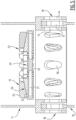
- Figure 10 shows an embodiment wherein the actuator 20 is arranged in a fastening device 37 that comprises a support 38.
- This support 38 may be configured to be supported on an inner one of the walls 17.
- the actuator 20 may be rotatably arranged relative to the support 38 to allow the actuator to successively engage a specific connector 19 or connectors 19.
- the actuator 20 is configured to simultaneously move said connector 19 and at least one or more than one further connector 19 in an axial direction of their associated channels 18.
- two connectors 19, that are arranged opposite relative to each other are actuated simultaneously. In this way, reaction forces may cancel each other out.
- a cancelling out of reaction forces may also be obtained with other configurations, such as with a triangular configuration of three hydraulic cylinders 31 that are oriented at 120° relative to each other.
- a square configuration may comprise four hydraulic cylinders 31 that are oriented at 90 ° relative to each other, etcetera.
- the clamping device 23 is arranged inside the second member 11.
- a correct positioning of the connectors 19 relative to the through holes 13, 14 of the second member is guaranteed. Consequently, the connectors 19 of said clamping device 23 are not only in alignment with the through holes 13, 14 of the second member, but they are also in alignment with the associated channels 18. In this way, the connectors 19 may be easily positioned, also in under water conditions.
- Figure 1 shows an offshore wind turbine tower construction and Figures 3A , 3B , 4-8 show tubular members of a limited diameter as e.g. applied for jackets.
- the first and the second member may be members of an offshore construction, preferably of an offshore wind turbine construction or a jacket construction.
- Each of the first 10 and the second member 11 are preferably tubular members of a monopile or a jacket construction.
- one of the first 10 and the second member 11 may be a rotor blade of a wind turbine, wherein the other of the first 10 and the second member 11 is arranged on a hub, or both the first and second member 10, 11 may be parts of a turbine blade 6. It is however explicitly mentioned that the assembly according to the invention is not limited to offshore use, nor to wind turbine applications alone.
- FIG. 1 shows embodiments wherein the clamping device 23 is arranged inside the second member 11, the skilled person will understand that an axial insertion of the connector 19 into an associated channel 18 may also be performed by a clamping device 23 that is arranged outside the first and/or second members 10, 11.
- a clamping device 23 arranged outside the first and/or second members 10, 11 provides the additional advantage that it may easily be removed afterwards, and possibly re-used for arranging connectors 19 of further assemblies.
- the lower member is denoted as the first member 10, and that the upper member is denoted as the second member 11.
- the skilled person will understand that the lower member could be interpreted as a second member 11 and the upper member could be interpreted as a first member 10 within the scope of the invention.
Landscapes
- Engineering & Computer Science (AREA)
- General Engineering & Computer Science (AREA)
- Mechanical Engineering (AREA)
- Civil Engineering (AREA)
- Structural Engineering (AREA)
- Chemical & Material Sciences (AREA)
- Life Sciences & Earth Sciences (AREA)
- Architecture (AREA)
- Sustainable Development (AREA)
- Sustainable Energy (AREA)
- Combustion & Propulsion (AREA)
- Materials Engineering (AREA)
- Wood Science & Technology (AREA)
- Mutual Connection Of Rods And Tubes (AREA)
- Wind Motors (AREA)
- Hydraulic Turbines (AREA)
Claims (15)
- Anordnung, umfassend:- ein erstes Element (10) und ein zweites Element (11), die rohrförmige Elemente einer Windturbinentragstruktur (2) sind, wobei;- das zweite Element (11) einen gabelförmigen Querschnitt (15) mit einem Hauptkörper (16), der zwischen zwei im Wesentlichen parallelen Wänden (17) arrangiert ist, aufweist, die jede mindestens ein Durchgangsloch (13, 14) umfassen;- das erste Element (10) zwischen den zwei Wänden (17) des zweiten Elements (11), die das Durchgangsloch (13, 14) aufweisen, arrangiert ist;- wobei ein Durchgangsloch (12) des ersten Elements (10) und die Durchgangslöcher (13, 14) des zweiten Elements (11) einen Kanal (18) definieren;- einen Verbinder (19), der in dem Kanal (18) bis zu einer Endposition axial einführbar und anschließend relativ zu dem Kanal (18) radial ausdehnbar ist, um das erste Element (10) und das zweite Element (11) relativ zueinander zu verbinden;gekennzeichnet durch- einen Stellantrieb (20), der konfiguriert ist, um den Verbinder (19) in eine axiale Richtung in dem Kanal (18) zu bewegen, und der ferner konfiguriert ist zum anschließenden;- Einführen des Verbinders (19) in den Kanal (18) von einer ersten Seite,- Bewegen des Verbinders (19) in die axiale Richtung in dem Kanal (18) bis zu der Endposition, und- Inbewegungsetzen des Verbinders (19) von derselben ersten Seite, um den Verbinder (19) relativ zu dem Kanal (18) radial auszudehnen und dadurch das erste Element (10) und das zweite Element (11) relativ zueinander zu verbinden; und- wobei der Verbinder (19), in einem ausgedehnten Zustand davon, das erste Element (10) in eine radiale Richtung relativ zu dem Kanal (18) gegen eine Fläche (27) des Hauptkörpers (16) des zweiten Elements (11) drückt, um einen Klemmkontakt und dadurch eine vorgespannte Verbindung in der radialen Richtung relativ zu dem Kanal (18) zwischen einer Fläche (28) des ersten Elements (10) und der Fläche (27) des Hauptkörpers (16) des zweiten Elements (11) zu definieren.
- Anordnung nach Anspruch 1, ferner umfassend einen Anschlag (21), der konfiguriert ist, um die Endposition des Verbinders (19) relativ zu dem Kanal (18) festzulegen.
- Anordnung nach Anspruch 2, wobei für den Anschlag (21) mindestens eines gilt von:- umfasst ein Anliegen (22), das konfiguriert ist, um an einem des ersten Elements (10) und des zweiten Elements (11) anzuliegen; und- ist durch eine maximale Verlängerung oder Verschiebung des Stellantriebs (20) definiert.
- Anordnung nach einem der vorstehenden Ansprüche, wobei mindestens eines gilt von:- der Verbinder (19) in dem ausgedehnten Zustand davon, drückt gegen Flächen (29) der Durchgangslöcher (13, 14) des zweiten Elements (11), die von dem Hauptkörper (16) davon weg gerichtet sind, um die vorgespannte Verbindung zwischen dem ersten Element (10) und dem zweiten Element (11) zu definieren; und- in dem ausgedehnten Zustand des Verbinders (19), wobei die Verbindung zwischen dem ersten Element (10) und dem zweiten Element (11) vorgespannt ist, das Durchgangsloch (12) des ersten Elements (10) an einem Versatz relativ zu den Durchgangslöchern (13, 14) in dem zweiten Element (11) arrangiert ist.
- Anordnung nach einem der vorstehenden Ansprüche, wobei der Verbinder (19) umfasst:- einen kompaktierten Zustand, wobei der Verbinder (19) eine Größe, die ein freies Einführen in den Kanal (18) und Herausziehen aus diesem ermöglicht, aufweist; und- einen Verbindungszustand, wobei der Verbinder (19) in dem Kanal (18) ausgedehnt ist, um das erste Element (10) und das zweite Element (11) relativ zueinander zu verbinden.
- Anordnung nach einem der vorstehenden Ansprüche, wobei der Verbinder (19) umfasst:- mindestens einen Ausdehnungsblock (24);- mindestens einen Keil (25), der eine geneigte Oberfläche (26), die dem mindestens einen Ausdehnungsblock (24) zugewandt ist, aufweist; und- und wobei der Stellantrieb (20) konfiguriert ist, um den Keil (25) relativ zu dem Ausdehnungsblock (24) zu verschieben.
- Anordnung nach Anspruch 6 in Abhängigkeit von mindestens Anspruch 2, wobei der Anschlag (21) auf dem mindestens einen Ausdehnungsblock (24) arrangiert ist.
- Anordnung nach einem der vorstehenden Ansprüche, umfassend einen oder mehr als einen weiteren Verbinder (19), wobei der Stellantrieb (20) zwischen dem Verbinder (19) und dem einen oder dem mehr als einen weiteren Verbinder (19) arrangiert ist, wobei jeder des Verbinders (19) und des einen oder des mehr als einen weiteren Verbinders (19) in seinen eigenen Kanal (18) eingeführt ist; und- wobei für den Stellantrieb (20) vorzugsweise mindestens eines gilt von:- konfiguriert, um den Verbinder (19) und mindestens einen oder mehr als einen weiteren Verbinder (19) in eine axiale Richtung ihrer zugehörigen Kanäle (18) gleichzeitig zu bewegen; und- arrangiert in einer Klemmvorrichtung (23).
- Anordnung nach einem der vorstehenden Ansprüche, wobei der Stellantrieb (20) einen oder mehr als einen Hydraulikzylinder (31) umfasst und vorzugsweise mehr als einen Hydraulikzylinder (31), der an eine gemeinsame Druckversorgung (32) angeschlossen ist, umfasst, die konfiguriert ist, um die Hydraulikzylinder (31) gleichzeitig zu bewegen.
- Anordnung nach einem der Ansprüche 6 bis 9, wobei der Ausdehnungsblock (24) eine Oberfläche (33), von der mindestens ein Abschnitt eine Kontaktfläche mit dem Keil (25) ist, aufweist, die eine Ausrichtung, die der geneigten Oberfläche (26) des Keils (25) entspricht, aufweist.
- Anordnung nach einem der vorstehenden Ansprüche, wobei das erste Element (10) und das zweite Element (11) sich überlappende rohrförmige Elemente sind und die Durchgangslöcher (12, 13, 14) relativ zu den rohrförmigen Elementen radial ausgerichtet sind, um den Kanal (18), der sich radial erstreckt, zu definieren;- wobei das erste Element (10) und das zweite Element (11) Längsachsen aufweisen, die vorzugsweise mindestens parallel sind und die mehr bevorzugt zusammentreffen.
- Anordnung nach einem der vorstehenden Ansprüche, wobei mindestens eines gilt von:- der Kanal (18) weist einen länglichen Querschnitt, der sich in eine Längsrichtung mindestens eines des ersten Elements (10) und des zweiten Elements (11) erstreckt, auf;- mehrere Kanäle (18) und Verbinder (19) sind entlang eines Umfangs des ersten Elements (10) und des zweiten Elements (11) arrangiert; und- das zweite Element (11) umfasst eine Anordnung des Hauptkörpers (16) und der zwei im Wesentlichen parallelen Wände (17).
- Verfahren zum Anordnen eines ersten Elements (10) und eines zweiten Elements (11), die rohrförmige Elemente einer Windturbinentragstruktur (2) sind und die jedes mindestens ein Durchgangsloch (12, 13, 14) umfassen, wobei das zweite Element (11) einen gabelförmigen Querschnitt (15) mit einem Hauptkörper (16), der zwischen zwei im Wesentlichen parallelen Wänden (17) arrangiert ist, aufweist, die jede mindestens ein Durchgangsloch (13, 14) umfassen, das Verfahren umfassend die Schritte:- Arrangieren des ersten Elements (10) zwischen den zwei Wänden (17) des zweiten Elements (11);- Positionieren der Durchgangslöcher (12, 13, 14) des ersten Elements (10) und des zweiten Elements (11), um einen Kanal (18) zu definieren;- Einführen eines Verbinders (19) in den Kanal (18) bis zu einer Endposition; und- radial Ausdehnen des Verbinders (19) relativ zu dem Kanal (18), um dadurch das erste Element (10) und das zweite Element (11) relativ zueinander zu verbinden,gekennzeichnet durch:- den Schritt des Bewegens des Verbinders (19) in eine axiale Richtung in dem Kanal (18) durch einen Stellantrieb (20) nach dem Schritt des Einführens des Verbinders (19) in den Kanal (18) und vor dem Schritt des radialen Ausdehnens des Verbinders (19) relativ zu dem Kanal (18); und- den Schritt des radialen Ausdehnens des Verbinders (91) relativ zu dem Kanal (18), um dadurch das erste Element (10) und das zweite Element (11) relativ zueinander zu verbinden, umfassend das Drücken des ersten Elements (10) in eine radiale Richtung relativ zu dem Kanal (19) gegen eine Fläche (27) des Hauptkörpers (16) des zweiten Elements (11) durch den ausgedehnten Verbinder (19), um einen Klemmkontakt und dadurch eine vorgespannte Verbindung in einer radialen Richtung relativ zu dem Kanal (18) zwischen einer Fläche (28) des ersten Elements (10) und der Fläche (27) des Hauptkörpers (16) des zweiten Elements (11) zu definieren;
wobei der Schritt des Einführens des Verbinders (19) in den Kanal (18) bis zu der Endposition die Schritte umfasst:
dass der Stellantrieb (20) den Verbinder (19) von einer ersten Seite in den Kanal (18) einführt,- dass der Stellantrieb (20) den Verbinder (19) in die axiale Richtung in dem Kanal (18) von derselben ersten Seite in die Endposition bewegt, und- wobei der Schritt des anschließend radialen Ausdehnens des Verbinders relativ zu dem Kanal vorzugsweise umfasst, dass der Stellantrieb (20) den Verbinder (19) von derselben ersten Seite in Bewegung setzt, wobei dadurch der Verbinder (19) relativ zu dem Kanal (18) radial ausgedehnt wird und das erste Element (10) und das zweite Element (11) relativ zueinander verbunden werden. - Verfahren nach Anspruch 13, ferner umfassend den Schritt des:- Festlegens der Endposition des Verbinders (19) relativ zu dem Kanal (18) durch einen Anschlag (21).
- Verfahren nach Anspruch 14, wobei:- der Schritt des Bewegens des Verbinders (19) in die axiale Richtung in dem Kanal (18) durch den Stellantrieb (20) durchgeführt wird, bis der Verbinder (19) seine Endposition, wie durch den Anschlag (21) definiert, erreicht; und- der Schritt des anschließenden radialen Ausdehnen des Verbinders (19) relativ zu dem Kanal (18) bei weiterer Inbewegungsetzung des Stellantriebs (20) durchgeführt wird, sobald der Verbinder (19) seine Endposition erreicht hat.
Applications Claiming Priority (2)
| Application Number | Priority Date | Filing Date | Title |
|---|---|---|---|
| NL2024795A NL2024795B1 (en) | 2020-01-30 | 2020-01-30 | Assembly comprising a first and a second member and a connector, and a method of assembling such an assembly |
| PCT/NL2021/050058 WO2021154080A1 (en) | 2020-01-30 | 2021-01-29 | Assembly comprising a first and a second member and a connector, and a method of assembling such an assembly |
Publications (3)
| Publication Number | Publication Date |
|---|---|
| EP4097352A1 EP4097352A1 (de) | 2022-12-07 |
| EP4097352B1 true EP4097352B1 (de) | 2025-06-04 |
| EP4097352C0 EP4097352C0 (de) | 2025-06-04 |
Family
ID=70155268
Family Applications (1)
| Application Number | Title | Priority Date | Filing Date |
|---|---|---|---|
| EP21703781.1A Active EP4097352B1 (de) | 2020-01-30 | 2021-01-29 | Anordnung mit einem ersten und einem zweiten element und einem verbinder und verfahren zur montage solch einer anordnung |
Country Status (5)
| Country | Link |
|---|---|
| US (1) | US11846109B2 (de) |
| EP (1) | EP4097352B1 (de) |
| ES (1) | ES3036326T3 (de) |
| NL (1) | NL2024795B1 (de) |
| WO (1) | WO2021154080A1 (de) |
Families Citing this family (2)
| Publication number | Priority date | Publication date | Assignee | Title |
|---|---|---|---|---|
| NL2024795B1 (en) | 2020-01-30 | 2021-09-10 | C1 Connections Holding B V | Assembly comprising a first and a second member and a connector, and a method of assembling such an assembly |
| NL2037266B1 (en) * | 2024-03-15 | 2025-09-26 | C1 Connections Holding B V | Expansion connector, wind turbine assembly, and method |
Citations (1)
| Publication number | Priority date | Publication date | Assignee | Title |
|---|---|---|---|---|
| WO2020035770A1 (en) * | 2018-08-13 | 2020-02-20 | Siemens Gamesa Renewable Energy B.V. | Assembly comprising a first and a second member and a connector, and a method of assembling such an assembly |
Family Cites Families (9)
| Publication number | Priority date | Publication date | Assignee | Title |
|---|---|---|---|---|
| US4684280A (en) * | 1986-04-14 | 1987-08-04 | Pneumo Abex Corporation | Clevis connection |
| US20080080946A1 (en) * | 2006-10-02 | 2008-04-03 | Tracy Livingston | Expansion pin system for a wind turbine structural tower |
| GB2468926B (en) * | 2009-03-27 | 2013-08-07 | Claxton Engineering Services Ltd | Tubular connector |
| GB2484672B (en) * | 2010-10-18 | 2013-10-16 | Claxton Engineering Services Ltd | Tower connector |
| GB201321989D0 (en) * | 2013-12-12 | 2014-01-29 | Claxton Engineering Services Ltd | Connector for joining two tubular members |
| DK3574150T3 (da) | 2017-01-27 | 2020-12-21 | Siemens Gamesa Renewable Energy B V | Samling, der omfatter et første og et andet afsnit og en fiksering |
| CN107742472B (zh) | 2017-09-25 | 2021-03-26 | 昆山国显光电有限公司 | 封装掩膜板、封装方法及显示面板 |
| NL2020968B1 (en) * | 2018-05-22 | 2019-11-28 | Fistuca B V | Assembly comprising a first and a second section and a fixation |
| NL2024795B1 (en) | 2020-01-30 | 2021-09-10 | C1 Connections Holding B V | Assembly comprising a first and a second member and a connector, and a method of assembling such an assembly |
-
2020
- 2020-01-30 NL NL2024795A patent/NL2024795B1/en active
-
2021
- 2021-01-29 WO PCT/NL2021/050058 patent/WO2021154080A1/en not_active Ceased
- 2021-01-29 EP EP21703781.1A patent/EP4097352B1/de active Active
- 2021-01-29 ES ES21703781T patent/ES3036326T3/es active Active
- 2021-01-29 US US17/795,445 patent/US11846109B2/en active Active
Patent Citations (1)
| Publication number | Priority date | Publication date | Assignee | Title |
|---|---|---|---|---|
| WO2020035770A1 (en) * | 2018-08-13 | 2020-02-20 | Siemens Gamesa Renewable Energy B.V. | Assembly comprising a first and a second member and a connector, and a method of assembling such an assembly |
Also Published As
| Publication number | Publication date |
|---|---|
| WO2021154080A1 (en) | 2021-08-05 |
| US20230069473A1 (en) | 2023-03-02 |
| ES3036326T3 (en) | 2025-09-17 |
| EP4097352A1 (de) | 2022-12-07 |
| NL2024795B1 (en) | 2021-09-10 |
| EP4097352C0 (de) | 2025-06-04 |
| US11846109B2 (en) | 2023-12-19 |
Similar Documents
| Publication | Publication Date | Title |
|---|---|---|
| EP3837437B1 (de) | Anordnung mit einem ersten und einem zweiten element und einem verbinder und verfahren zur montage solch einer anordnung | |
| CN110741122B (zh) | 包括第一区段和第二区段以及固定器的组件 | |
| US8578681B2 (en) | Tower connector | |
| EP4097352B1 (de) | Anordnung mit einem ersten und einem zweiten element und einem verbinder und verfahren zur montage solch einer anordnung | |
| EP1625999B1 (de) | Nichtkonzentrische Hochleistungs-Konstruktionsverbinder | |
| EP4413271B1 (de) | Anordnung mit einem ersten und einem zweiten element und einem verbinder sowie verfahren zur montage solch einer anordnung | |
| US20080078083A1 (en) | Drive pin system for a wind turbine structural tower | |
| WO2025191128A1 (en) | Expansion connector, wind turbine assembly, and method | |
| CN121039406A (zh) | 组件及组装组件的方法 |
Legal Events
| Date | Code | Title | Description |
|---|---|---|---|
| STAA | Information on the status of an ep patent application or granted ep patent |
Free format text: STATUS: UNKNOWN |
|
| STAA | Information on the status of an ep patent application or granted ep patent |
Free format text: STATUS: THE INTERNATIONAL PUBLICATION HAS BEEN MADE |
|
| PUAI | Public reference made under article 153(3) epc to a published international application that has entered the european phase |
Free format text: ORIGINAL CODE: 0009012 |
|
| STAA | Information on the status of an ep patent application or granted ep patent |
Free format text: STATUS: REQUEST FOR EXAMINATION WAS MADE |
|
| 17P | Request for examination filed |
Effective date: 20220718 |
|
| AK | Designated contracting states |
Kind code of ref document: A1 Designated state(s): AL AT BE BG CH CY CZ DE DK EE ES FI FR GB GR HR HU IE IS IT LI LT LU LV MC MK MT NL NO PL PT RO RS SE SI SK SM TR |
|
| DAV | Request for validation of the european patent (deleted) | ||
| DAX | Request for extension of the european patent (deleted) | ||
| STAA | Information on the status of an ep patent application or granted ep patent |
Free format text: STATUS: EXAMINATION IS IN PROGRESS |
|
| 17Q | First examination report despatched |
Effective date: 20230712 |
|
| RAP3 | Party data changed (applicant data changed or rights of an application transferred) |
Owner name: C1 CONNECTIONS B.V. |
|
| REG | Reference to a national code |
Ref country code: DE Ref legal event code: R079 Free format text: PREVIOUS MAIN CLASS: F03D0013100000 Ipc: F03D0013200000 Ref document number: 602021031723 Country of ref document: DE |
|
| RIC1 | Information provided on ipc code assigned before grant |
Ipc: E02B 17/02 20060101ALI20250107BHEP Ipc: E02B 17/00 20060101ALI20250107BHEP Ipc: E04H 12/08 20060101ALI20250107BHEP Ipc: F03D 13/10 20160101ALI20250107BHEP Ipc: F03D 13/25 20160101ALI20250107BHEP Ipc: F03D 13/20 20160101AFI20250107BHEP |
|
| GRAP | Despatch of communication of intention to grant a patent |
Free format text: ORIGINAL CODE: EPIDOSNIGR1 |
|
| STAA | Information on the status of an ep patent application or granted ep patent |
Free format text: STATUS: GRANT OF PATENT IS INTENDED |
|
| RAP1 | Party data changed (applicant data changed or rights of an application transferred) |
Owner name: C1 CONNECTIONS HOLDING B.V. |
|
| INTG | Intention to grant announced |
Effective date: 20250220 |
|
| GRAS | Grant fee paid |
Free format text: ORIGINAL CODE: EPIDOSNIGR3 |
|
| GRAA | (expected) grant |
Free format text: ORIGINAL CODE: 0009210 |
|
| STAA | Information on the status of an ep patent application or granted ep patent |
Free format text: STATUS: THE PATENT HAS BEEN GRANTED |
|
| AK | Designated contracting states |
Kind code of ref document: B1 Designated state(s): AL AT BE BG CH CY CZ DE DK EE ES FI FR GB GR HR HU IE IS IT LI LT LU LV MC MK MT NL NO PL PT RO RS SE SI SK SM TR |
|
| REG | Reference to a national code |
Ref country code: GB Ref legal event code: FG4D |
|
| REG | Reference to a national code |
Ref country code: CH Ref legal event code: EP |
|
| REG | Reference to a national code |
Ref country code: DE Ref legal event code: R096 Ref document number: 602021031723 Country of ref document: DE |
|
| REG | Reference to a national code |
Ref country code: IE Ref legal event code: FG4D |
|
| U01 | Request for unitary effect filed |
Effective date: 20250611 |
|
| U07 | Unitary effect registered |
Designated state(s): AT BE BG DE DK EE FI FR IT LT LU LV MT NL PT RO SE SI Effective date: 20250620 |
|
| REG | Reference to a national code |
Ref country code: ES Ref legal event code: FG2A Ref document number: 3036326 Country of ref document: ES Kind code of ref document: T3 Effective date: 20250917 |
|
| PG25 | Lapsed in a contracting state [announced via postgrant information from national office to epo] |
Ref country code: GR Free format text: LAPSE BECAUSE OF FAILURE TO SUBMIT A TRANSLATION OF THE DESCRIPTION OR TO PAY THE FEE WITHIN THE PRESCRIBED TIME-LIMIT Effective date: 20250905 Ref country code: NO Free format text: LAPSE BECAUSE OF FAILURE TO SUBMIT A TRANSLATION OF THE DESCRIPTION OR TO PAY THE FEE WITHIN THE PRESCRIBED TIME-LIMIT Effective date: 20250904 |
|
| PG25 | Lapsed in a contracting state [announced via postgrant information from national office to epo] |
Ref country code: PL Free format text: LAPSE BECAUSE OF FAILURE TO SUBMIT A TRANSLATION OF THE DESCRIPTION OR TO PAY THE FEE WITHIN THE PRESCRIBED TIME-LIMIT Effective date: 20250604 |
|
| PG25 | Lapsed in a contracting state [announced via postgrant information from national office to epo] |
Ref country code: HR Free format text: LAPSE BECAUSE OF FAILURE TO SUBMIT A TRANSLATION OF THE DESCRIPTION OR TO PAY THE FEE WITHIN THE PRESCRIBED TIME-LIMIT Effective date: 20250604 |
|
| PG25 | Lapsed in a contracting state [announced via postgrant information from national office to epo] |
Ref country code: RS Free format text: LAPSE BECAUSE OF FAILURE TO SUBMIT A TRANSLATION OF THE DESCRIPTION OR TO PAY THE FEE WITHIN THE PRESCRIBED TIME-LIMIT Effective date: 20250904 |