EP4096974B1 - Verfahren und vorrichtung zum betreiben einer antiblockiersystem-steuereinheit für ein hochautomatisiertes fahrzeug mit zumindest einer lenkachse - Google Patents
Verfahren und vorrichtung zum betreiben einer antiblockiersystem-steuereinheit für ein hochautomatisiertes fahrzeug mit zumindest einer lenkachse Download PDFInfo
- Publication number
- EP4096974B1 EP4096974B1 EP21701792.0A EP21701792A EP4096974B1 EP 4096974 B1 EP4096974 B1 EP 4096974B1 EP 21701792 A EP21701792 A EP 21701792A EP 4096974 B1 EP4096974 B1 EP 4096974B1
- Authority
- EP
- European Patent Office
- Prior art keywords
- signal
- steering
- vehicle
- steering axle
- axle
- Prior art date
- Legal status (The legal status is an assumption and is not a legal conclusion. Google has not performed a legal analysis and makes no representation as to the accuracy of the status listed.)
- Active
Links
Images
Classifications
-
- B—PERFORMING OPERATIONS; TRANSPORTING
- B60—VEHICLES IN GENERAL
- B60T—VEHICLE BRAKE CONTROL SYSTEMS OR PARTS THEREOF; BRAKE CONTROL SYSTEMS OR PARTS THEREOF, IN GENERAL; ARRANGEMENT OF BRAKING ELEMENTS ON VEHICLES IN GENERAL; PORTABLE DEVICES FOR PREVENTING UNWANTED MOVEMENT OF VEHICLES; VEHICLE MODIFICATIONS TO FACILITATE COOLING OF BRAKES
- B60T7/00—Brake-action initiating means
- B60T7/12—Brake-action initiating means for automatic initiation; for initiation not subject to will of driver or passenger
-
- B—PERFORMING OPERATIONS; TRANSPORTING
- B60—VEHICLES IN GENERAL
- B60T—VEHICLE BRAKE CONTROL SYSTEMS OR PARTS THEREOF; BRAKE CONTROL SYSTEMS OR PARTS THEREOF, IN GENERAL; ARRANGEMENT OF BRAKING ELEMENTS ON VEHICLES IN GENERAL; PORTABLE DEVICES FOR PREVENTING UNWANTED MOVEMENT OF VEHICLES; VEHICLE MODIFICATIONS TO FACILITATE COOLING OF BRAKES
- B60T13/00—Transmitting braking action from initiating means to ultimate brake actuator with power assistance or drive; Brake systems incorporating such transmitting means, e.g. air-pressure brake systems
- B60T13/10—Transmitting braking action from initiating means to ultimate brake actuator with power assistance or drive; Brake systems incorporating such transmitting means, e.g. air-pressure brake systems with fluid assistance, drive, or release
- B60T13/66—Electrical control in fluid-pressure brake systems
- B60T13/662—Electrical control in fluid-pressure brake systems characterised by specified functions of the control system components
-
- B—PERFORMING OPERATIONS; TRANSPORTING
- B60—VEHICLES IN GENERAL
- B60T—VEHICLE BRAKE CONTROL SYSTEMS OR PARTS THEREOF; BRAKE CONTROL SYSTEMS OR PARTS THEREOF, IN GENERAL; ARRANGEMENT OF BRAKING ELEMENTS ON VEHICLES IN GENERAL; PORTABLE DEVICES FOR PREVENTING UNWANTED MOVEMENT OF VEHICLES; VEHICLE MODIFICATIONS TO FACILITATE COOLING OF BRAKES
- B60T8/00—Arrangements for adjusting wheel-braking force to meet varying vehicular or ground-surface conditions, e.g. limiting or varying distribution of braking force
- B60T8/17—Using electrical or electronic regulation means to control braking
- B60T8/1755—Brake regulation specially adapted to control the stability of the vehicle, e.g. taking into account yaw rate or transverse acceleration in a curve
Definitions
- the present invention relates to a method and a device for operating an anti-lock braking system control unit for a highly automated vehicle with at least one steering axle and an anti-lock braking system control unit with a device.
- an electrically controllable steering system of a highly automated vehicle fails, other driving functions of the vehicle can be used as a fallback level in order to continue to ensure steering of the vehicle, for example a steering brake function of the vehicle.
- the object of the invention is an improved method for operating an anti-lock braking system control unit for a highly automated vehicle with at least one steering axle, an improved device for operating an anti-lock braking system control unit for a highly automated vehicle with at least one steering axle and an improved anti-lock braking system control unit to create with a device.
- the EP 2 357 112 A2 describes a method for controlling at least one parking brake device.
- a method for operating an anti-lock braking system control unit for a highly automated vehicle with at least one steering axle has a reading step and a sending step.
- an activation signal is read in, which represents an activated steering brake function of the vehicle and additionally or alternatively a deactivated, electrically controllable steering function of the vehicle.
- a control signal is sent using or in response to the activation signal, which is designed to set a control mode for controlling an ABS function of the anti-lock braking system control unit for at least the steering axle of the vehicle.
- This method can be implemented, for example, in software or hardware or in a mixed form of software and hardware, for example in a control device.
- the vehicle can have one or more steering axles.
- the vehicle can be a commercial vehicle such as a truck or articulated vehicle.
- the vehicle can also have at least one trailer, which can have at least one steering axle.
- the tractor unit and additionally or alternatively the semi-trailer can have at least one steering axle.
- the steering brake function can be a so-called "steer-by-brake” function, which can be used as a fallback level for a failed electrically controllable steering function. With such a "steer-by-brake” function, brake pressure applied to individual wheels of the vehicle can advantageously lead to the vehicle turning.
- a control mode can be set which is designed to harmonize braking torques of the first wheel and the second wheel of the steering axle in order to minimize steering torques generated in this way.
- the control signal can be sent, which is designed to set a control mode of the ABS function for at least the steering axle, in which the wheel of the steering axle or of the vehicle also the lowest level of traction and/or ground friction determines the braking pressure of the steering axle.
- an even and overall lower brake pressure can advantageously be set for the steering axle than when the wheels are braked individually depending on, for example, only the individual grip.
- a steering process therefore takes place harmoniously and a yaw moment on a yaw axis of the vehicle remains low.
- Such a control mode can also be referred to as a so-called “select-low control mode”.
- select-Low control mode only one pressure control valve can advantageously be used per axis. Decisive for the control under ⁇ spiit conditions, i.e. with different surfaces for the right and left wheels of the steering axle, e.g. B. in snow and asphalt, as already mentioned, the wheel with the lower coefficient of friction is always the one.
- the method can further comprise an actuation step in which, in response to the activation signal, a valve common-mode signal is output, which is designed to actuate at least two pneumatic control valves of an anti-lock braking system in a common mode.
- a valve common-mode signal is output, which is designed to actuate at least two pneumatic control valves of an anti-lock braking system in a common mode.
- the pneumatic control valves can be pressure control valves, or “PCV”s (Pressure Control Valve).
- the method has a limiting step in which a limiting signal is output in response to the activation signal, which is designed to limit a maximum pressure build-up gradient for a pneumatic valve on at least the steering axle.
- a limiting signal is output in response to the activation signal, which is designed to limit a maximum pressure build-up gradient for a pneumatic valve on at least the steering axle.
- the limiting signal can be designed to bring about the maximum pressure build-up gradient within a certain period of time of a braking process, for example at the beginning of the braking process.
- the method may further comprise a reducing step in which, in response to the activation signal, a reduction signal is output which is designed to reduce a target slip value for the ABS function on at least the steering axle. This is also how a turning process can take place harmoniously.
- the method can further comprise a setting step in which, in response to the activation signal, a first target slip signal is output, which is designed to set a first target slip value for the first wheel of the steering axle, and a second target slip signal is output, which is designed to to set a second target slip value for the second wheel of the steering axle, which differs from the first target slip value.
- the method may include an outputting step in which, in response to the activation signal and using a steering signal that represents a steering torque on the steering axle, a rear axle signal is output that is designed to adjust a braking force on at least one rear axle of the vehicle.
- the steering torque can be a predetermined steering torque, which, for example, announces impending yaw of the vehicle.
- a rear axle signal can be output that is designed to set a braking force that is mapped to prevent yaw of the vehicle. This enables the braking force on the rear axle to be balanced so that the resulting yaw moment is, for example, just compensated for by the steering torque on the steering axle.
- the activation signal can be used to shorten the braking distance of the vehicle compared to just a set select-low control.
- the presented invention further creates a device which is designed to carry out, control or implement the steps of a variant of a method presented here in corresponding devices. Also through this one Embodiment variant of the invention in the form of a device, the object on which the invention is based can be solved quickly and efficiently.
- the device can have at least one computing unit for processing signals or data, at least one storage unit for storing signals or data, at least one interface to a sensor or an actuator for reading in sensor signals from the sensor or for outputting data or control signals to the Have an actuator and / or at least one communication interface for reading or outputting data that is embedded in a communication protocol.
- the computing unit can be, for example, a signal processor, a microcontroller or the like, whereby the storage unit can be a flash memory, an EPROM or a magnetic storage unit.
- the communication interface can be designed to read or output data wirelessly and/or by wire, wherein a communication interface that can read or output wired data can, for example, read this data electrically or optically from a corresponding data transmission line or output it into a corresponding data transmission line.
- a device can be understood to mean an electrical device that processes sensor signals and, depending on them, outputs control and/or data signals.
- the device can have an interface that can be designed in hardware and/or software.
- the interfaces can, for example, be part of a so-called system ASIC, which contains a wide variety of functions of the device.
- the interfaces are their own integrated circuits or at least partially consist of discrete components.
- the interfaces can be software modules that are present, for example, on a microcontroller alongside other software modules.
- An anti-lock braking system control unit has the device described above and is designed for use in a highly automated vehicle with at least one steering axle.
- the device can be connected to the anti-lock braking system control unit be connected in terms of signaling or implemented in the anti-lock braking system control unit.
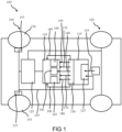
- Fig. 1 shows a schematic representation of a highly automated vehicle 100 with at least one steering axle 105 and an anti-lock braking system control unit 110 and with a device 115 for operating the anti-lock braking system control unit 110 according to an exemplary embodiment. Shown is a view of the vehicle 100 from above.
- the highly automated vehicle 100 is designed as a highly automated commercial vehicle with two axles 105, 120.
- the vehicle 100 according to this exemplary embodiment a rear axle 120.
- the steering axle 105 is the front axle of the vehicle 100.
- the rear axle 120 is also designed as a steerable steering axle 105, or according to an alternative exemplary embodiment, the vehicle 100 has at least one further steerable steering axle 105.
- the vehicle 100 has an anti-lock braking system 125 and the anti-lock braking system control unit 110 for controlling the anti-lock braking system 125.
- the device 115 is designed to operate the anti-lock braking system control unit 110.
- the device 115 according to this exemplary embodiment is accommodated on or in the vehicle 100 purely as an example.
- the device 115 according to this exemplary embodiment is connected to the anti-lock braking system control unit 110 for signaling purposes or is implemented in the anti-lock braking system control unit 110.
- the device 115 has a reading device 127 and a transmitting device 130.
- the reading device 127 is designed to read an activation signal 135, which represents an activated steering brake function of the vehicle 100 and/or a deactivated, electrically controllable steering function of the vehicle 100.
- the transmitting device 130 is designed to send a control signal 140 in response to the activation signal 135, which is designed to set a control mode 145 for controlling an ABS function of the anti-lock braking system control unit 110 for at least the steering axle 105 of the vehicle 100.
- the reading device 127 is designed to read in the activation signal 135, which indicates an activated "steer-by-brake” function as the activated steering brake function, which according to this exemplary embodiment only serves as a fallback level for a failed electrically controllable steering function of the vehicle 100 is activated.
- the transmitting device 130 is designed to set the control mode 145, which is designed to harmonize braking torques of the first wheel 150 and the second wheel 155 of the steering axle 105 to minimize steering torques generated in this way.
- the transmitting device 130 is designed to send the control signal 140, which is designed to set a control mode 145 in which the wheel 150, 155 of the steering axle 105 or the vehicle 100 with the lowest traction has a brake pressure Steering axle 105 determined.
- This control mode 145 can also be referred to as “select-low control mode” 145.
- only one pressure control valve per axis 105, 120 is used in the select low control mode 145.
- the anti-lock braking system control unit 110 includes adjustable additional control modes 160, 165 in the form of an “individual control” 160 and an “individual control modified” 165.
- an optimal brake pressure is individually adjusted for each wheel 150, 155 of the steering axle 105, which causes braking of the respectively assigned wheel 150, 155 via a pneumatic valve 157. This way the shortest braking distances are achieved. However, a large yawing moment occurs at ⁇ -spiit conditions. The vehicle 100 then becomes more difficult to control.
- "Individual control modified" 165 is set, a pressure control valve is used for each wheel 150, 155 of the steering axle 105. A brake pressure difference between the right and left front wheels 150, 155 is limited to a permissible level.
- the transmitting device 130 is designed to further output a valve common mode signal 170, a limitation signal 175, a reduction signal 180, a first target slip signal 185, a second target slip signal 190 and/or a rear axle signal 195 in response to the activation signal 135.
- the valve common mode signal 170 is designed to trigger at least two pneumatic control valves of the anti-lock braking system 125 in a common mode.
- the limitation signal 175 is designed to limit a maximum pressure build-up gradient on at least the steering axle 105.
- the limiting signal 175 is designed to bring about the maximum pressure build-up gradient within a certain period of time of a braking process, according to this exemplary embodiment within a certain period of time from the start of the braking process.
- the reduction signal 180 is designed to reduce a target slip value for the ABS function on at least the steering axle 105.
- the first target slip signal 185 is designed to set a first target slip value for the first wheel 150 of the steering axle 105 and the second target slip signal 190 is designed to set a second target slip value for the second wheel 155 of the steering axle 105, which is different from the first target slip value differs.
- the transmitting device 130 is designed to output the rear axle signal 195 in response to the activation signal 135 and using a steering signal 197, which represents a steering torque on the steering axle 105, which is designed to generate a braking force on at least the rear axle 120 of the vehicle 100 to set.
- a rear axle signal 195 is output, which is designed to set a braking force that is mapped to prevent yaw of the vehicle 100.
- the steering signal 197 represents a predetermined steering torque on the steering axle 105.
- the device 115 is designed to read the activation signal 135 from a driving assistance system of the vehicle 100.
- the device 115 is further designed according to this exemplary embodiment to read the steering signal 197 from a sensor, an evaluation device or the anti-lock braking system control unit 110.
- the device 115 is designed to output the valve common mode signal 170, limitation signal 175, reduction signal 180, first target slip signal 185, second target slip signal 190 and/or rear axle signal 195 to the anti-lock braking system control unit 110 or the anti-lock braking system 125.
- the device 115 presented here advantageously implements an ABS control method for the “steer-by-brake” steering brake function as steering redundancy.
- One task of the device 115 is to provide the “steer-by-brake” steering brake function, for example. B. as a fallback level for electrically controllable steering in highly automated driving, even in the event that the vehicle 100 is braked and even under difficult friction conditions.
- a fundamental advantage of the device 115 is that the brake system - if it takes over the steering function, also known as the "SBB function" for short, in the event of a failure of the electrically controllable steering through steer-by-brake - the ABS controller at least on the steering axle 105 switches to select low control mode 145 (or similar) in order to harmonize the braking torques on the left and right and thus minimize the induced steering torques.
- the SBB function the steering function
- the SBB function in the vehicle 100 shares with one or more steering axles 105 in the form of steered front axles, as soon as it is activated, the ABS function sets the front axle(s) 105 into the select low control mode 145 (or similar).
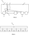
- Fig. 2 shows a schematic side view of a vehicle 100 with a device 115 according to an exemplary embodiment. This can be an exemplary embodiment based on Fig. 1 described vehicle 100 act with the device 115.
- the vehicle 100 is designed as a semi-trailer vehicle with a tractor unit 200 and/or a semi-trailer 205.
- the tractor unit 200 and/or the semi-trailer 205 has at least one or more steering axles 105.
- the device 115 is designed to output control signals 140 to one or more anti-lock braking system control units of the articulated vehicle in order to set the control mode for several or all steering axles 105 of the articulated vehicle.
- the device 115 is accommodated in or on the tractor unit 200. According to an alternative exemplary embodiment, the device 115 is accommodated in or on the semi-trailer 205, or the semi-trailer 205 has a further device 115 corresponding to the device 115.
- Fig. 3 shows a flowchart of a method 300 for operating an anti-lock braking system control unit for a highly automated vehicle with at least one steering axle according to an exemplary embodiment.
- This can be the in Fig. 1 or 2 act as the anti-lock braking system control unit described.
- the procedure 300 is from the in Fig. 1 or 2 Device described can be executed or controlled.
- the method 300 has a step 305 of reading and a step 310 of sending.
- step 305 of reading an activation signal is read in, which represents an activated steering brake function of the vehicle and/or a deactivated, electrically controllable steering function of the vehicle.
- step 310 of sending a control signal is sent in response to the activation signal, which is designed to set a control mode for controlling an ABS function of the anti-lock braking system control unit for at least the steering axle of the vehicle.
- the method 300 has a step 315 of driving, a step 320 of limiting, a step 325 of reducing, a step 330 of setting and/or a step 335 of outputting.
- a valve common-mode signal is output in response to the activation signal, which is designed to activate at least two pneumatic control valves of an anti-lock braking system in a common mode.
- a limiting signal is output in response to the activation signal, which is designed to limit a maximum pressure build-up gradient on at least the steering axle.
- a reduction signal is output in response to the activation signal, which is designed to reduce a target slip value for the ABS function on at least the steering axle.
- step 330 of setting in response to the activation signal, a first target slip signal is output, which is designed to set a first target slip value for the first wheel of the steering axle, and a second target slip signal is output, which is designed to be used for the second wheel of the Steering axis to set a second target slip value that differs from the first target slip value.
- step 335 of outputting in response to the activation signal and using a steering signal that represents a steering torque on the steering axle, a rear axle signal is output that is designed to adjust a braking force on at least one rear axle of the vehicle.
- an exemplary embodiment includes an "and/or" link between a first feature and a second feature, this should be read as meaning that the exemplary embodiment has both the first feature and the second feature according to one embodiment and either only that according to a further embodiment first feature or only the second feature.
Landscapes
- Engineering & Computer Science (AREA)
- Transportation (AREA)
- Mechanical Engineering (AREA)
- Regulating Braking Force (AREA)
Description
- Die Vorliegende Erfindung bezieht sich auf ein Verfahren und eine Vorrichtung zum Betreiben einer Antiblockiersystem-Steuereinheit für ein hochautomatisiertes Fahrzeug mit zumindest einer Lenkachse und eine Antiblockiersystem-Steuereinheit mit einer Vorrichtung.
- Bei einem Ausfall einer elektrisch ansteuerbaren Lenkung eines hochautomatisierten Fahrzeugs können als Rückfallebene andere Fahrfunktionen des Fahrzeugs zum Einsatz kommen, um eine Lenkung des Fahrzeugs weiterhin sicherzustellen, beispielsweise eine Lenkbremsfunktion des Fahrzeugs.
- Vor diesem Hintergrund ist es die Aufgabe der Erfindung ein verbessertes Verfahren zum Betreiben einer Antiblockiersystem-Steuereinheit für ein hochautomatisiertes Fahrzeug mit zumindest einer Lenkachse, eine verbesserte Vorrichtung zum Betreiben einer Antiblockiersystem-Steuereinheit für ein hochautomatisiertes Fahrzeug mit zumindest einer Lenkachse und eine verbesserte Antiblockiersystem-Steuereinheit mit einer Vorrichtung zu schaffen. Die
EP 2 357 112 A2 beschreibt ein Verfahren zum Ansteuern zumindest einer Parkbremseinrichtung. - Diese Aufgabe wird durch ein Verfahren zum Betreiben einer Antiblockiersystem-Steuereinheit für ein hochautomatisiertes Fahrzeug mit zumindest einer Lenkachse mit den Merkmalen des Verfahrensanspruchs 1, durch eine Vorrichtung nach Anspruch 8, durch eine Antiblockiersystem-Steuereinheit nach Anspruch 9 und durch ein Computerprogramm nach Anspruch 10 gelöst. ,
- Die mit der vorgestellten Erfindung erreichbaren Vorteile bestehen darin, dass bei einem Ausfall einer elektrisch ansteuerbaren Lenkung eines hochautomatisierten Fahrzeugs ein Rückfall auf eine Lenkbremsfunktion ermöglicht wird, bei der ein harmonischer Lenkwinkel für eine Lenkachse einstellt wird.
- Ein Verfahren zum Betreiben einer Antiblockiersystem-Steuereinheit für ein hochautomatisiertes Fahrzeug mit zumindest einer Lenkachse weist einen Schritt des Einlesens und einen Schritt des Sendens auf. Im Schritt des Einlesens wird ein Aktivierungssignal eingelesen, das eine aktivierte Lenkbremsfunktion des Fahrzeugs und zusätzlich oder alternativ eine deaktivierte elektrisch ansteuerbare Lenkfunktion des Fahrzeugs repräsentiert. Im Schritt des Sendens wird unter Verwendung oder ansprechend auf das Aktivierungssignal ein Regelsignal gesendet, das dazu ausgebildet ist, um einen Regelmodus zum Regeln einer ABS-Funktion der Antiblockiersystem-Steuereinheit für zumindest die Lenkachse des Fahrzeugs einzustellen.
- Dieses Verfahren kann beispielsweise in Software oder Hardware oder in einer Mischform aus Software und Hardware beispielsweise in einem Steuergerät implementiert sein.
- Das Fahrzeug kann eine oder mehrere Lenkachsen aufweisen. Beispielsweise kann das Fahrzeug ein Nutzfahrzeug wie ein Lastkraftwagen oder Sattelkraftfahrzeug sein. Das Fahrzeug kann ferner zumindest einen Trailer (Anhänger) aufweisen, welcher zumindest eine Lenkachse aufweisen kann. Im Falle eines Sattelkraftfahrzeugs können die Sattelzugmaschine und zusätzlich oder alternativ der Sattelauflieger zumindest eine Lenkachse aufweisen. Bei der Lenkbremsfunktion kann es sich um eine sogenannte "Steer-by-brake"-Funktion handeln, welche als Rückfallebene für eine ausgefallene elektrisch ansteuerbare Lenkfunktion eingesetzt werden kann. Bei einer solchen "Steer-by-brake"-Funktion kann vorteilhafterweise ein auf einzelne Räder des Fahrzeugs bewirkter Bremsdruck zu einem Einlenken des Fahrzeugs führen. Vorteilhafterweise kann im Schritt des Sendens ein Regelmodus eingestellt werden, der dazu ausgebildet ist, um Bremsmomente des ersten Rads und des zweiten Rads der Lenkachse zu harmonisieren, um so erzeugte Lenkmomente zu minimieren.
- Beispielsweise kann im Schritt des Senden das Regelsignal gesendet werden, das dazu ausgebildet ist, um einen Regelmodus der ABS-Funktion für zumindest die Lenkachse einzustellen, bei dem dasjenige Rad der Lenkachse oder des Fahrzeugs mit einer geringsten Bodenhaftung und/oder Bodenreibung einen Bremsdruck der Lenkachse bestimmt.
- Wenn das Rad mit dem geringsten Reibwert als Referenz zum Einstellen des Bremsdrucks genutzt wird, kann vorteilhafterweise ein gleichmäßiger und insgesamt geringerer Bremsdruck für die Lenkachse eingestellt werden, als bei einem individuellen Bremsen der Räder abhängig von beispielsweise lediglich der individuellen Bodenhaftung. Ein Einlenkvorgang erfolgt somit harmonisch und ein Giermoment auf eine Gierachse des Fahrzeugs bleibt gering. Ein solcher Regelmodus kann auch als sogenannter "Select-Low-Regelmodus" bezeichnet werden. Im "Select-Low-Regelmodus" kann vorteilhafterweise nur ein Drucksteuerventil pro Achse zum Einsatz kommen. Ausschlaggebend für die Ansteuerung bei µ-Spiit-Bedingungen, also bei unterschiedlichem Belag für das rechte und linke Rad der Lenkachse, z. B. bei Schnee und Asphalt, ist hierbei wie bereits erwähnt immer das Rad mit dem niedrigeren Reibwert.
- Das Verfahren kann ferner einen Schritt des Ansteuerns aufweisen, in dem ansprechend auf das Aktivierungssignal ein Ventilgleichtaktsignal ausgegeben wird, das dazu ausgebildet ist, um eine Ansteuerung von zumindest zwei pneumatischen Regelventilen eines Antiblockiersystems in einem Gleichtakt zu bewirken. So kann sichergestellt werden, dass die resultierenden Bremsdrücke tatsächlich gleich verlaufen und ein Einlenken somit, beispielsweise an einer oder mehreren Lenkachsen des Fahrzeugs, harmonisch verläuft. Bei den pneumatischen Regelventilen kann es sich um Druckregelventile, kurz "PCV"s (Pressure Control Valve) handeln.
- Es ist weiterhin von Vorteil, wenn das Verfahren einen Schritt des Begrenzens aufweist, in dem ansprechend auf das Aktivierungssignal ein Begrenzungssignal ausgegeben wird, das dazu ausgebildet ist, um einen maximalen Druckaufbaugradienten für ein pneunatisches Ventil an zumindest der Lenkachse zu begrenzen. Dies ermöglicht einen gleichzeitigen und somit harmonischen Aufbau von Bremsdruck an beiden Rädern der Lenkachse. Hierbei kann das Begrenzungssignal dazu ausgebildet sein, um den maximalen Druckaufbaugradienten innerhalb einer bestimmten Zeitspanne eines Bremsvorgangs zu bewirken, beispielsweise am Anfang des Bremsvorgangs.
- Gemäß einer Ausführungsform kann das Verfahren ferner einen Schritt des Verringerns aufweisen, in dem ansprechend auf das Aktivierungssignal ein Verringerungssignal ausgegeben wird, das dazu ausgebildet ist, um einen Zielschlupfwert für die ABS-Funktion an zumindest der Lenkachse zu verringern. Auch so kann ein Einlenkvorgang harmonisch erfolgen.
- Das Verfahren kann weiterhin einen Schritt des Einstellens aufweisen, in dem ansprechend auf das Aktivierungssignal ein erstes Zielschlupfsignal ausgegeben wird, das dazu ausgebildet ist, um für das erste Rad der Lenkachse einen ersten Zielschlupfwert einzustellen und ein zweites Zielschlupfsignal ausgegeben wird, das dazu ausgebildet ist, um für das zweite Rad der Lenkachse einen zweiten Zielschlupfwert einzustellen, der sich von dem ersten Zielschlupfwert unterscheidet. Dies erlaubt ein bewusstes Induzieren eines Lenkmoments.
- Das Verfahren kann einen Schritt des Ausgebens aufweisen, in dem ansprechend auf das Aktivierungssignal und unter Verwendung eines Lenksignals, das ein Lenkmoment an der Lenkachse repräsentiert, ein Hinterachssignal ausgegeben wird, das dazu ausgebildet ist, um eine Bremskraft an zumindest einer Hinterachse des Fahrzeugs einzustellen. Das Lenkmoment kann ein vorbestimmtes Lenkmoment sein, das beispielsweise ein bevorstehendes Gieren des Fahrzeugs ankündigt. Hierbei kann ein Hinterachssignal ausgegeben werden, das dazu ausgebildet ist, um eine Bremskraft einzustellen, die dazu abgebildet ist, um ein Gieren des Fahrzeugs zu verhindern. Dies ermöglicht ein Balancieren der Bremskraft an der Hinterachse, dass das entstehende Giermoment beispielsweise gerade noch so durch das Lenkmoment an der Lenkachse kompensiert wird. Vorteilhafterweise kann durch das Aktivierungssignal ein Bremswegs des Fahrzeugs gegenüber lediglich einer eingestellten Select-Low-Regelung verkürzt werden.
- Die vorgestellte Erfindung schafft ferner eine Vorrichtung, die ausgebildet ist, um die Schritte einer Variante eines hier vorgestellten Verfahrens in entsprechenden Einrichtungen durchzuführen, anzusteuern bzw. umzusetzen. Auch durch diese Ausführungsvariante der Erfindung in Form einer Vorrichtung kann die der Erfindung zugrunde liegende Aufgabe schnell und effizient gelöst werden.
- Hierzu kann die Vorrichtung zumindest eine Recheneinheit zum Verarbeiten von Signalen oder Daten, zumindest eine Speichereinheit zum Speichern von Signalen oder Daten, zumindest eine Schnittstelle zu einem Sensor oder einem Aktor zum Einlesen von Sensorsignalen von dem Sensor oder zum Ausgeben von Daten- oder Steuersignalen an den Aktor und/oder zumindest eine Kommunikationsschnittstelle zum Einlesen oder Ausgeben von Daten aufweisen, die in ein Kommunikationsprotokoll eingebettet sind. Die Recheneinheit kann beispielsweise ein Signalprozessor, ein Mikrocontroller oder dergleichen sein, wobei die Speichereinheit ein Flash-Speicher, ein EPROM oder eine magnetische Speichereinheit sein kann. Die Kommunikationsschnittstelle kann ausgebildet sein, um Daten drahtlos und/oder leitungsgebunden einzulesen oder auszugeben, wobei eine Kommunikationsschnittstelle, die leitungsgebundene Daten einlesen oder ausgeben kann, diese Daten beispielsweise elektrisch oder optisch aus einer entsprechenden Datenübertragungsleitung einlesen oder in eine entsprechende Datenübertragungsleitung ausgeben kann.
- Unter einer Vorrichtung kann vorliegend ein elektrisches Gerät verstanden werden, das Sensorsignale verarbeitet und in Abhängigkeit davon Steuer- und/oder Datensignale ausgibt. Die Vorrichtung kann eine Schnittstelle aufweisen, die hard- und/oder softwaremäßig ausgebildet sein kann. Bei einer hardwaremäßigen Ausbildung können die Schnittstellen beispielsweise Teil eines sogenannten System-ASICs sein, der verschiedenste Funktionen der Vorrichtung beinhaltet. Es ist jedoch auch möglich, dass die Schnittstellen eigene, integrierte Schaltkreise sind oder zumindest teilweise aus diskreten Bauelementen bestehen. Bei einer softwaremäßigen Ausbildung können die Schnittstellen Softwaremodule sein, die beispielsweise auf einem Mikrocontroller neben anderen Softwaremodulen vorhanden sind.
- Eine Antiblockiersystem-Steuereinheit weist die vorangehend beschriebene Vorrichtung auf und ist zur Verwendung für ein hochautomatisiertes Fahrzeug mit zumindest einer Lenkachse ausgebildet. Die Vorrichtung kann mit der Antiblockiersystem-Steuereinheit signaltechnisch verbunden oder in die Antiblockiersystem-Steuereinheit implementiert sein.
- Ausführungsbeispiele der hier vorgestellten Erfindung werden in der nachfolgenden Beschreibung mit Bezug zu den Figuren näher erläutert. Es zeigen:
-
Fig. 1 eine schematische Darstellung eines hochautomatisierten Fahrzeugs mit zumindest einer Lenkachse und einer Antiblockiersystem-Steuereinheit und mit einer Vorrichtung zum Betreiben der Antiblockiersystem-Steuereinheit gemäß einem Ausführungsbeispiel; und -
Fig. 2 eine schematische seitliche Darstellung eines Fahrzeugs mit einer Vorrichtung gemäß einem Ausführungsbeispiel; und -
Fig. 3 ein Ablaufdiagramm eines Verfahrens zum Betreiben einer Antiblockiersystem-Steuereinheit für ein hochautomatisiertes Fahrzeug mit zumindest einer Lenkachse gemäß einem Ausführungsbeispiel. - In der nachfolgenden Beschreibung günstiger Ausführungsbeispiele der vorliegenden Erfindung werden für die in den verschiedenen Figuren dargestellten und ähnlich wirkenden Elemente gleiche oder ähnliche Bezugszeichen verwendet, wobei auf eine wiederholte Beschreibung dieser Elemente verzichtet wird.
-
Fig. 1 zeigt eine schematische Darstellung eines hochautomatisierten Fahrzeugs 100 mit zumindest einer Lenkachse 105 und einer Antiblockiersystem-Steuereinheit 110 und mit einer Vorrichtung 115 zum Betreiben der Antiblockiersystem-Steuereinheit 110 gemäß einem Ausführungsbeispiel. Gezeigt ist eine Ansicht des Fahrzeugs 100 von oben. - Das hochautomatisierte Fahrzeug 100 ist gemäß diesem Ausführungsbeispiel als ein hochautomatisiertes Nutzfahrzeug mit zwei Achsen 105, 120 ausgeformt. Außer der lenkbaren Lenkachse 105 weist das Fahrzeug 100 gemäß diesem Ausführungsbeispiel eine Hinterachse 120 auf. Die Lenkachse 105 ist gemäß diesem Ausführungsbeispiel die Vorderachse des Fahrzeugs 100. Gemäß einem Ausführungsbeispiel ist auch die Hinterachse 120 als eine lenkbare Lenkachse 105 ausgebildet, oder das Fahrzeug 100 weist gemäß einem alternativen Ausführungsbeispiel zumindest eine weitere lenkbare Lenkachse 105 auf.
- Das Fahrzeug 100 weist gemäß diesem Ausführungsbeispiel ein Antiblockiersystem 125 und die Antiblockiersystem-Steuereinheit 110 zum Steuern des Antiblockiersystems 125 auf. Die Vorrichtung 115 ist dazu ausgebildet, um die Antiblockiersystem-Steuereinheit 110 zu betreiben. Lediglich beispielhaft ist die Vorrichtung 115 gemäß diesem Ausführungsbeispiel an oder in dem Fahrzeug 100 aufgenommen. Hierbei ist die Vorrichtung 115 gemäß diesem Ausführungsbeispiel mit der Antiblockiersystem-Steuereinheit 110 signaltechnisch verbunden oder in die Antiblockiersystem-Steuereinheit 110 implementiert.
- Die Vorrichtung 115 weist eine Einleseeinrichtung 127 und eine Sendeeinrichtung 130 auf. Die Einleseeinrichtung 127 ist dazu ausgebildet, um eine Aktivierungssignal 135 einzulesen, das eine aktivierte Lenkbremsfunktion des Fahrzeugs 100 und/oder eine deaktivierte elektrisch ansteuerbare Lenkfunktion des Fahrzeugs 100 repräsentiert. Die Sendeeinrichtung 130 ist dazu ausgebildet, um ansprechend auf das Aktivierungssignal 135 ein Regelsignal 140 zu senden, das dazu ausgebildet ist, um einen Regelmodus 145 zum Regeln einer ABS-Funktion der Antiblockiersystem-Steuereinheit 110 für zumindest die Lenkachse 105 des Fahrzeugs 100 einzustellen.
- Gemäß diesem Ausführungsbeispiel ist die Einleseeinrichtung 127 dazu ausgebildet, um das Aktivierungssignal 135 einzulesen, das als die aktivierte Lenkbremsfunktion eine aktivierte "Steer-by-brake"-Funktion anzeigt, welche gemäß diesem Ausführungsbeispiel lediglich als Rückfallebene für eine ausgefallene elektrisch ansteuerbare Lenkfunktion des Fahrzeugs 100 aktiviert wird.
- Gemäß diesem Ausführungsbeispiel ist die Sendeeinrichtung 130 dazu ausgebildet, um den Regelmodus 145 einzustellen, der dazu ausgebildet ist, um Bremsmomente des ersten Rads 150 und des zweiten Rads 155 der Lenkachse 105 zu harmonisieren, um so erzeugte Lenkmomente zu minimieren. Hierzu ist die Sendeeinrichtung 130 gemäß diesem Ausführungsbeispiel dazu ausgebildet, um das Regelsignal 140 zu senden, das dazu ausgebildet ist, um einen Regelmodus 145 einzustellen, bei dem das Rad 150, 155 der Lenkachse 105 oder des Fahrzeugs 100 mit einer geringsten Bodenhaftung einen Bremsdruck der Lenkachse 105 bestimmt. Dieser Regelmodus 145 kann auch als "Select-Low-Regelmodus" 145 bezeichnet werden. Gemäß diesem Ausführungsbeispiel kommt im Select-Low-Regelmodus 145 nur ein Drucksteuerventil pro Achse 105, 120 zum Einsatz. Gemäß diesem Ausführungsbeispiel umfasst die Antiblockiersystem-Steuereinheit 110 einstellbare weitere Regelmodi 160, 165 in Form einer "Individualregelung" 160 und einer "Individualregelung modifiziert" 165.
- Bei eingestellter Individualregelung 160 wird für jedes Rad 150, 155 der Lenkachse 105 individuell ein optimaler Bremsdruck eingeregelt, der überje ein pneumatisches Ventil 157 eine Bremsung des jeweils zugeordneten Rads 150, 155 bewirkt. So werden die kürzesten Bremswege erreicht. Bei µ-Spiit-Bedingungen entsteht jedoch ein großes Giermoment. Das Fahrzeug 100 wird dann schwerer beherrschbar. Bei eingestellter "Individualregelung modifiziert" 165 kommt für jedes Rad 150, 155 der Lenkachse 105 ein Drucksteuerventil zum Einsatz. Ein Bremsdruckunterschied zwischen rechtem und linkem Vorderrad 150, 155 wird hierbei auf ein zulässiges Maß begrenzt. Es ergibt sich ein etwas längerer Bremsweg als bei der Individualregelung 160, das Giermoment wird jedoch reduziert und das Fahrzeug 100 bleibt auch bei kritischen Bremsmanövern beherrschbar. Diese beiden weiteren Regelmodi 160, 165 werden jedoch bei Anliegen des Aktivierungssignals 135 nicht eingestellt.
- Gemäß diesem Ausführungsbeispiel ist die Sendeeinrichtung 130 dazu ausgebildet, um ansprechend auf das Aktivierungssignal 135 ferner ein Ventilgleichtaktsignal 170, ein Begrenzungssignal 175, ein Verringerungssignal 180, ein erstes Zielschlupfsignal 185, ein zweites Zielschlupfsignal 190 und/oder ein Hinterachssignal 195 auszugeben.
- Das Ventilgleichtaktsignal 170 ist dazu ausgebildet, um eine Ansteuerung von zumindest zwei pneumatischen Regelventilen des Antiblockiersystems 125 in einem Gleichtakt zu bewirken. Das Begrenzungssignal 175 ist dazu ausgebildet, um einen maximalen Druckaufbaugradienten an zumindest der Lenkachse 105 zu begrenzen.
- Gemäß einem Ausführungsbeispiel ist das Begrenzungssignal 175 dazu ausgebildet, um den maximalen Druckaufbaugradienten innerhalb einer bestimmten Zeitspanne eines Bremsvorgangs zu bewirken, gemäß diesem Ausführungsbeispiel innerhalb einer bestimmten Zeitspanne ab Beginn des Bremsvorgangs.
- Das Verringerungssignal 180 ist dazu ausgebildet, um einen Zielschlupfwert für die ABS-Funktion an zumindest der Lenkachse 105 zu verringern. Das erste Zielschlupfsignal 185 ist dazu ausgebildet, um für das erste Rad 150 der Lenkachse 105 einen ersten Zielschlupfwert einzustellen und das zweite Zielschlupfsignal 190 ist dazu ausgebildet, um für das zweite Rad 155 der Lenkachse 105 einen zweiten Zielschlupfwert einzustellen, der sich von dem ersten Zielschlupfwert unterscheidet.
- Die Sendeeinrichtung 130 ist dazu ausgebildet, um ansprechend auf das Aktivierungssignal 135 und unter Verwendung eines Lenksignals 197, das ein Lenkmoment an der Lenkachse 105 repräsentiert, das Hinterachssignal 195 auszugeben, das dazu ausgebildet ist, um eine Bremskraft an zumindest der Hinterachse 120 des Fahrzeugs 100 einzustellen. Hierbei wird gemäß einem Ausführungsbeispiel ein Hinterachssignal 195 ausgegeben, das dazu ausgebildet ist, um eine Bremskraft einzustellen, die dazu abgebildet ist, um ein Gieren des Fahrzeugs 100 zu verhindern. Das Lenksignal 197 repräsentiert gemäß diesem Ausführungsbeispiel ein vorbestimmtes Lenkmoment an der Lenkachse 105. Gemäß diesem Ausführungsbeispiel ist die Vorrichtung 115 dazu ausgebildet, um das Aktivierungssignal 135 von einem Fahrassistenzsystem des Fahrzeugs 100 einzulesen. Die Vorrichtung 115 ist ferner gemäß diesem Ausführungsbeispiel dazu ausgebildet, um das Lenksignal 197 von einem Sensor, einer Auswerteeinrichtung oder der Antiblockiersystem-Steuereinheit 110 einzulesen. Die Vorrichtung 115 ist dazu ausgebildet, um das Ventilgleichtaktsignal 170, Begrenzungssignal 175, Verringerungssignal 180, erste Zielschlupfsignal 185, zweite Zielschlupfsignal 190 und/oder Hinterachssignal 195 an die Antiblockiersystem-Steuereinheit 110 oder das Antiblockiersystem 125 auszugeben.
- Die hier vorgestellte Vorrichtung 115 realisiert vorteilhafterweise ein ABS-Regelverfahren für die Lenkbremsfunktion "Steer-By-Brake" als Lenkungsredundanz.
- Eine Aufgabe der Vorrichtung 115 ist es, die Lenkbremsfunktion "Steer-by-brake" z. B. als Rückfallebene für eine elektrisch ansteuerbare Lenkung beim hochautomatisierten Fahren möglichst optimal darzustellen, auch im Falle, dass das Fahrzeug 100 gebremst wird und sogar unter schwierigen Reibverhältnissen.
- Anders als bei dem hier vorgestellten Verfahren unter Verwendung der Vorrichtung 115 entsteht beim Bremsen einzelner Räder 150, 155 als Redundanzebene für die Querführung der physikalische Effekt, dass das Bremsen eines einzelnen Vorderrades 150, 155 ein Lenkmoment erzeugt, was in Verbindung mit einem positiven Lenkrollradius zu einem Einlenken der Räder 150, 155 führt. Das funktioniert auch, wenn beide Räder 150, 155 bereits gebremst werden, indem ein entsprechender Differenzdruck zwischen linkem und rechtem Rad 150, 155 aufgebaut wird, der denselben Effekt bewirkt wie das einseitige Bremsen. Leider ergibt sich ein solcher Lenkeffekt auch dann, wenn die Räder 150, 155 bei einer Bremsung auf links und rechts unterschiedlichen Reibwerten, auch « µ-Split » genannt, durch ABS verschieden stark gebremst werden und zwar sowohl bei Geradeausfahrt als auch bei Kurvenfahrt. Dies ist das normale Regelverhalten von ABS, wenn beide Räder 150, 155 einem eigenen Regelkanal zugeordnet sind, z. B. bei der Individualregelung oder Individualregelung modifiziert.
- Ein grundsätzlicher Vorteil der Vorrichtung 115 besteht nun darin, dass das Bremssystem - wenn es bei Ausfall der elektrisch ansteuerbaren Lenkung durch Steer-By-Brake die Lenkfunktion, auch kurz "SBB-Funktion" genannt, übernimmt - den ABS-Regler mindestens an der Lenkachse 105 in den Select-Low-Regelmodus 145 (oder ähnliches) schaltet, um die Bremsmomente links und rechts zu harmonisieren und damit die induzierten Lenkmomente zu minimieren. Dadurch wird beispielsweise beim Bremsen auf unterschiedlichen Reibwerten der Aufbau eines Lenkmoments vermieden oder zumindest stark abgedämpft, so dass die SBB-Funktion das Fahrzeug 100 weiterhin steuern kann.
- Gemäß diesem Ausführungsbeispiel teilt die SBB-Funktion in dem Fahrzeug 100 mit einer oder auch mehreren Lenkachsen 105 in Form von gelenkten Vorderachsen, sobald sie aktiviert wird, der ABS-Funktion mit, die Vorderachse(n) 105 in den Select-Low-Regelmodus 145 (oder gleichartigen) zu setzen.
- Zusätzliche Optionen sind einzeln oder in beliebiger Kombination:
- Ansteuerung der pneumatischen Regelventile für ABS, z. B. PCVs, im Gleichtakt, damit die resultierenden Bremsdrücke tatsächlich gleich verlaufen.
- Begrenzen des Druckaufbaugradienten am Anfang einer Bremsung, gemäß diesem Ausführungsbeispiel insbesondere an der oder den Lenkachsen 105 und/oder der Hinterachse 120 oder einer anderen ungelenkten Achse, um auch hier keine großen Lenkmomente entstehen zu lassen.
- Verringerung des Zielschlupfwertes für die ABS-Regelung an der Lenkachse 105, um mögliche Lenkmomente z. B. durch unterschiedliches Bremsverhalten links/rechts bedingt, weiter zu verringern und leichter ein Lenkmoment durch Erhöhen des Zielschlupfwertes an einer Achse aufbringen zu können.
- Bewusstes Induzieren eines Lenkmomentes durch unterschiedliche Zielschlupfwerte rechts und links, um das Fahrzeug 100 lateral zu Steuern.
- Balancieren der Bremskraft an der Hinterachse 120 so, dass das entstehende Giermoment gerade noch durch das Lenkmoment an der Lenkachse 105 kompensiert werden kann. Dadurch kann der Bremsweg gegenüber einer reinen Select-Low-Regelung reduziert werden.
-
Fig. 2 zeigt eine schematische seitliche Darstellung eines Fahrzeugs 100 mit einer Vorrichtung 115 gemäß einem Ausführungsbeispiel. Dabei kann es sich um ein Ausführungsbeispiel des anhand vonFig. 1 beschriebenen Fahrzeugs 100 mit der Vorrichtung 115 handeln. - Das Fahrzeug 100 ist gemäß diesem Ausführungsbeispiel als ein Sattelkraftfahrzeug mit einer Sattelzugmaschine 200 und/oder einem Sattelauflieger 205 ausgeformt.
- Gemäß diesem Ausführungsbeispiel weist die Sattelzugmaschine 200 und/oder der Sattelauflieger 205 zumindest eine oder mehrere Lenkachsen 105 auf. Die Vorrichtung 115 ist gemäß diesem Ausführungsbeispiel dazu ausgebildet, um Regelsignale 140 an eine oder mehrere Antiblockiersystem-Steuereinheiten des Sattelkraftfahrzeugs auszugeben, um den Regelmodus für mehrere oder alle Lenkachsen 105 des Sattelkraftfahrzeug einzustellen.
- Die Vorrichtung 115 ist gemäß diesem Ausführungsbeispiel in oder an der Sattelzugmaschine 200 aufgenommen. Gemäß einem alternativen Ausführungsbeispiel ist die Vorrichtung 115 in oder an dem Sattelauflieger 205 aufgenommen, oder der Sattelauflieger 205 weist eine der Vorrichtung 115 entsprechende weitere Vorrichtung 115 auf.
-
Fig. 3 zeigt ein Ablaufdiagramm eines Verfahrens 300 zum Betreiben einer Antiblockiersystem-Steuereinheit für ein hochautomatisiertes Fahrzeug mit zumindest einer Lenkachse gemäß einem Ausführungsbeispiel. Dabei kann es sich um die inFig. 1 oder2 beschriebene Antiblockiersystem-Steuereinheit handeln. Das Verfahren 300 ist von der inFig. 1 oder2 beschriebenen Vorrichtung ausführbar oder ansteuerbar. - Das Verfahren 300 weist einen Schritt 305 des Einlesens und einen Schritt 310 des Sendens auf. Im Schritt 305 des Einlesens wird ein Aktivierungssignal eingelesen, das eine aktivierte Lenkbremsfunktion des Fahrzeugs und/oder eine deaktivierte elektrisch ansteuerbare Lenkfunktion des Fahrzeugs repräsentiert. Im Schritt 310 des Sendens wird ansprechend auf das Aktivierungssignal ein Regelsignal gesendet, das dazu ausgebildet ist, um einen Regelmodus zum Regeln einer ABS-Funktion der Antiblockiersystem-Steuereinheit für zumindest die Lenkachse des Fahrzeugs einzustellen.
- Optional weist das Verfahren 300 gemäß diesem Ausführungsbeispiel einen Schritt 315 des Ansteuerns, einen Schritt 320 des Begrenzens, einen Schritt 325 des Verringerns, einen Schritt 330 des Einstellens und/oder einen Schritt 335 des Ausgebens auf.
- Im Schritt 315 des Ansteuerns wird ansprechend auf das Aktivierungssignal ein Ventilgleichtaktsignal ausgegeben, das dazu ausgebildet ist, um eine Ansteuerung von zumindest zwei pneumatischen Regelventilen eines Antiblockiersystems in einem Gleichtakt zu bewirken. Im Schritt 320 des Begrenzens wird ansprechend auf das Aktivierungssignal ein Begrenzungssignal ausgegeben, das dazu ausgebildet ist, um einen maximalen Druckaufbaugradienten an zumindest der Lenkachse zu begrenzen. Im Schritt 325 des Verringerns wird ansprechend auf das Aktivierungssignal ein Verringerungssignal ausgegeben, das dazu ausgebildet ist, um einen Zielschlupfwert für die ABS-Funktion an zumindest der Lenkachse zu verringern. Im Schritt 330 des Einstellens werden ansprechend auf das Aktivierungssignal ein erstes Zielschlupfsignal ausgegeben, das dazu ausgebildet ist, um für das erste Rad der Lenkachse einen ersten Zielschlupfwert einzustellen und es wird ein zweites Zielschlupfsignal ausgegeben, das dazu ausgebildet ist, um für das zweite Rad der Lenkachse einen zweiten Zielschlupfwert einzustellen, der sich von dem ersten Zielschlupfwert unterscheidet. Im Schritt 335 des Ausgebens wird ansprechend auf das Aktivierungssignal und unter Verwendung eines Lenksignals, das ein Lenkmoment an der Lenkachse repräsentiert, ein Hinterachssignal ausgegeben, das dazu ausgebildet ist, um eine Bremskraft an zumindest einer Hinterachse des Fahrzeugs einzustellen.
- Die hier vorgestellten Verfahrensschritte können wiederholt sowie in einer anderen als in der beschriebenen Reihenfolge ausgeführt werden.
- Umfasst ein Ausführungsbeispiel eine "und/oder"-Verknüpfung zwischen einem ersten Merkmal und einem zweiten Merkmal, so ist dies so zu lesen, dass das Ausführungsbeispiel gemäß einer Ausführungsform sowohl das erste Merkmal als auch das zweite Merkmal und gemäß einer weiteren Ausführungsform entweder nur das erste Merkmal oder nur das zweite Merkmal aufweist.
-
- 100
- hochautomatisiertes Fahrzeug
- 105
- Lenkachse
- 110
- Antiblockiersystem-Steuereinheit
- 115
- Vorrichtung
- 120
- Hinterachse
- 125
- Antiblockiersystem
- 127
- Einleseeinrichtung
- 130
- Sendeeinrichtung
- 135
- Aktivierungssignal
- 140
- Regelsignal
- 145
- Regelmodus
- 150
- erstes Rad
- 155
- zweites Rad
- 157
- pneumatisches Ventil
- 160
- Individualregelung
- 165
- Individualregelung modifiziert
- 170
- Ventilgleichtaktsignal
- 175
- Begrenzungssignal
- 180
- Verringerungssignal
- 185
- erstes Zielschlupfsignal
- 190
- zweites Zielschlupfsignal
- 195
- Hinterachssignal
- 197
- Lenksignal
- 200
- Sattelzugmaschine
- 205
- Sattelauflieger
- 300
- Verfahren zum Betreiben einer Antiblockiersystem-Steuereinheit für ein hochautomatisiertes Fahrzeug mit zumindest einer Lenkachse
- 305
- Schritt des Einlesens
- 310
- Schritt des Sendens
- 315
- Schritt des Ansteuerns
- 320
- Schritt des Begrenzens
- 325
- Schritt des Verringerns
- 330
- Schritt des Einstellens
- 335
- Schritt des Ausgebens
Claims (11)
- Verfahren (300) zum Betreiben einer Antiblockiersystem-Steuereinheit (110) für ein hochautomatisiertes Fahrzeug (100) mit zumindest einer Lenkachse (105), wobei das Verfahren (300) die folgenden Schritte aufweist:Einlesen (305) eines Aktivierungssignals (135), das eine aktivierte Lenkbremsfunktion des Fahrzeugs (100) und eine deaktivierte elektrisch ansteuerbare Lenkfunktion des Fahrzeugs (100) repräsentiert; undSenden (310) eines Regelsignals (140) unter Verwendung des Aktivierungssignals, wobei das Regelsignal (140) dazu ausgebildet ist, um einen Regelmodus (145) zum Regeln einer ABS-Funktion der Antiblockiersystem-Steuereinheit (110) für zumindest die Lenkachse (105) des Fahrzeugs (100) einzustellen.
- Verfahren (300) gemäß Anspruch 1, bei dem im Schritt (310) des Senden das Regelsignal (140) gesendet wird, das dazu ausgebildet ist, um einen Regelmodus (145) der ABS-Funktion für zumindest die Lenkachse (105) einzustellen, bei dem dasjenige Rad (150, 155) der Lenkachse (105) oder des Fahrzeugs (100) mit einer geringsten Bodenhaftung und/oder Bodenreibung einen Bremsdruck der Lenkachse (105) bestimmt.
- Verfahren (300) gemäß einem der vorangegangenen Ansprüche, mit einem Schritt (315) des Ansteuerns, in dem ansprechend auf das Aktivierungssignal (135) ein Ventilgleichtaktsignal (170) ausgegeben wird, das dazu ausgebildet ist, um eine Ansteuerung von zumindest zwei pneumatischen Regelventilen eines Antiblockiersystems (125) in einem Gleichtakt zu bewirken.
- Verfahren (300) gemäß einem der vorangegangenen Ansprüche, mit einem Schritt (320) des Begrenzens, in dem ansprechend auf das Aktivierungssignal (135) ein Begrenzungssignal (175) ausgegeben wird, das dazu ausgebildet ist, um einen maximalen Druckaufbaugradienten für ein pneunatisches Ventil (157) an zumindest der Lenkachse (105) zu begrenzen.
- Verfahren (300) gemäß einem der vorangegangenen Ansprüche, mit einem Schritt (325) des Verringerns, in dem ansprechend auf das Aktivierungssignal (135) ein Verringerungssignal (180) ausgegeben wird, das dazu ausgebildet ist, um einen Zielschlupfwert für die ABS-Funktion an zumindest der Lenkachse (105) zu verringern.
- Verfahren (300) gemäß einem der vorangegangenen Ansprüche, mit einem Schritt (330) des Einstellens, in dem ansprechend auf das Aktivierungssignal (135) ein erstes Zielschlupfsignal (185) ausgegeben wird, das dazu ausgebildet ist, um für das erste Rad (150) der Lenkachse (105) einen ersten Zielschlupfwert einzustellen und ein zweites Zielschlupfsignal (190) ausgegeben wird, das dazu ausgebildet ist, um für das zweite Rad (155) der Lenkachse (105) einen zweiten Zielschlupfwert einzustellen, der sich von dem ersten Zielschlupfwert unterscheidet.
- Verfahren (300) gemäß einem der vorangegangenen Ansprüche, mit einem Schritt (335) des Ausgebens, in dem ansprechend auf das Aktivierungssignal (135) und unter Verwendung eines Lenksignals (197), das ein Lenkmoment an der Lenkachse (105) repräsentiert, ein Hinterachssignal (195) ausgegeben wird, das dazu ausgebildet ist, um eine Bremskraft an zumindest einer Hinterachse (120) des Fahrzeugs (100) einzustellen.
- Vorrichtung (115), die eingerichtet ist, um die Schritte (305, 310) des Verfahrens (300) gemäß einem der vorangegangenen Ansprüche in entsprechenden Einheiten (127, 130) auszuführen und/oder anzusteuern.
- Antiblockiersystem-Steuereinheit (110) mit einer Vorrichtung (115) gemäß Anspruch 8 für ein hochautomatisiertes Fahrzeug (100) mit zumindest einer Lenkachse (105).
- Computerprogramm, das dazu eingerichtet ist, das Verfahren (300) gemäß einem der Ansprüche 1 bis 7 auszuführen und/oder anzusteuern.
- Maschinenlesbares Speichermedium, auf dem das Computerprogramm nach Anspruch 10 gespeichert ist.
Applications Claiming Priority (2)
| Application Number | Priority Date | Filing Date | Title |
|---|---|---|---|
| DE102020101811.8A DE102020101811A1 (de) | 2020-01-27 | 2020-01-27 | Verfahren und Vorrichtung zum Betreiben einer Antiblockiersystem-Steuereinheit für ein hochautomatisiertes Fahrzeug mit zumindest einer Lenkachse und Antiblockiersystem-Steuereinheit mit einer Vorrichtung |
| PCT/EP2021/051565 WO2021151815A1 (de) | 2020-01-27 | 2021-01-25 | Verfahren und vorrichtung zum betreiben einer antiblockiersystem-steuereinheit für ein hochautomatisiertes fahrzeug mit zumindest einer lenkachse |
Publications (2)
| Publication Number | Publication Date |
|---|---|
| EP4096974A1 EP4096974A1 (de) | 2022-12-07 |
| EP4096974B1 true EP4096974B1 (de) | 2023-10-25 |
Family
ID=74236216
Family Applications (1)
| Application Number | Title | Priority Date | Filing Date |
|---|---|---|---|
| EP21701792.0A Active EP4096974B1 (de) | 2020-01-27 | 2021-01-25 | Verfahren und vorrichtung zum betreiben einer antiblockiersystem-steuereinheit für ein hochautomatisiertes fahrzeug mit zumindest einer lenkachse |
Country Status (5)
| Country | Link |
|---|---|
| US (1) | US12036965B2 (de) |
| EP (1) | EP4096974B1 (de) |
| CN (1) | CN115023376B (de) |
| DE (1) | DE102020101811A1 (de) |
| WO (1) | WO2021151815A1 (de) |
Families Citing this family (1)
| Publication number | Priority date | Publication date | Assignee | Title |
|---|---|---|---|---|
| US12344220B2 (en) | 2023-08-09 | 2025-07-01 | Robert Bosch Gmbh | Selective braking for steering loads |
Citations (16)
| Publication number | Priority date | Publication date | Assignee | Title |
|---|---|---|---|---|
| DE19605553C1 (de) | 1996-02-15 | 1997-08-21 | Daimler Benz Ag | Lenksystem für mehrspurige Kraftfahrzeuge |
| WO1998003384A1 (de) | 1996-07-18 | 1998-01-29 | Itt Manufacturing Enterprises, Inc. | Verfahren zur verbesserung des regelverhaltens eines abs |
| DE19632251A1 (de) | 1996-08-09 | 1998-02-12 | Volkswagen Ag | Vorrichtung und Verfahren zur Lenkung eines Kraftfahrzeuges |
| US6280008B1 (en) | 1996-04-26 | 2001-08-28 | Toyota Jidosha Kabushiki Kaisha | Brake force control apparatus |
| DE102005029716A1 (de) | 2005-06-24 | 2007-01-04 | Knorr-Bremse Systeme für Nutzfahrzeuge GmbH | Verfahren zur Erhöhung der Fahrstabilität eines Fahrzeugs |
| DE60214947T2 (de) | 2001-09-07 | 2007-02-15 | Sumitomo (Sei) Brake Systems, Inc., Hisai | Verfahren zur Steuerung einer Bremsanlage |
| DE102006024617A1 (de) | 2006-05-26 | 2007-11-29 | Volkswagen Ag | Antiblockiersystem, insbesondere für geländegängige Fahrzeuge |
| EP2357112A2 (de) | 2010-02-02 | 2011-08-17 | ZF Friedrichshafen AG | Verfahren zum Ansteuern zumindest einer Parkbremseinrichtung |
| US8428841B2 (en) | 2009-09-30 | 2013-04-23 | Advics Co., Ltd. | Vehicle motion control device |
| US9751509B2 (en) | 2012-12-25 | 2017-09-05 | Advics Co., Ltd. | Vehicle brake control device |
| DE102016008136A1 (de) | 2016-07-05 | 2018-01-11 | Lucas Automotive Gmbh | Steuerungs-System und Verfahren zum Unterstützen oder Erhalten eines sicheren Lenkbetriebs eines zumindest teilautonom fahrfähigen Kraftfahrzeuges |
| DE102010037871B4 (de) | 2010-09-30 | 2019-04-11 | Advics Co., Ltd. | Fahrzeugbewegungssteuerungseinrichtung |
| DE102017218488A1 (de) | 2017-10-16 | 2019-04-18 | Knorr-Bremse Systeme für Nutzfahrzeuge GmbH | Brems-Redundanzkonzept für hochautomatisiertes Fahren |
| US20190152458A1 (en) | 2017-11-17 | 2019-05-23 | Toyota Jidosha Kabushiki Kaisha | Braking force control apparatus for vehicle |
| DE102018202885A1 (de) | 2018-02-26 | 2019-08-29 | Robert Bosch Gmbh | Mehrkreisiges hydraulisch offenes Bremssystem, insbesondere für ein hochautomatisiertes oder autonomes Fahrzeug |
| DE102019108620A1 (de) | 2019-04-02 | 2020-10-08 | Knorr-Bremse Systeme für Nutzfahrzeuge GmbH | Verfahren und Steuereinheit zum Steuern einer Lenkbremsfunktion für ein Fahrzeug und Bremssystem für ein Fahrzeug |
Family Cites Families (7)
| Publication number | Priority date | Publication date | Assignee | Title |
|---|---|---|---|---|
| DE2119590A1 (de) | 1971-04-22 | 1972-11-02 | Teldix Gmbh, 6900 Heidelberg | Antiblockierregelsystem für die gemeinsame Regulierung des Bremsdruckes an den Rädern einer Fahrzeugachse |
| DE10236330A1 (de) | 2002-08-08 | 2004-02-19 | Bayerische Motoren Werke Ag | Betriebsverfahren für ein Fahrzeug-Lenksystem |
| DE102004023497B4 (de) | 2003-05-12 | 2014-03-20 | Continental Teves Ag & Co. Ohg | Verfahren zum Verbessern des Fahrzeugverhaltens |
| JP4380301B2 (ja) | 2003-11-14 | 2009-12-09 | 日産自動車株式会社 | 車線逸脱防止装置 |
| US7744168B2 (en) * | 2005-09-07 | 2010-06-29 | Bendix Commercial Vehicle Systems Llc | Brake control system |
| CN201587402U (zh) | 2009-12-24 | 2010-09-22 | 浙江亚太机电股份有限公司 | 一种汽车高速爆胎应急制动稳定性控制装置 |
| CN105984447B (zh) | 2015-01-27 | 2019-01-25 | 陕西汽车集团有限责任公司 | 基于机器视觉的车辆前向防撞自动紧急制动系统及方法 |
-
2020
- 2020-01-27 DE DE102020101811.8A patent/DE102020101811A1/de active Pending
-
2021
- 2021-01-25 CN CN202180011013.7A patent/CN115023376B/zh active Active
- 2021-01-25 EP EP21701792.0A patent/EP4096974B1/de active Active
- 2021-01-25 WO PCT/EP2021/051565 patent/WO2021151815A1/de not_active Ceased
- 2021-01-25 US US17/789,655 patent/US12036965B2/en active Active
Patent Citations (17)
| Publication number | Priority date | Publication date | Assignee | Title |
|---|---|---|---|---|
| DE19605553C1 (de) | 1996-02-15 | 1997-08-21 | Daimler Benz Ag | Lenksystem für mehrspurige Kraftfahrzeuge |
| US6280008B1 (en) | 1996-04-26 | 2001-08-28 | Toyota Jidosha Kabushiki Kaisha | Brake force control apparatus |
| WO1998003384A1 (de) | 1996-07-18 | 1998-01-29 | Itt Manufacturing Enterprises, Inc. | Verfahren zur verbesserung des regelverhaltens eines abs |
| DE19632251A1 (de) | 1996-08-09 | 1998-02-12 | Volkswagen Ag | Vorrichtung und Verfahren zur Lenkung eines Kraftfahrzeuges |
| DE19632251B4 (de) | 1996-08-09 | 2004-08-26 | Volkswagen Ag | Vorrichtung und Verfahren zur Lenkung eines Kraftfahrzeuges |
| DE60214947T2 (de) | 2001-09-07 | 2007-02-15 | Sumitomo (Sei) Brake Systems, Inc., Hisai | Verfahren zur Steuerung einer Bremsanlage |
| DE102005029716A1 (de) | 2005-06-24 | 2007-01-04 | Knorr-Bremse Systeme für Nutzfahrzeuge GmbH | Verfahren zur Erhöhung der Fahrstabilität eines Fahrzeugs |
| DE102006024617A1 (de) | 2006-05-26 | 2007-11-29 | Volkswagen Ag | Antiblockiersystem, insbesondere für geländegängige Fahrzeuge |
| US8428841B2 (en) | 2009-09-30 | 2013-04-23 | Advics Co., Ltd. | Vehicle motion control device |
| EP2357112A2 (de) | 2010-02-02 | 2011-08-17 | ZF Friedrichshafen AG | Verfahren zum Ansteuern zumindest einer Parkbremseinrichtung |
| DE102010037871B4 (de) | 2010-09-30 | 2019-04-11 | Advics Co., Ltd. | Fahrzeugbewegungssteuerungseinrichtung |
| US9751509B2 (en) | 2012-12-25 | 2017-09-05 | Advics Co., Ltd. | Vehicle brake control device |
| DE102016008136A1 (de) | 2016-07-05 | 2018-01-11 | Lucas Automotive Gmbh | Steuerungs-System und Verfahren zum Unterstützen oder Erhalten eines sicheren Lenkbetriebs eines zumindest teilautonom fahrfähigen Kraftfahrzeuges |
| DE102017218488A1 (de) | 2017-10-16 | 2019-04-18 | Knorr-Bremse Systeme für Nutzfahrzeuge GmbH | Brems-Redundanzkonzept für hochautomatisiertes Fahren |
| US20190152458A1 (en) | 2017-11-17 | 2019-05-23 | Toyota Jidosha Kabushiki Kaisha | Braking force control apparatus for vehicle |
| DE102018202885A1 (de) | 2018-02-26 | 2019-08-29 | Robert Bosch Gmbh | Mehrkreisiges hydraulisch offenes Bremssystem, insbesondere für ein hochautomatisiertes oder autonomes Fahrzeug |
| DE102019108620A1 (de) | 2019-04-02 | 2020-10-08 | Knorr-Bremse Systeme für Nutzfahrzeuge GmbH | Verfahren und Steuereinheit zum Steuern einer Lenkbremsfunktion für ein Fahrzeug und Bremssystem für ein Fahrzeug |
Non-Patent Citations (4)
| Title |
|---|
| ANONYMOUS: "AGREEMENT CONCERNING THE ADOPTION OF UNIFORM TECHNICAL PRESCRIPTIONS FOR WHEELED VEHICLES, EQUIPMENT AND PARTS WHICH CAN BE FITTED AND/OR BE USED ON WHEELED VEHICLES AND THE CONDITIONS FOR RECIPROCAL RECOGNITION OF APPROVALS GRANTED ON THE BASIS OF THESE PRESCRIPTIONS; Addendum 12: Regulation No. 13", UNITED NATIONS ECONOMIC COMMISSION FOR EUROPE (UNECE), UNITED NATIONS ECONOMIC COMMISSION FOR EUROPE (UNECE), vol. E/ECE/TRANS/505, no. E/ECE/324, 14 January 2008 (2008-01-14), pages 1 - 277, XP093155875 |
| ANONYMOUS: "Antiblockiersystem", WIKIPEDIA, 21 January 2020 (2020-01-21), XP093197781, Retrieved from the Internet <URL:https://de.wikipedia.org/w/index.php?title=Antiblockiersystem&oldid=196032806> |
| ANONYMOUS: "Fahrphysik (Auto)", WIKIPEDIA, 26 October 2019 (2019-10-26), XP093197779, Retrieved from the Internet <URL:https://de.wikipedia.org/w/index.php?title=Fahrphysik_(Auto)&oldid=193476086> |
| DOMINGUEZ-GARCIA, A.D. ; KASSAKIAN, J.G. ; SCHINDALL, J.E. ; ZINCHUK, J.J.: "An integrated methodology for the dynamic performance and reliability evaluation of fault-tolerant systems", RELIABILITY ENGINEERING AND SYSTEM SAFETY., ELSEVIER APPLIED SCIENCE., GB, vol. 93, no. 11, 1 November 2008 (2008-11-01), GB , pages 1628 - 1649, XP022696101, ISSN: 0951-8320, DOI: 10.1016/j.ress.2008.01.007 |
Also Published As
| Publication number | Publication date |
|---|---|
| CN115023376A (zh) | 2022-09-06 |
| US20230035650A1 (en) | 2023-02-02 |
| CN115023376B (zh) | 2024-02-23 |
| WO2021151815A1 (de) | 2021-08-05 |
| EP4096974A1 (de) | 2022-12-07 |
| US12036965B2 (en) | 2024-07-16 |
| DE102020101811A1 (de) | 2021-07-29 |
Similar Documents
| Publication | Publication Date | Title |
|---|---|---|
| EP4048565B1 (de) | Bremssystem für ein kraftfahrzeug | |
| DE10354662B4 (de) | Verfahren und Vorrichtung zum Unterstützen des Fahrers eines Kraftfahrzeugs in fahrdynamischen Grenzsituationen | |
| EP4175858B1 (de) | Fahrzeugsystem mit einem esc-fehlertolerantem bremssystem | |
| DE60315766T2 (de) | Verfahren und System zum Bereitstellen einer Notlenkungsregelung von Fahrzeugen durch Bremsen | |
| DE10226683A1 (de) | Fahrstabilitätsmanagement durch einen Fahrzeugreglerverbund | |
| DE10155938A1 (de) | Kraftfahrzeug mit einem Lenksystem und einem Regelungssystem | |
| DE102017220069B4 (de) | Verfahren zum Betrieb eines Lenksystems in einem Fahrzeug | |
| EP1606156A1 (de) | Lenkvorrichtung für fahrzeuge mit einem frei durch seitenkräfte lenkbaren radpaar | |
| EP4096974B1 (de) | Verfahren und vorrichtung zum betreiben einer antiblockiersystem-steuereinheit für ein hochautomatisiertes fahrzeug mit zumindest einer lenkachse | |
| EP1843926B1 (de) | Vorrichtung und verfahren zur fahrdynamikregelung bei einem fahrzeug | |
| DE102005039396A1 (de) | Integralbremsanlage mit Antiblockierregelung für ein Motorrad | |
| DE102018219052A1 (de) | Berechnungs- und Aktuationsstrategie von fahrstabilisierenden Eingriffen | |
| DE102019108620B4 (de) | Verfahren und Steuereinheit zum Steuern einer Lenkbremsfunktion für ein Fahrzeug und Bremssystem für ein Fahrzeug | |
| DE102006008301A1 (de) | Steuer/Regelverfahren für eine Reaktionskraftvorrichtung | |
| DE102005049083B4 (de) | Elektronisches Fahrdynamikregelungssystem für ein Landfahrzeug | |
| DE10325486A1 (de) | Verfahren zur Regelung der Fahrstabilität | |
| EP3661832B1 (de) | Verfahren zum lenken eines fahrzeugs | |
| BE1032461B1 (de) | Kraftfahrzeug und Verfahren zum Betreiben eines Kraftfahrzeugs mit einem Steer-by-Wire-Lenksystem und einem Fahrdynamik-Regelsystem | |
| DE102021205110B4 (de) | Vorrichtung und Verfahren zum Steuern eines Fahrzeugs bei Aquaplaning und Fahrzeug | |
| DE10253261B4 (de) | Verfahren zum Abbremsen eines Kraftfahrzeugs bei variierenden Fahrbahn-Reibverhältnissen und Vorrichtung hierfür | |
| DE102005029716A1 (de) | Verfahren zur Erhöhung der Fahrstabilität eines Fahrzeugs | |
| DE102022202483B4 (de) | Verfahren zum Betrieb eines Lenksystems eines Fahrzeugs | |
| DE102004053786A1 (de) | Verfahren und Vorrichtung zur Korrektur von übersteuernden Fahrzuständen bei frontgetriebenen Fahrzeugen | |
| DE102016218414B4 (de) | Verfahren und Vorrichtung zum Unterstützen eines Fahrers eines Kraftfahrzeugs in einer fahrdynamischen Grenzsituation | |
| DE102025121690A1 (de) | Vorrichtung und verfahren zum unterstützen des fahrers eines hostfahrzeugs |
Legal Events
| Date | Code | Title | Description |
|---|---|---|---|
| STAA | Information on the status of an ep patent application or granted ep patent |
Free format text: STATUS: UNKNOWN |
|
| STAA | Information on the status of an ep patent application or granted ep patent |
Free format text: STATUS: THE INTERNATIONAL PUBLICATION HAS BEEN MADE |
|
| PUAI | Public reference made under article 153(3) epc to a published international application that has entered the european phase |
Free format text: ORIGINAL CODE: 0009012 |
|
| STAA | Information on the status of an ep patent application or granted ep patent |
Free format text: STATUS: REQUEST FOR EXAMINATION WAS MADE |
|
| 17P | Request for examination filed |
Effective date: 20220829 |
|
| AK | Designated contracting states |
Kind code of ref document: A1 Designated state(s): AL AT BE BG CH CY CZ DE DK EE ES FI FR GB GR HR HU IE IS IT LI LT LU LV MC MK MT NL NO PL PT RO RS SE SI SK SM TR |
|
| DAV | Request for validation of the european patent (deleted) | ||
| DAX | Request for extension of the european patent (deleted) | ||
| GRAP | Despatch of communication of intention to grant a patent |
Free format text: ORIGINAL CODE: EPIDOSNIGR1 |
|
| STAA | Information on the status of an ep patent application or granted ep patent |
Free format text: STATUS: GRANT OF PATENT IS INTENDED |
|
| INTG | Intention to grant announced |
Effective date: 20230620 |
|
| GRAS | Grant fee paid |
Free format text: ORIGINAL CODE: EPIDOSNIGR3 |
|
| GRAA | (expected) grant |
Free format text: ORIGINAL CODE: 0009210 |
|
| STAA | Information on the status of an ep patent application or granted ep patent |
Free format text: STATUS: THE PATENT HAS BEEN GRANTED |
|
| AK | Designated contracting states |
Kind code of ref document: B1 Designated state(s): AL AT BE BG CH CY CZ DE DK EE ES FI FR GB GR HR HU IE IS IT LI LT LU LV MC MK MT NL NO PL PT RO RS SE SI SK SM TR |
|
| REG | Reference to a national code |
Ref country code: GB Ref legal event code: FG4D Free format text: NOT ENGLISH |
|
| REG | Reference to a national code |
Ref country code: CH Ref legal event code: EP |
|
| REG | Reference to a national code |
Ref country code: DE Ref legal event code: R096 Ref document number: 502021001794 Country of ref document: DE |
|
| REG | Reference to a national code |
Ref country code: IE Ref legal event code: FG4D Free format text: LANGUAGE OF EP DOCUMENT: GERMAN |
|
| RAP4 | Party data changed (patent owner data changed or rights of a patent transferred) |
Owner name: KNORR-BREMSE SYSTEME FUER NUTZFAHRZEUGE GMBH |
|
| P01 | Opt-out of the competence of the unified patent court (upc) registered |
Effective date: 20231207 |
|
| REG | Reference to a national code |
Ref country code: LT Ref legal event code: MG9D |
|
| REG | Reference to a national code |
Ref country code: NL Ref legal event code: MP Effective date: 20231025 |
|
| PG25 | Lapsed in a contracting state [announced via postgrant information from national office to epo] |
Ref country code: NL Free format text: LAPSE BECAUSE OF FAILURE TO SUBMIT A TRANSLATION OF THE DESCRIPTION OR TO PAY THE FEE WITHIN THE PRESCRIBED TIME-LIMIT Effective date: 20231025 |
|
| PG25 | Lapsed in a contracting state [announced via postgrant information from national office to epo] |
Ref country code: GR Free format text: LAPSE BECAUSE OF FAILURE TO SUBMIT A TRANSLATION OF THE DESCRIPTION OR TO PAY THE FEE WITHIN THE PRESCRIBED TIME-LIMIT Effective date: 20240126 |
|
| PG25 | Lapsed in a contracting state [announced via postgrant information from national office to epo] |
Ref country code: IS Free format text: LAPSE BECAUSE OF FAILURE TO SUBMIT A TRANSLATION OF THE DESCRIPTION OR TO PAY THE FEE WITHIN THE PRESCRIBED TIME-LIMIT Effective date: 20240225 |
|
| PG25 | Lapsed in a contracting state [announced via postgrant information from national office to epo] |
Ref country code: LT Free format text: LAPSE BECAUSE OF FAILURE TO SUBMIT A TRANSLATION OF THE DESCRIPTION OR TO PAY THE FEE WITHIN THE PRESCRIBED TIME-LIMIT Effective date: 20231025 |
|
| PG25 | Lapsed in a contracting state [announced via postgrant information from national office to epo] |
Ref country code: ES Free format text: LAPSE BECAUSE OF FAILURE TO SUBMIT A TRANSLATION OF THE DESCRIPTION OR TO PAY THE FEE WITHIN THE PRESCRIBED TIME-LIMIT Effective date: 20231025 |
|
| PG25 | Lapsed in a contracting state [announced via postgrant information from national office to epo] |
Ref country code: LT Free format text: LAPSE BECAUSE OF FAILURE TO SUBMIT A TRANSLATION OF THE DESCRIPTION OR TO PAY THE FEE WITHIN THE PRESCRIBED TIME-LIMIT Effective date: 20231025 Ref country code: IS Free format text: LAPSE BECAUSE OF FAILURE TO SUBMIT A TRANSLATION OF THE DESCRIPTION OR TO PAY THE FEE WITHIN THE PRESCRIBED TIME-LIMIT Effective date: 20240225 Ref country code: GR Free format text: LAPSE BECAUSE OF FAILURE TO SUBMIT A TRANSLATION OF THE DESCRIPTION OR TO PAY THE FEE WITHIN THE PRESCRIBED TIME-LIMIT Effective date: 20240126 Ref country code: ES Free format text: LAPSE BECAUSE OF FAILURE TO SUBMIT A TRANSLATION OF THE DESCRIPTION OR TO PAY THE FEE WITHIN THE PRESCRIBED TIME-LIMIT Effective date: 20231025 Ref country code: BG Free format text: LAPSE BECAUSE OF FAILURE TO SUBMIT A TRANSLATION OF THE DESCRIPTION OR TO PAY THE FEE WITHIN THE PRESCRIBED TIME-LIMIT Effective date: 20240125 Ref country code: PT Free format text: LAPSE BECAUSE OF FAILURE TO SUBMIT A TRANSLATION OF THE DESCRIPTION OR TO PAY THE FEE WITHIN THE PRESCRIBED TIME-LIMIT Effective date: 20240226 |
|
| PG25 | Lapsed in a contracting state [announced via postgrant information from national office to epo] |
Ref country code: SE Free format text: LAPSE BECAUSE OF FAILURE TO SUBMIT A TRANSLATION OF THE DESCRIPTION OR TO PAY THE FEE WITHIN THE PRESCRIBED TIME-LIMIT Effective date: 20231025 Ref country code: RS Free format text: LAPSE BECAUSE OF FAILURE TO SUBMIT A TRANSLATION OF THE DESCRIPTION OR TO PAY THE FEE WITHIN THE PRESCRIBED TIME-LIMIT Effective date: 20231025 Ref country code: PL Free format text: LAPSE BECAUSE OF FAILURE TO SUBMIT A TRANSLATION OF THE DESCRIPTION OR TO PAY THE FEE WITHIN THE PRESCRIBED TIME-LIMIT Effective date: 20231025 Ref country code: NO Free format text: LAPSE BECAUSE OF FAILURE TO SUBMIT A TRANSLATION OF THE DESCRIPTION OR TO PAY THE FEE WITHIN THE PRESCRIBED TIME-LIMIT Effective date: 20240125 Ref country code: LV Free format text: LAPSE BECAUSE OF FAILURE TO SUBMIT A TRANSLATION OF THE DESCRIPTION OR TO PAY THE FEE WITHIN THE PRESCRIBED TIME-LIMIT Effective date: 20231025 Ref country code: HR Free format text: LAPSE BECAUSE OF FAILURE TO SUBMIT A TRANSLATION OF THE DESCRIPTION OR TO PAY THE FEE WITHIN THE PRESCRIBED TIME-LIMIT Effective date: 20231025 |
|
| PG25 | Lapsed in a contracting state [announced via postgrant information from national office to epo] |
Ref country code: DK Free format text: LAPSE BECAUSE OF FAILURE TO SUBMIT A TRANSLATION OF THE DESCRIPTION OR TO PAY THE FEE WITHIN THE PRESCRIBED TIME-LIMIT Effective date: 20231025 |
|
| PG25 | Lapsed in a contracting state [announced via postgrant information from national office to epo] |
Ref country code: CZ Free format text: LAPSE BECAUSE OF FAILURE TO SUBMIT A TRANSLATION OF THE DESCRIPTION OR TO PAY THE FEE WITHIN THE PRESCRIBED TIME-LIMIT Effective date: 20231025 |
|
| REG | Reference to a national code |
Ref country code: DE Ref legal event code: R026 Ref document number: 502021001794 Country of ref document: DE |
|
| PLBI | Opposition filed |
Free format text: ORIGINAL CODE: 0009260 |
|
| PG25 | Lapsed in a contracting state [announced via postgrant information from national office to epo] |
Ref country code: SK Free format text: LAPSE BECAUSE OF FAILURE TO SUBMIT A TRANSLATION OF THE DESCRIPTION OR TO PAY THE FEE WITHIN THE PRESCRIBED TIME-LIMIT Effective date: 20231025 |
|
| PG25 | Lapsed in a contracting state [announced via postgrant information from national office to epo] |
Ref country code: SM Free format text: LAPSE BECAUSE OF FAILURE TO SUBMIT A TRANSLATION OF THE DESCRIPTION OR TO PAY THE FEE WITHIN THE PRESCRIBED TIME-LIMIT Effective date: 20231025 Ref country code: SK Free format text: LAPSE BECAUSE OF FAILURE TO SUBMIT A TRANSLATION OF THE DESCRIPTION OR TO PAY THE FEE WITHIN THE PRESCRIBED TIME-LIMIT Effective date: 20231025 Ref country code: RO Free format text: LAPSE BECAUSE OF FAILURE TO SUBMIT A TRANSLATION OF THE DESCRIPTION OR TO PAY THE FEE WITHIN THE PRESCRIBED TIME-LIMIT Effective date: 20231025 Ref country code: IT Free format text: LAPSE BECAUSE OF FAILURE TO SUBMIT A TRANSLATION OF THE DESCRIPTION OR TO PAY THE FEE WITHIN THE PRESCRIBED TIME-LIMIT Effective date: 20231025 Ref country code: EE Free format text: LAPSE BECAUSE OF FAILURE TO SUBMIT A TRANSLATION OF THE DESCRIPTION OR TO PAY THE FEE WITHIN THE PRESCRIBED TIME-LIMIT Effective date: 20231025 Ref country code: DK Free format text: LAPSE BECAUSE OF FAILURE TO SUBMIT A TRANSLATION OF THE DESCRIPTION OR TO PAY THE FEE WITHIN THE PRESCRIBED TIME-LIMIT Effective date: 20231025 Ref country code: CZ Free format text: LAPSE BECAUSE OF FAILURE TO SUBMIT A TRANSLATION OF THE DESCRIPTION OR TO PAY THE FEE WITHIN THE PRESCRIBED TIME-LIMIT Effective date: 20231025 |
|
| PLAX | Notice of opposition and request to file observation + time limit sent |
Free format text: ORIGINAL CODE: EPIDOSNOBS2 |
|
| PG25 | Lapsed in a contracting state [announced via postgrant information from national office to epo] |
Ref country code: MC Free format text: LAPSE BECAUSE OF FAILURE TO SUBMIT A TRANSLATION OF THE DESCRIPTION OR TO PAY THE FEE WITHIN THE PRESCRIBED TIME-LIMIT Effective date: 20231025 |
|
| 26 | Opposition filed |
Opponent name: ZF CV SYSTEMS GLOBAL GMBH Effective date: 20240723 |
|
| PG25 | Lapsed in a contracting state [announced via postgrant information from national office to epo] |
Ref country code: MC Free format text: LAPSE BECAUSE OF FAILURE TO SUBMIT A TRANSLATION OF THE DESCRIPTION OR TO PAY THE FEE WITHIN THE PRESCRIBED TIME-LIMIT Effective date: 20231025 |
|
| REG | Reference to a national code |
Ref country code: CH Ref legal event code: PL |
|
| PG25 | Lapsed in a contracting state [announced via postgrant information from national office to epo] |
Ref country code: LU Free format text: LAPSE BECAUSE OF NON-PAYMENT OF DUE FEES Effective date: 20240125 |
|
| PG25 | Lapsed in a contracting state [announced via postgrant information from national office to epo] |
Ref country code: LU Free format text: LAPSE BECAUSE OF NON-PAYMENT OF DUE FEES Effective date: 20240125 |
|
| PG25 | Lapsed in a contracting state [announced via postgrant information from national office to epo] |
Ref country code: BE Free format text: LAPSE BECAUSE OF NON-PAYMENT OF DUE FEES Effective date: 20240131 |
|
| PG25 | Lapsed in a contracting state [announced via postgrant information from national office to epo] |
Ref country code: FR Free format text: LAPSE BECAUSE OF NON-PAYMENT OF DUE FEES Effective date: 20240131 |
|
| PG25 | Lapsed in a contracting state [announced via postgrant information from national office to epo] |
Ref country code: CH Free format text: LAPSE BECAUSE OF NON-PAYMENT OF DUE FEES Effective date: 20240131 |
|
| PG25 | Lapsed in a contracting state [announced via postgrant information from national office to epo] |
Ref country code: SI Free format text: LAPSE BECAUSE OF FAILURE TO SUBMIT A TRANSLATION OF THE DESCRIPTION OR TO PAY THE FEE WITHIN THE PRESCRIBED TIME-LIMIT Effective date: 20231025 |
|
| PG25 | Lapsed in a contracting state [announced via postgrant information from national office to epo] |
Ref country code: SI Free format text: LAPSE BECAUSE OF FAILURE TO SUBMIT A TRANSLATION OF THE DESCRIPTION OR TO PAY THE FEE WITHIN THE PRESCRIBED TIME-LIMIT Effective date: 20231025 Ref country code: FR Free format text: LAPSE BECAUSE OF NON-PAYMENT OF DUE FEES Effective date: 20240131 Ref country code: CH Free format text: LAPSE BECAUSE OF NON-PAYMENT OF DUE FEES Effective date: 20240131 Ref country code: BE Free format text: LAPSE BECAUSE OF NON-PAYMENT OF DUE FEES Effective date: 20240131 |
|
| REG | Reference to a national code |
Ref country code: BE Ref legal event code: MM Effective date: 20240131 |
|
| PLBB | Reply of patent proprietor to notice(s) of opposition received |
Free format text: ORIGINAL CODE: EPIDOSNOBS3 |
|
| PG25 | Lapsed in a contracting state [announced via postgrant information from national office to epo] |
Ref country code: IE Free format text: LAPSE BECAUSE OF NON-PAYMENT OF DUE FEES Effective date: 20240125 |
|
| PG25 | Lapsed in a contracting state [announced via postgrant information from national office to epo] |
Ref country code: IE Free format text: LAPSE BECAUSE OF NON-PAYMENT OF DUE FEES Effective date: 20240125 |
|
| PGFP | Annual fee paid to national office [announced via postgrant information from national office to epo] |
Ref country code: DE Payment date: 20250129 Year of fee payment: 5 |
|
| PGFP | Annual fee paid to national office [announced via postgrant information from national office to epo] |
Ref country code: AT Payment date: 20250417 Year of fee payment: 5 |
|
| PG25 | Lapsed in a contracting state [announced via postgrant information from national office to epo] |
Ref country code: CY Free format text: LAPSE BECAUSE OF FAILURE TO SUBMIT A TRANSLATION OF THE DESCRIPTION OR TO PAY THE FEE WITHIN THE PRESCRIBED TIME-LIMIT; INVALID AB INITIO Effective date: 20210125 |
|
| PG25 | Lapsed in a contracting state [announced via postgrant information from national office to epo] |
Ref country code: HU Free format text: LAPSE BECAUSE OF FAILURE TO SUBMIT A TRANSLATION OF THE DESCRIPTION OR TO PAY THE FEE WITHIN THE PRESCRIBED TIME-LIMIT; INVALID AB INITIO Effective date: 20210125 |
|
| GBPC | Gb: european patent ceased through non-payment of renewal fee |
Effective date: 20250125 |
|
| PG25 | Lapsed in a contracting state [announced via postgrant information from national office to epo] |
Ref country code: FI Free format text: LAPSE BECAUSE OF FAILURE TO SUBMIT A TRANSLATION OF THE DESCRIPTION OR TO PAY THE FEE WITHIN THE PRESCRIBED TIME-LIMIT Effective date: 20231025 |
|
| PG25 | Lapsed in a contracting state [announced via postgrant information from national office to epo] |
Ref country code: GB Free format text: LAPSE BECAUSE OF NON-PAYMENT OF DUE FEES Effective date: 20250125 |
|
| PG25 | Lapsed in a contracting state [announced via postgrant information from national office to epo] |
Ref country code: TR Free format text: LAPSE BECAUSE OF FAILURE TO SUBMIT A TRANSLATION OF THE DESCRIPTION OR TO PAY THE FEE WITHIN THE PRESCRIBED TIME-LIMIT Effective date: 20231025 |