EP4096941B1 - Vorrichtung zum koppeln zweier fahrzeuge - Google Patents
Vorrichtung zum koppeln zweier fahrzeuge Download PDFInfo
- Publication number
- EP4096941B1 EP4096941B1 EP21700595.8A EP21700595A EP4096941B1 EP 4096941 B1 EP4096941 B1 EP 4096941B1 EP 21700595 A EP21700595 A EP 21700595A EP 4096941 B1 EP4096941 B1 EP 4096941B1
- Authority
- EP
- European Patent Office
- Prior art keywords
- coupling
- leg
- coupling device
- external
- hook
- Prior art date
- Legal status (The legal status is an assumption and is not a legal conclusion. Google has not performed a legal analysis and makes no representation as to the accuracy of the status listed.)
- Active
Links
Images

Classifications
-
- B—PERFORMING OPERATIONS; TRANSPORTING
- B60—VEHICLES IN GENERAL
- B60D—VEHICLE CONNECTIONS
- B60D1/00—Traction couplings; Hitches; Draw-gear; Towing devices
- B60D1/58—Auxiliary devices
- B60D1/66—Props
-
- A—HUMAN NECESSITIES
- A61—MEDICAL OR VETERINARY SCIENCE; HYGIENE
- A61G—TRANSPORT, PERSONAL CONVEYANCES, OR ACCOMMODATION SPECIALLY ADAPTED FOR PATIENTS OR DISABLED PERSONS; OPERATING TABLES OR CHAIRS; CHAIRS FOR DENTISTRY; FUNERAL DEVICES
- A61G5/00—Chairs or personal conveyances specially adapted for patients or disabled persons, e.g. wheelchairs
- A61G5/04—Chairs or personal conveyances specially adapted for patients or disabled persons, e.g. wheelchairs motor-driven
- A61G5/047—Chairs or personal conveyances specially adapted for patients or disabled persons, e.g. wheelchairs motor-driven by a modular detachable drive system
-
- B—PERFORMING OPERATIONS; TRANSPORTING
- B60—VEHICLES IN GENERAL
- B60S—SERVICING, CLEANING, REPAIRING, SUPPORTING, LIFTING, OR MANOEUVRING OF VEHICLES, NOT OTHERWISE PROVIDED FOR
- B60S13/00—Vehicle-manoeuvring devices separate from the vehicle
Definitions
- the present invention relates to the field of coupling devices adapted to be assembled on a vehicle, for example a scooter, to couple an object such as another vehicle, such as a manually propelled wheelchair.
- a vehicle for example a scooter
- an object such as another vehicle, such as a manually propelled wheelchair.
- EP0629390A1 presents a similar device.
- the document US9757290B1 presents a scooter equipped with at least one motorized wheel and a coupling device assembled on this scooter.
- This hitch is intended to attach a manually propelled wheelchair to this scooter.
- the coupling device has a U-shaped opening which is oriented upwards in order to receive a front crossbar of the wheelchair.
- the front crossbar is locked in the U-shaped opening by a locking means which prevents its extraction from the opening of this coupling device.
- This type of hitch device is not easy to operate by the user sitting on the chair because it requires positioning a low tubular crosspiece of the tubular structure of the chair in the U-shaped opening while keeping the scooter balanced.
- An object of the present invention is to provide a coupling device suitable for being carried by a vehicle. to couple this vehicle to another vehicle while solving at least some of the aforementioned problems of the prior art.
- the invention relates to a coupling device for coupling first and second vehicles together, the coupling device comprising at least one coupling mechanism and at least one first coupling part external to the coupling mechanism, the coupling device being arranged to selectively adopt a coupled configuration and an uncoupled configuration, in the coupled configuration the coupling mechanism is mechanically connected to said first external coupling part and prevents the separation of this first external coupling part from the coupling mechanism, in the uncoupled configuration, the first external coupling part is spaced from said coupling mechanism.
- This coupling device is essentially characterized in that it also comprises a first stand movable relative to the coupling mechanism between a position of use of the first stand and a position of storage of the first stand and a first mechanism for controlling the movement of the first stand arranged to control the movement of this first stand from its position of use to its storage position when the coupling device passes from its uncoupled configuration to its coupled configuration.
- this coupling mechanism controls the movement of the first stand from its use position to its storage position.
- the first mechanism for controlling the movement of the first stand is arranged to cause the passage of this first stand from its use position to its storage position in response to the passage of the coupling device from its uncoupled configuration to its coupled configuration.
- the operator can concentrate on the maneuver required to couple these two vehicles via the coupling mechanism of the invention without having to worry about the balance of the vehicle carrying the coupling mechanism.
- the first support leg When the vehicle carrying the coupling mechanism is uncoupled, the first support leg is then in the operating position and it holds the vehicle carrying the coupling mechanism in a stable position on the ground which supports it.
- the vehicle thus stabilized is more easily hitched.
- this is the operation coupling which causes this first crutch to move from its use position to its storage position.
- the first movement control mechanism of the first stand is also arranged to control the movement of the first stand from its storage position to its use position when the coupling device passes from its coupled configuration to its uncoupled configuration.
- this coupling mechanism controls the movement of the first stand from its storage position to its use position.
- the first mechanism for controlling the movement of the first stand is arranged to cause the passage of this first stand from its storage position to its use position in response to the passage of the coupling device from its coupled configuration to its uncoupled configuration.
- this stand automatically moving from its storage position (position in which the stand is clear of the ground to allow the vehicle to move freely) to its use position in which the stand stabilizes the vehicle carrying the coupling mechanism.
- the transition of the first stand from its storage position to its use position is done under the effect of the coupling mechanism when this coupling mechanism passes from its coupled configuration to its uncoupled configuration.
- the user can thus concentrate on the sole maneuver necessary to unhitch the first and second vehicles without having to worry about the position of the first stand.
- the coupling device also comprises a second stand movable relative to the coupling mechanism between a position of use of the second stand and a position of storage of the second stand and the first mechanism for controlling the movement of the first stand also being arranged to control the movement of this second stand from its position of use to its storage position when the coupling device passes from its uncoupled configuration to its coupled configuration.
- the first movement control mechanism of the first stand is arranged to control the movement of the second stand from its use position to its storage position under the effect of the transition of the coupling device from its uncoupled configuration to its coupled configuration.
- the combination of the first and second stands improves the stability of the vehicle while facilitating the storage operation of these stands which automatically move to their storage positions when the vehicles are unhitched from each other.
- first movement control mechanism of the first stand is also arranged to control the movement of the second stand from its storage position to its use position when the coupling device passes from its coupled configuration to its uncoupled configuration.
- the first movement control mechanism of the first stand is arranged to control the movement of the second stand from its storage position to its use position under the effect of the transition of the coupling device from its coupled configuration to its uncoupled configuration.
- these first and second crutches move together from their use positions to their storage positions and vice versa from their storage positions to their use positions.
- an assembly comprising a second vehicle and a coupling device according to any one of the embodiments of the coupling device according to the invention.
Landscapes
- Engineering & Computer Science (AREA)
- Health & Medical Sciences (AREA)
- Life Sciences & Earth Sciences (AREA)
- Animal Behavior & Ethology (AREA)
- General Health & Medical Sciences (AREA)
- Public Health (AREA)
- Veterinary Medicine (AREA)
- Transportation (AREA)
- Mechanical Engineering (AREA)
- Carriages For Children, Sleds, And Other Hand-Operated Vehicles (AREA)
- Agricultural Machines (AREA)
- Motorcycle And Bicycle Frame (AREA)
Claims (19)
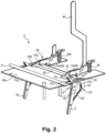
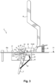
- Kupplungsvorrichtung (0), welche dazu dient, ein erstes und ein zweites Fahrzeug (100, 200) miteinander zu kuppeln, wobei die Kupplungsvorrichtung (0) zumindest einen Kupplungsmechanismus (40) und zumindest ein außerhalb des Kupplungsmechanismus (40) liegendes, erstes Kupplungsteil (21) umfasst, wobei die Kupplungsvorrichtung (0) dafür ausgelegt ist, wahlweise eine angekuppelte Konfiguration und eine abgekuppelte Konfiguration anzunehmen: in der angekuppelten Konfiguration ist der Kupplungsmechanismus (40) mit dem externen ersten Kupplungsteil (21) mechanisch verbunden und verhindert, dass sich dieses externe erste Kupplungsteil (21) von dem Kupplungsmechanismus (40) löst; in der abgekuppelten Konfiguration ist dieses externe erste Kupplungsteil (21) von dem Kupplungsmechanismus (40) gelöst, wobei die Kupplungsvorrichtung (0) ferner einen ersten Ständer (5) umfasst, der in Bezug auf den Kupplungsmechanismus (40) zwischen einer Einsatzstellung des ersten Ständers (5) und einer Verstauungsstellung des ersten Ständers (5) beweglich ist, dadurch gekennzeichnet, dass die Kupplungsvorrichtung (0) einen ersten Steuermechanismus (6) zur Bewegungssteuerung des ersten Ständers (5) enthält, der dafür ausgelegt ist, die Verfahrbewegung des ersten Ständers (5) von seiner Einsatzstellung in seine Verstauungsstellung zu steuern, während sich die Kupplungsvorrichtung (0) von ihrer abgekuppelten Konfiguration in ihre angekuppelte Konfiguration bewegt.
- Kupplungsvorrichtung (0) nach Anspruch 1, wobei der erste Steuermechanismus (6) zur Bewegungssteuerung des ersten Ständers (5) ferner dafür ausgelegt ist, die Verfahrbewegung des ersten Ständers (5) von seiner Verstauungsstellung in seine Einsatzstellung zu steuern, während sich die Kupplungsvorrichtung (0) von ihrer angekuppelten Konfiguration in ihre abgekuppelte Konfiguration bewegt.
- Kupplungsvorrichtung (0) nach einem der Ansprüche 1 oder 2, wobei der erste Steuermechanismus (6) einen ersten Riegel (61) enthält, der zwischen einer Verriegelungsposition des ersten Ständers (5) und einer Freigabeposition des ersten Ständers (5) beweglich ist, wobei dieser erste Riegel (61) dafür ausgelegt ist, den ersten Ständer (5) in seiner Einsatzstellung zu halten, wenn sich der erste Riegel (61) in der Verriegelungsposition des ersten Ständers (5) befindet.
- Kupplungsvorrichtung (0) nach Anspruch 3, wobei der erste Ständer (5) und der erste Riegel (61) derart ausgebildet sind, dass der erste Riegel erst dann von seiner Freigabeposition in seine Verriegelungsposition bewegt werden kann, wenn sich der erste Ständer (5) in seiner Einsatzstellung befindet.
- Kupplungsvorrichtung nach einem der Ansprüche 3 oder 4, wobei der erste Steuermechanismus (6) eine erste elastische Rückstelleinrichtung (62) enthält, die dafür ausgelegt ist, den ersten Riegel (61) von seiner Freigabeposition in seine Verriegelungsposition zurückzustellen.
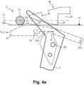
- Kupplungsvorrichtung (0) nach einem der Ansprüche 3 bis 5, wobei der erste Riegel (61) zumindest einen ersten Arm (61a) enthält, der um eine Drehachse (R1) dieses ersten Arms (61a) herum schwenkbar ist, wobei der Arm (61a) eine erste Einkerbung (61b) enthält, die auf eine Rastnase (51) des ersten Ständers auftrifft, wenn sich der erste Ständer (5) in seiner Einsatzstellung und der erste Riegel in seiner Verriegelungsposition befinden, wodurch der erste Ständer (5) in seiner Einsatzstellung verriegelt wird.
- Kupplungsvorrichtung (0) nach einem der Ansprüche 3 bis 6, enthaltend zumindest eine Führungsfläche (40a), die eine Laufbahn (T1) des externen ersten Kupplungsteils (21) in Bezug auf die Kupplungsvorrichtung (40) definiert, während sich dieses externe erste Kupplungsteil bis zu einem ersten Aufnahmeraum (43) zur Aufnahme des externen ersten Kupplungsteils (21) hin bewegt, in welchem das externe erste Kupplungsteil (21) aufgenommen ist, wenn sich die Kupplungsvorrichtung (0) in ihrer angekuppelten Konfiguration befindet, wobei sich ein Abschnitt (61c) des ersten Riegels (61) in Verriegelungsposition auf der Laufbahn (T1) des externen ersten Kupplungsteils (21) befindet, sodass, wenn sich das externe erste Kupplungsteil (21) auf der Führungsfläche (40a) entlang der Laufbahn (T1) des externen ersten Kupplungsteils (21) zu dem ersten Aufnahmeraum (43) hin bewegt, das externe Teil (21) mit diesem Abschnitt (61c) des ersten Riegels (61) in Kontakt tritt und dadurch den ersten Riegel (61) von seiner Verriegelungsposition in seine Freigabeposition bewegt.
- Kupplungsvorrichtung nach Anspruch 7, wobei der Steuermechanismus (6) zur Bewegungssteuerung des ersten Ständers (5) eine Betätigungsfläche (5X) enthält, welche, zumindest solange sich der erste Ständer (5) in seiner Einsatzstellung befindet, in der durch die Führungsfläche (40a) definierten Laufbahn (T1) des externen ersten Kupplungsteils (21) gelegen ist, wobei besagte Betätigungsfläche (5X) derart mit dem ersten Ständer in Wirkverbindung steht, dass unter der Einwirkung einer Schubkraft, die durch das externe erste Kupplungsteil (21) auf die Betätigungsfläche (5X) ausgeübt wird, wenn ersteres sich entlang der Laufbahn (T1) zu dem ersten Aufnahmeraum (43) hin bewegt, die Betätigungsfläche mitbewegt wird, wodurch der erste Ständer (5) von seiner Einsatzstellung in seine Verstauungsstellung übergeht.
- Kupplungsvorrichtung nach Anspruch 8, wobei die Betätigungsfläche (5X) durch den ersten Ständer (5) getragen wird.
- Kupplungsvorrichtung nach einem der Ansprüche 8 oder 9, wobei die Betätigungsfläche (5X) derart angeordnet ist, dass sie, zumindest solange sich der erste Ständer (5) in seiner Einsatzstellung befindet, zwischen dem Abschnitt (61c) des ersten Riegels (61) und dem ersten Aufnahmeraum (43) liegt.
- Kupplungsvorrichtung nach einem der Ansprüche 1 bis 10, wobei der erste Steuermechanismus (6) zur Bewegungssteuerung des ersten Ständers (5) ein elastisches Rückstellmittel (63) enthält, welches dazu dient, den ersten Ständer (5) von seiner Verstauungsstellung in seine Einsatzstellung zurückzustellen.
- Kupplungsvorrichtung (0) nach einem der Ansprüche 1 bis 11, wobei der erste Ständer (5) aus einem Stab besteht, der in Bezug auf eine an dem Kupplungsmechanismus befestigte Platte (64) schwenkbar montiert ist.
- Kupplungsvorrichtung nach einem der Ansprüche 1 bis 12, wobei der Kupplungsmechanismus (40) einen ersten Anschlag (41) und einen ersten Haken (42) enthält, der um eine Schwenkachse (Pvt40) des Kupplungsmechanismus (40) herum zwischen einer ersten Schwenkposition, welche zumindest dann erreicht ist, wenn sich die Kupplungsvorrichtung (0) in ihrer angekuppelten Konfiguration befindet, und einer zweiten Schwenkposition drehbar montiert ist, wobei, wenn sich der erste Haken (42) in der ersten Schwenkposition befindet, der erste Haken (42) derart angeordnet ist, dass das externe erste Kupplungsteil (21) zwischen dem ersten Haken (42) und dem ersten Anschlag (41) blockiert wird, und wenn sich der erste Haken (42) in der zweiten Schwenkposition befindet, der erste Haken (42) derart angeordnet ist, dass er eine freie Translation des externen ersten Kupplungsteils (21) in Bezug auf den Kupplungsmechanismus (40) zulässt, indem er sich von dem ersten Anschlag (41) löst.
- Kupplungsvorrichtung (0) nach Anspruch 13, wobei der Kupplungsmechanismus (40) einen von dem ersten Anschlag (41) beabstandeten, zweiten Anschlag (41b) und einen von dem ersten Haken (42) beabstandeten, zweiten Haken (42b) enthält, wobei der zweite Haken (42b) um eine zweite Schwenkachse (Pvt40b) des Kupplungsmechanismus (40) herum zwischen einer ersten Schwenkposition dieses zweiten Hakens (42b), welche zumindest dann erreicht ist, wenn sich die Kupplungsvorrichtung (0) in ihrer angekuppelten Konfiguration befindet, und einer zweiten Schwenkposition dieses zweiten Hakens (42b), drehbar montiert ist, wobei der zweite Haken (42b) in seiner ersten Schwenkposition derart angeordnet ist, dass er das externe erste Kupplungsteil (21) zwischen dem zweiten Haken (42b) und dem zweiten Anschlag (41b) blockiert, und wobei, wenn sich der zweiten Haken (42b) in der zweiten Schwenkposition befindet, der zweite Haken (42b) derart angeordnet ist, dass er eine freie Translation des externen ersten Kupplungsteils (21) in Bezug auf den Kupplungsmechanismus (40) zulässt, indem er sich von dem zweiten Anschlag (41b) löst.
- Kupplungsvorrichtung (0) nach einem der Ansprüche 1 bis 14, wobei das externe erste Kupplungsteil (21) stangenförmig ausgebildet ist, wobei der Kupplungsmechanismus (40) und das externe Teil (21) derart ausgebildet sind, dass, wenn sich der Kupplungsmechanismus (40) in der angekuppelten Konfiguration befindet und mit dem externen ersten Kupplungsteil (21) mechanisch verbunden ist, dieses stangenförmige erste Teil (21) in Bezug auf den Kupplungsmechanismus (40) um eine sich entlang der Länge der Stange erstreckenden Schwenkachse herum schwenkbar ist.
- Kupplungsvorrichtung nach einem der Ansprüche 13 oder 14, wobei der erste Steuermechanismus (6) zur Bewegungssteuerung des ersten Ständers (5) ein Bedienteil (44) enthält, welches dafür ausgelegt ist, den Übergang des ersten Hakens (42) von seiner ersten Position in seine zweite Position zu steuern.
- Kupplungsvorrichtung nach einem der Ansprüche 1 bis 15, wobei der Kupplungsmechanismus (40) ein Bedienteil (44) enthält, welches dafür ausgelegt ist, den Übergang von der angekuppelten Konfiguration in die abgekuppelte Konfiguration zu steuern.
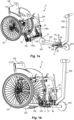
- Anordnung enthaltend ein zweites Fahrzeug (200) und eine Kupplungsvorrichtung (0) nach einem der Ansprüche 1 bis 17, wobei der Kupplungsmechanismus (40) von dem zweiten Fahrzeug (200) derart getragen wird, dass:- wenn sich die Kupplungsvorrichtung (0) in ihrer abgekuppelten Konfiguration befindet, das zweite Fahrzeug (200) in einer stabilen Position in Bezug auf einen dieses zweite Fahrzeug (200) tragenden Boden gehalten wird, und zwar mit Hilfe des von dem zweiten Fahrzeug getragenen, ersten Ständers (5), der sich in seiner Einsatzstellung befindet, in welcher er auf dem Boden abgestützt ist; und dass- wenn sich die Kupplungsvorrichtung (0) in ihrer angekuppelten Konfiguration befindet, das zweite Fahrzeug (200) an dem externen ersten Kupplungsteil (21) gekuppelt ist und sich der erste Ständer (5) in seiner Verstauungsstellung befindet, in welcher er von dem Boden beabstandet ist.
- Anordnung nach Anspruch 18, ferner enthaltend ein erstes Fahrzeug (100) mit zumindest einem Paar Hinterräder (101, 102) und mit zumindest einem Vorderrad (103), wobei das externe erste Teil an dem ersten Fahrzeug (100) befestigt ist.
Applications Claiming Priority (2)
| Application Number | Priority Date | Filing Date | Title |
|---|---|---|---|
| FR2000856A FR3106491A1 (fr) | 2020-01-29 | 2020-01-29 | Dispositif d’attelage de deux véhicules |
| PCT/EP2021/050984 WO2021151714A1 (fr) | 2020-01-29 | 2021-01-19 | Dispositif d'attelage de deux vehicules |
Publications (3)
| Publication Number | Publication Date |
|---|---|
| EP4096941A1 EP4096941A1 (de) | 2022-12-07 |
| EP4096941B1 true EP4096941B1 (de) | 2025-03-05 |
| EP4096941C0 EP4096941C0 (de) | 2025-03-05 |
Family
ID=69903678
Family Applications (1)
| Application Number | Title | Priority Date | Filing Date |
|---|---|---|---|
| EP21700595.8A Active EP4096941B1 (de) | 2020-01-29 | 2021-01-19 | Vorrichtung zum koppeln zweier fahrzeuge |
Country Status (3)
| Country | Link |
|---|---|
| EP (1) | EP4096941B1 (de) |
| FR (1) | FR3106491A1 (de) |
| WO (1) | WO2021151714A1 (de) |
Family Cites Families (4)
| Publication number | Priority date | Publication date | Assignee | Title |
|---|---|---|---|---|
| EP0629390A1 (de) * | 1993-06-04 | 1994-12-21 | Hendrik Jan Ordelman | Hilfsrahmen für einen Rollstuhl und Rollstuhl mit diesem Hilfsrahmen |
| KR101598484B1 (ko) * | 2014-06-23 | 2016-03-02 | 한국생산기술연구원 | 착탈 가능한 휠체어 주행보조장치 |
| FR3037311A1 (fr) * | 2015-06-09 | 2016-12-16 | Renault Sa | Dispositif d'accrochage d'une remorque a un vehicule tracteur et ensemble forme par l'attelage d'un vehicule tracteur et d'une remorque comprenant un tel dispositif |
| US9757290B1 (en) | 2015-07-24 | 2017-09-12 | Sergio Paolo Scognamiglio | Adjustable device for attaching a manual wheelchair to a scooter |
-
2020
- 2020-01-29 FR FR2000856A patent/FR3106491A1/fr active Pending
-
2021
- 2021-01-19 EP EP21700595.8A patent/EP4096941B1/de active Active
- 2021-01-19 WO PCT/EP2021/050984 patent/WO2021151714A1/fr not_active Ceased
Also Published As
| Publication number | Publication date |
|---|---|
| FR3106491A1 (fr) | 2021-07-30 |
| EP4096941C0 (de) | 2025-03-05 |
| WO2021151714A1 (fr) | 2021-08-05 |
| EP4096941A1 (de) | 2022-12-07 |
Similar Documents
| Publication | Publication Date | Title |
|---|---|---|
| EP3233617B1 (de) | Zusammenklappbarer tretroller | |
| FR3055877B1 (fr) | Accessoire pour poussette, ainsi qu'ensemble de transport comprenant une poussette et un tel accessoire | |
| EP3755575B1 (de) | Kippbarer anhänger mit mechanischer betätigungsvorrichtung und hochpositionsverriegelungvorrichtung | |
| FR2769268A1 (fr) | Siege repliable amovible | |
| FR3003801A1 (fr) | Poussette pour enfant transformable en remorque pour velo | |
| EP1447301B1 (de) | Kinderwagen mit Steuermittel zum Ver- und Entriegeln von Bremsanlagen, diese Mittel sind getrennt und in Nähe voneinander | |
| FR2892083A3 (fr) | Systeme de freinage pour une poussette de bebe | |
| FR2815584A1 (fr) | Siege de vehicule avec un support lateral et une boucle de ceinture | |
| EP4096941B1 (de) | Vorrichtung zum koppeln zweier fahrzeuge | |
| EP4147546A1 (de) | Drehpflug mit verbesserter sicherheit bei konfigurationsänderungen | |
| EP2489572B1 (de) | Fahrzeug mit manueller Hilfsstartvorrichtung | |
| EP2946994B1 (de) | Anhänger für zweirad-fahrzeug | |
| EP4057972B1 (de) | Verbindungssystem zum verbinden eines rollstuhls mit einem scooter, der mit mindestens einem motorisierten rad versehen ist | |
| WO2021094092A1 (fr) | Dispositif d'attelage adapté à être assemblé sur une trottinette | |
| EP0192006B1 (de) | Kraftfahrzeugsitz | |
| EP0965478A1 (de) | In Längsrichtung verstellbar Rücksitz in einem Kraftfahrzeuginnenraum | |
| EP4100306A1 (de) | Klappbares zweirädriges fahrzeug mit reduzierter grösse in der geklappten position | |
| EP3756973B1 (de) | Gelände-transportvorrichtung für ein kind in sitzender position | |
| FR3034723A1 (fr) | Dispositif de verrouillage de banquette arriere | |
| FR3024680A1 (fr) | Siege de vehicule automobile et vehicule automobile equipe d’un tel siege | |
| FR2795652A1 (fr) | Chariot pliable pour sac de golf, possedant des moyens de verrouillage perfectionnes | |
| EP2314501B1 (de) | Fahrzeugkombination mit einem Zugfahrzeug, einem Anhänger mit verschiebbarer Deichsel und einer Axialführungseinrichtung | |
| EP3199434B1 (de) | Anhänger, der mit schnellbefestigungsmitteln der zugstange auf einem fahrgestell ausgestattet ist | |
| FR3134162A1 (fr) | Dispositif de fixation d’un écran à un support | |
| WO2007125183A2 (fr) | Dispositif de blocage/liberation d'une chape de roue orientable et chariot brancard equipe d'un tel dispositif |
Legal Events
| Date | Code | Title | Description |
|---|---|---|---|
| STAA | Information on the status of an ep patent application or granted ep patent |
Free format text: STATUS: UNKNOWN |
|
| STAA | Information on the status of an ep patent application or granted ep patent |
Free format text: STATUS: THE INTERNATIONAL PUBLICATION HAS BEEN MADE |
|
| PUAI | Public reference made under article 153(3) epc to a published international application that has entered the european phase |
Free format text: ORIGINAL CODE: 0009012 |
|
| STAA | Information on the status of an ep patent application or granted ep patent |
Free format text: STATUS: REQUEST FOR EXAMINATION WAS MADE |
|
| 17P | Request for examination filed |
Effective date: 20220727 |
|
| AK | Designated contracting states |
Kind code of ref document: A1 Designated state(s): AL AT BE BG CH CY CZ DE DK EE ES FI FR GB GR HR HU IE IS IT LI LT LU LV MC MK MT NL NO PL PT RO RS SE SI SK SM TR |
|
| DAV | Request for validation of the european patent (deleted) | ||
| DAX | Request for extension of the european patent (deleted) | ||
| GRAP | Despatch of communication of intention to grant a patent |
Free format text: ORIGINAL CODE: EPIDOSNIGR1 |
|
| STAA | Information on the status of an ep patent application or granted ep patent |
Free format text: STATUS: GRANT OF PATENT IS INTENDED |
|
| INTG | Intention to grant announced |
Effective date: 20240604 |
|
| GRAJ | Information related to disapproval of communication of intention to grant by the applicant or resumption of examination proceedings by the epo deleted |
Free format text: ORIGINAL CODE: EPIDOSDIGR1 |
|
| STAA | Information on the status of an ep patent application or granted ep patent |
Free format text: STATUS: REQUEST FOR EXAMINATION WAS MADE |
|
| GRAP | Despatch of communication of intention to grant a patent |
Free format text: ORIGINAL CODE: EPIDOSNIGR1 |
|
| STAA | Information on the status of an ep patent application or granted ep patent |
Free format text: STATUS: GRANT OF PATENT IS INTENDED |
|
| INTC | Intention to grant announced (deleted) | ||
| RAP3 | Party data changed (applicant data changed or rights of an application transferred) |
Owner name: OMNI |
|
| INTG | Intention to grant announced |
Effective date: 20241104 |
|
| GRAS | Grant fee paid |
Free format text: ORIGINAL CODE: EPIDOSNIGR3 |
|
| GRAA | (expected) grant |
Free format text: ORIGINAL CODE: 0009210 |
|
| STAA | Information on the status of an ep patent application or granted ep patent |
Free format text: STATUS: THE PATENT HAS BEEN GRANTED |
|
| AK | Designated contracting states |
Kind code of ref document: B1 Designated state(s): AL AT BE BG CH CY CZ DE DK EE ES FI FR GB GR HR HU IE IS IT LI LT LU LV MC MK MT NL NO PL PT RO RS SE SI SK SM TR |
|
| REG | Reference to a national code |
Ref country code: GB Ref legal event code: FG4D Free format text: NOT ENGLISH |
|
| REG | Reference to a national code |
Ref country code: CH Ref legal event code: EP |
|
| REG | Reference to a national code |
Ref country code: IE Ref legal event code: FG4D Free format text: LANGUAGE OF EP DOCUMENT: FRENCH |
|
| REG | Reference to a national code |
Ref country code: DE Ref legal event code: R096 Ref document number: 602021027107 Country of ref document: DE |
|
| U01 | Request for unitary effect filed |
Effective date: 20250307 |
|
| U07 | Unitary effect registered |
Designated state(s): AT BE BG DE DK EE FI FR IT LT LU LV MT NL PT RO SE SI Effective date: 20250314 |
|
| PG25 | Lapsed in a contracting state [announced via postgrant information from national office to epo] |
Ref country code: RS Free format text: LAPSE BECAUSE OF FAILURE TO SUBMIT A TRANSLATION OF THE DESCRIPTION OR TO PAY THE FEE WITHIN THE PRESCRIBED TIME-LIMIT Effective date: 20250605 |
|
| PG25 | Lapsed in a contracting state [announced via postgrant information from national office to epo] |
Ref country code: ES Free format text: LAPSE BECAUSE OF FAILURE TO SUBMIT A TRANSLATION OF THE DESCRIPTION OR TO PAY THE FEE WITHIN THE PRESCRIBED TIME-LIMIT Effective date: 20250305 |
|
| PG25 | Lapsed in a contracting state [announced via postgrant information from national office to epo] |
Ref country code: NO Free format text: LAPSE BECAUSE OF FAILURE TO SUBMIT A TRANSLATION OF THE DESCRIPTION OR TO PAY THE FEE WITHIN THE PRESCRIBED TIME-LIMIT Effective date: 20250605 |
|
| PG25 | Lapsed in a contracting state [announced via postgrant information from national office to epo] |
Ref country code: HR Free format text: LAPSE BECAUSE OF FAILURE TO SUBMIT A TRANSLATION OF THE DESCRIPTION OR TO PAY THE FEE WITHIN THE PRESCRIBED TIME-LIMIT Effective date: 20250305 |
|
| PG25 | Lapsed in a contracting state [announced via postgrant information from national office to epo] |
Ref country code: GR Free format text: LAPSE BECAUSE OF FAILURE TO SUBMIT A TRANSLATION OF THE DESCRIPTION OR TO PAY THE FEE WITHIN THE PRESCRIBED TIME-LIMIT Effective date: 20250606 |
|
| PG25 | Lapsed in a contracting state [announced via postgrant information from national office to epo] |
Ref country code: SM Free format text: LAPSE BECAUSE OF FAILURE TO SUBMIT A TRANSLATION OF THE DESCRIPTION OR TO PAY THE FEE WITHIN THE PRESCRIBED TIME-LIMIT Effective date: 20250305 |
|
| PG25 | Lapsed in a contracting state [announced via postgrant information from national office to epo] |
Ref country code: PL Free format text: LAPSE BECAUSE OF FAILURE TO SUBMIT A TRANSLATION OF THE DESCRIPTION OR TO PAY THE FEE WITHIN THE PRESCRIBED TIME-LIMIT Effective date: 20250305 |
|
| PG25 | Lapsed in a contracting state [announced via postgrant information from national office to epo] |
Ref country code: CZ Free format text: LAPSE BECAUSE OF FAILURE TO SUBMIT A TRANSLATION OF THE DESCRIPTION OR TO PAY THE FEE WITHIN THE PRESCRIBED TIME-LIMIT Effective date: 20250305 |
|
| PG25 | Lapsed in a contracting state [announced via postgrant information from national office to epo] |
Ref country code: SK Free format text: LAPSE BECAUSE OF FAILURE TO SUBMIT A TRANSLATION OF THE DESCRIPTION OR TO PAY THE FEE WITHIN THE PRESCRIBED TIME-LIMIT Effective date: 20250305 |
|
| PG25 | Lapsed in a contracting state [announced via postgrant information from national office to epo] |
Ref country code: IS Free format text: LAPSE BECAUSE OF FAILURE TO SUBMIT A TRANSLATION OF THE DESCRIPTION OR TO PAY THE FEE WITHIN THE PRESCRIBED TIME-LIMIT Effective date: 20250705 |
|
| PLBE | No opposition filed within time limit |
Free format text: ORIGINAL CODE: 0009261 |
|
| STAA | Information on the status of an ep patent application or granted ep patent |
Free format text: STATUS: NO OPPOSITION FILED WITHIN TIME LIMIT |
|
| REG | Reference to a national code |
Ref country code: CH Ref legal event code: L10 Free format text: ST27 STATUS EVENT CODE: U-0-0-L10-L00 (AS PROVIDED BY THE NATIONAL OFFICE) Effective date: 20260114 |
|
| 26N | No opposition filed |
Effective date: 20251208 |