EP4096880B1 - Schneidwerkzeug - Google Patents
Schneidwerkzeug Download PDFInfo
- Publication number
- EP4096880B1 EP4096880B1 EP20811338.1A EP20811338A EP4096880B1 EP 4096880 B1 EP4096880 B1 EP 4096880B1 EP 20811338 A EP20811338 A EP 20811338A EP 4096880 B1 EP4096880 B1 EP 4096880B1
- Authority
- EP
- European Patent Office
- Prior art keywords
- blade
- cutting tool
- adapter
- rope
- handle
- Prior art date
- Legal status (The legal status is an assumption and is not a legal conclusion. Google has not performed a legal analysis and makes no representation as to the accuracy of the status listed.)
- Active
Links
Images


Classifications
-
- B—PERFORMING OPERATIONS; TRANSPORTING
- B26—HAND CUTTING TOOLS; CUTTING; SEVERING
- B26B—HAND-HELD CUTTING TOOLS NOT OTHERWISE PROVIDED FOR
- B26B15/00—Hand-held shears with motor-driven blades
Definitions
- the present disclosure relates to a cutting tool. More specifically, the present disclosure relates to the cutting tool which allows ease of blade replacement for common users.
- Cutting tools such as secateurs, loppers, rakes, pliers are used for performing cutting action using one or more blades. Put simply, such tools provide increased mechanical assistance and ease of operation to a common user to conveniently perform operations on objects such as branches having varying dimensions. Further, the cutting tools provide benefits such as trapping bypass cutting or simply "bypass" which allows pruning/cutting by the cutting tools while holding an object (i.e. branch) with one of the cutting edges.
- the '793 reference provides a cutting tool.
- the cutting tool includes an enclosure.
- the cutting tool further includes a first blade and a second blade.
- the cutting tool further includes a dowel clamping piece. At least one of the first blade and the second blade is replaceable. The dowel clamping piece is taken out to pull at least one of the first blade and the second blade.
- the '793 reference falls short of providing a smooth and safe application with user-friendly replacement of blade(s) of the cutting tool.
- a further example of prior art is given by the patent documentation WO2018/205126A1
- the cutting tool includes a first blade.
- the cutting tool further includes a second blade.
- the second blade is pivotally coupled to the first blade.
- the first blade and the second blade together perform a cutting action on an object placed between them.
- the cutting tool further includes a drive unit.
- the drive unit is operatively coupled to at least one of the first blade and the second blade.
- the drive unit is configured to selectively provide a supplemental motor force to assist a movement of at least one of the first blade and the second blade to perform the cutting action.
- the cutting tool further includes a rope.
- the rope is operatively coupled to the drive unit.
- the rope provides force for a movement of the first blade.
- the cutting tool is characterized in that an adapter is operatively coupling the first blade with the rope.
- the adapter has an opening to removably fit the first blade with the adapter.
- the adapter allows on-demand replacement of the first blade through the opening of the adapter.
- a connection element that may include a removable nut and/or screw is provided outside of a handle of the cutting tool or is provided accessible from outside of a handle of the cutting tool.
- the removable connection element that may include a removable nut and/or screw can be provided at the pivoted position of the first blade and the second blade.
- the removable connection element, in particular a nut and/or screw allows ejection of the first blade on disassembly of the removable connection element or is configured to allow ejection of the first blade on disassembly of the removable connection element. So, the removable nut and/or screw provides a convenient arrangement to eject the first blade without any deformations of other parts of the cutting tool.
- the drive unit includes a motor, a gearbox, a drum, a printed circuit board assembly (PCBA) and a battery to selectively provide the supplemental motor force.
- This supplemental motor force by the drive unit provides the mechanical advantage to assist cutting action by the blades.
- the cutting tool includes a slider or trigger to activate or deactivate the drive unit. This allows to have a safe and convenient operation of the cutting tool with the provision of the slider or trigger.
- the cutting tool includes a top handle and a bottom handle which are operatively coupled with the second blade and the first blade respectively.
- the cutting tool can be provided in the form of a garden shears or a secateurs to be operated manually and one-handed.
- the first blade is releasably coupled to the second blade and/or the the first blade is releasably coupled to a handle, in particular to the bottom handle and/or wherein the first blade is releasably coupled to the adapter.
- the first blade is enabled to be released from the cutting tool, such that a replacement blade can be coupled to the cutting tool if appropriate.
- all components of the drive unit are housed in a single handle, in particular in the top handle. Accordingly, it is possible to provide the bottom handle as a very slim handle. Further, mounting of the drive unit may be simplified if arranged in the same handle.
- the adapter is formed to couple to a loop formed by the rope in particular in that the rope forms a loop around the adapter.
- the adapter has a sleeve-like form or is a sleeve, in particular wherein the first blade passes through two openings formed in a substantially cylindrical wall of the adapter to removably fit the first blade with the adapter.
- the adapter is sufficiently rigid and enables to receive and transfer a force from the rope to the blade coupled to the adapter. Further, the blade can be coupled easily to the adapter.
- the adapter comprises a, preferably circumferential, recess in which the rope, in particular the loop formed by the rope, is arranged. In this way, the rope can be attached to a seat formed within the adapter, thereby preventing the rope from slipping off the adapter.
- the adapter comprises one or two cutout(s), in particular provided in the cylindrical wall of the adapter, in which the rope, in particular the loop formed by the rope, may be arranged such that the rope is prevented from sliding off the adapter. Also these elements allow attachment of the rope to an adapter, wherein the rope may be prevented from slipping off the adapter.
- the adapter is attached to the bottom handle and to the first blade in such way as to allow, in particular pivotal, movement of the first blade relative to the bottom handle.
- a movement of the blade relative to the bottom handle may be detected by a switch, enabling determination of the manual force applied to the handle and thereby enabling determination whether an assisting force to be supplied by the cutting tool shall be added to the manual force or not.
- This effect is in particular achieved in that, in a mounted state of the first blade, the adapter is attached to the first blade such that the adapter cannot move relative to the first blade, but wherein the adapter is attached to the bottom handle such that it is enabled to move relative to the handle, at least when the first blade moves relative to the bottom handle. It shall be appreciated that it is possible that the adapter is not directly attached to the bottom handle, but only indirectly via the first blade, or that the adapter is only in touch with, but not fixed to the bottom handle.
- the adapter comprises a hollow space which is configured to receive at least a part of a spring of the cutting tool, at least in a fully compressed state of the spring.
- the spring can be accommodated partially within the adapter and the bottom handle, allowing a compact design of the cutting tool.
- the adapter is provided with a tube element which extends from opening to opening, in particular through which the first blade passes such that the rope is mechanically separated from the shaft when the shaft is moved out of or into the adapter.
- the rope is protected from damage by the blade passing through the adapter and possibly entangling with the rope.
- the passage formed by the adapter for the first blade is configured to ensure that an end of a shaft of the first blade connects with a connector positioned within the bottom handle, in particular positioned within an end portion of the bottom handle.
- a switch or the like may be arranged within an end region of the bottom handle, that shall detect relative movement between the bottom handle and the first blade, it is advantageous when the first blade is guided during passage through the bottom handle towards the switch part for connection with the first blade.
- connection of the first blade with the connector of the switch is simplified.
- FIG. 1 illustrates a cutting tool 100.
- the cutting tool 100 of the present disclosure is illustrated as secateurs, however, the present disclosure may be readily applied to any cutting tool 100 such as, but not limited to, a lopper, shear, scissor etc. with two or more cutting edges.
- the cutting tool 100 includes one or more blades i.e. a first blade 102 and a second blade 104.
- the second blade 104 is pivotally coupled to the first blade 102.
- the first blade 102 and the second blade 104 together perform a cutting action on an object (generally branches and the like) placed between them.
- the cutting tool 100 further includes a removable nut and/or screw 106.
- the removable nut and/or screw 106 is provided at the pivoted position of the first blade 102 and the second blade 104.
- the removable nut and/or screw 106 allows ejection of the first blade 102 (best illustrated through FIGS. 4 , and 5 ) on disassembly of the removable nut and/or screw 106.
- the removable nut and/or screw 106 provides a convenient arrangement to eject the first blade 102 without any deformations of other parts of the cutting tool 100.
- the removable nut and/or screw 106 may be any one or more of a coupling nut, a flange nut, a hex nut, a lock nut, a slotted nut, a square nut, a wheel nut and the like.
- the cutting tool 100 includes one or more handles i.e. a top handle 108 and a bottom handle 110 which are operatively coupled with the second blade 104 and the first blade 102 respectively.
- the cutting tool 100 further includes a lid 132.
- the one or more blades i.e. the first blade 102 and the second blade 104 may be one or more of a clip point blade, a drop point blade, a gut hook blade, a hawkbell blade, a needle point blade, a straight back blade, a sheepsfoot blade, a spear point blade or any other blade as used or known in the art.
- the first blade 102 and the second blade 104 may be made of steel or any other material as used or known in the art. Choice of the material for any of the first blade 102 and the second blade 104 will generally depend upon factors such as life, application, weight or other parameters related to the cutting tool 100. However, the present disclosure is not to be limited by the type of the first blade 102 and the second blade 104 in any manner.
- first blade 102 and the second blade 104 may be a fixed blade while the other performs desired cutting action. Alternately or additionally, both the first blade 102 and the second blade 104 may be movable during the cutting action.
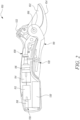
- FIG. 2 illustrates the cutting tool 100 which includes a drive unit 130.
- the drive unit 130 includes a motor 112 and a gearbox 114.
- the drive unit 130 further includes a drum 116 comprising a clutch, a retraction spring and a winch.
- the drive unit 130 includes a printed circuit board assembly (PCBA) 118 and a battery 120.
- the battery 120 is covered by the lid 132, as will be evident through combined reference to FIGS. 1 , 2 .
- the lid 132 may be assembled, disassembled to gain access to the battery 120.
- the lid 132 may be assembled or disassembled with the top handle 108 using any connection such as, but not limited to, sliding, snap-fits, magnetic coupling, push-fits and the like.
- the drive unit 130 may be operatively coupled to at least one of the first blade 102 and the second blade 104.
- the drive unit 130 is configured to selectively provide a supplemental motor force to assist a movement of at least one of the first blade 102 and the second blade 104 to perform the cutting action.
- the cutting tool 100 could also include a slider or trigger to activate or deactivate the drive unit 130.
- this slider or trigger is realized in top of the cutting tool 100 as slider or trigger 122, alternatively it as well could be realized as a slider or trigger.
- the drive unit 130 On engaging, moving or pressing the slider or trigger 122 the drive unit 130 gets switched on and off and thus the cutting tool 100 becomes convenient and safe to handle by common users.
- the drive unit 130 may be deactivated for instances which may require to save/extend battery life or allow uninterrupted operation of the power-assisted cutting tool 100, such as for low battery conditions.
- the motor 112 will remain in a disengaged/OFF state leading to a purely user-based cutting action by the cutting tool 100, without any supplemental motor force.
- the slider or trigger 122 might also look the cutting tool 100 in a closed status.
- the slider or trigger 122 may be a button, a knob, a single pole single throw switch, a single pole double throw switch, a double pole single throw switch, a double pole double throw switch, a push-button switch, a toggle switch, a limit switch, a float switch, and the like.
- a button, a knob, or any other switching means as used or known in the relevant art may be present in place of the switch 122.
- all components of the drive unit 130 are housed in a single handle i.e. the top handle 108 as best illustrated in FIG. 2 with the cutting tool being in closed status.
- This advantageous ergonomic profile can be seen with the side view of the cutting tool 100 of FIG. 2 .By this it also becomes possible to realize the first handle 108 as a slim bottom handle that allows the operation of the cutting tool even with small hands
- FIG. 3 illustrates details with the bottom handle 110 (shown in the bottom of the drawing) and the top handle 108 (shown on the top of the drawing) of the cutting tool 100 in a closed position.
- the cutting tool 100 having a spring 124.
- the cutting tool 100 further includes a rope 126 transmitting the force from the drive unit 130 inside the top handle 108 into the bottom handle 110 and an adapter 128 inside of the bottom handle 110.
- the adapter 128 is arranged inside of a cavity formed by the bottom handle 110.
- the adapter 128 finds application for pre-fixing the spring 124 and the rope 126 with the bottom handle 110, without any direct engagement or contact of the spring 124 and the rope 126 with the bottom handle 110, as best illustrated in FIG. 3 .
- the first blade 102 comprises a holding section which is insertable into and is, as shown in FIG. 3 , arranged inside of a blade seat formed by a cavity provided by the bottom handle 110.
- the holding section is firmly attached to the bottom handle 110 in order not provide any backlash between first blade 102 and bottom handle 110.
- the first blade 102 is passing through the adapter 128.
- the piercing of the first blade 102 through the adapter 128 helps in securing or locking of the first blade 102 within the adapter 128, and/or the bottom handle 110 as per the requirement.
- the holding section of the first blade 102 may have a substantially flat cross section with a height relatively large compared to a width of the cross section.
- the holding section can be arranged inside the cavity and pass through the adapter such that the direction of the force transferred by the rope 126 is effective substantially parallel to the extension of the height of the cross section of the holding section.
- the force transferred by the rope 126 via the adapter 128 to the first blade 102 acts substantially perpendicular relative to a longitudinal extension of the holding section of the first blade 102.
- a connection of the adapter 128 with the first blade 102 may be achieved by pushing, sliding, and piercing the first blade 102 through the adapter 128.
- the adapter 128 may be made up of one or more of a material like plastic, rubber, glass and the like. Additionally, or alternatively, the first blade 102 may slide, pierce, pass into the adapter 128.
- the adapter 128 allows the smooth movement or disassembly of the first blade 102 by simple pulling action on the first blade 102, after removal of the removal nut and/or screw 106 as illustrated in FIG. 4 .
- the removable nut and/or screw 106 may be disassembled by use of hand tools or by any other way convenient for the common user.
- the first blade 102 may be disassembled from the cutting tool 100, as illustrated in FIG. 5 . Then, the disassembled first blade 102 allows its substitution with another blade which may be another first blade 102 (not shown), which may have a sharp cutting edge or any other desired feature.
- the substituted blade i.e. the another first blade 102, for the replaced first blade 102 may have different design, profile etc. with same basic features, or structure which may allow it to desirably engage with the adapter 128.
- FIG. 5 illustrates the disassembling of the first blade 102 from the cutting tool 100.
- the first blade 102 may be removed or discarded by pushing, sliding the first blade 102 manually or by providing a button (not shown) which on pressing takes the first blade 102 out.
- the first blade 102 can be moved into the cavity or removed therefrom by a movement substantially parallel or slightly slanted relative to a longitudinal axis of the bottom handle 110.
- the adapter 128 is arranged inside of the cavity of the bottom handle 110 in such way that the holding section of the first blade 102 can pass through the adapter 128 by the same movement.
- the adapter 128 may have a ring shaped form with a circumferential recess, wherein a section, e.g.
- an end section, of the rope 126 can be accommodated.
- the end section of the rope 126 may be slung around the adapter 128 and may be fixed to another section of the rope 126 by a knot or a clamp, thus, forming a loop or a turn for transmitting the force from the rope 126 to the adapter 128.
- an indicator (not shown) may be provided to confirm the configuration of the substituted blade (i.e. the another first blade 102 ), for the first blade 102.
- the indicator may indicate either that the first blade 102 is in a working state or not.
- the indications may be given by different ways like buzzing, flashing a light, change of color and any such techniques as known or used in the art.
- the adapter 128 is provided as a sleeve which is arranged within the bottom handle 110.
- the bottom handle 110 has an opening having a corresponding form to accommodated the sleeve.
- the sleeve comprises a circumferential recess in which the rope 126 is embedded and guided around the shaft of the first blade 102.
- the sleeve may have one or two cutouts 134 such that the circumference in a height direction of the sleeve is reduced in the region of the cutout(s) 134.
- the sleeve further may have an inner diameter dimensioned such that the spring 124 can enter an inner hollow space of the sleeve when the cutting tool 100 is in a closed position and when the spring 124 is in a fully compressed state.
- the sleeve further may have two openings on its cylindrical wall through which the shaft of the first blade 102 passes.
- the shaft of the first blade 102 can be extracted from the sleeve or slid or pushed into the sleeve without getting entangled with the rope 126.
- Fig. 7 illustrates a connector 136 that may be connected to the end of the shaft of the first blade 102.
- the connector 136 may form a counterpart of a switch element 138 being fixedly attached to the bottom handle 110.
- the bottom handle 110 may move relative to the shaft of the first blade 102 such that the switch 138 operably couples to or cooperates with the connector causing a signal to be send via a cable 140 to a control of the cutting tool in order to start supply of the motor force assisting to the manual cutting process.
- Fig. 7 the default state of switch 138 and connector 136 are shown. This means that, if no manual force is applied to the top and bottom handles 108, 110, switch 138 and connector 136 are operably decoupled such that no signal or only a default signal is transmitted via the cable 140.
- the connector 136 is arranged in such way that the end of the shaft of the first blade 102 can connect with the connector 136 when being inserted into the bottom handle 110.
- connector 136 and the end of the shaft may comprise corresponding forms for establishing a plug-in connection.
Landscapes
- Life Sciences & Earth Sciences (AREA)
- Forests & Forestry (AREA)
- Engineering & Computer Science (AREA)
- Mechanical Engineering (AREA)
- Scissors And Nippers (AREA)
- Knives (AREA)
- Harvester Elements (AREA)
Claims (14)
- Schneidwerkzeug (100), umfassend:eine erste Klinge (102);eine zweite Klinge (104), die an die erste Klinge (102) schwenkbar gekoppelt ist, wobei die erste Klinge (102) und die zweite Klinge (104) zusammen eine Schneideaktion an einem dazwischen platzierten Objekt durchführen;einen oberen Griff (108) und einen unteren Griff (110), die mit der zweiten Klinge (104) beziehungsweise der ersten Klinge (102) wirkgekoppelt sind;eine Antriebseinheit (130), die an mindestens eine der ersten Klinge (102) und der zweiten Klinge (104) wirkgekoppelt ist, wobei die Antriebseinheit (130) konfiguriert ist, um eine zusätzliche Motorkraft wahlweise bereitzustellen, um eine Bewegung von mindestens einer der ersten Klinge (102) und der zweiten Klinge (104) zu unterstützen, um die Schneideaktion durchzuführen; undein Seil (126), das an die Antriebseinheit (130) wirkgekoppelt ist, wobei das Seil (126) eine Kraft für eine Bewegung der ersten Klinge (102) bereitstellt;einen Adapter (128), der die erste Klinge (102) mit dem Seil (126) wirkkoppelt;wobei die erste Klinge (102) an die zweite Klinge (104) lösbar gekoppelt ist und wobei die erste Klinge (102) an einen Griff lösbar gekoppelt ist und wobei die erste Klinge (102) an den Adapter (128) lösbar gekoppelt ist.
- Schneidwerkzeug (100) nach Anspruch 1, wobei der Adapter (128) eine Öffnung aufweist, um die erste Klinge (102) mit dem Adapter (128) ausbaubar einzupassen.
- Schneidwerkzeug (100) nach einem der vorstehenden Ansprüche, wobei ein ausbaubares Verbindungselement, insbesondere eine ausbaubare Mutter und/oder Schraube (106), außerhalb eines Griffs (108, 100) des Schneidwerkzeugs (100) bereitgestellt ist oder von außerhalb eines Griffs (108, 100) des Schneidwerkzeugs (100) zugänglich bereitgestellt ist
und/oderwobei das ausbaubare Verbindungselement, insbesondere eine ausbaubare Mutter und/oder Schraube (106), an der geschwenkten Position der ersten Klinge (102) und der zweiten Klinge (104) bereitgestellt ist,wobei das ausbaubare Verbindungselement ein Entfernen der ersten Klinge (102) bei einer Demontage des ausbaubaren Verbindungselements ermöglicht. - Schneidwerkzeug (100) nach einem der vorstehenden Ansprüche, wobei die Antriebseinheit (130) einen Motor (112), ein Getriebe (114), eine Trommel (116), eine bestückte Leiterplatte (PCBA) (118) und eine Batterie (120) umfasst, um die zusätzliche Motorkraft wahlweise bereitzustellen.
- Schneidwerkzeug (100) nach einem der vorstehenden Ansprüche, wobei das Schneidwerkzeug (100) einen Schieber oder einen Auslöser (122), um die Antriebseinheit (130) zu aktivieren oder deaktivieren, umfasst.
- Schneidwerkzeug (100) nach einem der vorstehenden Ansprüche, wobei die erste Klinge (102) an den unteren Griff (110) lösbar gekoppelt ist.
- Schneidwerkzeug (100) nach Anspruch 4, wobei alle Komponenten der Antriebseinheit (130) in einem einzigen Griff, insbesondere in dem oberen Griff (108), untergebracht sind.
- Schneidwerkzeug (100) nach einem der vorstehenden Ansprüche, wobei der Adapter (128) ausgebildet ist, um an eine durch das Seil (126) ausgebildete Schleife zu koppeln, insbesondere insofern, dass das Seil (126) eine Schleife um den Adapter (128) herum ausbildet.
- Schneidwerkzeug (100) nach einem der vorstehenden Ansprüche, wobei der Adapter (128) eine hülsenartige Form aufweist oder eine Hülse ist, insbesondere wobei die erste Klinge (102) durch zwei Öffnungen verläuft, die in einer im Wesentlichen zylindrischen Wand des Adapters (128) ausgebildet sind, um die erste Klinge (102) mit dem Adapter (128) ausbaubar einzupassen.
- Schneidwerkzeug (100) nach einem der vorstehenden Ansprüche, wobei der Adapter (128) eine vorzugsweise umlaufende Aussparung, in der das Seil (126), insbesondere die durch das Seil (126) ausgebildete Schleife, angeordnet ist, umfasst und/oder
wobei der Adapter (128) einen oder zwei Ausschnitte (134) umfasst, die insbesondere in der zylindrischen Wand des Adapters (128) bereitgestellt sind, in denen das Seil (126), insbesondere die durch das Seil (126) ausgebildete Schleife, derart angeordnet sein kann, dass das Seil (126) daran gehindert wird, von dem Adapter (126) abzugleiten. - Schneidwerkzeug (100) nach einem der vorstehenden Ansprüche, wobei der Adapter (128) an dem unteren Griff (110) und an der ersten Klinge (102) derart befestigt ist, dass die, insbesondere schwenkende, Bewegung der ersten Klinge (102) relativ zu dem unteren Griff (110) ermöglicht wird.
- Schneidwerkzeug (100) nach einem der vorstehenden Ansprüche, wobei der Adapter (128) einen Hohlraum umfasst, der konfiguriert ist, um mindestens einen Teil einer Feder (124) des Schneidwerkzeugs mindestens in einem vollständig komprimierten Zustand der Feder (124) aufzunehmen.
- Schneidwerkzeug (100) nach einem der vorstehenden Ansprüche, wobei der Adapter (128) mit einem Rohrelement versehen ist, das sich von Öffnung zu Öffnung erstreckt, durch die insbesondere die erste Klinge (102) derart verläuft, dass das Seil (126) von dem Schaft mechanisch getrennt wird, wenn der Schaft aus dem Adapter (128) oder in diesen bewegt wird.
- Schneidwerkzeug (100) nach einem der vorstehenden Ansprüche, wobei der durch den Adapter (128) für die erste Klinge (102) ausgebildete Durchgang konfiguriert ist, um sicherzustellen, dass ein Ende eines Schafts der ersten Klinge (102) mit einem Verbinder (136) verbunden ist, der innerhalb des unteren Griffs (110) positioniert ist, insbesondere innerhalb eines Endabschnitts des unteren Griffs (110) positioniert ist.
Applications Claiming Priority (2)
| Application Number | Priority Date | Filing Date | Title |
|---|---|---|---|
| EP20154313.9A EP3858560A1 (de) | 2020-01-29 | 2020-01-29 | Schneidwerkzeug |
| PCT/EP2020/083459 WO2021151546A1 (en) | 2020-01-29 | 2020-11-26 | Cutting tool |
Publications (2)
| Publication Number | Publication Date |
|---|---|
| EP4096880A1 EP4096880A1 (de) | 2022-12-07 |
| EP4096880B1 true EP4096880B1 (de) | 2023-12-20 |
Family
ID=69400407
Family Applications (2)
| Application Number | Title | Priority Date | Filing Date |
|---|---|---|---|
| EP20154313.9A Withdrawn EP3858560A1 (de) | 2020-01-29 | 2020-01-29 | Schneidwerkzeug |
| EP20811338.1A Active EP4096880B1 (de) | 2020-01-29 | 2020-11-26 | Schneidwerkzeug |
Family Applications Before (1)
| Application Number | Title | Priority Date | Filing Date |
|---|---|---|---|
| EP20154313.9A Withdrawn EP3858560A1 (de) | 2020-01-29 | 2020-01-29 | Schneidwerkzeug |
Country Status (5)
| Country | Link |
|---|---|
| EP (2) | EP3858560A1 (de) |
| CN (1) | CN115038561B (de) |
| FI (1) | FI4096880T3 (de) |
| PL (1) | PL4096880T3 (de) |
| WO (1) | WO2021151546A1 (de) |
Family Cites Families (11)
| Publication number | Priority date | Publication date | Assignee | Title |
|---|---|---|---|---|
| CH511100A (de) * | 1969-04-25 | 1971-08-15 | Styner & Bienz Ag | Elektrisches Schergerät |
| GB2404613A (en) * | 2003-07-14 | 2005-02-09 | David Jarman | A vegetation pruning device |
| US8069573B2 (en) * | 2009-07-21 | 2011-12-06 | Jiin Haur Industrial Co., Ltd. | Pruning hook with two operation modes |
| FI124699B (fi) * | 2011-06-30 | 2014-12-15 | Iittala Group Oy Ab | Leikkuutyökalu |
| CN102884948B (zh) * | 2011-07-22 | 2014-08-27 | 南京德朔实业有限公司 | 电动修枝剪刀 |
| FR3007242B1 (fr) * | 2013-06-19 | 2015-06-12 | Midi Ingenierie | Outil de coupe motorise electroportatif destine notamment a la taille de vegetaux |
| US20160219793A1 (en) | 2015-02-03 | 2016-08-04 | Ma Xianpeng | High-torsion electric pruning shears |
| FR3034285B1 (fr) * | 2015-04-01 | 2017-03-17 | Pellenc Sa | Dispositif de maintien d'une lame de coupe pivotante |
| DE102016211975A1 (de) * | 2016-06-30 | 2018-01-04 | Robert Bosch Gmbh | Schneidvorrichtung |
| CN106305166A (zh) * | 2016-10-21 | 2017-01-11 | 方培锵 | 一种低枝剪 |
| DE17908810T1 (de) * | 2017-05-09 | 2020-03-19 | Tti (Macao Commercial Offshore) Limited | Elektrowerkzeug und antriebsmechanismus zur verwendung in einem elektrowerkzeug |
-
2020
- 2020-01-29 EP EP20154313.9A patent/EP3858560A1/de not_active Withdrawn
- 2020-11-26 PL PL20811338.1T patent/PL4096880T3/pl unknown
- 2020-11-26 EP EP20811338.1A patent/EP4096880B1/de active Active
- 2020-11-26 WO PCT/EP2020/083459 patent/WO2021151546A1/en not_active Ceased
- 2020-11-26 CN CN202080095096.8A patent/CN115038561B/zh active Active
- 2020-11-26 FI FIEP20811338.1T patent/FI4096880T3/fi active
Also Published As
| Publication number | Publication date |
|---|---|
| FI4096880T3 (fi) | 2024-01-24 |
| CN115038561A (zh) | 2022-09-09 |
| EP3858560A1 (de) | 2021-08-04 |
| EP4096880A1 (de) | 2022-12-07 |
| WO2021151546A1 (en) | 2021-08-05 |
| CN115038561B (zh) | 2023-07-18 |
| PL4096880T3 (pl) | 2024-03-25 |
Similar Documents
| Publication | Publication Date | Title |
|---|---|---|
| EP1762136B1 (de) | Motorisiertes Werkzeug mit auswechselbaren Messerklingen und Verfahren | |
| US20250366404A1 (en) | Cutting tool | |
| US8069571B2 (en) | Spring back safety and film cutter | |
| EP2454934B1 (de) | Pflanzenschneider | |
| EP4096880B1 (de) | Schneidwerkzeug | |
| EP4096879B1 (de) | Schneidwerkzeug | |
| CN110113937B (zh) | 手持工具 | |
| EP0984345A1 (de) | Sicherheitssperrvorrichtung für einen Hebelschater | |
| CN117042594B (zh) | 切割工具 | |
| EP3858133A1 (de) | Schneidwerkzeug | |
| CN107208681B (zh) | 用于工作工具的伸缩杆组件 | |
| CN117082965A (zh) | 园艺工具 |
Legal Events
| Date | Code | Title | Description |
|---|---|---|---|
| STAA | Information on the status of an ep patent application or granted ep patent |
Free format text: STATUS: UNKNOWN |
|
| STAA | Information on the status of an ep patent application or granted ep patent |
Free format text: STATUS: THE INTERNATIONAL PUBLICATION HAS BEEN MADE |
|
| PUAI | Public reference made under article 153(3) epc to a published international application that has entered the european phase |
Free format text: ORIGINAL CODE: 0009012 |
|
| STAA | Information on the status of an ep patent application or granted ep patent |
Free format text: STATUS: REQUEST FOR EXAMINATION WAS MADE |
|
| 17P | Request for examination filed |
Effective date: 20220610 |
|
| AK | Designated contracting states |
Kind code of ref document: A1 Designated state(s): AL AT BE BG CH CY CZ DE DK EE ES FI FR GB GR HR HU IE IS IT LI LT LU LV MC MK MT NL NO PL PT RO RS SE SI SK SM TR |
|
| DAV | Request for validation of the european patent (deleted) | ||
| DAX | Request for extension of the european patent (deleted) | ||
| GRAP | Despatch of communication of intention to grant a patent |
Free format text: ORIGINAL CODE: EPIDOSNIGR1 |
|
| STAA | Information on the status of an ep patent application or granted ep patent |
Free format text: STATUS: GRANT OF PATENT IS INTENDED |
|
| INTG | Intention to grant announced |
Effective date: 20230926 |
|
| GRAS | Grant fee paid |
Free format text: ORIGINAL CODE: EPIDOSNIGR3 |
|
| GRAA | (expected) grant |
Free format text: ORIGINAL CODE: 0009210 |
|
| STAA | Information on the status of an ep patent application or granted ep patent |
Free format text: STATUS: THE PATENT HAS BEEN GRANTED |
|
| P01 | Opt-out of the competence of the unified patent court (upc) registered |
Effective date: 20231020 |
|
| AK | Designated contracting states |
Kind code of ref document: B1 Designated state(s): AL AT BE BG CH CY CZ DE DK EE ES FI FR GB GR HR HU IE IS IT LI LT LU LV MC MK MT NL NO PL PT RO RS SE SI SK SM TR |
|
| REG | Reference to a national code |
Ref country code: GB Ref legal event code: FG4D |
|
| REG | Reference to a national code |
Ref country code: CH Ref legal event code: EP |
|
| REG | Reference to a national code |
Ref country code: DE Ref legal event code: R096 Ref document number: 602020023163 Country of ref document: DE |
|
| REG | Reference to a national code |
Ref country code: IE Ref legal event code: FG4D |
|
| REG | Reference to a national code |
Ref country code: FI Ref legal event code: FGE |
|
| PG25 | Lapsed in a contracting state [announced via postgrant information from national office to epo] |
Ref country code: GR Free format text: LAPSE BECAUSE OF FAILURE TO SUBMIT A TRANSLATION OF THE DESCRIPTION OR TO PAY THE FEE WITHIN THE PRESCRIBED TIME-LIMIT Effective date: 20240321 |
|
| REG | Reference to a national code |
Ref country code: LT Ref legal event code: MG9D |
|
| PG25 | Lapsed in a contracting state [announced via postgrant information from national office to epo] |
Ref country code: LT Free format text: LAPSE BECAUSE OF FAILURE TO SUBMIT A TRANSLATION OF THE DESCRIPTION OR TO PAY THE FEE WITHIN THE PRESCRIBED TIME-LIMIT Effective date: 20231220 |
|
| REG | Reference to a national code |
Ref country code: NL Ref legal event code: MP Effective date: 20231220 |
|
| PG25 | Lapsed in a contracting state [announced via postgrant information from national office to epo] |
Ref country code: ES Free format text: LAPSE BECAUSE OF FAILURE TO SUBMIT A TRANSLATION OF THE DESCRIPTION OR TO PAY THE FEE WITHIN THE PRESCRIBED TIME-LIMIT Effective date: 20231220 |
|
| PG25 | Lapsed in a contracting state [announced via postgrant information from national office to epo] |
Ref country code: LT Free format text: LAPSE BECAUSE OF FAILURE TO SUBMIT A TRANSLATION OF THE DESCRIPTION OR TO PAY THE FEE WITHIN THE PRESCRIBED TIME-LIMIT Effective date: 20231220 Ref country code: GR Free format text: LAPSE BECAUSE OF FAILURE TO SUBMIT A TRANSLATION OF THE DESCRIPTION OR TO PAY THE FEE WITHIN THE PRESCRIBED TIME-LIMIT Effective date: 20240321 Ref country code: ES Free format text: LAPSE BECAUSE OF FAILURE TO SUBMIT A TRANSLATION OF THE DESCRIPTION OR TO PAY THE FEE WITHIN THE PRESCRIBED TIME-LIMIT Effective date: 20231220 Ref country code: BG Free format text: LAPSE BECAUSE OF FAILURE TO SUBMIT A TRANSLATION OF THE DESCRIPTION OR TO PAY THE FEE WITHIN THE PRESCRIBED TIME-LIMIT Effective date: 20240320 |
|
| REG | Reference to a national code |
Ref country code: AT Ref legal event code: MK05 Ref document number: 1642103 Country of ref document: AT Kind code of ref document: T Effective date: 20231220 |
|
| PG25 | Lapsed in a contracting state [announced via postgrant information from national office to epo] |
Ref country code: NL Free format text: LAPSE BECAUSE OF FAILURE TO SUBMIT A TRANSLATION OF THE DESCRIPTION OR TO PAY THE FEE WITHIN THE PRESCRIBED TIME-LIMIT Effective date: 20231220 |
|
| PG25 | Lapsed in a contracting state [announced via postgrant information from national office to epo] |
Ref country code: SE Free format text: LAPSE BECAUSE OF FAILURE TO SUBMIT A TRANSLATION OF THE DESCRIPTION OR TO PAY THE FEE WITHIN THE PRESCRIBED TIME-LIMIT Effective date: 20231220 Ref country code: RS Free format text: LAPSE BECAUSE OF FAILURE TO SUBMIT A TRANSLATION OF THE DESCRIPTION OR TO PAY THE FEE WITHIN THE PRESCRIBED TIME-LIMIT Effective date: 20231220 Ref country code: NO Free format text: LAPSE BECAUSE OF FAILURE TO SUBMIT A TRANSLATION OF THE DESCRIPTION OR TO PAY THE FEE WITHIN THE PRESCRIBED TIME-LIMIT Effective date: 20240320 Ref country code: NL Free format text: LAPSE BECAUSE OF FAILURE TO SUBMIT A TRANSLATION OF THE DESCRIPTION OR TO PAY THE FEE WITHIN THE PRESCRIBED TIME-LIMIT Effective date: 20231220 Ref country code: LV Free format text: LAPSE BECAUSE OF FAILURE TO SUBMIT A TRANSLATION OF THE DESCRIPTION OR TO PAY THE FEE WITHIN THE PRESCRIBED TIME-LIMIT Effective date: 20231220 Ref country code: HR Free format text: LAPSE BECAUSE OF FAILURE TO SUBMIT A TRANSLATION OF THE DESCRIPTION OR TO PAY THE FEE WITHIN THE PRESCRIBED TIME-LIMIT Effective date: 20231220 |
|
| PG25 | Lapsed in a contracting state [announced via postgrant information from national office to epo] |
Ref country code: IS Free format text: LAPSE BECAUSE OF FAILURE TO SUBMIT A TRANSLATION OF THE DESCRIPTION OR TO PAY THE FEE WITHIN THE PRESCRIBED TIME-LIMIT Effective date: 20240420 |
|
| PG25 | Lapsed in a contracting state [announced via postgrant information from national office to epo] |
Ref country code: CZ Free format text: LAPSE BECAUSE OF FAILURE TO SUBMIT A TRANSLATION OF THE DESCRIPTION OR TO PAY THE FEE WITHIN THE PRESCRIBED TIME-LIMIT Effective date: 20231220 Ref country code: AT Free format text: LAPSE BECAUSE OF FAILURE TO SUBMIT A TRANSLATION OF THE DESCRIPTION OR TO PAY THE FEE WITHIN THE PRESCRIBED TIME-LIMIT Effective date: 20231220 |
|
| PG25 | Lapsed in a contracting state [announced via postgrant information from national office to epo] |
Ref country code: SK Free format text: LAPSE BECAUSE OF FAILURE TO SUBMIT A TRANSLATION OF THE DESCRIPTION OR TO PAY THE FEE WITHIN THE PRESCRIBED TIME-LIMIT Effective date: 20231220 |
|
| PG25 | Lapsed in a contracting state [announced via postgrant information from national office to epo] |
Ref country code: SM Free format text: LAPSE BECAUSE OF FAILURE TO SUBMIT A TRANSLATION OF THE DESCRIPTION OR TO PAY THE FEE WITHIN THE PRESCRIBED TIME-LIMIT Effective date: 20231220 Ref country code: SK Free format text: LAPSE BECAUSE OF FAILURE TO SUBMIT A TRANSLATION OF THE DESCRIPTION OR TO PAY THE FEE WITHIN THE PRESCRIBED TIME-LIMIT Effective date: 20231220 Ref country code: RO Free format text: LAPSE BECAUSE OF FAILURE TO SUBMIT A TRANSLATION OF THE DESCRIPTION OR TO PAY THE FEE WITHIN THE PRESCRIBED TIME-LIMIT Effective date: 20231220 Ref country code: IT Free format text: LAPSE BECAUSE OF FAILURE TO SUBMIT A TRANSLATION OF THE DESCRIPTION OR TO PAY THE FEE WITHIN THE PRESCRIBED TIME-LIMIT Effective date: 20231220 Ref country code: IS Free format text: LAPSE BECAUSE OF FAILURE TO SUBMIT A TRANSLATION OF THE DESCRIPTION OR TO PAY THE FEE WITHIN THE PRESCRIBED TIME-LIMIT Effective date: 20240420 Ref country code: EE Free format text: LAPSE BECAUSE OF FAILURE TO SUBMIT A TRANSLATION OF THE DESCRIPTION OR TO PAY THE FEE WITHIN THE PRESCRIBED TIME-LIMIT Effective date: 20231220 Ref country code: CZ Free format text: LAPSE BECAUSE OF FAILURE TO SUBMIT A TRANSLATION OF THE DESCRIPTION OR TO PAY THE FEE WITHIN THE PRESCRIBED TIME-LIMIT Effective date: 20231220 Ref country code: AT Free format text: LAPSE BECAUSE OF FAILURE TO SUBMIT A TRANSLATION OF THE DESCRIPTION OR TO PAY THE FEE WITHIN THE PRESCRIBED TIME-LIMIT Effective date: 20231220 |
|
| PG25 | Lapsed in a contracting state [announced via postgrant information from national office to epo] |
Ref country code: PT Free format text: LAPSE BECAUSE OF FAILURE TO SUBMIT A TRANSLATION OF THE DESCRIPTION OR TO PAY THE FEE WITHIN THE PRESCRIBED TIME-LIMIT Effective date: 20240422 |
|
| PG25 | Lapsed in a contracting state [announced via postgrant information from national office to epo] |
Ref country code: PT Free format text: LAPSE BECAUSE OF FAILURE TO SUBMIT A TRANSLATION OF THE DESCRIPTION OR TO PAY THE FEE WITHIN THE PRESCRIBED TIME-LIMIT Effective date: 20240422 |
|
| REG | Reference to a national code |
Ref country code: DE Ref legal event code: R097 Ref document number: 602020023163 Country of ref document: DE |
|
| PG25 | Lapsed in a contracting state [announced via postgrant information from national office to epo] |
Ref country code: DK Free format text: LAPSE BECAUSE OF FAILURE TO SUBMIT A TRANSLATION OF THE DESCRIPTION OR TO PAY THE FEE WITHIN THE PRESCRIBED TIME-LIMIT Effective date: 20231220 |
|
| PLBE | No opposition filed within time limit |
Free format text: ORIGINAL CODE: 0009261 |
|
| STAA | Information on the status of an ep patent application or granted ep patent |
Free format text: STATUS: NO OPPOSITION FILED WITHIN TIME LIMIT |
|
| PG25 | Lapsed in a contracting state [announced via postgrant information from national office to epo] |
Ref country code: SI Free format text: LAPSE BECAUSE OF FAILURE TO SUBMIT A TRANSLATION OF THE DESCRIPTION OR TO PAY THE FEE WITHIN THE PRESCRIBED TIME-LIMIT Effective date: 20231220 |
|
| PG25 | Lapsed in a contracting state [announced via postgrant information from national office to epo] |
Ref country code: SI Free format text: LAPSE BECAUSE OF FAILURE TO SUBMIT A TRANSLATION OF THE DESCRIPTION OR TO PAY THE FEE WITHIN THE PRESCRIBED TIME-LIMIT Effective date: 20231220 Ref country code: DK Free format text: LAPSE BECAUSE OF FAILURE TO SUBMIT A TRANSLATION OF THE DESCRIPTION OR TO PAY THE FEE WITHIN THE PRESCRIBED TIME-LIMIT Effective date: 20231220 |
|
| 26N | No opposition filed |
Effective date: 20240923 |
|
| REG | Reference to a national code |
Ref country code: CH Ref legal event code: PL |
|
| PG25 | Lapsed in a contracting state [announced via postgrant information from national office to epo] |
Ref country code: MC Free format text: LAPSE BECAUSE OF FAILURE TO SUBMIT A TRANSLATION OF THE DESCRIPTION OR TO PAY THE FEE WITHIN THE PRESCRIBED TIME-LIMIT Effective date: 20231220 |
|
| PG25 | Lapsed in a contracting state [announced via postgrant information from national office to epo] |
Ref country code: LU Free format text: LAPSE BECAUSE OF NON-PAYMENT OF DUE FEES Effective date: 20241126 |
|
| REG | Reference to a national code |
Ref country code: CH Ref legal event code: PL |
|
| GBPC | Gb: european patent ceased through non-payment of renewal fee |
Effective date: 20241126 |
|
| PG25 | Lapsed in a contracting state [announced via postgrant information from national office to epo] |
Ref country code: CH Free format text: LAPSE BECAUSE OF NON-PAYMENT OF DUE FEES Effective date: 20241130 |
|
| REG | Reference to a national code |
Ref country code: BE Ref legal event code: MM Effective date: 20241130 |
|
| PGFP | Annual fee paid to national office [announced via postgrant information from national office to epo] |
Ref country code: PL Payment date: 20250918 Year of fee payment: 6 |
|
| PG25 | Lapsed in a contracting state [announced via postgrant information from national office to epo] |
Ref country code: BE Free format text: LAPSE BECAUSE OF NON-PAYMENT OF DUE FEES Effective date: 20241130 Ref country code: GB Free format text: LAPSE BECAUSE OF NON-PAYMENT OF DUE FEES Effective date: 20241126 |
|
| PG25 | Lapsed in a contracting state [announced via postgrant information from national office to epo] |
Ref country code: IE Free format text: LAPSE BECAUSE OF NON-PAYMENT OF DUE FEES Effective date: 20241126 |
|
| PGFP | Annual fee paid to national office [announced via postgrant information from national office to epo] |
Ref country code: DE Payment date: 20251021 Year of fee payment: 6 |
|
| PGFP | Annual fee paid to national office [announced via postgrant information from national office to epo] |
Ref country code: FI Payment date: 20251110 Year of fee payment: 6 |
|
| PGFP | Annual fee paid to national office [announced via postgrant information from national office to epo] |
Ref country code: FR Payment date: 20251112 Year of fee payment: 6 |
|
| PG25 | Lapsed in a contracting state [announced via postgrant information from national office to epo] |
Ref country code: HU Free format text: LAPSE BECAUSE OF FAILURE TO SUBMIT A TRANSLATION OF THE DESCRIPTION OR TO PAY THE FEE WITHIN THE PRESCRIBED TIME-LIMIT; INVALID AB INITIO Effective date: 20201126 |
|
| PG25 | Lapsed in a contracting state [announced via postgrant information from national office to epo] |
Ref country code: CY Free format text: LAPSE BECAUSE OF FAILURE TO SUBMIT A TRANSLATION OF THE DESCRIPTION OR TO PAY THE FEE WITHIN THE PRESCRIBED TIME-LIMIT; INVALID AB INITIO Effective date: 20201126 |