EP4096289B1 - Gateway-anordnungen für drahtloskommunikationsnetzwerke - Google Patents
Gateway-anordnungen für drahtloskommunikationsnetzwerke Download PDFInfo
- Publication number
- EP4096289B1 EP4096289B1 EP22184527.4A EP22184527A EP4096289B1 EP 4096289 B1 EP4096289 B1 EP 4096289B1 EP 22184527 A EP22184527 A EP 22184527A EP 4096289 B1 EP4096289 B1 EP 4096289B1
- Authority
- EP
- European Patent Office
- Prior art keywords
- sgw
- gtp
- pgw
- teid
- mme
- Prior art date
- Legal status (The legal status is an assumption and is not a legal conclusion. Google has not performed a legal analysis and makes no representation as to the accuracy of the status listed.)
- Active
Links
Images


Classifications
-
- H—ELECTRICITY
- H04—ELECTRIC COMMUNICATION TECHNIQUE
- H04W—WIRELESS COMMUNICATION NETWORKS
- H04W76/00—Connection management
- H04W76/10—Connection setup
- H04W76/12—Setup of transport tunnels
-
- H—ELECTRICITY
- H04—ELECTRIC COMMUNICATION TECHNIQUE
- H04L—TRANSMISSION OF DIGITAL INFORMATION, e.g. TELEGRAPHIC COMMUNICATION
- H04L45/00—Routing or path finding of packets in data switching networks
- H04L45/64—Routing or path finding of packets in data switching networks using an overlay routing layer
-
- H—ELECTRICITY
- H04—ELECTRIC COMMUNICATION TECHNIQUE
- H04L—TRANSMISSION OF DIGITAL INFORMATION, e.g. TELEGRAPHIC COMMUNICATION
- H04L63/00—Network architectures or network communication protocols for network security
- H04L63/02—Network architectures or network communication protocols for network security for separating internal from external traffic, e.g. firewalls
- H04L63/029—Firewall traversal, e.g. tunnelling or, creating pinholes
-
- H—ELECTRICITY
- H04—ELECTRIC COMMUNICATION TECHNIQUE
- H04W—WIRELESS COMMUNICATION NETWORKS
- H04W36/00—Hand-off or reselection arrangements
- H04W36/0005—Control or signalling for completing the hand-off
- H04W36/0011—Control or signalling for completing the hand-off for data sessions of end-to-end connection
- H04W36/0027—Control or signalling for completing the hand-off for data sessions of end-to-end connection for a plurality of data sessions of end-to-end connections, e.g. multi-call or multi-bearer end-to-end data connections
-
- H—ELECTRICITY
- H04—ELECTRIC COMMUNICATION TECHNIQUE
- H04W—WIRELESS COMMUNICATION NETWORKS
- H04W76/00—Connection management
- H04W76/10—Connection setup
- H04W76/11—Allocation or use of connection identifiers
-
- H—ELECTRICITY
- H04—ELECTRIC COMMUNICATION TECHNIQUE
- H04W—WIRELESS COMMUNICATION NETWORKS
- H04W76/00—Connection management
- H04W76/10—Connection setup
- H04W76/15—Setup of multiple wireless link connections
-
- H—ELECTRICITY
- H04—ELECTRIC COMMUNICATION TECHNIQUE
- H04W—WIRELESS COMMUNICATION NETWORKS
- H04W88/00—Devices specially adapted for wireless communication networks, e.g. terminals, base stations or access point devices
- H04W88/16—Gateway arrangements
-
- Y—GENERAL TAGGING OF NEW TECHNOLOGICAL DEVELOPMENTS; GENERAL TAGGING OF CROSS-SECTIONAL TECHNOLOGIES SPANNING OVER SEVERAL SECTIONS OF THE IPC; TECHNICAL SUBJECTS COVERED BY FORMER USPC CROSS-REFERENCE ART COLLECTIONS [XRACs] AND DIGESTS
- Y02—TECHNOLOGIES OR APPLICATIONS FOR MITIGATION OR ADAPTATION AGAINST CLIMATE CHANGE
- Y02D—CLIMATE CHANGE MITIGATION TECHNOLOGIES IN INFORMATION AND COMMUNICATION TECHNOLOGIES [ICT], I.E. INFORMATION AND COMMUNICATION TECHNOLOGIES AIMING AT THE REDUCTION OF THEIR OWN ENERGY USE
- Y02D30/00—Reducing energy consumption in communication networks
- Y02D30/70—Reducing energy consumption in communication networks in wireless communication networks
Definitions
- Embodiments of the present disclosure generally relates to the field of wireless communication, and more particularly, to gateway arrangements for wireless communication networks.
- WO2012/160465A1 relates to a method and system for implementing a control plane of an evolved packet core in a cloud computer system.
- Embodiments of the present disclosure include gateway arrangements for wireless communication networks.
- various embodiments of the present disclosure include systems and methods for separating user plane and control plane functionality of a serving gateway (SGW) and systems and methods for separating user plane in control plane functionality of a packet data network gateway (PGW) in a wireless communication network.
- SGW serving gateway
- PGW packet data network gateway
- functions of an SGW may include acting as a local mobility anchor point for handover of user equipments (UEs) between access nodes (ANs), packet routing and forwarding, transport level packet marking in the uplink and the downlink, among others.
- Functions of a PGW may include per-user based packet filtering, allocating of Internet Protocol (IP) addresses to UEs, transport level packet marking in the uplink and downlink, uplink and downlink service level gating control, and packet screening, among others.
- IP Internet Protocol
- the user plane of a component of a wireless communication network includes functions for transporting user data through the network.
- the control plane of a component of a wireless network includes protocols for control and support of the user plane functions. Examples of control plane functions may include controlling network access connections (e.g., such as attaching a UE to and detaching the UE from a radio access network), controlling attributes of an established network access connection (e.g., activating an Internet Protocol (IP) address), controlling the routing path of an established network connection, and controlling the assignment of network resources to meet demand.
- controlling network access connections e.g., such as attaching a UE to and detaching the UE from a radio access network
- controlling attributes of an established network access connection e.g., activating an Internet Protocol (IP) address
- IP Internet Protocol
- Various ones of the embodiments disclosed herein may enable an efficient and scalable implementation for providing wireless communication functionality in a cloud computing architecture.
- various ones of the embodiments disclosed herein may enable a network control cloud architecture for evolved packet core (EPC) functionality in a Third Generation Partnership Project (3GPP) network.
- EPC evolved packet core
- 3GPP Third Generation Partnership Project
- Various ones of the embodiments disclosed herein may implement the control plane of various network functions as a software defined network (SDN) cloud service.
- SDN software defined network
- various ones of the embodiments disclosed herein may separate the control plane and user plane of various network functions, and may utilize cloud-based processing to provide the control plane of the network functions (e.g., within and EPC controller), while the user plane functions are provided by special-purpose hardware or other computing systems coupled to the control plane by a secure communication link.
- some of the embodiments disclosed herein may enable the virtualization of various network functions previously implemented by special-purpose hardware.
- special-purpose hardware Conventionally, when demand increases on a wireless network, additional units of such special-purpose hardware must be purchased, shipped, installed, and configured in order to respond to the increased demand.
- Virtualization of some of the functions performed by conventional special-purpose hardware may enable new instantiations of the functionality to be created quickly and at much lower cost, thereby improving the ability of providers to respond to changes in demand.
- time-sensitive functionality may continue to be implemented with special-purpose hardware, while less time sensitive functionality may be virtualized.
- user plane functionality such as the transport of voice data packets
- control plane functionality may be less time sensitive (e.g., five seconds of delay in establishing a voice call may be acceptable, but five seconds of delay during active voice communication may not be acceptable).
- Decoupling the computing systems used to provide the user plane functionality and the control plane functionality may enable the control plane functionality to be implemented in one computing system (e.g., a virtualized environment) while the user plane functionality is implemented in another computing system (e.g., special-purpose hardware).
- Various ones of the embodiments disclosed herein may enable this decoupling, which may further enable improved responsiveness to changes in demand without sacrificing the performance of time-sensitive functions.
- the phrase “A and/or B” means (A), (B), or (A and B).
- the phrase “A, B, and/or C” means (A), (B), (C), (A and B), (A and C), (B and C), or (A, B and C).
- the description may use the phrases “in an embodiment,” or “in embodiments,” which may each refer to one or more of the same or different embodiments.
- the terms “comprising,” “including,” “having,” and the like, as used with respect to embodiments of the present disclosure are synonymous.
- a computing system may be said to "virtualize" a particular functionality when the computing system instantiates one or virtual machines (on one or more computing devices) that are configured to perform the particular functionality.
- the instantiation of a virtual machine may be performed in accordance with known virtualization techniques, and may utilize a virtual machine monitor or other known virtual machine management techniques.
- a computing system having one or more processors may virtualize a functionality by executing machine readable instructions that cause the computing system to be configured to perform the functionality.
- a computing system may virtualize a functionality by configuring circuitry (e.g., one or more processors and memory devices in the computing system) to perform the functionality.
- circuitry may refer to, be part of, or include an Application Specific Integrated Circuit (ASIC), an electronic circuit, a processor (shared, dedicated, or group) and/or memory (shared, dedicated, or group) that execute one or more software or firmware programs, a combinational logic circuit, and/or other suitable hardware components that provide the described functionality.
- ASIC Application Specific Integrated Circuit
- Radio systems specifically included within the scope of the embodiments include, but are not limited to, network interface cards (NICs), network adaptors, base stations, access points (APs), relay nodes, Node Bs, gateways, bridges, hubs and satellite radiotelephones.
- NICs network interface cards
- APs access points
- Node Bs gateways
- bridges hubs
- satellite radiotelephones satellite systems
- PCSs personal communication systems
- GPS global positioning systems
- PDAs personal digital assistants
- PDAs personal digital assistants
- Embodiments of the systems and methods described herein may be implemented in broadband wireless access networks including networks operating in conformance with one or more protocols specified by the Third Generation Partnership Project (3GPP) and its derivatives, the Worldwide Interoperability for Microwave Access (WiMAX) Forum, the IEEE 802.16 standards (e.g., IEEE 802.16-2005 Amendment), the Long Term Evolution (LTE) project along with any amendments, updates, and/or revisions (e.g., advanced LTE project, ultra mobile broadband (UMB) project (also referred to as 3GPP2), etc.).
- 3GPP Third Generation Partnership Project
- WiMAX Worldwide Interoperability for Microwave Access
- WiMAX Worldwide Interoperability for Microwave Access
- IEEE 802.16 e.g., IEEE 802.16-2005 Amendment
- LTE Long Term Evolution
- UMB ultra mobile broadband
- wireless communication networks that conform with 3GPP for ease of discussion; however, the subject matter of the present disclosure is not limited in this regard and the described embodiments may apply to other wireless communication networks that may benefit from the systems and techniques described herein, such as specifications and/or standards developed by other special interest groups and/or standard development organizations (e.g., Wireless Fidelity (Wi-Fi) Alliance, WiMAX Forum, Infrared Data Association (IrDA), etc.).
- Wi-Fi Wireless Fidelity
- WiMAX Forum WiMAX Forum
- IrDA Infrared Data Association
- the wireless communication network 150 may be configured as a wireless personal area network (WPAN), a wireless local area network (WLAN), and a wireless metropolitan area network (WMAN), for example. As discussed below, the wireless communication network 150 may be configured for improved arrangements of control plane and user plane gateway functionality.
- WPAN wireless personal area network
- WLAN wireless local area network
- WMAN wireless metropolitan area network
- the wireless communication network 150 may include a network controller computing system 100 (abbreviated herein as "network controller”).
- the network controller 100 may be an evolved packet core (EPC) controller.
- the network controller 100 may include a serving gateway control plane computing system (SGW-C) 152 and a packet data network gateway control plane computing system (PGW-C) 154.
- SGW-C serving gateway control plane computing system
- PGW-C packet data network gateway control plane computing system
- the SGW-C 152 and the PGW-C 154 may be implemented in a common physical computing device.
- the SGW-C 152 and the PGW-C 154 may be implemented in different physical computing devices.
- the SGW-C 152 may include serving gateway (SGW) control plane circuitry 102 and communication circuitry 112.
- SGW serving gateway
- the SGW control plane circuitry 102 may be configured to provide control plane functions of an SGW in the wireless communication network 150.
- the SGW control plane circuitry 102 may be configured to virtualize these control plane functions.
- the communication circuitry 112 may be communicatively coupled with the SGW control plane circuitry 102 and may be configured to establish a secure communication link between the SGW control plane circuitry 102 and at least one SGW user plane computing system (SGW-U).
- SGW-U may be configured to provide user plane functions of an SGW in the wireless communication network 150, and may be a different computing system than the network controller 100.
- the secure communication link between an SGW-U and the SGW control plane circuitry 102 may be used for the exchange of control messages during wireless communication operations. Any of the secure communication links discussed herein is provided by any suitable protocol, such as Open Flow, ForCES, PCEP NetConf, and 1RS.
- FIG. 1 illustrates a configuration in which the SGW-C 152 is in communication with three SGW-Us 118, 120, and 122 via secure communication links 178, 180, and 182, respectively.
- the three SGW-Us 118, 120, and 122 may be different computing systems. Although three SGW-Us are illustrated in FIG. 1 , the SGW-C 152 may be in communication with more or fewer SGW-Us.
- the SGW-U 122 may be principally discussed herein, and other SGW-Us (such as the SGW-Us 118 and 120) may be configured as described herein with reference to the SGW-U 122.
- Various embodiments of the SGW-U 122 are discussed below with reference to FIG. 2 .
- the communication circuitry 112 may include an antenna and/or a wired communication interface, and may be configured to receive and/or transmit wired and/or wireless signals to other computing systems as described herein.
- An antenna may include one or more directional or omni-directional antennas such as dipole antennas, monopole antennas, patch antennas, loop antennas, microstrip antennas, and/or other types of antennas suitable for reception and/or transmission of radio frequency (RF) or other wireless communication signals.
- RF radio frequency
- a wired communication interface may be configured for communication over an electrically conductive carrier and/or an optical carrier, for example. Examples of wired communication interfaces may include Ethernet interfaces and fiber optic interfaces.
- the communication circuitry 112 may be configured to receive data from and/or transmit data to an SGW-U (e.g., the SGW-U 122). In some embodiments, the communication circuitry 112 may be configured to receive data from and/or transmit data to other components of the network controller 100 or other computing systems separate from the network controller 100 (e.g., as described below with reference to FIG. 4 ).
- the PGW-C 154 may include packet data network gateway (PGW) control plane circuitry 104 and communication circuitry 112.
- PGW packet data network gateway
- the PGW control plane circuitry 104 may be configured to provide control plane functions of a PGW in the wireless communication network 150.
- the PGW control plane circuitry 104 may be configured to virtualize these control plane functions.
- the communication circuitry 114 may be communicatively coupled with the PGW control plane circuitry 104 and may be configured to establish a secure communication link between the PGW control plane circuitry 104 and at least one PGW user plane computing system (PGW-U).
- PGW-U may be configured to provide user plane functions of a PGW in the wireless communication network 150, and may be a different computing system than the network controller 100.
- the secure communication link between a PGW-U and the PGW control plane circuitry 104 may be used for the exchange of control messages during wireless communication operations.
- FIG. 1 illustrates a configuration in which the PGW-C 154 is in communication with three PGW 124, 126, and 128 via secure communication links 184, 186, and 188, respectively.
- the three PGWs 124, 126, and 128 may be different computing systems. Although three PGW-Us are illustrated in FIG. 1 , the PGW-C 154 may be in communication with more or fewer PGW-Us.
- the PGW-U 124 may be principally discussed herein, and other PGW-Us (such as the PGW-Us 126 and 128) may be configured as described herein with reference to the PGW-U 124.
- Various embodiments of the PGW-U 124 are discussed below with reference to FIG. 3 .
- the communication circuitry 114 may include an antenna and/or a wired communication interface, and may be configured to receive and/or transmit wired and/or wireless signals to other computing systems as described above with reference to the communication circuitry 112 of the SGW-C 152, and may include any suitable ones of the components described above with reference to the communication circuitry 112.
- the communication circuitry 114 may be configured to receive data from and/or transmit data to a PGW-U (e.g., the PGW-U 124).
- the communication circuitry 114 may be configured to receive data from and/or transmit data to other components of the network controller 100 or other computing systems separate from the network controller 100 (e.g., as described below with reference to FIG. 4 ).
- FIG. 2 illustrates a portion of the wireless communication network 150 including the SGW-U 122, in accordance with various embodiments.
- the SGW-U 122 may include SGW user plane circuitry 132 and communication circuitry 142.
- the SGW user plane circuitry 132 may be configured to provide user plane functions of an SGW in the wireless communication network 150. In some embodiments, the SGW user plane circuitry 132 may be configured to virtualize these user plane functions.
- the communication circuitry 142 may be communicatively coupled with the SGW user plane circuitry 132 and may be configured to establish (e.g., by communication with the communication circuitry 112 of the SGW-C 152) the secure communication link 182 between the SGW user plane circuitry 132 and the network controller 100 (e.g., between the SGW user plane circuitry 102 and the SGW-C 152).
- the SGW-U 122 may be a different computing system than the network controller 100.
- the secure communication link 182 between the SGW-U 122 and the network controller 100 may be used for the exchange of control messages during wireless communication operations.
- the communication circuitry 142 may include an antenna and/or a wired communication interface, and may be configured to receive and/or transmit wired and/or wireless signals to other computing systems (e.g., the network controller 100), and may include any suitable ones of the components described above with reference to the communication circuitry 112.
- the communication circuitry 142 may be configured to receive data from and/or transmit data to an SGW-C (e.g., the SGW-C 152).
- the communication circuitry 142 may be configured to receive data from and/or transmit data to other components of the wireless communication network 150 (e.g., as described below with reference to FIG. 4 ).
- FIG. 3 illustrates a portion of the wireless communication network 150 including the PGW-U 124, in accordance with various embodiments.
- the PGW-U 124 may include PGW user plane circuitry 134 and communication circuitry 144.
- the PGW user plane circuitry 134 may be configured to provide user plane functions of a PGW in the wireless communication network 150.
- the PGW user plane circuitry 134 may be configured to virtualize these user plane functions.
- the communication circuitry 144 may be communicatively coupled with the PGW user plane circuitry 134 and may be configured to establish (e.g., by communication with the communication circuitry 114 of the PGW-C 154) the secure communication link 184 between the PGW user plane circuitry 134 and the network controller 100 (e.g., between the PGW user plane circuitry 104 and the PGW-C 154).
- the PGW-U 124 may be a different computing system than the network controller 100.
- the secure communication link 184 between the PGW-U 124 and the network controller 100 may be used for the exchange of control messages during wireless communication operations.
- the communication circuitry 144 may include an antenna and/or a wired communication interface, and may be configured to receive and/or transmit wired and/or wireless signals to other computing systems (e.g., the network controller 100), and may include any suitable ones of the components described above with reference to the communication circuitry 112.
- the communication circuitry 144 may be configured to receive data from and/or transmit data to an PGW-C (e.g., the PGW-C 154).
- the communication circuitry 144 may be configured to receive data from and/or transmit data to other components of the wireless communication network 150 (e.g., as described below with reference to FIG. 4 ).
- the SGW-U 122 and the PGW-U 124 may be implemented in a common physical computing device. In some embodiments the SGW-U 122 and the PGW-U 124 may be implemented in different physical computing devices.
- FIG. 4 illustrates a portion of an embodiment of the wireless communication network 150 including the SGW-C 152, the PGW-C 154, the SGW-U 122 and the PGW- U 124.
- the SGW-C 152 and the PGW-C 154 are included in the network controller 100, while the SGW-U 122 and the PGW-U 124 are different computing systems than the network controller 100.
- various embodiments of the wireless can indicate network 150 illustrated in FIG.
- control plane entities e.g., a mobility management entity, the PGW control plane, the SGW control plane, a policy charging rules function, and a home subscriber server
- control plane signaling exchanged between these entities may be implemented based on a cloud architecture.
- components within the network controller 100 may communicate via wired and/or wireless communication pathways.
- components within the network controller 100 may communicate via wired communication pathways, such as Ethernet or optical fiber pathways.
- the wireless communication network 150 may include one or more UEs.
- a single UE 164 is illustrated in FIG. 4 , although the wireless communication network 150 may support many UEs.
- the UE 164 may include a wireless electronic device such as a desktop computer, a laptop computer, a handheld computer, a tablet computer, a cellular telephone, a pager, an audio and/or video player (e.g., an MP3 player or a DVD player), a gaming device, a video camera, a digital camera, a navigation device (e.g., a GPS device), a wireless peripheral (e.g., a printer, a scanner, a headset, a keyboard, a mouse, etc.), a medical device (e.g., a heart rate monitor, a blood pressure monitor, etc.), and/or other suitable fixed, portable, or mobile electronic devices.
- a wireless electronic device such as a desktop computer, a laptop computer, a handheld computer, a tablet computer, a cellular telephone, a pager
- the UE 164 may be configured to communicate via radio links with one or more access nodes (ANs).
- ANs access nodes
- Two ANs 166 and 168 are illustrated in FIG. 4 , although the wireless communication network 150 may support more or fewer ANs.
- Each AN may serve zero, one or more UEs in a cell associated with the AN.
- the AN 166 may serve the UE 164.
- the ANs 166 and 168 may include or be included in evolved node Bs (eNodeBs or eNBs), remote radio heads (RRHs), or other wireless communication components.
- the AN 166 and the AN 168 may be eNodeBs deployed in a heterogeneous network.
- the ANs 166 and 168 may be referred to as, for example, femto-, pico-, or macro- eNodeBs and may be respectively associated with femtocells, picocells, or macrocells. As shown in FIG. 4 , in some embodiments, the ANs 166 and 168 may be included in an evolved universal mobile telecommunications system terrestrial radio access network (E- UTRAN) 162.
- E- UTRAN evolved universal mobile telecommunications system terrestrial radio access network
- Wireless communication may include a variety of modulation techniques such as spread spectrum modulation (e.g., direct sequence code division multiple access (DS-CDMA) and/or frequency hopping code division multiple access (FH-CDMA)), time-division multiplexing (TDM) modulation, frequency-division multiplexing (FDM) modulation, orthogonal frequency-division multiplexing (OFDM) modulation, multi-carrier modulation (MDM), and/or other suitable modulation techniques to communicate via wireless links.
- the UE 164 may be configured to communicate using a multiple-input and multiple-output (MIMO) communication scheme.
- the ANs 166 and 168 may include one or more antennas, one or more radio modules to modulate and/or demodulate signals transmitted or received on an air interface, and one or more digital modules to process signals transmitted and received on the air interface.
- the E-UTRAN 162 may be communicatively coupled to a network controller 100, through which authentication, inter-AN communication, and a number of other functions may occur.
- the network controller 100 may include a number of components in addition to the SGW-C 152 and the PGW-C 154.
- the communication link(s) between the E-UTRAN 162 and the network controller 100 may include wired communication links (such as electrically conductive cabling and/or optical cabling, for example) and/or wireless communication links. Examples of particular protocols and communication link types (e.g., reference points) used for communication between various components of the wireless communication network 150 are illustrated in FIG. 4 and described below, but any suitable communication links and protocols may be used.
- the E-UTRAN 162 may be a computing system configured to perform, among other functions, header compression and user plane ciphering, mobility management entity (MME) selection, and congestion control. As shown in FIG. 4 , in some embodiments, the E-UTRAN 162 may communicate with the MME 160 via an S1-MME interface. In some embodiments, the E-UTRAN 162 may communicate with the SGW-U 122 via an S1-U interface (e.g., for per bearer user plane tunneling and inter-AN path switching during handover). The S1-U interface may be based on the user data general packet radio service tunneling protocol (GTP-U). In GTP, each node (e.g., each end of the tunnel) may be identified by a tunnel endpoint identifier (TEID), an IP address, and a user datagram port (UDP) number.
- TEID tunnel endpoint identifier
- UDP user datagram port
- the MME 160 may be a computing system configured to perform, among other functions, non-access stratum (NAS) signaling, PGW and SGW selection, MME selection for handovers with MME changes, authentication, authorization, and UE reachability procedures.
- the SGW-C 152 and the MME 160 may be implemented in a common physical computing device.
- the SGW-C 152 and the MME 160 may be implemented in different physical computing devices.
- the MME 160 and the SGW-C 152 may communicate via an S11 interface (e.g., when the SGW-C 152 and the MME 160 are not co-located).
- communication between the SGW-U 122 and the MME 160 may take place via the SGW-C 152 (e.g., via the SGW control plane circuitry 102 of the SGW- C 152).
- the home subscriber server (HSS) 158 may be a computing system configured to perform, among other functions, database functionality for user-related and subscriber-related information, mobility management assistance, call and session setup assistance, user authentication assistance, and access authorization assistance. As shown in FIG. 4 , in some embodiments, the HSS 158 may communicate with the MME 160 via an S6a interface (e.g., to enable transfer of subscription and authentication data for authenticating/authorizing user access between the MME 160 and the HSS 158).
- S6a interface e.g., to enable transfer of subscription and authentication data for authenticating/authorizing user access between the MME 160 and the HSS 158.
- the policy charging and rules function (PCRF) 156 may be a computing system configured to perform, among other functions, enforcement of access policies and charging rules for use of the wireless communication network 150. As shown in FIG. 4 , in some embodiments, the PCRF 156 may communicate with the PGW-C 154 via a Gx interface (e.g., to enable the transfer of quality of service (QoS) policy and charging rules from the PCRF 156 for performance of an enforcement function by the PGW-C 154).
- QoS quality of service
- the SGW-C 152 and the PGW-C 154 may communicate via an S5-C interface (e.g., to perform control plane tunneling and tunnel management between the SGW- C 152 and the PGW-C 154 when the SGW-C 152 and the PGW-C 154 are not co-located).
- the S5-C interface may be based on the general packet radio service tunneling protocol (GTP).
- GTP general packet radio service tunneling protocol
- the communication circuitry 112 of the SGW- C 152 and the communication circuitry 114 of the PGW-C 154 may interact to establish a GTP tunnel between the SGW control plane circuitry 102 of the SGW-C 152 and the PGW control plane circuitry 104 of the PGW-C 154.
- the SGW-U 122 and the PGW-U 124 may communicate via an S5-U interface (e.g., to perform control plane tunneling and tunnel management between the SGW- U 122 and the PGW-U 124 when the SGW-U 122 and the PGW-U 124 are not co-located).
- the S5-U interface may be based on GTP.
- the communication circuitry 142 of the SGW-U 122 and the communication circuitry 144 of the PGW-U 124 may interact to establish a GTP tunnel between the SGW-U 122 and the PGW-U 124.
- the wireless communication network 150 may include multiple SGW-Us and/or multiple PGW-Us, as discussed above with reference to FIG. 1 .
- additional SGW-Us may communicate with additional PGW-Us using the S5-U interface, as discussed above with reference to the SGW-U 122 and the PGW-U 124 of FIG. 4 .
- the network controller 100 may establish a secure communication link between the SGW-C 152 and a second SGW-U different from the SGW-U 122 in order to handover the UE to the second SGW-U.
- FIG. 5 is a flow diagram of a process 500 for operating a network controller.
- the process 500 may be discussed below with reference to the network controller 100, the wireless communication network 150, the SGW-U 122 and the PGW-U 124. It may be recognized that, while the operations of the process 500 (and the other processes described herein) are arranged in a particular order and illustrated once each, in various embodiments, one or more of the operations may be repeated, omitted or performed out of order. For illustrative purposes, operations of the process 500 may be described as performed by the network controller 100, but the process 500 may be performed by any suitably configured device (e.g., a programmed processing system, an ASIC, or another wireless computing device).
- any suitably configured device e.g., a programmed processing system, an ASIC, or another wireless computing device.
- the network controller 100 may virtualize control plane functions of an SGW or control plane functions of a PGW in the wireless communication network 150.
- Control plane functions of an SGW may be virtualized to provide the SGW-C 152.
- Control plane functions of a PGW may be virtualized to provide the PGW-C 154.
- the network controller 100 may establish a first secure communication link between the network controller 100 and an SGW user plane computing system.
- the SGW user plane computing system may be configured to perform user plane functions of an SGW, and may be different from the network controller 100.
- the SGW user plane computing system may be the SGW-U 122, and the first secure communication link may be the communication link 182.
- the network controller 100 may establish a second secure communication link between the network controller 100 and a PGW user plane computing system.
- the PGW user plane computing system may be configured to perform user plane functions of a PGW, and may be different from the network controller 100.
- the PGW user plane computing system may be the PGW-U 124
- the second secure communication link may be the communication link 184.
- the network controller 100 may communicate with the SGW user plane computing system via the first secure communication link and the PGW user plane computing system via the second secure communication link to perform various PGW- and SGW-related wireless communication operations.
- the process 500 may then end.
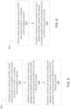
- FIG. 6 is a flow diagram of a process 600 for operating a gateway user plane computing system, in accordance with various embodiments.
- the process 600 may be discussed below with reference to the network controller 100, the wireless communication network 150, the SGW-C 152 and the PGW-C 154.
- operations of the process 600 may be described as performed by a "gateway user plane computing system," which may include the SGW-U 122 or the PGW-U 124, but the process 600 may be performed by any suitably configured device (e.g., a programmed processing system, an ASIC, or another wireless computing device).
- the gateway user plane computing system may perform SGW user plane functions or PGW user plane functions.
- the gateway user plane computing system may include the SGW-U 122 and may perform SGW user plane functions at 602.
- the gateway user plane computing system may include the PGW-U 124 and may perform PGW user plane functions at 602.
- the gateway user plane computing system may be configured to virtualize the SGW user plane functions or the PGW user plane functions in one or more computing devices. For example, in embodiments in which the gateway user plane computing system includes the SGW-U 122, the gateway user plane computing system may virtualize the SGW user plane functions. In embodiments in which the gateway user plane computing system includes the PGW-U 124, the gateway user plane computing system may virtualize the PGW user plane functions.
- the gateway user plane computing system may establish a secure communication link with the network controller 100.
- the network controller 100 may be different from the gateway user plane computing system.
- the network controller 100 may include SGW control plane circuitry that performs control plane functions of an SGW or PGW control plane circuitry that performs control plane functions of a PGW.
- the SGW control plane circuitry may be the SGW control plane circuitry 102.
- the PGW control plane circuitry may be the PGW control plane circuitry 104.
- the secure communication link of 604 may be configured for exchange of control messages between the gateway user plane computing system and the SGW control plane circuitry or the PGW control plane circuitry.
- communication circuitry included in the gateway user plane computing system may establish the secure communication link at 604.
- the communication circuitry 142 may establish the secure communication link at 604.
- the communication circuitry 144 may establish a secure communication link at 604.
- the network controller 100 and the gateway user piane computing system may communicate via the secure communication link to perform various PGW- and/or SGW-related wireless communication operations.
- the process 600 may then end.
- FIGS. 7-9 are signal diagrams of various embodiments of processes for UE attachment.
- attachment may refer to the process of registering a UE with the wireless communication network 150 so that the UE may receive wireless communication services (that require registration) from the network 150.
- FIGS. 7-9 are signal diagrams of processes for UE attachment in embodiments of the wireless communication network 150 in which user plane and control plane functions of the SGW and/or the PGW are separated (e.g., into the SGW C 152/SGW-U 122 and/or the PGW-C 154/PGW-U 124), as discussed above.
- Each of the signal diagrams of FIGS. 7-9 may begin with a Stage 1 Attach Procedure, discussed below.
- the Stage 1 Attach Procedure is illustrated as performed between the UE 164 and the network controller 100 of the wireless communication network 150 of FIG. 4 .
- the Stage 1 Attach Procedure is illustrated as performed between the UE 164 and the MME 160 of the network controller 100 of the wireless communication network 150 of FIG. 4 .
- the Stage 1 Attach Procedure may be performed in accordance with steps 1-11 of ⁇ 5.3.2 of 3GPP Technical Specification 23.401.
- the Stage 1 Attach Procedure may include the following signal flows:
- the network controller 100 may transmit an update message to the SGW-U 122 to update the GTP-U tunnel endpoint identifier (TEID) assigned to the SGW-U 122.
- the network controller 100 may thus assign the TEID to the SGW-U 122.
- the SGW-U 122 may then send the IP address of the SGW-U 122 to the network controller 100.
- the network controller 100 may include the MME 160, the SGW-C 152, and the PGW-C 154.
- the network controller 100 may be implemented as a cloud computing service. For ease of illustration, not all of the information included in a particular message is illustrated in the signal flow diagrams of FIGS. 7-10 .
- "send" messages may include additional information such as the network node address, a bearer identifier, a bearer quality of service, or any other conventional information.
- the network controller 100 may then transmit an update message to the PGW- U 124 to provide the GTP-U TEID of the SGW-U 122 to the PGW-U 124, and to update the GTP-U TEID assigned to the PGW-U 124.
- the network controller 100 may thus assign the TEID to the PGW-U 124.
- the PGW-U 124 may then send the IP address of the PGW-U 124 to the network controller 100.
- the network controller 100 may then transmit an update message to the SGW- U 122 to provide the GTP-U TEID of the PGW-U 124 to the SGW-U 122.
- the SGW- U 122 may use the GTP-U TEID of the PGW-U 124
- the PGW-U 124 may use the GTP-U TEID of the SGW-U 122, to establish a GTP-U tunnel between the SGW-U 122 and the PGW-U 124.
- the network controller 100 may then accept the attachment and send the GTP-U TEID of the SGW-U 122 to the AN 166 (which may be, for example, an eNodeB).
- the AN 166 may send the GTP-U TEID of the AN 166 to the network controller 100.
- the network controller 100 may then send the GTP-U TEID of the AN 166 to the SGW-U 122.
- the SGW-U 122 may use the GTP-U TEID of the AN 166, and the AN 166 may use the GTP-U TEID of the SGW-U 122, to establish a GTP-U tunnel between the SGW-U 122 and the AN 166.
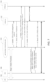
- the MME 160 may transmit a Create Session Request to the SGW-C 152, including the GTP-C TEID of the MME 160.
- the SGW-C 152 may then send a message to the SGW-U 122 to request the GTP-U TEID of the SGW-U 122.
- the SGW-U 122 may respond by sending the GTP-U TEID of the SGW-U 122 to the SGW-C 152.
- the SGW-U 122 may act as a forwarding node, and may create a local GTP-U TEID for itself.
- the SGW-C 152 may then send a Create Session Request message, including the GTP-C TEID of the SGW-C 152 and the GTP-U TEID of the SGW-U 122, to the PGW-C 154.
- the PGW-C 154 may then send a message to the PGW-U 124 to request the GTP-U TEID of the PGW-U 124.
- the PGW-U 124 may respond by sending the GTP- U TEID of the PGW-U 124 to the PGW-C 154.
- the PGW-U 124 may act as a forwarding node, and may create a local GTP-U TEID for itself.
- the PGW-C 154 may then provide the GTP-C TEID of the PGW-C 154 and the GTP-U TEID of the PGW-U 124 to the SGW-C 152.
- the SGW-C 152 may then provide the updated GTP-U TEID of the PGW-U 124 to the SGW-U 122.
- the SGW-C 152 may use the GTP-C TEID of the PGW-C 154, and the PGW-C 154 may use the GTP-C TEID of the SGW-C 152, to establish a GTP-C tunnel between the SGW-C 152 and the PGW- C 154.
- the SGW-U 122 may use the GTP-U TEI D of the PGW-U 124, and the PGW- U 124 may use the GTP-U TEID of the SGW-U 122, to establish a GTP-U tunnel between the SGW-U 122 and the PGW-U 124.
- the SGW-C 152 may then respond to the Create Session Request from the MME 160 with the GTP-C TEID of the SGW-C 152 and the GTP-U TEID of the SGW- U 122.
- the SGW-C 152 may use the GTP-C TEID of the MME 160, and the MME 160 may use the GTP-C TEID of the SGW-C 152, to establish a GTP-C tunnel between the SGW-C 152 and the MME 160.
- the MME 160 may then accept the attachment and send the GTP-U TEID of the SGW-U 122 to the AN 166 (which may be, for example, an eNodeB).
- the AN 166 may send the GTP-U TEID of the AN 166 to the MME 160.
- the MME 160 may then send a Modify Bearer Request message, including the GTP-U TEID of the AN 166, to the SGW-C 152.
- the SGW-C 152 may provide the GTP-U TEID of the AN 166 to the SGW-U 122.
- the SGW-U 122 and the SGW-C 152 may respond to the Modify Bearer Request.
- the SGW-U 122 may use the GTP-U TEID of the AN 166, and the AN 166 may use the GTP-U TEID of the SGW-U 122, to establish a GTP-U tunnel between the SGW- U 122 and the AN 166.
- a single SGW-C 152 may control multiple SGW- Us (as discussed above with reference to FIG. 1 ).
- the SGW-C 152 may be configured to differentiate between the different SGW-Us based on the IP address of the SGW-Us (which may be assigned to the SGW-U hardware by the manufacturer, and may be static over the lifetime of the SGW-U).
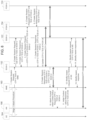
- FIG. 9 a signal flow as illustrated in which the SGW-C 152 and the PGW-C 154 are responsible for GTP tunnel creation (in contrast to the signal flow of FIG. 8 ) and also for updating the SGW-U 122 and the PGW-U 152.
- the MME 160 may transmit a Create Session Request to the SGW- C 152, including the GTP-C TEID of the MME 160.
- the SGW-C 152 may then send a message to the PGW-C 154 with the GTP-C TEID of the SGW-C 152 and the GTP-U TEID of the SGW-U 122.
- the SGW-C 152 may also provide the GTP-U TEID of the SGW-U 122 to the SGW-U 122, thereby assigning the GTP-U TEID to the SGW-U 122.
- the PGW-C 154 may provide the GTP-U TEID of the SGW-U 122 and the GTP-U TEID of the PGW-U 124 to the PGW-U 124 (thereby assigning the GTP-U TEID to the PGW-U 124).
- the PGW-C 154 may provide the GTP-C TEID of the PGW-C 154 and the GTP-U TEID of the PGW-U 124 to the SGW- C 152.
- the SGW-C 152 may then provide the GTP-U TEID of the PGW-U 124 to the SGW-U 122.
- the SGW-C 152 may use the GTP-C TEID of the PGW-C 154, and the PGW-C 154 may use the GTP-C TEID of the SGW-C 152, to establish a GTP-C tunnel between the SGW-C 152 and the PGW-C 154.
- the SGW-U 122 may use the GTP-U TEID of the PGW-U 124, and the PGW-U 124 may use the GTP-U TEID of the SGW- U 122, to establish a GTP-U tunnel between the SGW-U 122 and the PGW-U 124.
- the SGW-C 152 may then respond to the Create Session Request from the MME 160 with the GTP-C TEID of the SGW-C 152 and the GTP-U TEID of the SGW- U 122.
- the SGW-C 152 may use the GTP-C TEID of the MME 160, and the MME 160 may use the GTP-C TEID of the SGW-C 152, to establish a GTP-C tunnel between the SGW-C 152 and the MME 160.
- the MME 160 may then accept the attachment and send the GTP-U TEID of the SGW-U 122 to the AN 166 (which may be, for example, an eNodeB).
- the AN 166 may send the GTP-U TEID of the AN 166 to the MME 160.
- the MME 160 may then send a Modify Bearer Request message, including the GTP-U TEID of the AN 166, to the SGW-C 152.
- the SGW-C 152 may provide the GTP-U TEID of the AN 166 to the SGW-U 122, and may respond to the Modify Bearer Request.
- the SGW-U 122 may use the GTP-U TEID of the AN 166, and the AN 166 may use the GTP-U TEID of the SGW- U 122, to establish a GTP-U tunnel between the SGW-U 122 and the AN 166.
- the signal flows of FIG. 8 and 9 provide two different approaches to distribute them responsibility for GTP tunnel creation among various entities in a wireless communication network.
- the signal flow of FIG. 8 may be more suitable when more responsibility is desired to be allocated to the user plane (e.g., to the SGW-U 122 and the PGW-U 124), while the signal flow FIG. 9 may be more suitable when more responsibility is desired to be allocated to the control plane (e.g., to the SGW-C 152 and the PGW-C 154).
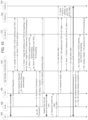
- FIG. 10 is a signal diagram of a process for UE handover, in accordance with various embodiments.
- "handover" may refer to the process by which an AN may transfer service of a UE to another AN.
- the signal flow of FIG. 10 will be discussed with reference to the handover of the UE 164 from the AN 166 (referred to as the "source” AN or “S-AN”)) to the AN 168 (referred to as the "target” AN, or “T-AN”).
- the AN 166 and the AN 168 may be eNodeBs.
- the signal diagram of FIG. 10 may begin when the decision is made to relocate the UE 164 from the S-AN 166 to the T-AN 168. This decision may be made by the S-AN 166.
- the S-AN 166 may send a Handover Required message to the network controller 100 (e.g., the MME 160).
- the Handover Required message may take the form of a conventional LTE Handover Required message, and the format of the Handover Required message is not discussed in further detail herein.
- the network controller 100 may then send an update message to the T-SGW- U 120, providing the TEID of the S-SGW-U 122, and an address and a TEID of the PGW- U 124.
- the T-SGW-U 120 may provide an address of the T-SGW-U 120 to the network controller 100.
- the network controller 100 may then send a Handover Request message to the T-AN 168, which may respond with a Handover Request Acknowledge message.
- the Handover Request and Acknowledge messages may take the form of conventional LTE Handover Request and Acknowledge messages, and are not discussed in further detail herein.
- the network controller 100 may send an address of the T-AN 168 to the T-SGW-U 120 for forwarding, along with the TEID of the T-AN 168.
- the T-SGW- U 120 may send an address of the T-SGW-U 120 for forwarding, along with the TEID of the T-SGW-U 120.
- the network controller 100 may send an address of the T-SGW-U 120 to the S-SGW-U 122 for forwarding, along with the TEID of the T-SGW-U 120.
- the S-SGW-U 122 may send an address of the S-SGW-U 122 for forwarding, along with the TEID of the S-SGW-U 122.
- the network controller 100 may then send a Handover Command to the SAN 166, which may be followed by a Handover Command sent by the S-AN 166 to the UE 164.
- the Handover Commands may take the form of conventional LTE Handover Commands, and are not discussed in further detail herein.
- the S-AN 166 may respond by sending an AN Status Transfer message to the network controller 100.
- a communication pathway from the S-AN 166 to the S-SGW-U 122 and to the T-SGW- U 120, and the communication pathway from the T-SGW-U 120 to the T-AN 168 may be used for indirect forwarding of data. Indirect forwarding of data may be useful when, for example, a direct forwarding path enabled by X2 connectivity between the S-AN 166 and the T-AN 168 is not available.
- the UE 164 may then detach from the old cell (covered by the S-AN 166) and may synchronize with the new cell (covered by the T-AN 168). The UE 164 may then send a Handover Confirm message to the T-AN 168, and may receive downlink data from the T-AN 168. The UE 164 may provide uplink user plane data to the T-AN 168 for transmission to the PGW-U 124.
- the T-AN 168 may send a Handover Notify message to the network controller 100, which may respond by sending an address of the T-AN 168 to the T-SGW- U 120 for downlink data, along with the TEID of the T-AN 168.
- the T-SGW-U 120 may then send an address of the T-SGW-U 120 to the PGW-U 124 for downlink data, along with the TEID of the T-SGW-U 120.
- the T-SGW-U 120 may then send the address of the T-SGW-U 120 to the network controller 104 uplink data, along with the TEID of the T-SGW-U 120.
- the PGW-U 124 may provide downlink user plane data to the T-SGW- U 120 for transmission to the T-AN 168 and, subsequently, to the UE 164.
- a tracking area update procedure may then be performed between the UE 164 and the PGW-U 124.
- the tracking area update procedure may take the form of a conventional LTE tracking area update procedure, and is not discussed in further detail herein.
- the network controller 100 may then transmit a UE context release command to the S-AN 166, which may respond with a UE content release complete message.
- the network controller 100 may then transmit an update message to the S-SGW-U 122, instructing the S-SGW-U 122 to delete the address of the T-SGW-U for forwarding, as well as the associated TEI Ds.
- the network controller 100 may also transmit an update message to the T-SGW-U 120, instructing the T-SGW-U 120 to delete the address of the T-AN 168 for forwarding, as well as the associated TEIDs.
- FIG. 11 is a block diagram of an example computing device 1100, which may be suitable for practicing various disclosed embodiments.
- the computing device 1100 may serve as the SGW-C 152, the PGW-C 154, the SGW-U 122, the PGW-U 124, or any other suitable computing system discussed herein. Any of the circuitry disclosed herein may be implemented by suitable combinations of the hardware discussed below with reference to the computing device 1100 (e.g., programmed memory coupled with one or more processing devices).
- the SGW-C 152, the PGW-C 154, the SGW-U 122, and/or the PGW-U 124 may include multiple ones of the computing device 1100, communicatively coupled to each other.
- the computing device 1100 may include a number of components, including one or more processor(s) 1104 and at least one communication chip 1106.
- the processor 1104 may include a processor core.
- at least one communication chip 1106 may also be physically and electrically coupled to the processor 1104.
- the communication chip 1106 may be part of the processor 1104.
- the computing device 1100 may include a printed circuit board (PCS) 1102.
- PCS printed circuit board
- the processor 1104 and the communication chip 1106 may be disposed thereon.
- the various components may be coupled without the employment of the PCB 1102.
- the computing device 1100 may include other components that may or may not be physically and electrically coupled to the PCB 1102. These other components include, but are not limited to, volatile memory (e.g., dynamic random access memory (DRAM) 1108), non-volatile memory (e.g., read-only memory (ROM) 1110, one or more hard disk drives, one or more solid-state drives, one or more compact disc drives, and/or one or more digital versatile disc drives), flash memory 1112, input/output controller 1114, a digital signal processor (not shown), a crypto processor (not shown), graphics processor 1116, one or more antenna 1118, touch screen display 1120, touch screen controller 1122, other displays (such as liquid-crystal displays, cathode-ray tube displays and e-ink displays, not shown), battery 1124, an audio codec (not shown), a video codec (not shown), global positioning system (GPS) device 1128, compass 1130, an accelerometer
- volatile memory e.g., dynamic random access memory (DRAM)
- the processor 1104 may be integrated on the same die with other components to form a System on Chip (SoC). Any components included in the computing device 1100 (e.g., sensors) may be used to perform various control plane or user plane functionalities, as suitable (e.g., in operations related to attachment or handover of a UE).
- SoC System on Chip
- volatile memory e.g., DRAM 1108
- nonvolatile memory e.g., ROM 1110
- flash memory 1112 e.g., NAND 1112
- mass storage device may include programming instructions configured to enable the computing device 1100, in response to execution by the processor(s) 1104, to practice all or selected aspects of the processes described herein (e.g., the control plane or user plane operations).
- one or more of the memory components such as volatile memory (e.g., DRAM 1108), non-volatile memory (e.g., ROM 1110), flash memory 1112, and the mass storage device may be computer readable media that include temporal and/or persistent (e.g., non-transitory) copies of instructions thereon that, in response to execution by the one or more processor(s) 1104, cause the computing device 1100 to practice all or selected aspects of the processes described herein.
- Memory accessible to the computing device 1100 may include one or more storage resources that are physically part of a device on which the computing device 1100 is installed and/or one or more storage resources that is accessible by, but not necessarily a part of, the computing device 1100.
- a storage resource may be accessed by the computing device 1100 over a network via the communications chip 1106. Any one or more of these memory devices may be included in the SGW-C 152, the PGW-C 154, the SGW-U 122, and/or the PGW-U 124.
- the communication chip 1106 may enable wired and/or wireless communications for the transfer of data to and from the computing device 1100.
- wireless and its derivatives may be used to describe circuits, devices, systems, methods, techniques, communication channels, etc., that may communicate data through the use of modulated electromagnetic radiation through a non-solid medium. The term does not imply that the associated devices do not contain any wires, although in some embodiments they might not. Many of the embodiments described herein may be used with WiFi and 3GPP/LTE communication systems, as noted above. However, the communication chips 1106 may implement any of a number of wireless standards or protocols.
- the computing device 1100 may include a plurality of communication chips 1106.
- a first communication chip 1106 may be dedicated to shorter range wireless communications such as Wi-Fi and Bluetooth and a second communication chip 1106 may be dedicated to longer range wireless communications such as GPS, EDGE, GPRS, CDMA, WiMAX, LTE, Ev-DO, and others.
- the computing device 1100 may be a laptop, a netbook, a notebook, an ultrabook, a smartphone, a computing tablet, a personal digital assistant, an ultra mobile PC, a mobile phone, a desktop computer, a server, a printer, a scanner, a monitor, a set-top box, an entertainment control unit (e.g., a gaming console), a digital camera, a portable music player, or a digital video recorder.
- the computing device 1100 may be any other electronic device that processes data.
Landscapes
- Engineering & Computer Science (AREA)
- Computer Networks & Wireless Communication (AREA)
- Signal Processing (AREA)
- Computer Hardware Design (AREA)
- Computer Security & Cryptography (AREA)
- Computing Systems (AREA)
- General Engineering & Computer Science (AREA)
- Mobile Radio Communication Systems (AREA)
- Databases & Information Systems (AREA)
Claims (6)
- Verfahren, das von einer bedienenden Gateway-Steuerebene, SGW-C, durchgeführt wird, zum Einrichten eines GTP-C-Tunnels zu einer Paketdatennetzwerk-Gateway-Steuerebenenfunktion, PGW-C (154), und Einrichten eines GTP-C-Tunnels zu einer Mobilverwaltungsentität, MME (160), wobei das Verfahren Folgendes umfasst:Empfangen einer Sitzungserzeugungsanforderung, die die GTP-C-TEID der MME (160) enthält, von einer MME (160);Übertragen einer Anforderung, eine Tunnelendpunktkennung, TEID, des SGW-U des allgemeinen Paketfunkdienst-Tunnelprotokolls, GTP-U, von Benutzerdaten zu erhalten, an eine bedienende Gateway-Benutzerebene, SGW-U;Empfangen einer Antwort, die die GTP-U-TEID des SGW-U enthält, von der SGW-U;Übertragen einer Sitzungserzeugungsanforderungsnachricht, die die GTP-U-TEID des SGW-U enthält und eine GTP-C-TEID des SGW-C enthält, an die PGW-C (162);Empfangen einer Sitzungserzeugungsantwort, die die GTP-U-TEID einer Paketdatennetzwerk-Gateway-Benutzerebene, PGW-U, und eine GTP-C-TEID der PGW-C enthält, von der PGW-C (154); undÜbertragen der GTP-U-TEID der PGW-U an die SGW-U;Einrichten eines GTP-C-Tunnels zwischen der SGW-C (152) und der PGW-C (154) unter Verwendung der GTP-C-TEID der SGW-C (152) und der GTP-C-TEID der PGW-C (154);Antworten auf die Sitzungserzeugungsanforderung von der MME (160) mit der GTP-C-TEID der SGW-C (152) und der GTP-U-TEID der SGW-U (122);und Einrichten eines GTP-C-Tunnels zwischen der SGW-C (152) und der MME (160) unter Verwendung der GTP-C-TEID der MME (160) und der GTP-C-TEID der SGW-C.
- Verfahren nach Anspruch 1, wobei die Anforderung der GTP-TEID der SGW-U über eine sichere Kommunikationsverbindung an die SGW-U übertragen wird.
- Vorrichtung, die einen Prozessor umfasst, der konfiguriert ist, um eine bedienende Gateway-Steuerebene, SGW-C, zu veranlassen, ein Verfahren nach Anspruch 1 oder Anspruch 2 zu implementieren.
- Verfahren, das von einer bedienenden Gateway-Benutzerebene, SGW-U, durchgeführt wird, zum Einrichten eines GTP-U-Tunnels zu einer Paketdatennetzwerk-Gateway-Benutzerebene, PGW-U (124), wobei das Verfahren Folgendes umfasst:Empfangen einer Anforderung, eine Tunnelendpunktkennung, TEID, des SGW-U des allgemeinen Paketfunkdienst-Tunnelprotokolls, GTP-U, von Benutzerdaten zu erhalten, von einer bedienenden Gateway-Steuerebene, SGW-C;Erzeugen der GTP-U-TEID des SGW-U-Systems;Übertragen einer Antwort, die die GTP-U-TEID des SGW-U-Systems enthält, an die SGW-C;Empfangen der GTP-U-TEID der PGW-U von der SGW-C; undEinrichten eines GTP-U-Tunnels zwischen der SGW-U und der PGW-U unter Verwendung der GTP-U-TEID der PGW-U (124).
- Verfahren nach Anspruch 4, wobei die Anforderung der GTPTEID des SGW-U-Systems über eine sichere Kommunikationsverbindung von der SGW-C empfangen wird.
- Vorrichtung, die einen Prozessor umfasst, der konfiguriert ist, um eine bedienende Gateway-Benutzerebene, SGW-U, zu veranlassen, ein Verfahren nach Anspruch 4 oder Anspruch 5 zu implementieren.
Applications Claiming Priority (5)
| Application Number | Priority Date | Filing Date | Title |
|---|---|---|---|
| US201361898425P | 2013-10-31 | 2013-10-31 | |
| US201361909938P | 2013-11-27 | 2013-11-27 | |
| US14/513,041 US9596628B2 (en) | 2013-10-31 | 2014-10-13 | Gateway arrangements for wireless communication networks |
| PCT/US2014/060511 WO2015065701A1 (en) | 2013-10-31 | 2014-10-14 | Gateway arrangements for wireless communication networks |
| EP14858618.3A EP3063905A4 (de) | 2013-10-31 | 2014-10-14 | Gateway-anordnungen für drahtloskommunikationsnetzwerke |
Related Parent Applications (1)
| Application Number | Title | Priority Date | Filing Date |
|---|---|---|---|
| EP14858618.3A Division EP3063905A4 (de) | 2013-10-31 | 2014-10-14 | Gateway-anordnungen für drahtloskommunikationsnetzwerke |
Publications (2)
| Publication Number | Publication Date |
|---|---|
| EP4096289A1 EP4096289A1 (de) | 2022-11-30 |
| EP4096289B1 true EP4096289B1 (de) | 2025-02-19 |
Family
ID=52995385
Family Applications (2)
| Application Number | Title | Priority Date | Filing Date |
|---|---|---|---|
| EP14858618.3A Withdrawn EP3063905A4 (de) | 2013-10-31 | 2014-10-14 | Gateway-anordnungen für drahtloskommunikationsnetzwerke |
| EP22184527.4A Active EP4096289B1 (de) | 2013-10-31 | 2014-10-14 | Gateway-anordnungen für drahtloskommunikationsnetzwerke |
Family Applications Before (1)
| Application Number | Title | Priority Date | Filing Date |
|---|---|---|---|
| EP14858618.3A Withdrawn EP3063905A4 (de) | 2013-10-31 | 2014-10-14 | Gateway-anordnungen für drahtloskommunikationsnetzwerke |
Country Status (6)
| Country | Link |
|---|---|
| US (3) | US9596628B2 (de) |
| EP (2) | EP3063905A4 (de) |
| CN (2) | CN105580328A (de) |
| FI (1) | FI4096289T3 (de) |
| HK (2) | HK1224452A1 (de) |
| WO (1) | WO2015065701A1 (de) |
Families Citing this family (56)
| Publication number | Priority date | Publication date | Assignee | Title |
|---|---|---|---|---|
| US9384469B2 (en) * | 2008-09-22 | 2016-07-05 | International Business Machines Corporation | Modifying environmental chat distance based on avatar population density in an area of a virtual world |
| US9215075B1 (en) | 2013-03-15 | 2015-12-15 | Poltorak Technologies Llc | System and method for secure relayed communications from an implantable medical device |
| US9596628B2 (en) * | 2013-10-31 | 2017-03-14 | Intel Corporation | Gateway arrangements for wireless communication networks |
| US10091304B2 (en) * | 2013-12-20 | 2018-10-02 | Nokia Solutions And Networks Gmbh & Co. Kg | SGC and PGC and SGU and PGU allocation procedure |
| CN106464743B (zh) * | 2014-04-11 | 2019-10-01 | 诺基亚通信有限责任两合公司 | 软件定义联网中的多租赁 |
| RU2668114C2 (ru) * | 2014-07-08 | 2018-09-26 | Хуавей Текнолоджиз Ко., Лтд. | Способ управления пользователями совместно используемой сети, соответствующие устройство и система |
| US9678779B2 (en) * | 2014-07-31 | 2017-06-13 | Cavium, Inc. | Method and an apparatus for co-processor data plane virtualization |
| CN105704760B (zh) * | 2014-11-26 | 2019-09-17 | 电信科学技术研究院 | 一种进行数据包传输的方法、设备和系统 |
| US9445279B2 (en) * | 2014-12-05 | 2016-09-13 | Huawei Technologies Co., Ltd. | Systems and methods for placing virtual serving gateways for mobility management |
| EP3232606A4 (de) * | 2015-01-07 | 2017-12-20 | Huawei Technologies Co., Ltd. | Kontrollsignalisierungsübertragungsverfahren in einer mcptt-struktur und zugehörige vorrichtung |
| US10855645B2 (en) | 2015-01-09 | 2020-12-01 | Microsoft Technology Licensing, Llc | EPC node selection using custom service types |
| CN106304371B (zh) * | 2015-05-15 | 2021-07-23 | 中兴通讯股份有限公司 | 一种数据传输方法、装置、终端、基站及系统 |
| WO2016188548A1 (en) * | 2015-05-22 | 2016-12-01 | Huawei Technologies Co., Ltd. | Telecommunication network with automated control and data plane instantiation |
| US9832797B2 (en) | 2015-06-29 | 2017-11-28 | At&T Intellectual Property I, L.P. | Mobility network function consolidation |
| WO2017016615A1 (en) * | 2015-07-30 | 2017-02-02 | Sony Mobile Communications Inc. | Mobile hotspot |
| CN111510986B (zh) * | 2015-09-30 | 2023-06-27 | 华为技术有限公司 | 保持业务连续性的方法、控制面网关和移动管理网元 |
| CN106559917A (zh) * | 2015-09-30 | 2017-04-05 | 中国移动通信集团公司 | 用户设备初始附着方法及系统 |
| US10069791B2 (en) * | 2015-11-02 | 2018-09-04 | Cisco Technology, Inc. | System and method for providing a change in user equipment packet data network internet protocol address in a split control and user plane evolved packet core architecture |
| EP3371942A1 (de) * | 2015-11-06 | 2018-09-12 | Intel IP Corporation | Ressourcenzuweisung auf benutzerebene |
| CN108353023B (zh) | 2015-11-28 | 2021-06-29 | 华为技术有限公司 | 一种信令报文处理方法和实体 |
| US20170163727A1 (en) * | 2015-12-04 | 2017-06-08 | University Of Surrey | A network element system |
| CN106912012B (zh) * | 2015-12-23 | 2019-08-30 | 电信科学技术研究院 | 移动通信网络中的用户面实体的选择方法及控制面实体 |
| EP3913867A1 (de) * | 2016-01-15 | 2021-11-24 | NEC Corporation | Kommunikationssystem und kommunikationsverfahren |
| US11265935B2 (en) * | 2016-01-18 | 2022-03-01 | Samsung Electronics Co., Ltd. | Resource assignment for general packet radio service tunneling protocol (GTP) entities in 5G |
| CN107040674B (zh) * | 2016-02-04 | 2021-04-20 | 华为技术有限公司 | 一种计费方法、装置及系统 |
| JP6431612B2 (ja) * | 2016-02-17 | 2018-11-28 | 株式会社Nttドコモ | ゲートウェイ変更方法 |
| CN107306431A (zh) * | 2016-04-22 | 2017-10-31 | 中兴通讯股份有限公司 | 一种切换的方法、设备和系统 |
| CN107360565B (zh) | 2016-05-09 | 2020-01-07 | 中国移动通信有限公司研究院 | 网关切换方法、控制面网元、网关、基站及网络架构 |
| US10757025B2 (en) | 2016-05-10 | 2020-08-25 | Radcom Ltd. | Smart load balancer and throttle |
| US10050886B2 (en) * | 2016-05-10 | 2018-08-14 | Radcom Ltd. | Load balancing system |
| US11540175B2 (en) | 2016-05-10 | 2022-12-27 | Radcom Ltd. | Smart session load balancer and throttle |
| CN108307402A (zh) * | 2016-08-31 | 2018-07-20 | 中兴通讯股份有限公司 | 管理upf的方法、装置及系统 |
| DE112017004736T5 (de) * | 2016-09-21 | 2019-06-19 | Mavenir Systems, Inc. | Verfahren und System zur Sitzungs-Belastbarkeit in Paket-Gateways |
| CN108307530B (zh) * | 2016-09-30 | 2023-09-22 | 华为技术有限公司 | 一种会话连接建立方法、相关设备及系统 |
| WO2018076184A1 (zh) * | 2016-10-25 | 2018-05-03 | 华为技术有限公司 | 一种用户面选择方法、装置及存储介质 |
| WO2018086674A1 (en) * | 2016-11-08 | 2018-05-17 | Huawei Technologies Co., Ltd. | A network entity for a communication network comprising a control plane and a user plane for providing communication services to a user equipment |
| US10356830B2 (en) * | 2017-01-17 | 2019-07-16 | Cisco Technology, Inc. | System and method to facilitate stateless serving gateway operations in a network environment |
| US20180213540A1 (en) * | 2017-01-25 | 2018-07-26 | Acer Incorporated | Method of mapping data packets and related apparatuses using the same |
| US10779345B2 (en) * | 2017-03-20 | 2020-09-15 | Qualcomm Incorporated | User plane relocation techniques in wireless communication systems |
| CN108737131B (zh) * | 2017-04-14 | 2021-04-20 | 中兴通讯股份有限公司 | 网络设备虚拟化的实现方法和装置 |
| US10548140B2 (en) | 2017-05-02 | 2020-01-28 | Affirmed Networks, Inc. | Flexible load distribution and management in an MME pool |
| EP3619932B1 (de) | 2017-05-05 | 2023-02-22 | Microsoft Technology Licensing, LLC | Verfahren und systeme von auf dienstleistungsfähigkeitsexpositionsfunktion (scef) basierenden internet-der-dinge (iot)-kommunikation |
| US11032378B2 (en) | 2017-05-31 | 2021-06-08 | Microsoft Technology Licensing, Llc | Decoupled control and data plane synchronization for IPSEC geographic redundancy |
| US10856134B2 (en) | 2017-09-19 | 2020-12-01 | Microsoft Technolgy Licensing, LLC | SMS messaging using a service capability exposure function |
| US11051201B2 (en) | 2018-02-20 | 2021-06-29 | Microsoft Technology Licensing, Llc | Dynamic selection of network elements |
| JP7325432B2 (ja) | 2018-03-20 | 2023-08-14 | マイクロソフト テクノロジー ライセンシング,エルエルシー | ネットワークスライシングのシステム及び方法 |
| CN108712328A (zh) * | 2018-04-06 | 2018-10-26 | 长沙开雅电子科技有限公司 | 一种存储虚拟化网关与存储节点间数据传输方法 |
| US11212343B2 (en) | 2018-07-23 | 2021-12-28 | Microsoft Technology Licensing, Llc | System and method for intelligently managing sessions in a mobile network |
| JP6623268B1 (ja) * | 2018-09-26 | 2019-12-18 | ソフトバンク株式会社 | 制御プレーン機器、プログラム、システム及び情報処理装置 |
| EP3878201A4 (de) * | 2018-11-05 | 2022-08-03 | Parallel Wireless, Inc. | Lokal erzeugte teide für hohe kernverfügbarkeit |
| US11095391B2 (en) * | 2018-12-19 | 2021-08-17 | Nxp Usa, Inc. | Secure WiFi communication |
| US11140566B2 (en) * | 2019-04-15 | 2021-10-05 | Netscout Systems, Inc | Matching user and control plane data in a network system using control and user plane separation |
| US11237861B2 (en) | 2019-05-31 | 2022-02-01 | Vmware, Inc. | Managing virtual infrastructure resources in cloud environments |
| JP6827520B2 (ja) * | 2019-12-25 | 2021-02-10 | 華為技術有限公司Huawei Technologies Co.,Ltd. | サービス継続性保証方法、制御プレーンゲートウェイ、およびモビリティ管理ネットワーク要素 |
| US11324077B2 (en) * | 2020-08-20 | 2022-05-03 | Juniper Networks, Inc. | Priority channels for distributed broadband network gateway control packets |
| US12549508B2 (en) * | 2023-02-10 | 2026-02-10 | T-Mobile Usa, Inc. | Increase capacity of a wireless telecommunication network |
Family Cites Families (40)
| Publication number | Priority date | Publication date | Assignee | Title |
|---|---|---|---|---|
| AU2002311554A1 (en) * | 2002-06-25 | 2004-01-06 | Nokia Corporation | Routing method and network element |
| CN101060416B (zh) * | 2006-04-21 | 2010-05-12 | 北京三星通信技术研究有限公司 | 建立和更新隧道传输的方法 |
| CN101325592B (zh) * | 2007-06-14 | 2011-04-20 | 华为技术有限公司 | 一种建立承载连接的方法、装置及系统 |
| CN101816206B (zh) | 2007-10-04 | 2014-10-08 | Lm爱立信电话有限公司 | 针对服务gprs支持节点使用电路交换承载的系统间切换 |
| CN101472314B (zh) * | 2007-11-02 | 2010-05-12 | 华为技术有限公司 | 一种数据处理方法和设备 |
| FI20085193A0 (fi) * | 2008-02-29 | 2008-02-29 | Nokia Siemens Networks Oy | Toistinsolmun yhteydenhallinta |
| CN101459907B (zh) | 2008-03-26 | 2010-09-29 | 中兴通讯股份有限公司 | 一种指示服务网关承载管理的方法 |
| CN101594606B (zh) * | 2008-05-27 | 2012-07-25 | 电信科学技术研究院 | 用户位置信息上报方法、系统及装置 |
| CN101621459B (zh) * | 2008-07-02 | 2011-06-15 | 华为技术有限公司 | 消息传递方法、互通代理节点、数据网关及网络系统 |
| US20100272115A1 (en) | 2009-04-22 | 2010-10-28 | Rajesh Ramankutty | Gateway-based management in a communication network |
| US10893556B2 (en) * | 2009-04-30 | 2021-01-12 | Samsung Electronics Co., Ltd | Method and apparatus for supporting local IP access in a femto cell of a wireless communication system |
| CN101945429B (zh) * | 2009-07-08 | 2014-09-17 | 华为技术有限公司 | 移动网络用户面数据路由的方法、装置和系统 |
| CN101990171B (zh) * | 2009-08-06 | 2013-11-06 | 电信科学技术研究院 | 一种接入节点的接入方法和设备 |
| CN102131259B (zh) * | 2010-01-13 | 2013-06-05 | 华为技术有限公司 | 切换控制方法和相关设备及系统 |
| US9008589B2 (en) | 2010-01-27 | 2015-04-14 | Broadcom Corporation | Wireless bus for intra-chip and inter-chip communication, including wireless-enabled component (WEC) embodiments |
| US8244263B2 (en) | 2010-05-26 | 2012-08-14 | Alcatel Lucent | Primary serving gateway resolution |
| CN102378295B (zh) * | 2010-08-23 | 2016-01-20 | 中兴通讯股份有限公司 | 承载释放方法及系统 |
| US8514756B1 (en) * | 2010-10-15 | 2013-08-20 | Juniper Networks, Inc. | Collectively addressing wireless devices |
| CN102548019B (zh) * | 2010-12-15 | 2016-07-27 | 华为技术有限公司 | 公共路径的建立和使用方法、m2m的通信方法及系统 |
| US8873398B2 (en) | 2011-05-23 | 2014-10-28 | Telefonaktiebolaget L M Ericsson (Publ) | Implementing EPC in a cloud computer with openflow data plane |
| KR102198740B1 (ko) | 2011-07-01 | 2021-01-06 | 인터디지탈 패튼 홀딩스, 인크 | 로컬 ip 액세스 - lipa - 모빌리티를 지원하기 위한 방법 및 장치 |
| CN102892109B (zh) * | 2011-07-21 | 2018-05-11 | 中兴通讯股份有限公司 | 一种实现ip地址属性通知的方法和系统 |
| CN105163398B (zh) * | 2011-11-22 | 2019-01-18 | 华为技术有限公司 | 连接建立方法和用户设备 |
| CN102438330A (zh) * | 2011-12-06 | 2012-05-02 | 大唐移动通信设备有限公司 | 一种附着到e-tran的方法及移动性管理实体 |
| CN103188617B (zh) * | 2011-12-27 | 2016-11-23 | 华为技术有限公司 | 实现集群业务的方法、实体及系统 |
| WO2013127429A1 (en) * | 2012-02-28 | 2013-09-06 | Nokia Siemens Networks Oy | Data forwarding in a mobile communications network system with centralized gateway apparatus controlling distributed gateway elements |
| US9973966B2 (en) * | 2013-01-11 | 2018-05-15 | Interdigital Patent Holdings, Inc. | User-plane congestion management |
| KR101762184B1 (ko) * | 2013-01-31 | 2017-07-27 | 후아웨이 테크놀러지 컴퍼니 리미티드 | 맞춤가능한 이동 광대역 네트워크 시스템 및 이동 광대역 네트워크를 맞춤화하는 방법 |
| US8879551B2 (en) * | 2013-02-22 | 2014-11-04 | International Business Machines Corporation | Collection of subscriber information for data breakout in a mobile data network |
| EP2982079A1 (de) | 2013-04-03 | 2016-02-10 | Nokia Solutions And Networks Management International GmbH | Hochdynamische autorisierung der gleichzeitigen verwendung von getrennten steuerungen |
| WO2014173426A1 (en) * | 2013-04-22 | 2014-10-30 | Nokia Solutions And Networks Oy | Interaction and migration of epc towards virtualized mobile backhaul / sharing of rat (enb, rnc, bsc) |
| EP3005757A1 (de) * | 2013-05-29 | 2016-04-13 | Telefonaktiebolaget LM Ericsson (publ) | Identifikation einer benutzervorrichtung in einem kommunikationsnetz |
| EP3017636B1 (de) * | 2013-07-03 | 2021-08-25 | Nokia Solutions and Networks GmbH & Co. KG | Ruhemoduspufferung auf benutzerebene in einer softwaredefinierten netzwerkarchitektur |
| US9277429B2 (en) * | 2013-08-06 | 2016-03-01 | Cellos Software Ltd. | Monitoring probe for identifying a user plane identifier of a user device |
| WO2015035026A1 (en) * | 2013-09-05 | 2015-03-12 | Mavenir Systems, Inc | Converged media packet gateway for a novel lte data and voice core network architecture |
| US10009264B2 (en) | 2013-09-20 | 2018-06-26 | Nokia Solutions And Networks Gmbh & Co. Kg | Handling of signaling messages on the data plane in a software-defined architecture |
| US9596628B2 (en) * | 2013-10-31 | 2017-03-14 | Intel Corporation | Gateway arrangements for wireless communication networks |
| US10057355B2 (en) | 2014-02-13 | 2018-08-21 | Nec Corporation | Communication system, communication device, communication method, and non-transitory computer readable medium storing program |
| US9491683B2 (en) * | 2014-10-31 | 2016-11-08 | At&T Intellectual Property I, L.P. | Mobile network with software defined networking architecture |
| US10530645B2 (en) * | 2018-06-02 | 2020-01-07 | Verizon Patent And Licensing Inc. | Systems and methods for localized and virtualized radio access networks |
-
2014
- 2014-10-13 US US14/513,041 patent/US9596628B2/en active Active
- 2014-10-14 EP EP14858618.3A patent/EP3063905A4/de not_active Withdrawn
- 2014-10-14 CN CN201480051972.1A patent/CN105580328A/zh active Pending
- 2014-10-14 WO PCT/US2014/060511 patent/WO2015065701A1/en not_active Ceased
- 2014-10-14 CN CN201711112766.9A patent/CN107889176A/zh active Pending
- 2014-10-14 HK HK16112384.1A patent/HK1224452A1/zh unknown
- 2014-10-14 FI FIEP22184527.4T patent/FI4096289T3/fi active
- 2014-10-14 EP EP22184527.4A patent/EP4096289B1/de active Active
-
2017
- 2017-01-27 US US15/418,493 patent/US20170142762A1/en not_active Abandoned
-
2018
- 2018-09-14 HK HK18111846.3A patent/HK1252536A1/zh unknown
-
2022
- 2022-01-13 US US17/575,464 patent/US11917701B2/en active Active
Also Published As
| Publication number | Publication date |
|---|---|
| US11917701B2 (en) | 2024-02-27 |
| EP3063905A4 (de) | 2017-07-12 |
| CN107889176A (zh) | 2018-04-06 |
| US9596628B2 (en) | 2017-03-14 |
| EP3063905A1 (de) | 2016-09-07 |
| FI4096289T3 (fi) | 2025-03-21 |
| CN105580328A (zh) | 2016-05-11 |
| US20150117408A1 (en) | 2015-04-30 |
| WO2015065701A1 (en) | 2015-05-07 |
| US20170142762A1 (en) | 2017-05-18 |
| HK1224452A1 (zh) | 2017-08-18 |
| US20220191955A1 (en) | 2022-06-16 |
| HK1252536A1 (zh) | 2019-05-31 |
| EP4096289A1 (de) | 2022-11-30 |
Similar Documents
| Publication | Publication Date | Title |
|---|---|---|
| US11917701B2 (en) | Gateway arrangements for wireless communication networks | |
| US11375557B2 (en) | Internet protocol (IP) address assignment in integrated access backhaul (IAB) networks | |
| US12543086B2 (en) | Inter-CU migration in IAB network | |
| JP6738908B2 (ja) | 接続がpdnゲートウェイとローカルゲートウェイとの間のデータのルーティングを有効にすることを指示する方法および装置 | |
| US11228560B2 (en) | Mobility functionality for a cloud-based access system | |
| EP3761708B1 (de) | Kommunikationsverfahren und -vorrichtung | |
| US10863560B2 (en) | First network node, receiving network node and methods performed therein | |
| EP3378248B1 (de) | Verfahren und vorrichtungen zur drahtlosen kommunikation mit einem sicherheitsmodell zur unterstützung mehrerer konnektivitäts- und dienstkontexte | |
| CN107637132A (zh) | 用于选择网络分区的方法和装置 | |
| CN108713327A (zh) | 用于实现通信网络中的通信的网络节点和在网络节点中执行的方法 | |
| EP3970342B1 (de) | Funknetzwerknoten und darin durchgeführtes verfahren zur handhabung von kommunikation in einem drahtloskommunikationsnetzwerk | |
| US11419027B2 (en) | User plane link establishment method, base station, and mobility management device | |
| US20220053584A1 (en) | Method for establishing communication bearer, device, and system | |
| WO2022170798A1 (zh) | 确定策略的方法和通信装置 | |
| US20220345889A1 (en) | Security settings for user plane data sent over different accesses of a network | |
| CN116325930A (zh) | 用于拓扑冗余的设备、方法、装置和计算机可读介质 | |
| US20250234415A1 (en) | Methods and apparatuses for management of a data session in home routed session breakout mode | |
| CN118679810A (zh) | 集成接入和回传网络中的服务请求 | |
| CN119545448A (zh) | 一种通信方法和装置 |
Legal Events
| Date | Code | Title | Description |
|---|---|---|---|
| PUAI | Public reference made under article 153(3) epc to a published international application that has entered the european phase |
Free format text: ORIGINAL CODE: 0009012 |
|
| STAA | Information on the status of an ep patent application or granted ep patent |
Free format text: STATUS: REQUEST FOR EXAMINATION WAS MADE |
|
| 17P | Request for examination filed |
Effective date: 20220712 |
|
| AC | Divisional application: reference to earlier application |
Ref document number: 3063905 Country of ref document: EP Kind code of ref document: P |
|
| AK | Designated contracting states |
Kind code of ref document: A1 Designated state(s): AL AT BE BG CH CY CZ DE DK EE ES FI FR GB GR HR HU IE IS IT LI LT LU LV MC MK MT NL NO PL PT RO RS SE SI SK SM TR |
|
| STAA | Information on the status of an ep patent application or granted ep patent |
Free format text: STATUS: EXAMINATION IS IN PROGRESS |
|
| 17Q | First examination report despatched |
Effective date: 20230821 |
|
| GRAP | Despatch of communication of intention to grant a patent |
Free format text: ORIGINAL CODE: EPIDOSNIGR1 |
|
| STAA | Information on the status of an ep patent application or granted ep patent |
Free format text: STATUS: GRANT OF PATENT IS INTENDED |
|
| INTG | Intention to grant announced |
Effective date: 20240911 |
|
| GRAS | Grant fee paid |
Free format text: ORIGINAL CODE: EPIDOSNIGR3 |
|
| GRAA | (expected) grant |
Free format text: ORIGINAL CODE: 0009210 |
|
| STAA | Information on the status of an ep patent application or granted ep patent |
Free format text: STATUS: THE PATENT HAS BEEN GRANTED |
|
| P01 | Opt-out of the competence of the unified patent court (upc) registered |
Free format text: CASE NUMBER: APP_67189/2024 Effective date: 20241219 |
|
| AC | Divisional application: reference to earlier application |
Ref document number: 3063905 Country of ref document: EP Kind code of ref document: P |
|
| AK | Designated contracting states |
Kind code of ref document: B1 Designated state(s): AL AT BE BG CH CY CZ DE DK EE ES FI FR GB GR HR HU IE IS IT LI LT LU LV MC MK MT NL NO PL PT RO RS SE SI SK SM TR |
|
| REG | Reference to a national code |
Ref country code: GB Ref legal event code: FG4D |
|
| REG | Reference to a national code |
Ref country code: CH Ref legal event code: EP |
|
| REG | Reference to a national code |
Ref country code: DE Ref legal event code: R096 Ref document number: 602014091598 Country of ref document: DE |
|
| REG | Reference to a national code |
Ref country code: IE Ref legal event code: FG4D |
|
| REG | Reference to a national code |
Ref country code: FI Ref legal event code: FGE |
|
| REG | Reference to a national code |
Ref country code: SE Ref legal event code: TRGR |
|
| REG | Reference to a national code |
Ref country code: NL Ref legal event code: MP Effective date: 20250219 |
|
| PG25 | Lapsed in a contracting state [announced via postgrant information from national office to epo] |
Ref country code: RS Free format text: LAPSE BECAUSE OF FAILURE TO SUBMIT A TRANSLATION OF THE DESCRIPTION OR TO PAY THE FEE WITHIN THE PRESCRIBED TIME-LIMIT Effective date: 20250519 |
|
| PG25 | Lapsed in a contracting state [announced via postgrant information from national office to epo] |
Ref country code: PL Free format text: LAPSE BECAUSE OF FAILURE TO SUBMIT A TRANSLATION OF THE DESCRIPTION OR TO PAY THE FEE WITHIN THE PRESCRIBED TIME-LIMIT Effective date: 20250219 |
|
| PG25 | Lapsed in a contracting state [announced via postgrant information from national office to epo] |
Ref country code: ES Free format text: LAPSE BECAUSE OF FAILURE TO SUBMIT A TRANSLATION OF THE DESCRIPTION OR TO PAY THE FEE WITHIN THE PRESCRIBED TIME-LIMIT Effective date: 20250219 |
|
| REG | Reference to a national code |
Ref country code: LT Ref legal event code: MG9D |
|
| PG25 | Lapsed in a contracting state [announced via postgrant information from national office to epo] |
Ref country code: IS Free format text: LAPSE BECAUSE OF FAILURE TO SUBMIT A TRANSLATION OF THE DESCRIPTION OR TO PAY THE FEE WITHIN THE PRESCRIBED TIME-LIMIT Effective date: 20250619 Ref country code: NO Free format text: LAPSE BECAUSE OF FAILURE TO SUBMIT A TRANSLATION OF THE DESCRIPTION OR TO PAY THE FEE WITHIN THE PRESCRIBED TIME-LIMIT Effective date: 20250519 |
|
| PG25 | Lapsed in a contracting state [announced via postgrant information from national office to epo] |
Ref country code: NL Free format text: LAPSE BECAUSE OF FAILURE TO SUBMIT A TRANSLATION OF THE DESCRIPTION OR TO PAY THE FEE WITHIN THE PRESCRIBED TIME-LIMIT Effective date: 20250219 |
|
| PG25 | Lapsed in a contracting state [announced via postgrant information from national office to epo] |
Ref country code: HR Free format text: LAPSE BECAUSE OF FAILURE TO SUBMIT A TRANSLATION OF THE DESCRIPTION OR TO PAY THE FEE WITHIN THE PRESCRIBED TIME-LIMIT Effective date: 20250219 |
|
| PG25 | Lapsed in a contracting state [announced via postgrant information from national office to epo] |
Ref country code: PT Free format text: LAPSE BECAUSE OF FAILURE TO SUBMIT A TRANSLATION OF THE DESCRIPTION OR TO PAY THE FEE WITHIN THE PRESCRIBED TIME-LIMIT Effective date: 20250620 Ref country code: LV Free format text: LAPSE BECAUSE OF FAILURE TO SUBMIT A TRANSLATION OF THE DESCRIPTION OR TO PAY THE FEE WITHIN THE PRESCRIBED TIME-LIMIT Effective date: 20250219 |
|
| PG25 | Lapsed in a contracting state [announced via postgrant information from national office to epo] |
Ref country code: BG Free format text: LAPSE BECAUSE OF FAILURE TO SUBMIT A TRANSLATION OF THE DESCRIPTION OR TO PAY THE FEE WITHIN THE PRESCRIBED TIME-LIMIT Effective date: 20250219 Ref country code: GR Free format text: LAPSE BECAUSE OF FAILURE TO SUBMIT A TRANSLATION OF THE DESCRIPTION OR TO PAY THE FEE WITHIN THE PRESCRIBED TIME-LIMIT Effective date: 20250520 |
|
| REG | Reference to a national code |
Ref country code: AT Ref legal event code: MK05 Ref document number: 1769574 Country of ref document: AT Kind code of ref document: T Effective date: 20250219 |
|
| PG25 | Lapsed in a contracting state [announced via postgrant information from national office to epo] |
Ref country code: SM Free format text: LAPSE BECAUSE OF FAILURE TO SUBMIT A TRANSLATION OF THE DESCRIPTION OR TO PAY THE FEE WITHIN THE PRESCRIBED TIME-LIMIT Effective date: 20250219 |
|
| PG25 | Lapsed in a contracting state [announced via postgrant information from national office to epo] |
Ref country code: DK Free format text: LAPSE BECAUSE OF FAILURE TO SUBMIT A TRANSLATION OF THE DESCRIPTION OR TO PAY THE FEE WITHIN THE PRESCRIBED TIME-LIMIT Effective date: 20250219 |
|
| PG25 | Lapsed in a contracting state [announced via postgrant information from national office to epo] |
Ref country code: IT Free format text: LAPSE BECAUSE OF FAILURE TO SUBMIT A TRANSLATION OF THE DESCRIPTION OR TO PAY THE FEE WITHIN THE PRESCRIBED TIME-LIMIT Effective date: 20250219 |
|
| PG25 | Lapsed in a contracting state [announced via postgrant information from national office to epo] |
Ref country code: AT Free format text: LAPSE BECAUSE OF FAILURE TO SUBMIT A TRANSLATION OF THE DESCRIPTION OR TO PAY THE FEE WITHIN THE PRESCRIBED TIME-LIMIT Effective date: 20250219 |
|
| PGFP | Annual fee paid to national office [announced via postgrant information from national office to epo] |
Ref country code: SE Payment date: 20250910 Year of fee payment: 12 |
|
| PG25 | Lapsed in a contracting state [announced via postgrant information from national office to epo] |
Ref country code: EE Free format text: LAPSE BECAUSE OF FAILURE TO SUBMIT A TRANSLATION OF THE DESCRIPTION OR TO PAY THE FEE WITHIN THE PRESCRIBED TIME-LIMIT Effective date: 20250219 Ref country code: CZ Free format text: LAPSE BECAUSE OF FAILURE TO SUBMIT A TRANSLATION OF THE DESCRIPTION OR TO PAY THE FEE WITHIN THE PRESCRIBED TIME-LIMIT Effective date: 20250219 |
|
| PG25 | Lapsed in a contracting state [announced via postgrant information from national office to epo] |
Ref country code: RO Free format text: LAPSE BECAUSE OF FAILURE TO SUBMIT A TRANSLATION OF THE DESCRIPTION OR TO PAY THE FEE WITHIN THE PRESCRIBED TIME-LIMIT Effective date: 20250219 |
|
| PG25 | Lapsed in a contracting state [announced via postgrant information from national office to epo] |
Ref country code: SK Free format text: LAPSE BECAUSE OF FAILURE TO SUBMIT A TRANSLATION OF THE DESCRIPTION OR TO PAY THE FEE WITHIN THE PRESCRIBED TIME-LIMIT Effective date: 20250219 |
|
| REG | Reference to a national code |
Ref country code: DE Ref legal event code: R097 Ref document number: 602014091598 Country of ref document: DE |
|
| PLBE | No opposition filed within time limit |
Free format text: ORIGINAL CODE: 0009261 |
|
| STAA | Information on the status of an ep patent application or granted ep patent |
Free format text: STATUS: NO OPPOSITION FILED WITHIN TIME LIMIT |
|
| PGFP | Annual fee paid to national office [announced via postgrant information from national office to epo] |
Ref country code: DE Payment date: 20250902 Year of fee payment: 12 |
|
| PGFP | Annual fee paid to national office [announced via postgrant information from national office to epo] |
Ref country code: FI Payment date: 20251014 Year of fee payment: 12 |
|
| 26N | No opposition filed |
Effective date: 20251120 |