EP4096209B1 - Informationsverarbeitungsvorrichtung, informationsverarbeitungsverfahren und informationsverarbeitungsprogramm - Google Patents
Informationsverarbeitungsvorrichtung, informationsverarbeitungsverfahren und informationsverarbeitungsprogramm Download PDFInfo
- Publication number
- EP4096209B1 EP4096209B1 EP20915045.7A EP20915045A EP4096209B1 EP 4096209 B1 EP4096209 B1 EP 4096209B1 EP 20915045 A EP20915045 A EP 20915045A EP 4096209 B1 EP4096209 B1 EP 4096209B1
- Authority
- EP
- European Patent Office
- Prior art keywords
- area
- main subject
- information processing
- processing device
- valid data
- Prior art date
- Legal status (The legal status is an assumption and is not a legal conclusion. Google has not performed a legal analysis and makes no representation as to the accuracy of the status listed.)
- Active
Links
Images





Classifications
-
- H—ELECTRICITY
- H04—ELECTRIC COMMUNICATION TECHNIQUE
- H04N—PICTORIAL COMMUNICATION, e.g. TELEVISION
- H04N23/00—Cameras or camera modules comprising electronic image sensors; Control thereof
- H04N23/60—Control of cameras or camera modules
- H04N23/67—Focus control based on electronic image sensor signals
- H04N23/675—Focus control based on electronic image sensor signals comprising setting of focusing regions
-
- G—PHYSICS
- G02—OPTICS
- G02B—OPTICAL ELEMENTS, SYSTEMS OR APPARATUS
- G02B7/00—Mountings, adjusting means, or light-tight connections, for optical elements
- G02B7/28—Systems for automatic generation of focusing signals
- G02B7/36—Systems for automatic generation of focusing signals using image sharpness techniques, e.g. image processing techniques for generating autofocus signals
- G02B7/38—Systems for automatic generation of focusing signals using image sharpness techniques, e.g. image processing techniques for generating autofocus signals measured at different points on the optical axis, e.g. focussing on two or more planes and comparing image data
-
- G—PHYSICS
- G03—PHOTOGRAPHY; CINEMATOGRAPHY; ANALOGOUS TECHNIQUES USING WAVES OTHER THAN OPTICAL WAVES; ELECTROGRAPHY; HOLOGRAPHY
- G03B—APPARATUS OR ARRANGEMENTS FOR TAKING PHOTOGRAPHS OR FOR PROJECTING OR VIEWING THEM; APPARATUS OR ARRANGEMENTS EMPLOYING ANALOGOUS TECHNIQUES USING WAVES OTHER THAN OPTICAL WAVES; ACCESSORIES THEREFOR
- G03B13/00—Viewfinders; Focusing aids for cameras; Means for focusing for cameras; Autofocus systems for cameras
- G03B13/32—Means for focusing
- G03B13/34—Power focusing
- G03B13/36—Autofocus systems
-
- G—PHYSICS
- G06—COMPUTING OR CALCULATING; COUNTING
- G06T—IMAGE DATA PROCESSING OR GENERATION, IN GENERAL
- G06T7/00—Image analysis
- G06T7/20—Analysis of motion
-
- G—PHYSICS
- G06—COMPUTING OR CALCULATING; COUNTING
- G06T—IMAGE DATA PROCESSING OR GENERATION, IN GENERAL
- G06T7/00—Image analysis
- G06T7/60—Analysis of geometric attributes
- G06T7/62—Analysis of geometric attributes of area, perimeter, diameter or volume
-
- G—PHYSICS
- G06—COMPUTING OR CALCULATING; COUNTING
- G06V—IMAGE OR VIDEO RECOGNITION OR UNDERSTANDING
- G06V10/00—Arrangements for image or video recognition or understanding
- G06V10/20—Image preprocessing
- G06V10/25—Determination of region of interest [ROI] or a volume of interest [VOI]
-
- G—PHYSICS
- G06—COMPUTING OR CALCULATING; COUNTING
- G06V—IMAGE OR VIDEO RECOGNITION OR UNDERSTANDING
- G06V10/00—Arrangements for image or video recognition or understanding
- G06V10/70—Arrangements for image or video recognition or understanding using pattern recognition or machine learning
- G06V10/74—Image or video pattern matching; Proximity measures in feature spaces
- G06V10/761—Proximity, similarity or dissimilarity measures
-
- H—ELECTRICITY
- H04—ELECTRIC COMMUNICATION TECHNIQUE
- H04N—PICTORIAL COMMUNICATION, e.g. TELEVISION
- H04N23/00—Cameras or camera modules comprising electronic image sensors; Control thereof
- H04N23/60—Control of cameras or camera modules
- H04N23/61—Control of cameras or camera modules based on recognised objects
-
- G—PHYSICS
- G06—COMPUTING OR CALCULATING; COUNTING
- G06T—IMAGE DATA PROCESSING OR GENERATION, IN GENERAL
- G06T2207/00—Indexing scheme for image analysis or image enhancement
- G06T2207/10—Image acquisition modality
- G06T2207/10028—Range image; Depth image; 3D point clouds
-
- H—ELECTRICITY
- H04—ELECTRIC COMMUNICATION TECHNIQUE
- H04N—PICTORIAL COMMUNICATION, e.g. TELEVISION
- H04N23/00—Cameras or camera modules comprising electronic image sensors; Control thereof
- H04N23/95—Computational photography systems, e.g. light-field imaging systems
- H04N23/958—Computational photography systems, e.g. light-field imaging systems for extended depth of field imaging
- H04N23/959—Computational photography systems, e.g. light-field imaging systems for extended depth of field imaging by adjusting depth of field during image capture, e.g. maximising or setting range based on scene characteristics
Definitions
- the present disclosure relates to an information processing device, an information processing method, and an information processing program.
- Auto Focus (AF) functions for automatically focusing a camera, a camcorder, or the like are often provided in terminals having camera functions, such as mobile phones or smartphones.
- some AF functions are configured so that a user touches, for focusing, on a portion of a subject (hereinafter, referred to as "main subject") that is previewed on a screen of a smartphone or the like and on which the user desires to focus. Meanwhile, when the user does not clearly indicate the main subject to the camera, center-weighted AF that automatically focuses on the subject near the center of the screen is mainly adopted.
- Patent Literature 1 JP 2017-005738 A
- Cited references include WO 2014/109125 A1 disclosing the features of the preamble of claim 1 and JP H03 167539 A .
- the center-weighted AF has a problem that the main subject cannot be appropriately brought into focus, when the main subject is off the center, when nearby and faraway subjects are positioned near the center, or the like.
- the present disclosure proposes an information processing device, an information processing method, and an information processing program that are configured to appropriately bring the main subject into focus.
- the information processing device 10 may be a digital camera or a digital camcorder, or may be a mobile terminal such as a smartphone or tablet personal computer (PC).
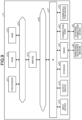
- FIG. 1 is a block diagram illustrating an example of the functional configuration of an information processing device 10 according to the present embodiment.
- the information processing device 10 includes a storage unit 110, an image capture unit 120, a display unit 130, a calculation unit 140, a determination unit 150, a focusing unit 160, a tracking unit 170, a sensor unit 180, and a control unit 200.
- the storage unit 110 is a storage area for temporarily or permanently storing various programs and data.
- the storage unit 110 may store programs and data for performing various functions of the information processing device 10.
- the storage unit 110 may store a program for running a camera application, a learning model for determining a main subject, management data for managing various settings, and the like.
- image capture parameters e.g., various parameters for capturing an image, such as focusing and exposure
- UI user interface
- the image capture unit 120 captures a moving image or picture under control by the control unit 200.
- the image capture unit 120 includes an imaging element, a focus ring, a zoom lens, and the like.
- the moving image or picture captured by the image capture unit 120 are converted into digital data and stored in the storage unit 110.
- the moving image captured by the image capture unit 120 is stored together with voice and environmental sound collected during image capture by a voice input unit (not illustrated) such as a microphone.
- the moving image captured by the image capture unit 120 and stored in the storage unit 110 includes a moving image captured while a recording is made, and a moving image captured, while the recording is not made, for preview of the subject on the display unit 130 or the like.
- the former moving image is displayed on the display unit 130, temporarily stored in a Random Access Memory (RAM), and then stored in a Read Only Memory (ROM).
- RAM Random Access Memory
- ROM Read Only Memory
- the latter moving image is also temporarily stored in the RAM, but when the RAM becomes full, an older moving image is deleted and is not stored in the ROM.
- the display unit 130 displays various visual information under the control by the control unit 200.
- the visual information represents, for example, the UI of the camera application, the subject captured by the image capture unit 120, and the like.
- the display unit 130 includes various display devices such as a Liquid Crystal Display (LCD) device and an Organic Light Emitting Diode (OLED) display device.
- LCD Liquid Crystal Display
- OLED Organic Light Emitting Diode
- the calculation unit 140 calculates, for each predetermined area of an image (captured image) of one frame of the moving image captured by the image capture unit 120, the probability (main subject degree: e.g., 0 to 1) that a subject included in the predetermined area is the main subject.
- the main subject is an object (object) that the camera operator desires to capture.
- a learning model that uses, as training data, a plurality of sets of an image obtained by capturing an object that can be the main subject and a mask image in which a main subject area is masked, one main subject is determined from the captured moving image, and the determined main subject is brought into focus.
- the determination unit 150 determines, as a valid data area, the predetermined area having a main subject degree equal to or larger than a predetermined threshold (e.g., 0.7), and determines one main subject area on the basis of the valid data area.
- a predetermined threshold e.g. 0.
- the tracking unit 170 tracks the main subject determined by the determination unit 150.
- the tracking unit 170 tracks the main subject, and when the main subject is out of the frame or when the main subject degree of the main subject is significantly decreases in the main subject area where the main subject is captured, the determination unit 150 determines another main subject area.
- the sensor unit 180 measures a distance (also referred to as depth or Depth information) to the subject.
- the sensor unit 180 includes, for example, a Time of Flight (ToF) sensor and the like.
- ToF Time of Flight
- the information processing device 10 may include a voice output unit that outputs various sounds and voice, in addition to the above description.
- the voice output unit outputs sound or voice, for example, according to the situation of the camera application under the control by the control unit 200 (e.g., emits sound at the start and end of image capturing).
- the voice output unit includes a speaker and an amplifier.
- the example of the functional configuration of the information processing device 10 according to the present embodiment has been described. Note that the configuration described above with reference to FIG. 1 is merely an example, and the functional configuration of the information processing device 10 according to the present embodiment is not limited to such an example.
- the information processing device 10 may not necessarily include all of the configurations illustrated in FIG. 1 , and each configuration such as the display unit 130 may be included in another device different from the information processing device 10.
- the functional configuration of the information processing device 10 according to the present embodiment can be flexibly modified according to specifications and operations.
- One of the features of the control unit 200 of the information processing device 10 according to the present embodiment is to determine one main subject from the captured moving image by using the learning model, and appropriately focus on the determined main subject.
- the learning model of the present embodiment is a model for identifying a main subject portion in the captured image.
- the learning model includes an input layer to which the captured image (or feature amount of the captured image) is input, an output layer, a first element that belongs to a layer being any of the input layer to the output layer, other than the output layer, and a second element whose value is calculated on the basis of the first element and a weight of the first element.
- the learning model causes the information processing device 10 to function to output, from the output layer, data (e.g., data indicating the main subject degree which is described later) indicating a portion recognized as the main subject in the captured image, according to the captured image (or the feature amount of the captured image) input to the input layer.
- data e.g., data indicating the main subject degree which is described later
- a generation device e.g., the information processing device 10 such as a server device
- the generation device may generate the above-described learning model by using any learning algorithm.
- the generation device may generate the learning model of the present embodiment by using a learning algorithm such as a Neural Network (NN), a Support Vector Machine (SVM), clustering, or reinforcement learning.
- NN Neural Network
- SVM Support Vector Machine
- reinforcement learning it is assumed that the generation device generates the learning model of the present embodiment by using the NN.
- the learning model may have the input layer that includes one or more neurons, an intermediate layer that includes one or more neurons, and the output layer that includes one or more neurons.
- the first element included in the learning model corresponds to input data (x i ) such as x 1 or x 2 .
- the weight of the first element corresponds to a coefficient a i corresponding to x i .
- the regression model can be regarded as a simple perceptron having an input layer and an output layer. When each model is regarded as the simple perceptron, the first element can be regarded to correspond to any node in the input layer, and the second element can be regarded as a node in the output layer.
- the learning model according to the present embodiment is implemented by the NN, such as a Deep Neural Network (DNN), having one or more intermediate layers.
- the first element included in the learning model corresponds to any node included in the input layer or any of the intermediate layers.
- the second element corresponds to a node in the next layer that is a node to which a value is transmitted from a node corresponding to the first element.
- the weight of the first element corresponds to a connection coefficient that is a weight considered for a value transmitted from the node corresponding to the first element to the node corresponding to the second element.
- the main subject degree is calculated using the learning model having any structure such as the regression model or the NN described above. More specifically, in the learning model, the coefficient is set to output the main subject degree for each predetermined area of a captured image when the captured image is input.
- the learning model according to the present embodiment may be a model generated on the basis of a result obtained by repeating input and output of data.
- the learning model according to the present embodiment is a model (referred to as a model X) that outputs the main subject degree for each predetermined area of the captured image when the captured image is input.
- the learning model according to the present embodiment may be a model generated on the basis of a result obtained by repeating input and output of data to and from the model X.
- the learning model according to the present embodiment may be a learning model (referred to as a model Y) in which the captured image is input and the main subject degree output from the model X is output.
- the learning model according to the present embodiment may be a learning model in which the captured image is input and the main subject degree output from the model Y is output.
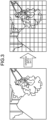
- FIG. 2 is a diagram illustrating an example of extraction of a main subject object according to the present embodiment.
- the left side of FIG. 2 is a captured image of a cat in a living room with a window from which the outside view can be seen.
- the right side of FIG. 2 is an image obtained by extracting the cat that is the main subject.
- the learning model is generated by extracting, from various captured images, objects, such as persons, plants and animals, buildings, moving objects including cars and airplanes, characters and signboards, toys, electrical appliances, food, clothing, accessories, astronomical objects, and the like, that can be the main subject, and being trained to learn images in which the objects that can be the main subjects are captured and the mask images in which the main subject portions are masked.
- Such a learning model makes it possible to determine an appropriate main subject from the captured moving image (image). Furthermore, the depth of the subject that is acquired by the sensor unit 180 may be used as the training data of the learning model. This configuration makes it possible to generate the learning model in consideration of the distance to the subject. Furthermore, it is also possible to perform deep learning by a Recurrent Neural Network (RNN) in which time series data including captured images of past frames of the captured moving image is input.
- RNN Recurrent Neural Network
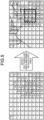
- FIG. 3 is a diagram illustrating an example of segmentation for generating the main subject MAP according to the present embodiment.
- the main subject area is determined by calculating the main subject degree for each predetermined area of the captured image and generating the main subject MAP in which each predetermined area and the main subject degree are mapped.
- each predetermined area is determined, for example, by dividing the captured image into 9 rows ⁇ 11 columns.
- the number of areas to be divided is not limited to 9 rows ⁇ 11 columns, and the number of pixels included in the areas may be constant or different.
- the image may be divided so that the number of pixels included in the respective areas is constant, and pixels corresponding to the number of pixels not included in the areas may be included in areas on the outer edge of the captured image.
- FIG. 4 is a diagram illustrating an example of generation of the main subject MAP according to the present embodiment.
- the main subject degree is calculated for each area of the captured image divided in FIG. 3 , and the main subject MAP is generated.
- the right side of FIG. 4 is an example of the generated main subject MAP.
- the main subject MAP indicates the main subject degree (0 to 1) calculated for each area.
- an area including "flower" in the captured image shows high main subject degree. Note that, in the example of FIG. 4 , the areas having high main subject degree are gathered at one place, but some captured images may have dispersed areas of high main subject degree or have no area of high main subject degree.
- FIG. 5 is a diagram illustrating an example of detection of the rectangular area according to the present embodiment.
- a predetermined area having a main subject degree equal to or larger than the predetermined threshold e.g., 0.7
- the predetermined threshold e.g. 0.
- the adjacent valid data areas are combined and put together into the one valid data area, but are put together into a plurality of valid data areas having different sizes in some cases.
- the valid data area can be determined in a case where the main subject degree of a target area is equal to or larger than the predetermined threshold continuously for a certain period of time (e.g., two seconds).
- the main subject MAPs is generated for each of the captured images of a plurality of frames, and the valid data area is determined by, for example, processing the plurality of main subject MAPs in chronological order.
- the rectangular area inscribed in the valid data area is detected.
- the rectangular area is detected in each of the valid data areas.
- the detected rectangular area is determined as the main subject area.
- a detection condition e.g., upper limit or lower limit
- the width, height, area, and the like of the rectangular area can be further provided for the width, height, area, and the like of the rectangular area. This is because the rectangular area that is too small or too large is not appropriate as the main subject area to be brought into focus.
- one main subject area having the largest area and/or closest to the information processing device 10 is determined from the plurality of main subject areas.
- the distance between the information processing device 10 and each main subject area is measured by the sensor unit 180 such as a ToF sensor to determine the closest main subject area.
- the closest main subject area may be determined by using depth information acquired from a phase-contrast image generated by the image capture unit 120. Then, the determined one main subject area is brought into focus.
- FIG. 6 is a diagram illustrating an example of object tracking according to the present embodiment.
- a bunch of bananas is determined as the main subject by the learning model, and the main subject surrounded by a broken line is tracked by the tracking unit 170.
- the tracking unit 170 continues to track the main subject (the bunch of bananas). Therefore, the main subject is kept in focus.
- the right side of FIG. 6 illustrates that the main subject is kept in focus.
- another main subject area is determined and tracked. Note that, for the loss of the main subject, it can be considered that the main subject is hidden by another object or the main subject degree of the main subject area is significantly reduced. In this case as well, another main subject area is determined. Note that the loss of the main subject can be postponed to a certain degree. For example, instead of determining the another main subject area immediately after the loss of the main subject occurs, the another main subject area can be determined when the loss of the main subject continues for a certain period of time (e.g., three seconds).
- FIG. 7 is a flowchart illustrating the main subject AF process according to the present embodiment.
- the present process is, for example, a process that is triggered by temporarily storing, in the RAM, digital data obtained by converting a moving image obtained by capturing a subject by the image capture unit 120 of the information processing device 10, and that determines the main subject and brings the determined main subject into focus.
- the calculation unit 140 of the information processing device 10 calculates the main subject degree for each predetermined area of an image (captured image) of one frame of the moving image captured by the image capture unit 120 (Step S101).
- the predetermined area is determined by dividing the captured image into a predetermined number of grids (e.g., 9 rows ⁇ 11 columns).
- the determination unit 150 of the information processing device 10 determines, as the valid data area, the predetermined area having a main subject degree equal to or larger than the predetermined threshold, calculated in Step S101 (Step S102). At this time, the valid data area cannot be determined in some cases, since the captured image does not particularly include an object that can be the main subject and there is no area having a main subject degree equal to or larger than the predetermined threshold. In addition, a predetermined number of captured images including past frames can be processed in chronological order to determine, as the valid data area, the predetermined area having a main subject degree equal to or larger than the predetermined threshold continuously for a certain period of time. Therefore, the valid data area including the main subject to be brought into focus can be further appropriately determined.
- Step S103 No
- the process is repeated from Step S101 for an image of the next frame of the captured moving image.
- the captured image does not include the object that can be the main subject, and therefore, it is also possible to bring the center area of the captured image into focus.
- the determination unit 150 detects the rectangular area inscribed in the valid data area and satisfying a predetermined detection condition, and determines the rectangular area as the main subject area (Step S104).
- the rectangular area satisfying the predetermined detection condition is, for example, a rectangular area that has a width equal to or larger than a predetermined width and a height equal to or larger than a predetermined height. Therefore, there may be a plurality of rectangular areas satisfying the detection condition, and a plurality of main subject areas may be determined, in some cases.
- Step S106 When the one main subject area is determined in Step S106, or when one main subject area is determined in Step S104 (Step S105: Yes), the focusing unit 160 of the information processing device 10 focuses on the determined one main subject area (Step S107). After Step S107, the present process ends.
- FIG. 8 is a flowchart illustrating the main subject tracking process according to the present embodiment.
- the present process is a process that is triggered by determination of the main subject area in the main subject AF process of FIG. 7 and that tracks the main subject to be brought into focus.
- the tracking unit 170 determines whether the main subject being tracked is lost (Step S202). Note that it is also possible to process a predetermined number of captured images including past frames in chronological order to determine that the main subject has been lost when the main subject has been lost continuously for a certain period of time.
- Step S203 When the main subject is not lost (Step S203: No), the process returns to Step S201, and the tracking unit 170 tracks the main subject.
- Step S203: Yes the determination unit 150 of the information processing device 10 determines a second valid data area that is different from the valid data area including the main subject having been tracked and that has a main subject degree equal to or larger than the predetermined threshold (Step S204).
- Step S205 When the second valid data area can be determined (Step S205: Yes), the process proceeds to Step S104 in FIG. 7 , a rectangular area inscribed in the second valid data area determined in Step S204 is detected, and the rectangular area is determined as the main subject area. Then, the process proceeds to Step S105.
- FIG. 9 is a block diagram illustrating an example of the hardware configuration of the information processing device 10 according to the present embodiment.
- the information processing device 10 includes, for example, a processor 411, ROM 412, RAM 413, a host bus 414, a bridge 415, an external bus 416, an interface 417, an input device 418, an output device 419, a storage 420, a drive 421, a connection port 422, and a communication device 423.
- the hardware configuration illustrated here is merely an example, and some of the component elements may be omitted. In addition, a component element other than the component elements illustrated in the drawing may be further included.
- the processor 411 functions as an arithmetic processing device or a control device, for example, and controls all or part of the operation of component elements, on the basis of various programs or various data (including the learning model) recorded in the ROM 412, the RAM 413, the storage 420, or a removable recording medium 20.
- the ROM 412 is a unit that stores a program read by the processor 411, data (including the learning model) used for calculation, and the like.
- the RAM 413 temporarily or permanently stores, for example, a program read by the processor 411, various parameters that appropriately change when the program is executed, and the like.
- the processor 411, the ROM 412, and the RAM 413 are mutually connected, for example, via the host bus 414 configured to transmit data at high speed.
- the host bus 414 is connected to, for example, the external bus 416 configured to transmit data at relatively low speed via the bridge 415.
- the external bus 416 is connected to various component elements via the interface 417.
- the input device 418 employs, for example, a mouse, a keyboard, a touch panel, a button, a switch, and a lever. Furthermore, for the input device 418, a remote controller configured to transmit a control signal by using infrared rays or another radio wave is sometimes used. Furthermore, the input device 418 includes a voice sound input device such as a microphone.
- the output device 419 is a device that is configured to visually or audibly notify the user of acquired information, for example, a display device such as a Cathode Ray Tube (CRT), LCD, or organic EL, an audio output device such as a speaker or headphone, a printer, a mobile phone, or a facsimile. Furthermore, the output device 419 according to the present embodiment includes various vibrating devices configured to output tactile stimulation.
- a display device such as a Cathode Ray Tube (CRT), LCD, or organic EL
- an audio output device such as a speaker or headphone, a printer, a mobile phone, or a facsimile.
- the output device 419 according to the present embodiment includes various vibrating devices configured to output tactile stimulation.
- the storage 420 is a device for storing various data.
- the storage 420 employs, for example, a magnetic storage device such as a hard disk drive (HDD), a semiconductor storage device, an optical storage device, a magneto-optical storage device, or the like.
- a magnetic storage device such as a hard disk drive (HDD)
- a semiconductor storage device such as a hard disk drive (HDD)
- an optical storage device such as a magneto-optical storage device, or the like.
- the drive 421 is, for example, a device that reads information recorded on the removable recording medium 20 such as a magnetic disk, optical disk, magneto-optical disk, or semiconductor memory or that writes information to the removable recording medium 20.
- the removable recording medium 20 is, for example, a DVD medium, a Blu-ray (registered trademark) medium, an HD DVD medium, various semiconductor storage media, or the like.
- the removable recording medium 20 may be, for example, an IC card with a noncontact IC chip, an electronic device, or the like.
- connection port 422 is, for example, a Universal Serial Bus (USB) port, an IEEE1394 port, a Small Computer System Interface (SCSI), an RS-232C port, or a port for connecting an external connection device 30 such as optical audio terminal.
- USB Universal Serial Bus
- SCSI Small Computer System Interface
- RS-232C Small Computer System Interface
- the external connection device 30 is, for example, a printer, a portable music player, a digital camera, a digital camcorder, an IC recorder, or the like.
- the communication device 423 is a communication device for connection to a network, and is, for example, a communication card for wired or wireless LAN, Bluetooth (registered trademark), or Wireless USB (WUSB), an optical communication router, an Asymmetric Digital Subscriber Line (ADSL) router, various communication routers, or the like.
- a communication card for wired or wireless LAN Bluetooth (registered trademark), or Wireless USB (WUSB)
- WLAN Wireless USB
- ADSL Asymmetric Digital Subscriber Line
Landscapes
- Engineering & Computer Science (AREA)
- Physics & Mathematics (AREA)
- Multimedia (AREA)
- General Physics & Mathematics (AREA)
- Theoretical Computer Science (AREA)
- Computer Vision & Pattern Recognition (AREA)
- Signal Processing (AREA)
- Health & Medical Sciences (AREA)
- Geometry (AREA)
- Artificial Intelligence (AREA)
- Computing Systems (AREA)
- Databases & Information Systems (AREA)
- Evolutionary Computation (AREA)
- General Health & Medical Sciences (AREA)
- Medical Informatics (AREA)
- Software Systems (AREA)
- Optics & Photonics (AREA)
- Studio Devices (AREA)
- Image Analysis (AREA)
Claims (13)
- Informationsverarbeitungsvorrichtung (10), die einschließt:eine Bildaufnahmeeinheit (120), die ein Bild eines Motivs aufnimmt und das Bild in digitale Daten umwandelt, um ein aufgenommenes Bild zu erzeugen;eine Berechnungseinheit (140), die für jeden vorbestimmten Bereich des aufgenommenen Bildes eine Wahrscheinlichkeit berechnet, dass das im vorbestimmten Bereich eingeschlossene Motiv ein Hauptmotiv ist, das durch einen Kamerabediener aufgenommen werden soll;eine Bestimmungseinheit (150), die den vorbestimmten Bereich, in dem die Wahrscheinlichkeit einen vorbestimmten Schwellenwert überschreitet, als einen gültigen Datenbereich bestimmt und basierend auf dem gültigen Datenbereich einen Hauptmotivbereich bestimmt; undeine Fokussierungseinheit (160), die auf den bestimmten Hauptmotivbereich fokussiert;dadurch gekennzeichnet, dass die Bestimmungseinheit ferner konfiguriert ist, um den gültigen Datenbereich durch Bestimmen des vorbestimmten Bereichs, in dem die Wahrscheinlichkeit den vorbestimmten Schwellenwert für einen gewissen Zeitraum überschreitet, als den gültigen Datenbereich zu bestimmen.
- Informationsverarbeitungsvorrichtung nach Anspruch 1, wobei die Berechnung der Wahrscheinlichkeit durch die Berechnungseinheit unter Verwendung eines Lernmodells durchgeführt wird, wobei das aufgenommene Bild darin eingegeben und die Wahrscheinlichkeit ausgegeben wird.
- Informationsverarbeitungsvorrichtung nach Anspruch 1, wobei
die Bestimmung des Hauptmotivbereichs durch die Bestimmungseinheit einschließt:Kombinieren der benachbarten gültigen Datenbereiche;Erkennen eines rechteckigen Bereichs, der in den erhaltenen gültigen Datenbereich eingeschrieben ist; undBestimmen der rechteckigen Fläche als den Hauptmotivbereich. - Informationsverarbeitungsvorrichtung nach Anspruch 3, wobeidas Bestimmen, durch die Bestimmungseinheit, des rechteckigen Bereichs als den Hauptmotivbereich einschließtdas Bestimmen, als den Hauptmotivbereich, des rechteckigen Bereichs, bei dem mindestens eines einer Breite, einer Höhe und eines Bereichs eine vorbestimmte Bedingung erfüllt.
- Informationsverarbeitungsvorrichtung nach Anspruch 1, wobeiwenn es eine Vielzahl der Hauptmotivbereiche gibt, die durch die Bestimmungseinheit bestimmt werden, die Bestimmungseinheit ferner aus der Vielzahl der Hauptmotivbereiche einen ersten Hauptmotivbereich bestimmt, der mindestens eines von dem größten Bereich und der Informationsverarbeitungsvorrichtung am nächsten erfüllt, undder durch die Fokussierungseinheit in den Fokus gebrachte Hauptmotivbereich der erste Hauptmotivbereich ist.
- Informationsverarbeitungsvorrichtung nach Anspruch 1, die ferner eine Verfolgungseinheit einschließt, die das Hauptmotiv verfolgt, das im bestimmten Hauptmotivbereich eingeschlossen ist.
- Informationsverarbeitungsvorrichtung nach Anspruch 6, wobei, wenn sich das verfolgte Hauptmotiv außerhalb eines Rahmens befindet oder wenn die Wahrscheinlichkeit, dass der Hauptmotivbereich dem verfolgten Hauptmotiv entspricht, für einen gewissen Zeitraum gleich oder kleiner als der vorbestimmte Schwellenwert ist, die Bestimmungseinheit ferner einen zweiten Hauptmotivbereich basierend auf dem gültigen Datenbereich bestimmt.
- Informationsverarbeitungsvorrichtung nach Anspruch 8, wobei, wenn der zweite Hauptmotivbereich nicht bestimmt ist, die Fokussierungseinheit ferner auf einen vorbestimmten Mittenbereich des aufgenommenen Bildes fokussiert.
- Informationsverarbeitungsvorrichtung nach Anspruch 5, die ferner einschließteine Sensoreinheit, welche die Entfernung zum Motiv misst,wobei der durch die Bestimmungseinheit bestimmte nächste erste Hauptmotivbereich basierend auf der gemessenen Entfernung bestimmt wird.
- Informationsverarbeitungsvorrichtung nach Anspruch 5, wobeidie Bildaufnahmeeinheit ferner ein Phasenkontrastbild für das Motiv erzeugt undder durch die Bestimmungseinheit bestimmte nächste erste Hauptmotivbereich basierend auf aus dem Phasenkontrastbild erfassten Tiefeninformationen bestimmt wird.
- Informationsverarbeitungsvorrichtung nach Anspruch 2, wobei eine Entfernung zu einem Motiv, welches das Hauptmotiv sein kann, ferner in das durch die Berechnungseinheit verwendete Lernmodell eingegeben wird.
- Verfahren zum Durchführen,
durch eine Informationsverarbeitungsvorrichtung, eines Prozesses, der einschließt:Aufnehmen eines Bildes eines Motivs und Umwandeln des Bildes in digitale Daten, um ein aufgenommenes Bild zu erzeugen;Berechnen einer Wahrscheinlichkeit für jeden vorbestimmten Bereich des aufgenommenen Bildes, dass das in dem vorbestimmten Bereich eingeschlossene Motiv ein Hauptmotiv ist, das durch einen Kamerabediener aufgenommen werden soll;Bestimmen des vorbestimmten Bereichs, in dem die Wahrscheinlichkeit einen vorbestimmten Schwellenwert überschreitet, als einen gültigen Datenbereich;Bestimmen eines Hauptmotivbereichs basierend auf dem gültigen Datenbereich undFokussieren auf den bestimmten Hauptmotivbereich;dadurch gekennzeichnet, dass die Bestimmung des gültigen Datenbereichs durch die Bestimmungseinheit einschließtdas Bestimmen des vorbestimmten Bereichs, in dem die Wahrscheinlichkeit den vorbestimmten Schwellenwert für einen gewissen Zeitraum überschreitet, als den gültigen Datenbereich. - Programm, das
eine Informationsverarbeitungsvorrichtung zum Durchführen eines Prozesses veranlasst, der einschließt:Aufnehmen eines Bildes eines Motivs und Umwandeln des Bildes in digitale Daten, um ein aufgenommenes Bild zu erzeugen;Berechnen einer Wahrscheinlichkeit für jeden vorbestimmten Bereich des aufgenommenen Bildes, dass das in dem vorbestimmten Bereich eingeschlossene Motiv ein Hauptmotiv ist, das durch einen Kamerabediener aufgenommen werden soll;Bestimmen des vorbestimmten Bereichs, in dem die Wahrscheinlichkeit einen vorbestimmten Schwellenwert überschreitet, als einen gültigen Datenbereich;Bestimmen eines Hauptmotivbereichs basierend auf dem gültigen Datenbereich undFokussieren auf den bestimmten Hauptmotivbereich;dadurch gekennzeichnet, dass die Bestimmung des gültigen Datenbereichs durch die Bestimmungseinheit einschließtdas Bestimmen des vorbestimmten Bereichs, in dem die Wahrscheinlichkeit den vorbestimmten Schwellenwert für einen gewissen Zeitraum überschreitet, als den gültigen Datenbereich.
Applications Claiming Priority (1)
| Application Number | Priority Date | Filing Date | Title |
|---|---|---|---|
| PCT/JP2020/002481 WO2021149238A1 (ja) | 2020-01-24 | 2020-01-24 | 情報処理装置、情報処理方法、および情報処理プログラム |
Publications (3)
| Publication Number | Publication Date |
|---|---|
| EP4096209A1 EP4096209A1 (de) | 2022-11-30 |
| EP4096209A4 EP4096209A4 (de) | 2023-01-18 |
| EP4096209B1 true EP4096209B1 (de) | 2024-09-18 |
Family
ID=76993177
Family Applications (1)
| Application Number | Title | Priority Date | Filing Date |
|---|---|---|---|
| EP20915045.7A Active EP4096209B1 (de) | 2020-01-24 | 2020-01-24 | Informationsverarbeitungsvorrichtung, informationsverarbeitungsverfahren und informationsverarbeitungsprogramm |
Country Status (3)
| Country | Link |
|---|---|
| US (1) | US12244924B2 (de) |
| EP (1) | EP4096209B1 (de) |
| WO (1) | WO2021149238A1 (de) |
Families Citing this family (2)
| Publication number | Priority date | Publication date | Assignee | Title |
|---|---|---|---|---|
| TWI891951B (zh) * | 2021-01-06 | 2025-08-01 | 日商發那科股份有限公司 | 圖像處理裝置 |
| JP2024078297A (ja) * | 2022-11-29 | 2024-06-10 | キヤノン株式会社 | 撮像装置及びその制御方法 |
Family Cites Families (15)
| Publication number | Priority date | Publication date | Assignee | Title |
|---|---|---|---|---|
| JP3217052B2 (ja) | 1989-11-27 | 2001-10-09 | オリンパス光学工業株式会社 | カメラの焦点検出装置 |
| US5227830A (en) | 1989-11-27 | 1993-07-13 | Olympus Optical Co., Ltd. | Automatic camera |
| JP2008035125A (ja) | 2006-07-27 | 2008-02-14 | Canon Inc | 撮像装置、画像処理方法およびプログラム |
| JP4732397B2 (ja) | 2007-04-11 | 2011-07-27 | 富士フイルム株式会社 | 撮像装置及びその合焦制御方法 |
| JP2010087599A (ja) * | 2008-09-29 | 2010-04-15 | Fujifilm Corp | 撮像装置、方法およびプログラム |
| JP4995175B2 (ja) | 2008-10-29 | 2012-08-08 | 富士フイルム株式会社 | 立体撮像装置及び合焦制御方法 |
| JP2015097301A (ja) * | 2012-03-09 | 2015-05-21 | ソニー株式会社 | 画像処理装置、画像処理方法、プログラム |
| JP2014119725A (ja) | 2012-12-19 | 2014-06-30 | Casio Comput Co Ltd | 露出、焦点制御装置、方法、およびプログラム |
| EP2945366B1 (de) | 2013-01-09 | 2019-10-16 | Sony Corporation | Bildverarbeitungsvorrichtung, bildverarbeitungsverfahren und programm |
| US9196027B2 (en) * | 2014-03-31 | 2015-11-24 | International Business Machines Corporation | Automatic focus stacking of captured images |
| JP6338429B2 (ja) | 2014-04-15 | 2018-06-06 | キヤノン株式会社 | 被写体検出装置、被写体検出方法及びプログラム |
| JP6577703B2 (ja) | 2014-08-05 | 2019-09-18 | キヤノン株式会社 | 画像処理装置及び画像処理方法、プログラム、記憶媒体 |
| JP6274272B2 (ja) | 2016-08-03 | 2018-02-07 | ソニー株式会社 | 画像処理装置、画像処理方法、プログラム |
| JP6833505B2 (ja) * | 2016-12-27 | 2021-02-24 | キヤノン株式会社 | 撮像制御装置及びその制御方法 |
| JP7525990B2 (ja) * | 2019-10-29 | 2024-07-31 | キヤノン株式会社 | 主被写体判定装置、撮像装置、主被写体判定方法、及びプログラム |
-
2020
- 2020-01-24 EP EP20915045.7A patent/EP4096209B1/de active Active
- 2020-01-24 US US17/758,916 patent/US12244924B2/en active Active
- 2020-01-24 WO PCT/JP2020/002481 patent/WO2021149238A1/ja not_active Ceased
Also Published As
| Publication number | Publication date |
|---|---|
| EP4096209A1 (de) | 2022-11-30 |
| US12244924B2 (en) | 2025-03-04 |
| WO2021149238A1 (ja) | 2021-07-29 |
| EP4096209A4 (de) | 2023-01-18 |
| US20230128043A1 (en) | 2023-04-27 |
Similar Documents
| Publication | Publication Date | Title |
|---|---|---|
| JP6911866B2 (ja) | 情報処理装置および情報処理方法 | |
| EP3792818B1 (de) | Videoverarbeitungsverfahren und -vorrichtung sowie speichermedium | |
| US10134165B2 (en) | Image distractor detection and processing | |
| WO2019137167A1 (zh) | 相册管理方法、装置、存储介质及电子设备 | |
| CN111984821B (zh) | 确定视频动态封面的方法、装置、存储介质及电子设备 | |
| WO2020194497A1 (ja) | 情報処理装置、個人識別装置、情報処理方法及び記憶媒体 | |
| CN107871000B (zh) | 音频播放方法、装置、存储介质及电子设备 | |
| KR102198337B1 (ko) | 전자 장치, 전자 장치의 제어 방법 및 컴퓨터 판독 매체. | |
| CN107871001B (zh) | 音频播放方法、装置、存储介质及电子设备 | |
| US20180336435A1 (en) | Apparatus and method for classifying supervisory data for machine learning | |
| US10937428B2 (en) | Pose-invariant visual speech recognition using a single view input | |
| EP4096209B1 (de) | Informationsverarbeitungsvorrichtung, informationsverarbeitungsverfahren und informationsverarbeitungsprogramm | |
| EP4145386A1 (de) | Informationsverarbeitungsvorrichtung und -programm | |
| US11620997B2 (en) | Information processing device and information processing method | |
| CN111126372B (zh) | 视频中logo区域的标记方法、装置及电子设备 | |
| US12518534B2 (en) | Analysis system and control method for analysis system | |
| CN111539390A (zh) | 一种基于Yolov3的小目标图像识别方法、设备和系统 | |
| JP7084962B2 (ja) | 推定プログラム、推定装置、推定方法、生成プログラム、生成装置及び生成方法 | |
| CN111062337B (zh) | 人流方向检测方法及装置、存储介质和电子设备 | |
| US12462560B2 (en) | Video manipulation detection | |
| US11893980B2 (en) | Electronic apparatus and control method thereof | |
| US11887457B2 (en) | Information processing device, method, and program | |
| CN113283345A (zh) | 板书书写行为检测方法、训练方法、装置、介质及设备 | |
| CN115294583B (zh) | 基于ocr和nlp的软件内容分析方法、装置、存储介质 | |
| KR20220018805A (ko) | 화재 감지 장치 및 화재 감지 방법 |
Legal Events
| Date | Code | Title | Description |
|---|---|---|---|
| STAA | Information on the status of an ep patent application or granted ep patent |
Free format text: STATUS: THE INTERNATIONAL PUBLICATION HAS BEEN MADE |
|
| PUAI | Public reference made under article 153(3) epc to a published international application that has entered the european phase |
Free format text: ORIGINAL CODE: 0009012 |
|
| STAA | Information on the status of an ep patent application or granted ep patent |
Free format text: STATUS: REQUEST FOR EXAMINATION WAS MADE |
|
| 17P | Request for examination filed |
Effective date: 20220803 |
|
| AK | Designated contracting states |
Kind code of ref document: A1 Designated state(s): AL AT BE BG CH CY CZ DE DK EE ES FI FR GB GR HR HU IE IS IT LI LT LU LV MC MK MT NL NO PL PT RO RS SE SI SK SM TR |
|
| A4 | Supplementary search report drawn up and despatched |
Effective date: 20221215 |
|
| RIC1 | Information provided on ipc code assigned before grant |
Ipc: G03B 15/00 20210101ALI20221209BHEP Ipc: G03B 13/36 20210101ALI20221209BHEP Ipc: G02B 7/28 20210101ALI20221209BHEP Ipc: H04N 5/232 20060101AFI20221209BHEP |
|
| DAV | Request for validation of the european patent (deleted) | ||
| DAX | Request for extension of the european patent (deleted) | ||
| REG | Reference to a national code |
Ref country code: DE Ref legal event code: R079 Free format text: PREVIOUS MAIN CLASS: H04N0005232000 Ref country code: DE Ref legal event code: R079 Ref document number: 602020038151 Country of ref document: DE Free format text: PREVIOUS MAIN CLASS: H04N0005232000 Ipc: H04N0023610000 |
|
| GRAP | Despatch of communication of intention to grant a patent |
Free format text: ORIGINAL CODE: EPIDOSNIGR1 |
|
| STAA | Information on the status of an ep patent application or granted ep patent |
Free format text: STATUS: GRANT OF PATENT IS INTENDED |
|
| RIC1 | Information provided on ipc code assigned before grant |
Ipc: H04N 23/67 20230101ALI20240408BHEP Ipc: H04N 23/61 20230101AFI20240408BHEP |
|
| INTG | Intention to grant announced |
Effective date: 20240425 |
|
| GRAS | Grant fee paid |
Free format text: ORIGINAL CODE: EPIDOSNIGR3 |
|
| GRAA | (expected) grant |
Free format text: ORIGINAL CODE: 0009210 |
|
| STAA | Information on the status of an ep patent application or granted ep patent |
Free format text: STATUS: THE PATENT HAS BEEN GRANTED |
|
| P01 | Opt-out of the competence of the unified patent court (upc) registered |
Free format text: CASE NUMBER: APP_45413/2024 Effective date: 20240806 |
|
| AK | Designated contracting states |
Kind code of ref document: B1 Designated state(s): AL AT BE BG CH CY CZ DE DK EE ES FI FR GB GR HR HU IE IS IT LI LT LU LV MC MK MT NL NO PL PT RO RS SE SI SK SM TR |
|
| REG | Reference to a national code |
Ref country code: GB Ref legal event code: FG4D |
|
| REG | Reference to a national code |
Ref country code: CH Ref legal event code: EP |
|
| REG | Reference to a national code |
Ref country code: IE Ref legal event code: FG4D |
|
| REG | Reference to a national code |
Ref country code: DE Ref legal event code: R096 Ref document number: 602020038151 Country of ref document: DE |
|
| REG | Reference to a national code |
Ref country code: LT Ref legal event code: MG9D |
|
| PG25 | Lapsed in a contracting state [announced via postgrant information from national office to epo] |
Ref country code: NO Free format text: LAPSE BECAUSE OF FAILURE TO SUBMIT A TRANSLATION OF THE DESCRIPTION OR TO PAY THE FEE WITHIN THE PRESCRIBED TIME-LIMIT Effective date: 20241218 |
|
| PG25 | Lapsed in a contracting state [announced via postgrant information from national office to epo] |
Ref country code: GR Free format text: LAPSE BECAUSE OF FAILURE TO SUBMIT A TRANSLATION OF THE DESCRIPTION OR TO PAY THE FEE WITHIN THE PRESCRIBED TIME-LIMIT Effective date: 20241219 Ref country code: FI Free format text: LAPSE BECAUSE OF FAILURE TO SUBMIT A TRANSLATION OF THE DESCRIPTION OR TO PAY THE FEE WITHIN THE PRESCRIBED TIME-LIMIT Effective date: 20240918 |
|
| PG25 | Lapsed in a contracting state [announced via postgrant information from national office to epo] |
Ref country code: BG Free format text: LAPSE BECAUSE OF FAILURE TO SUBMIT A TRANSLATION OF THE DESCRIPTION OR TO PAY THE FEE WITHIN THE PRESCRIBED TIME-LIMIT Effective date: 20240918 |
|
| PG25 | Lapsed in a contracting state [announced via postgrant information from national office to epo] |
Ref country code: LV Free format text: LAPSE BECAUSE OF FAILURE TO SUBMIT A TRANSLATION OF THE DESCRIPTION OR TO PAY THE FEE WITHIN THE PRESCRIBED TIME-LIMIT Effective date: 20240918 |
|
| PG25 | Lapsed in a contracting state [announced via postgrant information from national office to epo] |
Ref country code: HR Free format text: LAPSE BECAUSE OF FAILURE TO SUBMIT A TRANSLATION OF THE DESCRIPTION OR TO PAY THE FEE WITHIN THE PRESCRIBED TIME-LIMIT Effective date: 20240918 |
|
| REG | Reference to a national code |
Ref country code: NL Ref legal event code: MP Effective date: 20240918 |
|
| PG25 | Lapsed in a contracting state [announced via postgrant information from national office to epo] |
Ref country code: RS Free format text: LAPSE BECAUSE OF FAILURE TO SUBMIT A TRANSLATION OF THE DESCRIPTION OR TO PAY THE FEE WITHIN THE PRESCRIBED TIME-LIMIT Effective date: 20241218 |
|
| PG25 | Lapsed in a contracting state [announced via postgrant information from national office to epo] |
Ref country code: RS Free format text: LAPSE BECAUSE OF FAILURE TO SUBMIT A TRANSLATION OF THE DESCRIPTION OR TO PAY THE FEE WITHIN THE PRESCRIBED TIME-LIMIT Effective date: 20241218 Ref country code: NO Free format text: LAPSE BECAUSE OF FAILURE TO SUBMIT A TRANSLATION OF THE DESCRIPTION OR TO PAY THE FEE WITHIN THE PRESCRIBED TIME-LIMIT Effective date: 20241218 Ref country code: LV Free format text: LAPSE BECAUSE OF FAILURE TO SUBMIT A TRANSLATION OF THE DESCRIPTION OR TO PAY THE FEE WITHIN THE PRESCRIBED TIME-LIMIT Effective date: 20240918 Ref country code: HR Free format text: LAPSE BECAUSE OF FAILURE TO SUBMIT A TRANSLATION OF THE DESCRIPTION OR TO PAY THE FEE WITHIN THE PRESCRIBED TIME-LIMIT Effective date: 20240918 Ref country code: GR Free format text: LAPSE BECAUSE OF FAILURE TO SUBMIT A TRANSLATION OF THE DESCRIPTION OR TO PAY THE FEE WITHIN THE PRESCRIBED TIME-LIMIT Effective date: 20241219 Ref country code: FI Free format text: LAPSE BECAUSE OF FAILURE TO SUBMIT A TRANSLATION OF THE DESCRIPTION OR TO PAY THE FEE WITHIN THE PRESCRIBED TIME-LIMIT Effective date: 20240918 Ref country code: BG Free format text: LAPSE BECAUSE OF FAILURE TO SUBMIT A TRANSLATION OF THE DESCRIPTION OR TO PAY THE FEE WITHIN THE PRESCRIBED TIME-LIMIT Effective date: 20240918 |
|
| REG | Reference to a national code |
Ref country code: AT Ref legal event code: MK05 Ref document number: 1725697 Country of ref document: AT Kind code of ref document: T Effective date: 20240918 |
|
| PG25 | Lapsed in a contracting state [announced via postgrant information from national office to epo] |
Ref country code: NL Free format text: LAPSE BECAUSE OF FAILURE TO SUBMIT A TRANSLATION OF THE DESCRIPTION OR TO PAY THE FEE WITHIN THE PRESCRIBED TIME-LIMIT Effective date: 20240918 |
|
| PG25 | Lapsed in a contracting state [announced via postgrant information from national office to epo] |
Ref country code: IS Free format text: LAPSE BECAUSE OF FAILURE TO SUBMIT A TRANSLATION OF THE DESCRIPTION OR TO PAY THE FEE WITHIN THE PRESCRIBED TIME-LIMIT Effective date: 20250118 Ref country code: PT Free format text: LAPSE BECAUSE OF FAILURE TO SUBMIT A TRANSLATION OF THE DESCRIPTION OR TO PAY THE FEE WITHIN THE PRESCRIBED TIME-LIMIT Effective date: 20250120 |
|
| PG25 | Lapsed in a contracting state [announced via postgrant information from national office to epo] |
Ref country code: SM Free format text: LAPSE BECAUSE OF FAILURE TO SUBMIT A TRANSLATION OF THE DESCRIPTION OR TO PAY THE FEE WITHIN THE PRESCRIBED TIME-LIMIT Effective date: 20240918 Ref country code: RO Free format text: LAPSE BECAUSE OF FAILURE TO SUBMIT A TRANSLATION OF THE DESCRIPTION OR TO PAY THE FEE WITHIN THE PRESCRIBED TIME-LIMIT Effective date: 20240918 |
|
| PG25 | Lapsed in a contracting state [announced via postgrant information from national office to epo] |
Ref country code: ES Free format text: LAPSE BECAUSE OF FAILURE TO SUBMIT A TRANSLATION OF THE DESCRIPTION OR TO PAY THE FEE WITHIN THE PRESCRIBED TIME-LIMIT Effective date: 20240918 |
|
| PG25 | Lapsed in a contracting state [announced via postgrant information from national office to epo] |
Ref country code: AT Free format text: LAPSE BECAUSE OF FAILURE TO SUBMIT A TRANSLATION OF THE DESCRIPTION OR TO PAY THE FEE WITHIN THE PRESCRIBED TIME-LIMIT Effective date: 20240918 Ref country code: EE Free format text: LAPSE BECAUSE OF FAILURE TO SUBMIT A TRANSLATION OF THE DESCRIPTION OR TO PAY THE FEE WITHIN THE PRESCRIBED TIME-LIMIT Effective date: 20240918 |
|
| PG25 | Lapsed in a contracting state [announced via postgrant information from national office to epo] |
Ref country code: PL Free format text: LAPSE BECAUSE OF FAILURE TO SUBMIT A TRANSLATION OF THE DESCRIPTION OR TO PAY THE FEE WITHIN THE PRESCRIBED TIME-LIMIT Effective date: 20240918 Ref country code: CZ Free format text: LAPSE BECAUSE OF FAILURE TO SUBMIT A TRANSLATION OF THE DESCRIPTION OR TO PAY THE FEE WITHIN THE PRESCRIBED TIME-LIMIT Effective date: 20240918 |
|
| PG25 | Lapsed in a contracting state [announced via postgrant information from national office to epo] |
Ref country code: SK Free format text: LAPSE BECAUSE OF FAILURE TO SUBMIT A TRANSLATION OF THE DESCRIPTION OR TO PAY THE FEE WITHIN THE PRESCRIBED TIME-LIMIT Effective date: 20240918 Ref country code: IT Free format text: LAPSE BECAUSE OF FAILURE TO SUBMIT A TRANSLATION OF THE DESCRIPTION OR TO PAY THE FEE WITHIN THE PRESCRIBED TIME-LIMIT Effective date: 20240918 |
|
| REG | Reference to a national code |
Ref country code: DE Ref legal event code: R097 Ref document number: 602020038151 Country of ref document: DE |
|
| PG25 | Lapsed in a contracting state [announced via postgrant information from national office to epo] |
Ref country code: DK Free format text: LAPSE BECAUSE OF FAILURE TO SUBMIT A TRANSLATION OF THE DESCRIPTION OR TO PAY THE FEE WITHIN THE PRESCRIBED TIME-LIMIT Effective date: 20240918 |
|
| PLBE | No opposition filed within time limit |
Free format text: ORIGINAL CODE: 0009261 |
|
| STAA | Information on the status of an ep patent application or granted ep patent |
Free format text: STATUS: NO OPPOSITION FILED WITHIN TIME LIMIT |
|
| 26N | No opposition filed |
Effective date: 20250619 |
|
| REG | Reference to a national code |
Ref country code: CH Ref legal event code: PL |
|
| PG25 | Lapsed in a contracting state [announced via postgrant information from national office to epo] |
Ref country code: SE Free format text: LAPSE BECAUSE OF FAILURE TO SUBMIT A TRANSLATION OF THE DESCRIPTION OR TO PAY THE FEE WITHIN THE PRESCRIBED TIME-LIMIT Effective date: 20240918 |
|
| PG25 | Lapsed in a contracting state [announced via postgrant information from national office to epo] |
Ref country code: LU Free format text: LAPSE BECAUSE OF NON-PAYMENT OF DUE FEES Effective date: 20250124 Ref country code: MC Free format text: LAPSE BECAUSE OF FAILURE TO SUBMIT A TRANSLATION OF THE DESCRIPTION OR TO PAY THE FEE WITHIN THE PRESCRIBED TIME-LIMIT Effective date: 20240918 |
|
| GBPC | Gb: european patent ceased through non-payment of renewal fee |
Effective date: 20250124 |
|
| PG25 | Lapsed in a contracting state [announced via postgrant information from national office to epo] |
Ref country code: BE Free format text: LAPSE BECAUSE OF NON-PAYMENT OF DUE FEES Effective date: 20250131 Ref country code: GB Free format text: LAPSE BECAUSE OF NON-PAYMENT OF DUE FEES Effective date: 20250124 |
|
| PG25 | Lapsed in a contracting state [announced via postgrant information from national office to epo] |
Ref country code: FR Free format text: LAPSE BECAUSE OF NON-PAYMENT OF DUE FEES Effective date: 20250131 |
|
| PG25 | Lapsed in a contracting state [announced via postgrant information from national office to epo] |
Ref country code: CH Free format text: LAPSE BECAUSE OF NON-PAYMENT OF DUE FEES Effective date: 20250131 |
|
| REG | Reference to a national code |
Ref country code: BE Ref legal event code: MM Effective date: 20250131 |
|
| PG25 | Lapsed in a contracting state [announced via postgrant information from national office to epo] |
Ref country code: IE Free format text: LAPSE BECAUSE OF NON-PAYMENT OF DUE FEES Effective date: 20250124 |
|
| PGFP | Annual fee paid to national office [announced via postgrant information from national office to epo] |
Ref country code: DE Payment date: 20251217 Year of fee payment: 7 |