EP4096071A1 - Rotating resistor assemblies - Google Patents
Rotating resistor assemblies Download PDFInfo
- Publication number
- EP4096071A1 EP4096071A1 EP22185718.8A EP22185718A EP4096071A1 EP 4096071 A1 EP4096071 A1 EP 4096071A1 EP 22185718 A EP22185718 A EP 22185718A EP 4096071 A1 EP4096071 A1 EP 4096071A1
- Authority
- EP
- European Patent Office
- Prior art keywords
- housing
- assembly
- bus bar
- aperture
- resistor
- Prior art date
- Legal status (The legal status is an assumption and is not a legal conclusion. Google has not performed a legal analysis and makes no representation as to the accuracy of the status listed.)
- Pending
Links
Images


Classifications
-
- H—ELECTRICITY
- H02—GENERATION; CONVERSION OR DISTRIBUTION OF ELECTRIC POWER
- H02K—DYNAMO-ELECTRIC MACHINES
- H02K11/00—Structural association of dynamo-electric machines with electric components or with devices for shielding, monitoring or protection
- H02K11/0094—Structural association with other electrical or electronic devices
-
- H—ELECTRICITY
- H01—ELECTRIC ELEMENTS
- H01C—RESISTORS
- H01C1/00—Details
- H01C1/02—Housing; Enclosing; Embedding; Filling the housing or enclosure
-
- H—ELECTRICITY
- H01—ELECTRIC ELEMENTS
- H01C—RESISTORS
- H01C13/00—Resistors not provided for elsewhere
- H01C13/02—Structural combinations of resistors
-
- H—ELECTRICITY
- H02—GENERATION; CONVERSION OR DISTRIBUTION OF ELECTRIC POWER
- H02K—DYNAMO-ELECTRIC MACHINES
- H02K11/00—Structural association of dynamo-electric machines with electric components or with devices for shielding, monitoring or protection
- H02K11/04—Structural association of dynamo-electric machines with electric components or with devices for shielding, monitoring or protection for rectification
- H02K11/042—Rectifiers associated with rotating parts, e.g. rotor cores or rotary shafts
-
- H—ELECTRICITY
- H02—GENERATION; CONVERSION OR DISTRIBUTION OF ELECTRIC POWER
- H02K—DYNAMO-ELECTRIC MACHINES
- H02K19/00—Synchronous motors or generators
- H02K19/16—Synchronous generators
- H02K19/36—Structural association of synchronous generators with auxiliary electric devices influencing the characteristic of the generator or controlling the generator, e.g. with impedances or switches
-
- H—ELECTRICITY
- H02—GENERATION; CONVERSION OR DISTRIBUTION OF ELECTRIC POWER
- H02K—DYNAMO-ELECTRIC MACHINES
- H02K7/00—Arrangements for handling mechanical energy structurally associated with dynamo-electric machines, e.g. structural association with mechanical driving motors or auxiliary dynamo-electric machines
- H02K7/003—Couplings; Details of shafts
-
- H—ELECTRICITY
- H02—GENERATION; CONVERSION OR DISTRIBUTION OF ELECTRIC POWER
- H02M—APPARATUS FOR CONVERSION BETWEEN AC AND AC, BETWEEN AC AND DC, OR BETWEEN DC AND DC, AND FOR USE WITH MAINS OR SIMILAR POWER SUPPLY SYSTEMS; CONVERSION OF DC OR AC INPUT POWER INTO SURGE OUTPUT POWER; CONTROL OR REGULATION THEREOF
- H02M7/00—Conversion of ac power input into dc power output; Conversion of dc power input into ac power output
- H02M7/003—Constructional details, e.g. physical layout, assembly, wiring or busbar connections
Definitions
- This disclosure relates to rotating resistor assemblies, e.g., for use in a shaft of a generator.
- Certain generators take advantage of three stages, including a permanent magnet stage, an exciter stage, and a main stage.
- the exciter stage can include an exciter stator winding for receiving DC power that energizes the exciter stator and generates a magnetic field. Rotational energy provided by the shaft causes the exciter rotor to move through the magnetic field, resulting in the generation of alternating current (AC) electric power in the exciter rotor.
- a rotating rectifier assembly can be mounted within the rotor for converting the AC power to a direct current (DC) electric power that is supplied to the main rotor winding.
- the DC power provided to the rotating main rotor winding results in a rotating magnetic field that generates AC power in the stator windings of the main stage producing power output.
- the assembly In order for the rotating rectifier to be connected to the main field of the rotor, the assembly requires a connection assembly.
- certain systems include a rotating resistor assembly within the shaft electrically connected to the rotating rectifier to act as the connection assembly.
- Existing rotating resistor assemblies include many components and include certain components that are manufactured from a solid bar of beryllium copper, which is both environmentally hazardous and costly. Additionally, existing rotating resistor assemblies require that the main field leads be soldered to the rotating resistor assembly, which creates a structural weak point in the generator.
- Existing systems also use a high impedance resistor used to provide a grounding path in the rotor, and this is traditionally a ceramic resistance and prone to cracking which can break the grounding path.
- a rotating resistor assembly for use in a rotating shaft of an electrical machine can include a first housing configured to contact the rotating shaft and be grounded to the rotating shaft.
- the first housing can include a first bus bar connection aperture configured to receive a first bus bar.
- the assembly can include a second housing configured to connect to the first housing.
- the second housing can be configured to be insulated from the rotating shaft and to be insulated from direct electrical connection with the first housing.
- the second housing can include a second bus bar connection aperture configured to receive a second bus bar.
- the assembly can include a suppression resistor disposed between the first housing and the second housing and in electrical communication with the first housing and the second housing to provide an electrical pathway between first housing and the second housing.
- the first housing can be made of metal or any other suitable material.
- the first housing can be made of aluminum.
- the first housing can be uncoated, for example.
- the second housing can be made of metal and can include a coating such that direct contact with the shaft (and/or the first housing) does not electrically connect the shaft to the second housing (and/or the second housing to the first housing).
- the metal can be aluminum and the coating is a dielectric. Any other suitable material for the second housing (e.g., uncoated ceramic) and/or any coating thereof is contemplated herein.
- An insulating washer can be disposed between and in contact with the first housing and the second housing, e.g., to at least provide abrasion resistance to protect the coating of the second housing (and/or additional electrical insulation).
- the insulating washer can be made of polyimide film.
- the second housing can include a radial aperture defined from a center of the second housing to an outer surface of the second housing.
- the first housing can include a tab extending axially therefrom. The tab can define the first bus bar connection aperture and can be configured to insert into the radial aperture of the second housing, e.g., to axially align the first bus bar aperture and the second bus bar aperture.
- the suppression resistor can be at least partially (e.g., fully) encased within the first housing and the second housing.
- the suppression resistor can be a ceramic hollow cylinder.
- the assembly can include a first bus bar disposed in the first bus bar aperture and a second bus bar inserted in the second bus bar aperture.
- a rotor assembly for an electrical machine can include a rotor, a rectifier diode pack disposed in the rotor, and a rotating resistor assembly disposed in the rotor and in electrical communication with the rectifier diode pack.
- the rotating resistor assembly can be any suitable assembly as disclosed herein.
- FIG. 1 an illustrative view of an embodiment of an assembly in accordance with the disclosure is shown in Fig. 1 and is designated generally by reference character 100.
- FIG. 2-5 Other embodiments and/or aspects of this disclosure are shown in Figs. 2-5 .
- Certain embodiments described herein can be used as a resistor assembly for an electrical machine having rotating diodes, for example, or for any other suitable use.
- a rotating resistor assembly 100 e.g., for use in a rotating shaft (not shown) of an electrical machine can include a first housing 101 configured to contact the rotating shaft and be grounded to the rotating shaft.
- the first housing 101 can include a first bus bar connection aperture 103 configured to receive a first bus bar (e.g., first bus bar 105 as shown).
- the assembly 100 can include a second housing 107 configured to connect to the first housing 101 (e.g., via one or more fasteners 108 inserted through first housing 101 as shown, and/or in any other suitable manner).
- the second housing 107 can be configured to be insulated from the rotating shaft and to be insulated from direct electrical connection with the first housing 101.
- the second housing 107 can include a second bus bar connection aperture 109 configured to receive a second bus bar (e.g., second bus bar 111 as shown).
- the assembly 100 can include a suppression resistor 113 disposed between the first housing 101 and the second housing 107, and in electrical communication with the first housing 101 and the second housing 107 to provide an electrical pathway between first housing 101 and the second housing 107.
- the electrical pathway through the suppression resistor 113 can be a path of least resistance between the first housing 101 and the second housing 107.
- the first housing 101 can be made of metal or any other suitable material.
- the first housing 101 can be made of aluminum.
- the first housing 101 can be uncoated (i.e., uninsulated), for example.
- the second housing 107 can be made of metal and can include a coating (e.g., on an outer surface thereof) such that direct contact with the shaft (and/or the first housing 101) does not electrically connect the shaft to the second housing 107 (and/or the second housing 107 to the first housing 101).
- the metal can be aluminum and the coating can be a dielectric, for example (e.g., applied via Electric Phosphorus Deposition, HML, or any suitable process). It is contemplated that an inner surface of the second bus bar aperture 109 may not be insulated such that a bus bar inserted therein is electrically connected to the second housing 107.
- Any other suitable material for the second housing 107 (e.g., uncoated ceramic) and/or any coating thereof is contemplated herein, as long as an electrical pathway is made or exists through the suppression resistor to the first housing 101.
- An insulating washer 115 can be disposed between and in contact with the first housing 101 and the second housing 107, e.g., to at least provide abrasion resistance to protect the coating of the second housing 107.
- the insulating washer 115 can provide additional electrical insulation between the first housing 101 and the second housing 107 (e.g., to assist in defining a path of least resistance through the suppression resistor 113.
- the insulating washer 115 can be made of polyimide film, for example.
- the second housing 107 can include a radial aperture 117 defined from a center of the second housing 107 to an outer surface of the second housing 107, for example. Any other suitable radial aperture 117 is contemplated herein.
- the first housing 101 can include a tab 119 extending axially therefrom.
- the tab 119 can define the first bus bar connection aperture 103, e.g., as shown, and can be configured to insert into the radial aperture 117 of the second housing 107, e.g., to axially align the first bus bar aperture 105 and the second bus bar aperture 109 (e.g., such that the bus bars 105, 111 can be substantially co-planar as shown).
- the assembly 100 can define a central aperture therethrough, e.g., through each component of the assembly 100. Any suitable other apertures in one or more components of the assembly 100 are contemplated herein.
- the suppression resistor 113 can be at least partially (e.g., fully as shown) encased within the first housing 101 and the second housing 107.
- the suppression resistor 113 can be a ceramic hollow cylinder.
- the assembly 100 can include a first bus bar 105 disposed in the first bus bar aperture 103 and a second bus bar 111 inserted in the second bus bar aperture 109, e.g., as shown in Fig. 5 .
- the second housing 121 can include a screw mount hole 121 configured to receive a screw to fix the assembly 100 to the shaft (not show).
- the assembly 100 may have any suitable additional components (e.g., a Bellville washer between housings to provide positive contact) as appreciated by those having ordinary skill in the art in view of this disclosure. In certain embodiments, the assembly 100 may not include additional components.
- a rotor assembly for an electrical machine can include a rotor (e.g., a shaft as disclosed above), a rectifier diode pack (not shown) disposed in the rotor, and a rotating resistor assembly, e.g., 100 disposed in the rotor and in electrical communication with the rectifier diode pack.
- the rotating resistor assembly, e.g., 100 can be any suitable assembly as disclosed herein. Any other suitable components as appreciated by those having ordinary skill in the art.
- Certain embodiments can include a positive and negative rail (housings), e.g., made from aluminum.
- the positive rail e.g., second housing
- the high impedance resistor of traditional assemblies can be eliminated because the negative rail, e.g., the first housing, can be supported by the shaft making a direct ground connection.
- Embodiments can be a three or four piece assembly that utilizes the housings as the electrical conducting paths. In embodiments with only two housings halves, one housing can be insulated and the other housing can form the grounding path. Embodiments allow for cost reduction, improved manufacturing by eliminating materials of concern, increased reliability by eliminating solder/braze joints with mechanical connections, and part count reduction.
- any numerical values disclosed herein can be exact values or can be values within a range. Further, any terms of approximation (e.g., “about”, “approximately”, “around”) used in this disclosure can mean the stated value within a range. For example, in certain embodiments, the range can be within (plus or minus) 20%, or within 10%, or within 5%, or within 2%, or within any other suitable percentage or number as appreciated by those having ordinary skill in the art (e.g., for known tolerance limits or error ranges).
Abstract
Description
- This disclosure relates to rotating resistor assemblies, e.g., for use in a shaft of a generator.
- Certain generators take advantage of three stages, including a permanent magnet stage, an exciter stage, and a main stage. The exciter stage can include an exciter stator winding for receiving DC power that energizes the exciter stator and generates a magnetic field. Rotational energy provided by the shaft causes the exciter rotor to move through the magnetic field, resulting in the generation of alternating current (AC) electric power in the exciter rotor. A rotating rectifier assembly can be mounted within the rotor for converting the AC power to a direct current (DC) electric power that is supplied to the main rotor winding. The DC power provided to the rotating main rotor winding results in a rotating magnetic field that generates AC power in the stator windings of the main stage producing power output.
- In order for the rotating rectifier to be connected to the main field of the rotor, the assembly requires a connection assembly. Thus certain systems include a rotating resistor assembly within the shaft electrically connected to the rotating rectifier to act as the connection assembly. Existing rotating resistor assemblies include many components and include certain components that are manufactured from a solid bar of beryllium copper, which is both environmentally hazardous and costly. Additionally, existing rotating resistor assemblies require that the main field leads be soldered to the rotating resistor assembly, which creates a structural weak point in the generator. Existing systems also use a high impedance resistor used to provide a grounding path in the rotor, and this is traditionally a ceramic resistance and prone to cracking which can break the grounding path.
- Such conventional methods and systems have generally been considered satisfactory for their intended purpose. However, there is still a need in the art for improved rotating resistor assemblies. The present disclosure provides a solution for this need.
- A rotating resistor assembly for use in a rotating shaft of an electrical machine can include a first housing configured to contact the rotating shaft and be grounded to the rotating shaft. The first housing can include a first bus bar connection aperture configured to receive a first bus bar. The assembly can include a second housing configured to connect to the first housing. The second housing can be configured to be insulated from the rotating shaft and to be insulated from direct electrical connection with the first housing. The second housing can include a second bus bar connection aperture configured to receive a second bus bar. The assembly can include a suppression resistor disposed between the first housing and the second housing and in electrical communication with the first housing and the second housing to provide an electrical pathway between first housing and the second housing.
- The first housing can be made of metal or any other suitable material. For example, the first housing can be made of aluminum. The first housing can be uncoated, for example.
- The second housing can be made of metal and can include a coating such that direct contact with the shaft (and/or the first housing) does not electrically connect the shaft to the second housing (and/or the second housing to the first housing). The metal can be aluminum and the coating is a dielectric. Any other suitable material for the second housing (e.g., uncoated ceramic) and/or any coating thereof is contemplated herein.
- An insulating washer can be disposed between and in contact with the first housing and the second housing, e.g., to at least provide abrasion resistance to protect the coating of the second housing (and/or additional electrical insulation). The insulating washer can be made of polyimide film.
- The second housing can include a radial aperture defined from a center of the second housing to an outer surface of the second housing. The first housing can include a tab extending axially therefrom. The tab can define the first bus bar connection aperture and can be configured to insert into the radial aperture of the second housing, e.g., to axially align the first bus bar aperture and the second bus bar aperture.
- The suppression resistor can be at least partially (e.g., fully) encased within the first housing and the second housing. The suppression resistor can be a ceramic hollow cylinder. The assembly can include a first bus bar disposed in the first bus bar aperture and a second bus bar inserted in the second bus bar aperture.
- A rotor assembly for an electrical machine can include a rotor, a rectifier diode pack disposed in the rotor, and a rotating resistor assembly disposed in the rotor and in electrical communication with the rectifier diode pack. The rotating resistor assembly can be any suitable assembly as disclosed herein.
- These and other features of the embodiments of the subject disclosure will become more readily apparent to those skilled in the art from the following detailed description taken in conjunction with the drawings.
- So that those skilled in the art to which the subject disclosure appertains will readily understand how to make and use the devices and methods of the subject disclosure without undue experimentation, embodiments thereof will be described in detail herein below with reference to certain figures, wherein:
-
Fig. 1 is a perspective view of an embodiment of a rotating resistor assembly in accordance with this disclosure; -
Fig. 2 is a plan view of the embodiment ofFig. 1 ; -
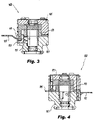
Fig. 3 is a cross-sectional view of the embodiment ofFig. 1 , sectioned along line 3-3 ofFig. 2 ; -
Fig. 4 is a cross-sectional view of the embodiment ofFig. 1 , sectioned along line 4-4 ofFig. 2 ; and -
Fig. 5 is an exploded view of the embodiment ofFig. 1 . - Reference will now be made to the drawings wherein like reference numerals identify similar structural features or aspects of the subject disclosure. For purposes of explanation and illustration, and not limitation, an illustrative view of an embodiment of an assembly in accordance with the disclosure is shown in
Fig. 1 and is designated generally byreference character 100. Other embodiments and/or aspects of this disclosure are shown inFigs. 2-5 . Certain embodiments described herein can be used as a resistor assembly for an electrical machine having rotating diodes, for example, or for any other suitable use. - Referring to
Figs. 1-5 , a rotatingresistor assembly 100, e.g., for use in a rotating shaft (not shown) of an electrical machine can include afirst housing 101 configured to contact the rotating shaft and be grounded to the rotating shaft. Thefirst housing 101 can include a first busbar connection aperture 103 configured to receive a first bus bar (e.g.,first bus bar 105 as shown). - The
assembly 100 can include asecond housing 107 configured to connect to the first housing 101 (e.g., via one ormore fasteners 108 inserted throughfirst housing 101 as shown, and/or in any other suitable manner). Thesecond housing 107 can be configured to be insulated from the rotating shaft and to be insulated from direct electrical connection with thefirst housing 101. Thesecond housing 107 can include a second busbar connection aperture 109 configured to receive a second bus bar (e.g.,second bus bar 111 as shown). - The
assembly 100 can include asuppression resistor 113 disposed between thefirst housing 101 and thesecond housing 107, and in electrical communication with thefirst housing 101 and thesecond housing 107 to provide an electrical pathway betweenfirst housing 101 and thesecond housing 107. For example, the electrical pathway through thesuppression resistor 113 can be a path of least resistance between thefirst housing 101 and thesecond housing 107. - The
first housing 101 can be made of metal or any other suitable material. For example, thefirst housing 101 can be made of aluminum. Thefirst housing 101 can be uncoated (i.e., uninsulated), for example. - The
second housing 107 can be made of metal and can include a coating (e.g., on an outer surface thereof) such that direct contact with the shaft (and/or the first housing 101) does not electrically connect the shaft to the second housing 107 (and/or thesecond housing 107 to the first housing 101). The metal can be aluminum and the coating can be a dielectric, for example (e.g., applied via Electric Phosphorus Deposition, HML, or any suitable process). It is contemplated that an inner surface of the secondbus bar aperture 109 may not be insulated such that a bus bar inserted therein is electrically connected to thesecond housing 107. Any other suitable material for the second housing 107 (e.g., uncoated ceramic) and/or any coating thereof is contemplated herein, as long as an electrical pathway is made or exists through the suppression resistor to thefirst housing 101. - An insulating
washer 115 can be disposed between and in contact with thefirst housing 101 and thesecond housing 107, e.g., to at least provide abrasion resistance to protect the coating of thesecond housing 107. The insulatingwasher 115 can provide additional electrical insulation between thefirst housing 101 and the second housing 107 (e.g., to assist in defining a path of least resistance through thesuppression resistor 113. The insulatingwasher 115 can be made of polyimide film, for example. - The
second housing 107 can include aradial aperture 117 defined from a center of thesecond housing 107 to an outer surface of thesecond housing 107, for example. Any other suitableradial aperture 117 is contemplated herein. Thefirst housing 101 can include atab 119 extending axially therefrom. Thetab 119 can define the first busbar connection aperture 103, e.g., as shown, and can be configured to insert into theradial aperture 117 of thesecond housing 107, e.g., to axially align the firstbus bar aperture 105 and the second bus bar aperture 109 (e.g., such that the bus bars 105, 111 can be substantially co-planar as shown). - As shown, the
assembly 100 can define a central aperture therethrough, e.g., through each component of theassembly 100. Any suitable other apertures in one or more components of theassembly 100 are contemplated herein. - The
suppression resistor 113 can be at least partially (e.g., fully as shown) encased within thefirst housing 101 and thesecond housing 107. In certain embodiments, thesuppression resistor 113 can be a ceramic hollow cylinder. Theassembly 100 can include afirst bus bar 105 disposed in the firstbus bar aperture 103 and asecond bus bar 111 inserted in the secondbus bar aperture 109, e.g., as shown inFig. 5 . In certain embodiments, thesecond housing 121 can include ascrew mount hole 121 configured to receive a screw to fix theassembly 100 to the shaft (not show). - In certain embodiments, the
assembly 100 may have any suitable additional components (e.g., a Bellville washer between housings to provide positive contact) as appreciated by those having ordinary skill in the art in view of this disclosure. In certain embodiments, theassembly 100 may not include additional components. - A rotor assembly for an electrical machine can include a rotor (e.g., a shaft as disclosed above), a rectifier diode pack (not shown) disposed in the rotor, and a rotating resistor assembly, e.g., 100 disposed in the rotor and in electrical communication with the rectifier diode pack. The rotating resistor assembly, e.g., 100 can be any suitable assembly as disclosed herein. Any other suitable components as appreciated by those having ordinary skill in the art.
- Certain embodiments can include a positive and negative rail (housings), e.g., made from aluminum. The positive rail (e.g., second housing) can be coated with an insulating material. The high impedance resistor of traditional assemblies can be eliminated because the negative rail, e.g., the first housing, can be supported by the shaft making a direct ground connection.
- Embodiments can be a three or four piece assembly that utilizes the housings as the electrical conducting paths. In embodiments with only two housings halves, one housing can be insulated and the other housing can form the grounding path. Embodiments allow for cost reduction, improved manufacturing by eliminating materials of concern, increased reliability by eliminating solder/braze joints with mechanical connections, and part count reduction.
- Those having ordinary skill in the art understand that any numerical values disclosed herein can be exact values or can be values within a range. Further, any terms of approximation (e.g., "about", "approximately", "around") used in this disclosure can mean the stated value within a range. For example, in certain embodiments, the range can be within (plus or minus) 20%, or within 10%, or within 5%, or within 2%, or within any other suitable percentage or number as appreciated by those having ordinary skill in the art (e.g., for known tolerance limits or error ranges).
- Any suitable combination(s) of any disclosed embodiments and/or any suitable portion(s) thereof are contemplated herein as appreciated by those having ordinary skill in the art.
- The embodiments of the present disclosure, as described above and shown in the drawings, provide for improvement in the art to which they pertain. While the subject disclosure includes reference to certain embodiments, those skilled in the art will readily appreciate that changes and/or modifications may be made thereto without departing from the spirit and scope of the subject disclosure.
Claims (11)
- A rotating resistor assembly (100) for use in a rotating shaft of an electrical machine, comprising:a first housing (101) configured to contact the rotating shaft and be grounded to the rotating shaft, the first housing (101) comprising a first bus bar connection aperture (103) configured to receive a first bus bar (105);a second housing (107) configured to connect to the first housing (101), wherein the second housing (107) is configured to be insulated from the rotating shaft and to be insulated from direct electrical connection with the first housing (101), the second housing (107) comprising a second bus bar connection aperture (109) configured to receive a second bus bar (111); anda suppression resistor (113) disposed between the first housing (101) and the second housing (107) and in electrical communication with the first housing (101) and the second housing (107) to provide an electrical pathway between first housing (101) and the second housing (107), and wherein the second housing (107) includes a radial aperture (117) defined from a center of the second housing (107) to an outer surface of the second housing (107), and wherein the first housing (101) includes a tab extending axially therefrom, wherein the tab (109) defines the first bus bar connection aperture (103) and is configured to insert into the radial aperture (117) of the second housing (107) to axially align the first bus bar aperture (103) and the second bus bar aperture (109).
- The assembly of claim 1, wherein the first housing (101) is made of metal.
- The assembly of claim 2, wherein the first housing (101) is made of aluminum.
- The assembly of claim 2, wherein the second housing (107) is made of metal and includes coating such that direct contact with the shaft does not electrically connect the shaft to the second housing (107), wherein the first housing (101) is uncoated.
- The assembly of claim 4, wherein the metal is aluminum and the coating is a dielectric.
- The assembly of claim 4, further comprising an insulating washer (115) disposed between and in contact with the first housing (101) and the second housing (107) to at least provide abrasion resistance to protect the coating of the second housing (107).
- The assembly of claim 6, wherein the insulating washer (115) is made of polyimide film.
- The assembly of any preceding claim, wherein the suppression resistor (113) is at least partially encased within the first housing (101) and the second housing (107).
- The assembly of claim 8, wherein the suppression resistor (113) is a ceramic hollow cylinder.
- The assembly of any preceding claim, further comprising a first bus bar (105) disposed in the first bus bar aperture (103) and a second bus bar (111) inserted in the second bus bar aperture (109).
- A rotor assembly for an electrical machine, comprising:a rotor;a rectifier diode pack disposed in the rotor; andthe rotating resistor assembly of any preceding claim, disposed in the rotor and in electrical communication with the rectifier diode pack.
Applications Claiming Priority (2)
| Application Number | Priority Date | Filing Date | Title |
|---|---|---|---|
| US16/242,930 US10879772B2 (en) | 2019-01-08 | 2019-01-08 | Rotating resistor assemblies |
| EP19209828.3A EP3681020B1 (en) | 2019-01-08 | 2019-11-18 | Rotating resistor assemblies |
Related Parent Applications (1)
| Application Number | Title | Priority Date | Filing Date |
|---|---|---|---|
| EP19209828.3A Division EP3681020B1 (en) | 2019-01-08 | 2019-11-18 | Rotating resistor assemblies |
Publications (1)
| Publication Number | Publication Date |
|---|---|
| EP4096071A1 true EP4096071A1 (en) | 2022-11-30 |
Family
ID=68610054
Family Applications (2)
| Application Number | Title | Priority Date | Filing Date |
|---|---|---|---|
| EP22185718.8A Pending EP4096071A1 (en) | 2019-01-08 | 2019-11-18 | Rotating resistor assemblies |
| EP19209828.3A Active EP3681020B1 (en) | 2019-01-08 | 2019-11-18 | Rotating resistor assemblies |
Family Applications After (1)
| Application Number | Title | Priority Date | Filing Date |
|---|---|---|---|
| EP19209828.3A Active EP3681020B1 (en) | 2019-01-08 | 2019-11-18 | Rotating resistor assemblies |
Country Status (2)
| Country | Link |
|---|---|
| US (1) | US10879772B2 (en) |
| EP (2) | EP4096071A1 (en) |
Families Citing this family (4)
| Publication number | Priority date | Publication date | Assignee | Title |
|---|---|---|---|---|
| US11539270B2 (en) | 2020-03-13 | 2022-12-27 | Hamilton Sundstrand Corporation | Connection assembly cover with integrated anti-rotation |
| US20220293303A1 (en) * | 2021-03-13 | 2022-09-15 | Hamilton Sundstrand Corporation | Resistor support assembly with spring seat |
| US11799391B2 (en) | 2021-03-13 | 2023-10-24 | Hamilton Sundstrand Corporation | Diode mounting ring with contact band inserts |
| US11949294B2 (en) | 2021-03-13 | 2024-04-02 | Hamilton Sundstrand Corporation | Resistor plate assembly with contact bands |
Citations (5)
| Publication number | Priority date | Publication date | Assignee | Title |
|---|---|---|---|---|
| US5587616A (en) * | 1993-05-04 | 1996-12-24 | Sundstrand Corporation | Rotor for a dynamoelectric machine having a one-piece rotation rectifier |
| US20140226383A1 (en) * | 2013-02-11 | 2014-08-14 | Hamilton Sundstrand Corporation | Coaxial rotating rectifier package assembly for generator |
| US20140241020A1 (en) * | 2013-02-22 | 2014-08-28 | Hamilton Sundstrand Corporation | Rotating rectifier assembly and method |
| EP2773031A2 (en) * | 2013-03-01 | 2014-09-03 | Hamilton Sundstrand Corporation | Connector and spring assembly for a generator |
| US9035508B2 (en) * | 2012-05-08 | 2015-05-19 | Hamilton Sundstrand Corporation | Rotating resistor assembly |
Family Cites Families (13)
| Publication number | Priority date | Publication date | Assignee | Title |
|---|---|---|---|---|
| US4794510A (en) * | 1986-12-23 | 1988-12-27 | Sundstrand Corporation | Rectifier assembly |
| US5065484A (en) * | 1989-04-14 | 1991-11-19 | Sundstrand Corporation | Rotating rectifier assembly |
| US7586224B2 (en) * | 2005-11-16 | 2009-09-08 | Hamilton Sundstrand Corporation | Rotating rectifier assembly |
| US7868494B2 (en) | 2008-08-26 | 2011-01-11 | Hamilton Sundstrand Corporation | Rectifier assembly |
| US7944100B2 (en) | 2009-05-06 | 2011-05-17 | Hamilton Sundstrand Corporation | Generator rectifier assembly with ease of assembly features |
| GB201101700D0 (en) | 2011-02-01 | 2011-03-16 | Goodrich Control Sys | Rotating rectifier |
| US9257886B2 (en) | 2012-05-15 | 2016-02-09 | Hamilton Sundstrand Corporation | Rotating rectifier assembly bus bar |
| US9369029B2 (en) | 2013-02-27 | 2016-06-14 | Ge Aviation Systems Llc | Rotating rectifier assembly for electric machine |
| US9490674B2 (en) | 2013-12-22 | 2016-11-08 | Ge Aviation Systems Llc | Rotating rectifier assembly for electric machine |
| US9590477B2 (en) | 2014-04-10 | 2017-03-07 | Ge Aviation Systems Llc | Rotating rectifier assembly for electric machine |
| US10103604B2 (en) | 2014-07-11 | 2018-10-16 | Ge Aviation Systems Llc | Rotating rectifier assembly for electric machine |
| US11139723B2 (en) * | 2017-04-28 | 2021-10-05 | Hamilton Sundstrand Corporation | Rotating rectifier assembly |
| US10460861B1 (en) * | 2018-10-29 | 2019-10-29 | Hamilton Sundstrand Corporation | High speed rotor connection assembly |
-
2019
- 2019-01-08 US US16/242,930 patent/US10879772B2/en active Active
- 2019-11-18 EP EP22185718.8A patent/EP4096071A1/en active Pending
- 2019-11-18 EP EP19209828.3A patent/EP3681020B1/en active Active
Patent Citations (5)
| Publication number | Priority date | Publication date | Assignee | Title |
|---|---|---|---|---|
| US5587616A (en) * | 1993-05-04 | 1996-12-24 | Sundstrand Corporation | Rotor for a dynamoelectric machine having a one-piece rotation rectifier |
| US9035508B2 (en) * | 2012-05-08 | 2015-05-19 | Hamilton Sundstrand Corporation | Rotating resistor assembly |
| US20140226383A1 (en) * | 2013-02-11 | 2014-08-14 | Hamilton Sundstrand Corporation | Coaxial rotating rectifier package assembly for generator |
| US20140241020A1 (en) * | 2013-02-22 | 2014-08-28 | Hamilton Sundstrand Corporation | Rotating rectifier assembly and method |
| EP2773031A2 (en) * | 2013-03-01 | 2014-09-03 | Hamilton Sundstrand Corporation | Connector and spring assembly for a generator |
Also Published As
| Publication number | Publication date |
|---|---|
| US20200220433A1 (en) | 2020-07-09 |
| EP3681020B1 (en) | 2022-07-20 |
| EP3681020A1 (en) | 2020-07-15 |
| US10879772B2 (en) | 2020-12-29 |
Similar Documents
| Publication | Publication Date | Title |
|---|---|---|
| EP3681020B1 (en) | Rotating resistor assemblies | |
| US4806814A (en) | Half-wave rotary rectifier assembly | |
| US11569594B2 (en) | Terminal block assemblies | |
| JPS61501065A (en) | rotating rectifier assembly | |
| US9035508B2 (en) | Rotating resistor assembly | |
| EP2793374B1 (en) | Terminal assembly for electric machine | |
| US4482827A (en) | Axially and radially compact full wave rectifier assembly for an alternator | |
| EP3758201A1 (en) | High speed generator connection assembly | |
| US7948127B2 (en) | Connection method for rotating rectifiers on a generator | |
| US6859019B2 (en) | System and method for coupling rectifiers of an exciter to the rotor of a main generator | |
| CN112202262A (en) | Power distribution unit | |
| US6304013B1 (en) | Line termination network assembly for an electric motor | |
| US6624547B1 (en) | Power system having stator coils for grading voltage between inner vent tubes and coil strands and associated methods | |
| US4590397A (en) | Terminal block for dynamoelectric machine | |
| EP2793373A2 (en) | Terminal block cover | |
| EP0154630B1 (en) | Compact resistor assembly for rotary electric machine | |
| US20230188079A1 (en) | Motor with transient voltage suppression | |
| EP4068590A1 (en) | Diode mounting ring with contact band inserts | |
| US20240030787A1 (en) | Electric connection for a rotor winding of an electrical generator | |
| CN109510359A (en) | Power distribution equipment and motor |
Legal Events
| Date | Code | Title | Description |
|---|---|---|---|
| PUAI | Public reference made under article 153(3) epc to a published international application that has entered the european phase |
Free format text: ORIGINAL CODE: 0009012 |
|
| STAA | Information on the status of an ep patent application or granted ep patent |
Free format text: STATUS: THE APPLICATION HAS BEEN PUBLISHED |
|
| AC | Divisional application: reference to earlier application |
Ref document number: 3681020 Country of ref document: EP Kind code of ref document: P |
|
| AK | Designated contracting states |
Kind code of ref document: A1 Designated state(s): AL AT BE BG CH CY CZ DE DK EE ES FI FR GB GR HR HU IE IS IT LI LT LU LV MC MK MT NL NO PL PT RO RS SE SI SK SM TR |
|
| STAA | Information on the status of an ep patent application or granted ep patent |
Free format text: STATUS: REQUEST FOR EXAMINATION WAS MADE |
|
| 17P | Request for examination filed |
Effective date: 20230525 |
|
| RBV | Designated contracting states (corrected) |
Designated state(s): AL AT BE BG CH CY CZ DE DK EE ES FI FR GB GR HR HU IE IS IT LI LT LU LV MC MK MT NL NO PL PT RO RS SE SI SK SM TR |