EP3758201A1 - High speed generator connection assembly - Google Patents
High speed generator connection assembly Download PDFInfo
- Publication number
- EP3758201A1 EP3758201A1 EP19215714.7A EP19215714A EP3758201A1 EP 3758201 A1 EP3758201 A1 EP 3758201A1 EP 19215714 A EP19215714 A EP 19215714A EP 3758201 A1 EP3758201 A1 EP 3758201A1
- Authority
- EP
- European Patent Office
- Prior art keywords
- negative
- positive
- connection
- rail
- assembly
- Prior art date
- Legal status (The legal status is an assumption and is not a legal conclusion. Google has not performed a legal analysis and makes no representation as to the accuracy of the status listed.)
- Pending
Links
Images


Classifications
-
- H—ELECTRICITY
- H02—GENERATION; CONVERSION OR DISTRIBUTION OF ELECTRIC POWER
- H02K—DYNAMO-ELECTRIC MACHINES
- H02K19/00—Synchronous motors or generators
- H02K19/16—Synchronous generators
-
- H—ELECTRICITY
- H02—GENERATION; CONVERSION OR DISTRIBUTION OF ELECTRIC POWER
- H02K—DYNAMO-ELECTRIC MACHINES
- H02K11/00—Structural association of dynamo-electric machines with electric components or with devices for shielding, monitoring or protection
- H02K11/04—Structural association of dynamo-electric machines with electric components or with devices for shielding, monitoring or protection for rectification
- H02K11/042—Rectifiers associated with rotating parts, e.g. rotor cores or rotary shafts
-
- H—ELECTRICITY
- H02—GENERATION; CONVERSION OR DISTRIBUTION OF ELECTRIC POWER
- H02K—DYNAMO-ELECTRIC MACHINES
- H02K11/00—Structural association of dynamo-electric machines with electric components or with devices for shielding, monitoring or protection
- H02K11/04—Structural association of dynamo-electric machines with electric components or with devices for shielding, monitoring or protection for rectification
Definitions
- This application relates to a high speed generator.
- Generators are known and typically have an input shaft connected to a source of rotation.
- the input shaft rotates when driven by the source of rotation causing a main field winding to rotate adjacent to a stator. Electrical energy is generated in the stator from the rotation of the main field winding.
- a DC voltage is supplied to the field winding.
- an exciter stator is positioned adjacent an exciter rotor and transmits AC three phase current to a rectifier assembly.
- the rectifier assembly rectifies the three phase AC current into a DC current.
- a positive bus and a negative bus extend from the rectifier assembly into positive and negative rails associated with a connection assembly.
- the connection assembly communicates the DC voltage through negative and positive connection to the main field winding.
- the connection assembly further includes a resistor to eliminate any undesirable effects on the transmitted DC voltage.
- connection assembly has utilized beryllium copper elements as both the positive and negative rails.
- the rails connect to terminal connections that extend radially outwardly to be connected to the main field winding.
- the terminal connections have an inner tang extending into a spring clip associated with the positive and negative rails.
- the spring clips sit in members formed of a plastic.
- a suppression resistor is included as well as a high impedance resistor.
- a rotor pack for a generator has an exciter rotor rotating with a shaft.
- a rectifier assembly is in electric communication with the exciter rotor to receive AC current and rectify the AC current into a DC voltage.
- Positive and negative busses extend from the rectifier assembly to a negative rail and a positive rail on a connection assembly.
- the negative rail is in contact with the shaft to provide a ground connection.
- the negative and positive rails are formed of a metal.
- the negative and positive rails are connected to a main field winding.
- a high speed generator is also disclosed.
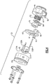
- Figure 1 shows a high speed generator 20 receiving an input 22.
- Input 22 may be a shaft driven by a turbine in an associated gas turbine engine such as found on an aircraft.
- the input 22 drives a shaft 21 and another shaft 23.
- An exciter stator 24 surrounds an exciter rotor 26.
- a rectifier assembly 28 rotates with the exciter rotor 26 and the shafts 21 and 23.
- a negative bus 30N is illustrated extending from the rectifier assembly 28. It should be understood that a positive bus also extends from the rectifier assembly 28, but would not be visible in this view.
- Figure 2 shows the rectifier pack 28 having positive and negative busses 30P and 30N extending toward connection assembly 32.
- connection assembly 32 includes an insulator 40 formed of a plastic, a positive rail 42, which receives the bus 30P, and negative rail 44 which receiver bus 30N.
- Positive rail 42 and negative rail 44 are each formed of aluminum.
- the negative rail 44 has a bore 47.
- An outer surface 46 of negative rail is in contact with an inner surface 17 of shaft 21 to provide a ground connection. This allows the elimination of the prior impedance resistor. Instead, the negative rail 44 makes a direct ground connection.
- Connections or terminals 35 and 34 are shown that communicate the negative and positive rails to the main field winding 36.
- three phase AC current is supplied from the exciter stator 24 to the exciter rotor 26. That three phase AC current is rectified to DC by the rectifier assembly 28 and supplied to the connection assembly 32. Then, from the connection assembly 32 the positive and negative connections 34 and 35 are connected to the main field winding 36. Main stator 38 is also shown.
- the shafts 21 and 23, rectifier assembly 28, connection assembly 32, main field winding 36 and associated connection components could be called a rotor pack 19.
- the input 22 causes the rotor pack 19 to rotate and electric power is generated at the main stator 38.
- Spring 72 formed of metal sits in bore 47 and thus provide an electric connection to negative rail 44. Spring also biases ceramic suppression register into positive rail 42.
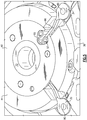
- Figure 3 shows the connections 34 and 35 extending from the connection assembly 32.
- Cover 50 is shown as well as insulator 40 and negative rail 44.
- Insulator 40 is shown to have a plug 60 extending into a slot 65 on the negative rail 44.
- Figure 4 is an exploded view of the several components.
- Figure 4 also shows pin connection 130N and 130P which receive the busses 30P and 30N from the rectifier assembly 28.
- Spring clip 62 is associated with pin 130P and received within a pocket 61 in the plug 60 of insulator 40.
- a spring clip 64 will receive the negative pin 130N and be received in another pocket in the negative rail 44.
- Ceramic suppression resistor 70 is shown as is retention spring 72. As mentioned, retention spring 72 biases the resistor against both positive rail 42 and negative rail 44.
- the spring clips 62 and 64 are formed copper springs. They sit compressed within pockets such that they flex outward in the pockets maintaining a positive lock against their respective housings.
- Figure 5 shows the connection 34 pinned at 80 to the main filed winding 36. Further, the connector 34 has a tang 99 received in spring clip 62. Spring clip 52 sit compressed in a pocket 97 in the insulator 40.
- Figure 6 shows the plug 60 receiving spring clip 62 and connector 34, tang 99.
- Spring clip 64 is also disposed in the pocket 100 formed in a forward face 101 of the negative rail 44.
- the spring clip 64 Since the spring clip 64 is received within pocket 100 formed in a metal member, the spring clip is not likely to deform pocket 100.
- the pocket in the prior art was formed in a plastic member, which could deform thereby reducing the compressed force holding the spring clip against tang 99 of the connection 35.
- connection pin 130P extends into one loop 140 of the spring clip 62 to communicate the positive connection to the spring clip and then to tang 99 of the connector 34.
- the connection pin 130N is also shown in a spring half 140.
- a rotor pack 19 for a generator 20 includes an exciter rotor 26 rotating with a shaft 21.
- a rectifier assembly 28 in an electric communication with the exciter rotor 26 to receive AC current and rectify the AC current into a DC voltage.
- Connection busses 30P/30N extend from the rectifier assembly 28 with a negative bus 30N extending into a negative rail 44 on a connection assembly 32.
- a positive bus 30P connects into a positive rail 42 on the connection assembly 32.
- the negative rail 44 is in contact with the shaft 21 to provide a ground connection for the negative rail.
- the negative and positive rails 42/44 are formed of a metal.
- the negative and positive rails 42/44 connect to a main field winding 36.
- the negative bus 30N extends into a negative pin 130N.
- the negative pin 130N is connected to provide a negative connection to a spring clip 64 received in a pocket 100 in the negative rail 44.
- a negative electric connector 35 extends radially outwardly from the negative rail 44 to provide a negative connection to the main field winding 36.
- the negative spring clip 64 includes a pair of loops 140 with the negative pin 130N extending into one of the loops and the negative connection 35/99 is received between the loops.
- the loops 140 are biased toward each other and against the negative connection 35/99 when received in the pocket 100.
- the negative rail 44 includes a groove 65 receiving a plug 60 from an insulator 40, and a positive spring clip 62 is received within a pocket 47 in the insulator plug.
- the positive spring clip 62 includes a pair of loops 140 with the positive pin 130P extending into one of the loops and the positive connection 34/99 being received between the loops 140.
- the loops are biased toward each other and against the positive connection when received in the pocket 97.
Landscapes
- Engineering & Computer Science (AREA)
- Power Engineering (AREA)
- Synchronous Machinery (AREA)
Abstract
Description
- This application relates to a high speed generator.
- Generators are known and typically have an input shaft connected to a source of rotation. The input shaft rotates when driven by the source of rotation causing a main field winding to rotate adjacent to a stator. Electrical energy is generated in the stator from the rotation of the main field winding.
- A DC voltage is supplied to the field winding. In known generators, an exciter stator is positioned adjacent an exciter rotor and transmits AC three phase current to a rectifier assembly. The rectifier assembly rectifies the three phase AC current into a DC current. A positive bus and a negative bus extend from the rectifier assembly into positive and negative rails associated with a connection assembly. The connection assembly communicates the DC voltage through negative and positive connection to the main field winding. The connection assembly further includes a resistor to eliminate any undesirable effects on the transmitted DC voltage.
- In the past, the connection assembly has utilized beryllium copper elements as both the positive and negative rails. The rails connect to terminal connections that extend radially outwardly to be connected to the main field winding. The terminal connections have an inner tang extending into a spring clip associated with the positive and negative rails. The spring clips sit in members formed of a plastic. In addition, a suppression resistor is included as well as a high impedance resistor.
- A rotor pack for a generator has an exciter rotor rotating with a shaft. A rectifier assembly is in electric communication with the exciter rotor to receive AC current and rectify the AC current into a DC voltage. Positive and negative busses extend from the rectifier assembly to a negative rail and a positive rail on a connection assembly. The negative rail is in contact with the shaft to provide a ground connection. The negative and positive rails are formed of a metal. The negative and positive rails are connected to a main field winding.
- A high speed generator is also disclosed.
- These and other features may be best understood from the following drawings and specification.
-
-
Figure 1 shows a high speed generator. -
Figure 2 shows a connection of a rectifier assembly to a connection assembly. -
Figure 3 shows a connection assembly. -
Figure 4 is an exploded view of the connection assembly. -
Figure 5 is a cross-sectional view. -
Figure 6 shows a distinct cross-section through the connector pack. -
Figure 1 shows ahigh speed generator 20 receiving aninput 22.Input 22 may be a shaft driven by a turbine in an associated gas turbine engine such as found on an aircraft. Theinput 22 drives ashaft 21 and anothershaft 23. - An exciter
stator 24 surrounds an exciterrotor 26. Arectifier assembly 28 rotates with theexciter rotor 26 and theshafts negative bus 30N is illustrated extending from therectifier assembly 28. It should be understood that a positive bus also extends from therectifier assembly 28, but would not be visible in this view. -
Figure 2 shows therectifier pack 28 having positive andnegative busses connection assembly 32. - The operation of the structure to this point may generally be as known.
- Returning to
Figure 1 , theconnection assembly 32 includes aninsulator 40 formed of a plastic, apositive rail 42, which receives thebus 30P, andnegative rail 44 which receiver bus 30N.Positive rail 42 andnegative rail 44 are each formed of aluminum. Thenegative rail 44 has abore 47. Anouter surface 46 of negative rail is in contact with aninner surface 17 ofshaft 21 to provide a ground connection. This allows the elimination of the prior impedance resistor. Instead, thenegative rail 44 makes a direct ground connection. - Connections or
terminals - In practice, three phase AC current is supplied from the
exciter stator 24 to theexciter rotor 26. That three phase AC current is rectified to DC by therectifier assembly 28 and supplied to theconnection assembly 32. Then, from theconnection assembly 32 the positive andnegative connections Main stator 38 is also shown. - The
shafts rectifier assembly 28,connection assembly 32, main field winding 36 and associated connection components could be called arotor pack 19. As mentioned above, during operation, theinput 22 causes therotor pack 19 to rotate and electric power is generated at themain stator 38. -
Spring 72, formed of metal sits inbore 47 and thus provide an electric connection tonegative rail 44. Spring also biases ceramic suppression register intopositive rail 42. -
Figure 3 shows theconnections connection assembly 32.Cover 50 is shown as well asinsulator 40 andnegative rail 44.Insulator 40 is shown to have aplug 60 extending into aslot 65 on thenegative rail 44. -
Figure 4 is an exploded view of the several components.Figure 4 also showspin connection busses rectifier assembly 28.Spring clip 62 is associated withpin 130P and received within apocket 61 in theplug 60 ofinsulator 40. Aspring clip 64 will receive thenegative pin 130N and be received in another pocket in thenegative rail 44.Ceramic suppression resistor 70 is shown as isretention spring 72. As mentioned,retention spring 72 biases the resistor against bothpositive rail 42 andnegative rail 44. - The spring clips 62 and 64 are formed copper springs. They sit compressed within pockets such that they flex outward in the pockets maintaining a positive lock against their respective housings.
-
Figure 5 shows theconnection 34 pinned at 80 to the main filed winding 36. Further, theconnector 34 has atang 99 received inspring clip 62. Spring clip 52 sit compressed in apocket 97 in theinsulator 40. -
Figure 6 shows theplug 60 receivingspring clip 62 andconnector 34,tang 99.Spring clip 64 is also disposed in thepocket 100 formed in aforward face 101 of thenegative rail 44. - Since the
spring clip 64 is received withinpocket 100 formed in a metal member, the spring clip is not likely to deformpocket 100. The pocket in the prior art was formed in a plastic member, which could deform thereby reducing the compressed force holding the spring clip againsttang 99 of theconnection 35. - As shown, the
connection pin 130P extends into oneloop 140 of thespring clip 62 to communicate the positive connection to the spring clip and then totang 99 of theconnector 34. Theconnection pin 130N is also shown in aspring half 140. - A
rotor pack 19 for agenerator 20 includes anexciter rotor 26 rotating with ashaft 21. Arectifier assembly 28 in an electric communication with theexciter rotor 26 to receive AC current and rectify the AC current into a DC voltage. Connection busses 30P/30N extend from therectifier assembly 28 with anegative bus 30N extending into anegative rail 44 on aconnection assembly 32. Apositive bus 30P connects into apositive rail 42 on theconnection assembly 32. Thenegative rail 44 is in contact with theshaft 21 to provide a ground connection for the negative rail. The negative andpositive rails 42/44 are formed of a metal. The negative andpositive rails 42/44 connect to a main field winding 36. - The
negative bus 30N extends into anegative pin 130N. Thenegative pin 130N is connected to provide a negative connection to aspring clip 64 received in apocket 100 in thenegative rail 44. A negativeelectric connector 35 extends radially outwardly from thenegative rail 44 to provide a negative connection to the main field winding 36. - The
negative spring clip 64 includes a pair ofloops 140 with thenegative pin 130N extending into one of the loops and thenegative connection 35/99 is received between the loops. Theloops 140 are biased toward each other and against thenegative connection 35/99 when received in thepocket 100. - The
negative rail 44 includes agroove 65 receiving aplug 60 from aninsulator 40, and apositive spring clip 62 is received within apocket 47 in the insulator plug. - The
positive spring clip 62 includes a pair ofloops 140 with thepositive pin 130P extending into one of the loops and thepositive connection 34/99 being received between theloops 140. The loops are biased toward each other and against the positive connection when received in thepocket 97. - Although an embodiment of this invention has been disclosed, a worker of ordinary skill in this art would recognize that certain modifications would come within the scope of this disclosure. For that reason, the following claims should be studied to determine the true scope and content of this disclosure.
Claims (9)
- A rotating assembly for a generator (20) comprising:an exciter rotor (26) rotating with a shaft (21);a rectifier assembly (28) in electric communication with said exciter rotor to receive AC current and rectify the AC current into a DC voltage, a positive bus (30P) and a negative bus (30N) extending from said rectifier assembly, with said negative bus extending into a negative rail (44) on a connection assembly (32), and said positive bus connecting into a positive rail (42) on said connection assembly, said negative rail is in contact with said shaft to provide a ground connection for said negative rail, said negative and positive rails are formed of a metal; andsaid negative and positive rails connected to a main field winding (36).
- The rotating assembly as set forth in claim 1, wherein said positive rail and said negative rail are formed of aluminium.
- The rotating assembly as set forth in claim 1 or 2, wherein said negative bus is connected to a negative pin (130N) in said connection assembly, said negative pin is connected to provide a connection to a negative spring clip (64) received in a pocket (100) in said negative rail, and a negative electric connection (35/99) extending radially outwardly from said negative rail to provide a negative connection to said main field winding.
- The rotating assembly as set forth in claim 3, wherein said negative spring clip includes a pair of loops (140) with said negative pin extending into one of said loops and said negative electric connection being received between said loops, said loops biased toward each other and against said negative electric connection when received in said pocket.
- The rotating assembly as set forth in any preceding claim, wherein said positive bus is connected to a positive pin (130P) in said connection assembly, said positive pin is connected to provide a connection to a positive spring clip (62) received in a pocket (61) in an insulator (40), and a positive electric connection (34/99) connected to said positive spring clip, said positive electric connection extending radially outwardly from said positive spring clip to provide a positive connection to said main field.
- The rotating assembly as set forth in any preceding claim, wherein said negative rail includes a groove receiving a plug (60) from said insulator, and said positive spring clip received within a pocket in said plug.
- The rotating assembly as set forth in any preceding claim, wherein a ceramic suppression resistor is biased against said positive rail.
- The rotating assembly as set forth in claim 7, wherein a bias force on said ceramic suppression resistor is provided by a metal retention spring received in a bore in said negative rail, and in contact with said negative rail.
- A high speed generator comprising:the rotating assembly according to any preceding claim; andan exciter stator (24) surrounding the exciter rotor and a main stator (38) surrounding the main field winding.
Applications Claiming Priority (1)
| Application Number | Priority Date | Filing Date | Title |
|---|---|---|---|
| US16/456,369 US11245312B2 (en) | 2019-06-28 | 2019-06-28 | High speed generator connection assembly |
Publications (1)
| Publication Number | Publication Date |
|---|---|
| EP3758201A1 true EP3758201A1 (en) | 2020-12-30 |
Family
ID=68916196
Family Applications (1)
| Application Number | Title | Priority Date | Filing Date |
|---|---|---|---|
| EP19215714.7A Pending EP3758201A1 (en) | 2019-06-28 | 2019-12-12 | High speed generator connection assembly |
Country Status (2)
| Country | Link |
|---|---|
| US (1) | US11245312B2 (en) |
| EP (1) | EP3758201A1 (en) |
Cited By (4)
| Publication number | Priority date | Publication date | Assignee | Title |
|---|---|---|---|---|
| EP4064299A1 (en) * | 2021-03-13 | 2022-09-28 | Hamilton Sundstrand Corporation | Resistor plate assembly with contact bands |
| EP4068592A1 (en) * | 2021-03-13 | 2022-10-05 | Hamilton Sundstrand Corporation | Resistor support assembly with spring seat |
| US11532964B2 (en) * | 2020-01-22 | 2022-12-20 | Hamilton Sundstrand Corporation | Generator rotor flat wire winding |
| US11799391B2 (en) | 2021-03-13 | 2023-10-24 | Hamilton Sundstrand Corporation | Diode mounting ring with contact band inserts |
Citations (2)
| Publication number | Priority date | Publication date | Assignee | Title |
|---|---|---|---|---|
| US20130300231A1 (en) * | 2012-05-08 | 2013-11-14 | Hamilton Sundstrand Corporation | Rotating resistor assembly |
| EP2773031A2 (en) * | 2013-03-01 | 2014-09-03 | Hamilton Sundstrand Corporation | Connector and spring assembly for a generator |
Family Cites Families (5)
| Publication number | Priority date | Publication date | Assignee | Title |
|---|---|---|---|---|
| US5065484A (en) | 1989-04-14 | 1991-11-19 | Sundstrand Corporation | Rotating rectifier assembly |
| EP1708342A3 (en) * | 2005-03-31 | 2010-04-14 | ALSTOM Technology Ltd | High current rotating exciter |
| US7586224B2 (en) * | 2005-11-16 | 2009-09-08 | Hamilton Sundstrand Corporation | Rotating rectifier assembly |
| US7944100B2 (en) * | 2009-05-06 | 2011-05-17 | Hamilton Sundstrand Corporation | Generator rectifier assembly with ease of assembly features |
| US20140226383A1 (en) * | 2013-02-11 | 2014-08-14 | Hamilton Sundstrand Corporation | Coaxial rotating rectifier package assembly for generator |
-
2019
- 2019-06-28 US US16/456,369 patent/US11245312B2/en active Active
- 2019-12-12 EP EP19215714.7A patent/EP3758201A1/en active Pending
Patent Citations (2)
| Publication number | Priority date | Publication date | Assignee | Title |
|---|---|---|---|---|
| US20130300231A1 (en) * | 2012-05-08 | 2013-11-14 | Hamilton Sundstrand Corporation | Rotating resistor assembly |
| EP2773031A2 (en) * | 2013-03-01 | 2014-09-03 | Hamilton Sundstrand Corporation | Connector and spring assembly for a generator |
Cited By (6)
| Publication number | Priority date | Publication date | Assignee | Title |
|---|---|---|---|---|
| US11532964B2 (en) * | 2020-01-22 | 2022-12-20 | Hamilton Sundstrand Corporation | Generator rotor flat wire winding |
| EP4064299A1 (en) * | 2021-03-13 | 2022-09-28 | Hamilton Sundstrand Corporation | Resistor plate assembly with contact bands |
| EP4068592A1 (en) * | 2021-03-13 | 2022-10-05 | Hamilton Sundstrand Corporation | Resistor support assembly with spring seat |
| US11799391B2 (en) | 2021-03-13 | 2023-10-24 | Hamilton Sundstrand Corporation | Diode mounting ring with contact band inserts |
| US11949294B2 (en) | 2021-03-13 | 2024-04-02 | Hamilton Sundstrand Corporation | Resistor plate assembly with contact bands |
| US12009126B2 (en) | 2021-03-13 | 2024-06-11 | Hamilton Sundstrand Corporation | Resistor support assembly with spring seat |
Also Published As
| Publication number | Publication date |
|---|---|
| US11245312B2 (en) | 2022-02-08 |
| US20200412210A1 (en) | 2020-12-31 |
Similar Documents
| Publication | Publication Date | Title |
|---|---|---|
| US11245312B2 (en) | High speed generator connection assembly | |
| EP3276800B1 (en) | Integrated brushless starter generator | |
| US4806814A (en) | Half-wave rotary rectifier assembly | |
| US7944100B2 (en) | Generator rectifier assembly with ease of assembly features | |
| US8063522B2 (en) | Generator rotor ground bushing | |
| WO2007146246A2 (en) | Dual starter/generator for aircraft engine | |
| US9369029B2 (en) | Rotating rectifier assembly for electric machine | |
| US9035508B2 (en) | Rotating resistor assembly | |
| US9472996B2 (en) | Terminal assembly | |
| US20120104887A1 (en) | Automotive dynamoelectric machine | |
| US8823334B2 (en) | Method for starting an electric motor | |
| US20160208709A1 (en) | Method for starting aircraft engines | |
| EP3681020B1 (en) | Rotating resistor assemblies | |
| EP2779368A1 (en) | Rotating electrical machine for vehicle | |
| US9035507B2 (en) | Electric machine and rectifier assembly therefor | |
| US11621601B2 (en) | Generator main field connection | |
| EP2793373A2 (en) | Terminal block cover | |
| CN108288879B (en) | Stator support for an electric machine | |
| US5017821A (en) | Brushless dynamo electric machine with access to rectifier assembly | |
| EP2501022B1 (en) | Generator rotor and bleed resistor assembly | |
| US9131612B2 (en) | Automotive alternator rectifying apparatus |
Legal Events
| Date | Code | Title | Description |
|---|---|---|---|
| PUAI | Public reference made under article 153(3) epc to a published international application that has entered the european phase |
Free format text: ORIGINAL CODE: 0009012 |
|
| STAA | Information on the status of an ep patent application or granted ep patent |
Free format text: STATUS: THE APPLICATION HAS BEEN PUBLISHED |
|
| AK | Designated contracting states |
Kind code of ref document: A1 Designated state(s): AL AT BE BG CH CY CZ DE DK EE ES FI FR GB GR HR HU IE IS IT LI LT LU LV MC MK MT NL NO PL PT RO RS SE SI SK SM TR |
|
| AX | Request for extension of the european patent |
Extension state: BA ME |
|
| STAA | Information on the status of an ep patent application or granted ep patent |
Free format text: STATUS: REQUEST FOR EXAMINATION WAS MADE |
|
| 17P | Request for examination filed |
Effective date: 20210324 |
|
| RBV | Designated contracting states (corrected) |
Designated state(s): AL AT BE BG CH CY CZ DE DK EE ES FI FR GB GR HR HU IE IS IT LI LT LU LV MC MK MT NL NO PL PT RO RS SE SI SK SM TR |
|
| STAA | Information on the status of an ep patent application or granted ep patent |
Free format text: STATUS: EXAMINATION IS IN PROGRESS |
|
| 17Q | First examination report despatched |
Effective date: 20220621 |