EP4096022B1 - Computergesteuertes elektromechanisches mmw-frequenz-antennenabtastsystem und dessen strahlsteuerung - Google Patents
Computergesteuertes elektromechanisches mmw-frequenz-antennenabtastsystem und dessen strahlsteuerung Download PDFInfo
- Publication number
- EP4096022B1 EP4096022B1 EP22172871.0A EP22172871A EP4096022B1 EP 4096022 B1 EP4096022 B1 EP 4096022B1 EP 22172871 A EP22172871 A EP 22172871A EP 4096022 B1 EP4096022 B1 EP 4096022B1
- Authority
- EP
- European Patent Office
- Prior art keywords
- microstrip antenna
- metasurface
- predetermined distance
- antenna
- scanning system
- Prior art date
- Legal status (The legal status is an assumption and is not a legal conclusion. Google has not performed a legal analysis and makes no representation as to the accuracy of the status listed.)
- Active
Links
Images


Classifications
-
- H—ELECTRICITY
- H01—ELECTRIC ELEMENTS
- H01Q—ANTENNAS, i.e. RADIO AERIALS
- H01Q3/00—Arrangements for changing or varying the orientation or the shape of the directional pattern of the waves radiated from an antenna or antenna system
- H01Q3/12—Arrangements for changing or varying the orientation or the shape of the directional pattern of the waves radiated from an antenna or antenna system using mechanical relative movement between primary active elements and secondary devices of antennas or antenna systems
- H01Q3/14—Arrangements for changing or varying the orientation or the shape of the directional pattern of the waves radiated from an antenna or antenna system using mechanical relative movement between primary active elements and secondary devices of antennas or antenna systems for varying the relative position of primary active element and a refracting or diffracting device
-
- H—ELECTRICITY
- H01—ELECTRIC ELEMENTS
- H01Q—ANTENNAS, i.e. RADIO AERIALS
- H01Q3/00—Arrangements for changing or varying the orientation or the shape of the directional pattern of the waves radiated from an antenna or antenna system
- H01Q3/02—Arrangements for changing or varying the orientation or the shape of the directional pattern of the waves radiated from an antenna or antenna system using mechanical movement of antenna or antenna system as a whole
- H01Q3/08—Arrangements for changing or varying the orientation or the shape of the directional pattern of the waves radiated from an antenna or antenna system using mechanical movement of antenna or antenna system as a whole for varying two co-ordinates of the orientation
-
- H—ELECTRICITY
- H01—ELECTRIC ELEMENTS
- H01Q—ANTENNAS, i.e. RADIO AERIALS
- H01Q15/00—Devices for reflection, refraction, diffraction or polarisation of waves radiated from an antenna, e.g. quasi-optical devices
- H01Q15/0006—Devices acting selectively as reflecting surface, as diffracting or as refracting device, e.g. frequency filtering or angular spatial filtering devices
- H01Q15/006—Selective devices having photonic band gap materials or materials of which the material properties are frequency dependent, e.g. perforated substrates, high-impedance surfaces
-
- H—ELECTRICITY
- H01—ELECTRIC ELEMENTS
- H01Q—ANTENNAS, i.e. RADIO AERIALS
- H01Q19/00—Combinations of primary active antenna elements and units with secondary devices, e.g. with quasi-optical devices, for giving the antenna a desired directional characteristic
- H01Q19/06—Combinations of primary active antenna elements and units with secondary devices, e.g. with quasi-optical devices, for giving the antenna a desired directional characteristic using refracting or diffracting devices, e.g. lens
- H01Q19/062—Combinations of primary active antenna elements and units with secondary devices, e.g. with quasi-optical devices, for giving the antenna a desired directional characteristic using refracting or diffracting devices, e.g. lens for focusing
-
- H—ELECTRICITY
- H01—ELECTRIC ELEMENTS
- H01Q—ANTENNAS, i.e. RADIO AERIALS
- H01Q3/00—Arrangements for changing or varying the orientation or the shape of the directional pattern of the waves radiated from an antenna or antenna system
- H01Q3/22—Arrangements for changing or varying the orientation or the shape of the directional pattern of the waves radiated from an antenna or antenna system varying the orientation in accordance with variation of frequency of radiated wave
-
- H—ELECTRICITY
- H01—ELECTRIC ELEMENTS
- H01Q—ANTENNAS, i.e. RADIO AERIALS
- H01Q9/00—Electrically-short antennas having dimensions not more than twice the operating wavelength and consisting of conductive active radiating elements
- H01Q9/04—Resonant antennas
- H01Q9/0407—Substantially flat resonant element parallel to ground plane, e.g. patch antenna
- H01Q9/0414—Substantially flat resonant element parallel to ground plane, e.g. patch antenna in a stacked or folded configuration
-
- H—ELECTRICITY
- H01—ELECTRIC ELEMENTS
- H01Q—ANTENNAS, i.e. RADIO AERIALS
- H01Q9/00—Electrically-short antennas having dimensions not more than twice the operating wavelength and consisting of conductive active radiating elements
- H01Q9/04—Resonant antennas
- H01Q9/0407—Substantially flat resonant element parallel to ground plane, e.g. patch antenna
- H01Q9/0421—Substantially flat resonant element parallel to ground plane, e.g. patch antenna with a shorting wall or a shorting pin at one end of the element
Definitions
- the disclosure herein generally relates to antenna scanning systems, and, more particularly, computer controlled electromechanical Millimeter Wave (MMW) frequency antenna scanning system and beam steering for the same.
- MMW computer controlled electromechanical Millimeter Wave
- Millimeter Wave (MMW) frequency band of 24GHz to 28GHz is being considered quite important for emerging areas of Radio Frequency (RF) sensing (radars in civilian applications) and 5 th Generation (5G) deployments in wireless communications.
- RF Radio Frequency
- 5G 5 th Generation
- RF applications range from machine inspection (by measuring vibration), counting people and tracking, and the like.
- future 5G deployments will utilize this frequency band for very high data rate.
- Omnidirectional antenna has the property of low gain thereby requiring more transmit power; this is critical at MMW frequency bands due to high propagation loss. Moreover, an omnidirectional antenna will pick up radio waves from both the desired object (or user) as well as interfering sources; thereby making detection more difficult.
- phased-array concept works well with a narrow band system.
- An array factor that defines the directivity and beam scanning angle is frequency sensitive. Both values change as the operating frequency changes and therefore the array needs to be reconfigured when the system is wideband. Typically, bandwidth > 10% of center frequency.
- the emerging areas of 5G or ultra-wideband radar expect a frequency bandwidth of greater than 20% or 500MHz.
- conventional concepts like multiband array, a frequency tapered array and an array with varying element sizes and element distances may be employed. Cost and size of the antenna scanning system is a concern with these conventional concepts.
- Phase-gradient metasurfaces also known as phase-shifting surfaces, are used to steer the beam of medium-to-high gain antennas. Almost all such surfaces are made of cell elements that are similar in shape and only differ in dimensional parameters to achieve the required spatial phase gradient. A limitation of using the same geometry for the cell elements is that only limited phase shift range can be achieved while maintaining high transmission through each cell. A new strategy of integrating geometrically different cell elements, having different transmission phase and amplitude characteristics, is presented in this article. To demonstrate the concept, four different cell geometries are considered. The results indicate that the hybrid approach allows the designer to achieve the required phase shift range together with a high transmission with thinner metasurfaces having fewer dielectric and metal layers.
- RABBANI MUHAMMAD SAQIB ET AL "Electro-mechanically tunable metasurfaces are presented for high gain, beam steerable Leaky-Wave Antennas ⁇ LWAS) at 37 GHz and 230 GHz bands.
- the proposed metasurfaces are: a tunable High Impedance Surface (EDS) in case of 37 GHz LWA, and tunable Partially Reflective Surface ⁇ PRS) in case of 28) GHz LWA.
- the proposed metasurfaces serve as a phase shifter in the beam steering antenna.
- the required phase shift is achieved by varying the mechanical separation between the HIS/PRS periodic array and ground layer using a piezoelectric actuator (PEA).
- PPA piezoelectric actuator
- the presented phase shifting technique offers an extremely low loss solution for antenna beam steering at num-wave frequencies.
- the designed antenna at the selected frequency bands may find applications in broadband mobile communications in 5G and beyond.
- the presented antenna yields a wide Si: bandwidth (BW), high gain and wide beam scanning range as required fer broadband mobile applications.," ( Abstract ).
- Embodiments of the present disclosure present technological improvements as solutions to one or more of the above-mentioned technical problems recognized by the inventors in conventional systems.
- Millimeter Wave (MMW) frequency antenna scanning system according to claim 1.
- the first predetermined distance and the second predetermined distance are optimized based on impedance matching, radiation gain and accuracy of the beam steering.
- the first predetermined distance is 8 millimeter (mm).
- the inclination angle is identical to an angle of tilt ⁇ of a main lobe of a transmitted or received radio waves from the microstrip antenna.
- the metasurface is square shaped.
- the microstrip antenna is characterized by: a substrate that accommodates a radiating patch on a first surface and a second conducting plate on an opposite surface; sides of the radiating patch and sides of the substrate are separated by a predefined region; a portion of a side of the radiating patch proximate a corner of the radiating patch and extends into the predefined region along two adjacent sides of the substrate, proximate the corner; a feed point disposed at an empirically determined position in the radiating patch; and a shorting pin disposed at an empirically determined position in a portion of the radiating patch that extends into the predefined region.
- the substrate is square shaped, and the radiating patch is rectangular shaped.
- the two or more motors are stepper motors.
- the Millimeter Wave (MMW) frequency band of 24GHz to 28GHz is gaining importance in Radio Frequency (RF) applications and 5 th Generation (5G) deployments in wireless communications. Detection by an omnidirectional antenna is less efficient considering it picks up radio waves from interfering sources.
- RF Radio Frequency
- 5G 5 th Generation
- a phased array implementation may be considered. However, the phased array implementation works better with a narrow band system.
- Alternatives like multiband array, frequency tapered array and arrays with varying element sizes and element distances are cost intensive and size of the antenna scanning system is also a concern.
- the antenna scanning system is an electromechanical system that makes the system cost effective.
- Computer control provides the precision control in beam steering from remote.
- Use of a metasurface and configuration of a microstrip antenna addresses the concern on the size of the antenna scanning system.
- FIG. 1 through FIG. 10 where similar reference characters denote corresponding features consistently throughout the figures, there are shown preferred embodiments and these embodiments are described in the context of the following exemplary system and/or method.
- Table 1 Reference numerals of one or more components of the MMW frequency antenna scanning system as depicted in the FIG. 1 are provided in Table 1 below for ease of description: Table 1: Sr.No. Component Reference numeral 1 Microstrip antenna 102 2 Radio Frequency (RF) chain 104 3 First conducting plate 106 4 Metasurface 108 5 Post 110 6 Controller unit 112 7 Motor 112A 8 Data storage device/Memory 112B 9 Communication interface 112C 10 Hardware processor 112D 11 Substrate 102A 12 Radiating patch 102B 13 Predefined region 102C 14 Feed point 102D 15 Shorting pin 102E 16 Second conducting plate 114
- FIG.1 illustrates an exemplary block diagram of a of a Millimeter Wave (MMW) frequency antenna scanning system 100 according to some embodiments of the present disclosure, according to some embodiments of the present disclosure.
- the MMW frequency antenna scanning system 100 comprises a microstrip antenna 102 positioned horizontally in an XY plane of a Cartesian coordinate system and cooperating with a Radio Frequency (RF) chain 104 to receive and transmit radio waves.
- the RF chain as known in the art, is a cascade of electronic components and sub-units which may include amplifiers, filters, mixers, attenuators and detectors. Communication signals like baseband signals when modulated to MMW chain are fed via the RF chain 104 to the microstrip antenna 102.
- the MMW frequency antenna scanning system 100 further comprises a first conducting plate 106, positioned at a first predetermined distance from the microstrip antenna, wherein the first conducting plate 106 is connected to a ground terminal and configured to reflect the radio waves.
- the first conducting plate 106 is a metallic plate.
- the ground terminal may or may not be same as the ground terminal of the RF chain 104.
- the MMW frequency antenna scanning system 100 further comprises a metasurface 108, disposed such that a center point of the metasurface 108 is at a second predetermined distance, along a Z-axis in the Cartesian coordinate system, from a radiating face of the microstrip antenna 102.
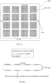
- FIG. 2A and FIG.2B illustrate an exemplary representation (Not to scale) of a top view and a side view, respectively of a metasurface 108 consisting of a periodic arrangement of unit cells according to some embodiments of the present disclosure.
- the dimensions illustrated are representative of an exemplary embodiment and ⁇ r represents relative permittivity while tan ⁇ represents dielectric loss tangent respectively.
- the metasurface 108 is square shaped.
- the optimized metasurface is finalized after performing many parametric iterations on the dimensions and number of unit cells.
- the MMW frequency antenna scanning system 100 comprises the two or more posts 110 having a first end and a second end, positioned on opposite sides of the first conducting plate 106, wherein the first end is coupled to the metasurface 108, and configured to have vertical movement along the Z-axis.
- the two or more posts 110 are made of an insulating material such as Polytetrafluoroethylene (PTFE), Bakelite, and the like.
- PTFE Polytetrafluoroethylene
- the first end of each post is coupled to a midpoint of opposite sides of the metasurface.
- the first end of each post is coupled to a midpoint of each side of the metasurface.
- the MMW frequency antenna scanning system 100 further comprises a controller unit 112 that is in communication with the two or more posts 110 via the second end of the two or more posts.
- the controller unit 112 comprises two or more motors 112A, wherein each of the two or more motors 112A are configured to independently control the vertical movement of an associated post from the two or more posts 110 along the Z-axis, such that the vertical movement results in a tilt of the connected metasurface 108 with reference to an orientation of the microstrip antenna 102.
- the two or more motors 112A are Direct Current (DC) motors such as stepper motors.
- DC Direct Current
- the controller unit 112 further comprises one or more data storage devices or memory 112B configured to store instructions; one or more communication interfaces 112C; and one or more hardware processors 112D operatively coupled to the one or more data storage devices via the one or more communication interfaces 112C, wherein the one or more hardware processors 112D are configured by the instructions to perform beam steering.
- the one or more hardware processors 112D can be implemented as one or more microprocessors, microcomputers, microcontrollers, digital signal processors, central processing units, state machines, graphics controllers, logic circuitries, and/or any devices that manipulate signals based on operational instructions.
- the processor(s) are configured to fetch and execute computer-readable instructions stored in the memory.
- the expressions 'processors' and ⁇ hardware processors' may be used interchangeably.
- the one or more hardware processors 112D can be implemented in a variety of computing systems, such as laptop computers, notebooks, hand-held devices, workstations, mainframe computers, servers, a network cloud and the like.
- the communication interface(s) or input/output (I/O) interface(s) 112C may include a variety of software and hardware interfaces, for example, a web interface, a graphical user interface, and the like and can facilitate multiple communications within a wide variety of networks N/W and protocol types, including wired networks, for example, LAN, cable, etc., and wireless networks, such as WLAN, cellular, or satellite.
- the I/O interface(s) can include one or more ports for connecting a number of devices to one another or to another server.
- the one or more data storage devices or memory 112B may include any computer-readable medium known in the art including, for example, volatile memory, such as static random access memory (SRAM) and dynamic random access memory (DRAM), and/or non-volatile memory, such as read only memory (ROM), erasable programmable ROM, flash memories, hard disks, optical disks, and magnetic tapes.
- volatile memory such as static random access memory (SRAM) and dynamic random access memory (DRAM)
- DRAM dynamic random access memory
- non-volatile memory such as read only memory (ROM), erasable programmable ROM, flash memories, hard disks, optical disks, and magnetic tapes.
- the one or more hardware processors 112D are configured to generate a driving voltage for synchronously controlling the two or more motors 112A such that the coupled metasurface 108 tilts with reference to the orientation of the microstrip antenna 102 by an inclination angle for beam steering that provides a predetermined directivity to the microstrip antenna, wherein the beam steering involves steering of beams of the radio waves.
- the predetermined directivity degree to which the radio wave is transmitted/received is concentrated in a single direction
- the inclination angle is identical to an angle of tilt ⁇ of a main lobe of a transmitted or received radio waves from the microstrip antenna 102.
- the first predetermined distance and the second predetermined distance are optimized based on impedance matching, radiation gain and accuracy of the beam steering.
- the antenna's input impedance matching with corresponding RF circuitry's output impedance is critical to minimize reflection of the radio waves or maximize power transfer. Best performance may be assessed empirically and accordingly the first predetermined distance and the second predetermined distance may be determined.
- the first predetermined distance is based on domain knowledge pertaining to cavity antenna. Accordingly, the first predetermined distance is based on a wavelength ( ⁇ ) corresponding to a frequency of operation. In an embodiment, for the frequency of operation 28GHz, ⁇ is 10.7mm. The first predetermined distance is an odd multiple of ⁇ /4, for instance, 3 ⁇ /4 or 5 ⁇ /4, and the like.
- the second predetermined distance is empirically determined as 8millimeter (mm). This is further explained under Experimental evaluation with reference to Table 2 later in the description.
- FIG. 3A and FIG.3B illustrate an exemplary representation (Not to scale) of a top view and a side view, respectively of a microstrip antenna 102 in accordance with some embodiments of the present disclosure.
- the dimensions illustrated are representative of an exemplary embodiment and ⁇ r represents relative permittivity while tan ⁇ represents dielectric loss tangent respectively.
- the microstrip antenna 102 is characterized by a substrate 102A that accommodates a radiating patch 102B on a first surface and a second conducting plate 114 on an opposite surface.
- the radiating patch 102B is copper material.
- a predefined region 102C separates sides of the radiating patch 102B from the sides of the substrate 102A.
- a feed point 102D is disposed at an empirically determined position (e.g. 1.2, -1, 0.787mm) in the radiating patch 102B.
- a shorting pin 102E is disposed at an empirically determined position (e.g. 2.2, -2.5, 0.787mm) in a portion of the radiating patch 102B that extends into the predefined region 102C.
- the feed point 102D and the shorting pin 102E may have the same diameter (e.g. 0.8mm).
- FIG.4A through FIG.4B is an exemplary flow diagram illustrating a computer implemented method for beam steering of a Millimeter Wave (MMW) frequency antenna scanning system, in accordance with an embodiment of the present disclosure.
- the steps of the method 200 will now be explained in detail with reference to the components of the system 100 of FIG.1 .
- process steps, method steps, techniques or the like may be described in a sequential order, such processes, methods and techniques may be configured to work in alternate orders.
- any sequence or order of steps that may be described does not necessarily indicate a requirement that the steps be performed in that order.
- the steps of processes described herein may be performed in any order practical. Further, some steps may be performed simultaneously.
- the method 200 comprises, positioning the microstrip antenna 102 horizontally, in an XY plane of a Cartesian coordinate system, at step 202, such that the microstrip antenna 102 cooperates with a Radio Frequency (RF) chain 104 of the system 100 to receive and transmit the radio waves.
- the first conducting plate 106 is positioned at the first predetermined distance from the microstrip antenna 102, at step 204, wherein the first conducting plate 106 is connected to the ground terminal and configured to reflect the radio waves.
- the metasurface 108 is disposed, at step 206, such that the center point of the metasurface 108 is at the second predetermined distance, along the Z-axis in the Cartesian coordinate system, from the radiating face of the microstrip antenna 102.
- the two or more posts 110 having the first end and the second end, on opposite sides of the first conducting plate 106, are positioned at step 208, wherein the first end is coupled to the metasurface 108, and configured to have vertical movement along the Z-axis.
- the driving voltage is then generated, at step 210, by the controller unit 112 for synchronously controlling the two or more motors 112A, wherein each of the two or more motors are configured to independently control the vertical movement of an associated post from the two or more posts 110 along the Z-axis.
- Beam steering is performed, at step 212, by the vertical movement that results in a tilt of the coupled metasurface 108 with reference to an orientation of the microstrip antenna 102 by an inclination angle, to achieve a predetermined directivity associated with the microstrip antenna 102, wherein the beam steering involves steering of beams of the radio waves.
- Table 2 below shows beam steering characteristics of the MMW frequency antenna scanning system 100 for various values of separation between the metasurface 108 and the microstrip antenna 102 represented by the second predetermined distance I.
- the angle rotate represents the inclination angle of the metasurface 108 with respect to the horizontally placed microstrip antenna 102.
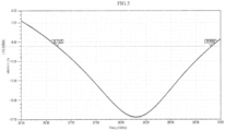
- FIG.5 is a Reflection Coefficient (S11) curve that illustrates broadband impedance matching (S11 below -10 dB) characteristics of the microstrip antenna 102 in MMW frequency range. From FIG.5 , it may be noted that the S11 is below -10 dB over the span of 26.73-29.80 GHz with a resonant frequency of 28.3 GHz. The value of S11 even at 28 GHz is below -15dB.
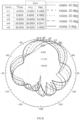
- FIG.6 is a 2-Dimensional radiation pattern of the microstrip antenna 102 according to some embodiments of the present disclosure.
- Radiation gain of the microstrip antenna 102 placed horizontally in the x-y plane has been depicted as a function of the angle tilt ⁇ of the main lobe of the transmitted or received radio waves from the microstrip antenna 102.
- the radiation pattern has been plotted for both ⁇ equals 0° and 90° plane.
- the spherical coordinates are:
- the numerical values distributed over the outermost circle represents the angle ⁇ and the numerical values (vertically arranged) mentioned at the circumference of each inner circle represent the radiation gain value in dB. It may be noted from FIG.6 that the microstrip antenna 102 of the present disclosure radiates near omnidirectional pattern (@ frequency 28 GHz) having a good gain (gain is about 3.76 dB for angle of tilt ⁇ of the main lobe of a transmitted beam equals 0°).
- FIG.7 illustrates the S11 plots for the microstrip antenna 102 having various values of inclination angle of the metasurface 108, according to some embodiments of the present disclosure. It may be noted that the impedance matching is good (S11 below -15 dB) for each value of inclination angle.
- FIG.8 is a 2-Dimensional radiation pattern of the microstrip antenna 102 for various values of inclination angle of the metasurface 108, according to some embodiments of the present disclosure.
- the expressions 'ang' and 'mag' depicted in the figure represent angle and magnitude respectively, associated with the gain in the radiation pattern plot.
- Markers m1, m2, m3, m4 and m5 correspond to mark the peak of main beam for the inclination angle 0°, 10°, 20°, 30° and 40° respectively.
- the second predetermined distance between the microstrip antenna 102 and the metasurface 108 is fixed at 8 mm irrespective of the inclination angle.
- the peak beam got steered w.r.t the reference beam with the same angle (30°) as that of the metasurface inclination angle.
- the peak beam got steered w.r.t the reference beam with the same angle (40°) as that of the metasurface inclination angle.
- the main beam is getting steered with the same angle as that of metasurface inclination angle.
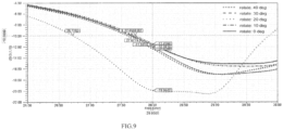
- FIG.9 illustrates the S11 plots for the microstrip antenna 102 having various values of inclination angle of metasurface, when the metasurface is disposed at a distance of 4millimeter(mm) from a radiating face of the microstrip antenna, according to some embodiments of the present disclosure.
- S11 lies between -10 dB and -15 dB at frequency of interest 28 GHz for various inclination angles of the metasurface 108, which does not match the requirement (S11 ⁇ -15dB as desired in MMW applications). Considering this requirement, the S11 dip illustrates not a good matching except for inclination angle of 20°.
- FIG. 10 is a 2-Dimensional radiation pattern of the microstrip antenna 102 for various values of inclination angle of metasurface, when the metasurface 108 is disposed at a distance of 4millimeter(mm) from the radiating face of the microstrip antenna 102, according to some embodiments of the present disclosure.
- the expressions 'ang' and 'mag' depicted in the figure represent angle and magnitude respectively, associated with the gain in the radiation pattern plot.
- the peak points of the radiation pattern have been marked by markers m1, m2, m3 and m4. It has been observed that the two peak points, corresponding to the radiation pattern for inclination angle 10° and 20°, coincided at the same point marked by m2. Also, the rest of the beam are not getting steered in a good manner as expected.
- the separation between antenna and metasurface was optimized to get the S11 dip (@ 28 GHz) below -15 dB for every inclination angle of the metasurface 108. Also, the beam needs to get steered with the same angle as that of angle rotate.
- the optimized second predetermined distance which fulfills both these criteria is 8 mm.
- the computer controlled electromechanical system 100 thus provides a cost effective and compact MMW frequency antenna scanning system with desired beam steering
- Such computer-readable storage means contain program-code means for implementation of one or more steps of the method, when the program runs on a server or mobile device or any suitable programmable device.
- the hardware device can be any kind of device which can be programmed including e.g., any kind of computer like a server or a personal computer, or the like, or any combination thereof.
- the device may also include means which could be e.g., hardware means like e.g., an application-specific integrated circuit (ASIC), a field-programmable gate array (FPGA), or a combination of hardware and software means, e.g., an ASIC and an FPGA, or at least one microprocessor and at least one memory with software processing components located therein.
- the means can include both hardware means and software means.
- the method embodiments described herein could be implemented in hardware and software.
- the device may also include software means. Alternatively, the embodiments may be implemented on different hardware devices, e.g., using a plurality of CPUs.
- the embodiments herein can comprise hardware and software elements.
- the embodiments that are implemented in software include but are not limited to, firmware, resident software, microcode, etc.
- the functions performed by various components described herein may be implemented in other components or combinations of other components.
- a computer-usable or computer readable medium can be any apparatus that can comprise, store, communicate, propagate, or transport the program for use by or in connection with the instruction execution system, apparatus, or device.
- a computer-readable storage medium refers to any type of physical memory on which information or data readable by a processor may be stored.
- a computer-readable storage medium may store instructions for execution by one or more processors, including instructions for causing the processor(s) to perform steps or stages consistent with the embodiments described herein.
- the term "computer-readable medium” should be understood to include tangible items and exclude carrier waves and transient signals, i.e., be non-transitory. Examples include random access memory (RAM), read-only memory (ROM), volatile memory, nonvolatile memory, hard drives, CD ROMs, DVDs, flash drives, disks, and any other known physical storage media.
Landscapes
- Physics & Mathematics (AREA)
- Optics & Photonics (AREA)
- Variable-Direction Aerials And Aerial Arrays (AREA)
- Waveguide Aerials (AREA)
Claims (12)
- Millimeterwellen-, MMW-, Frequenzantennenabtastsystem (100), umfassend:eine Mikrostreifenantenne (102), die horizontal in einer XY-Ebene eines kartesischen Koordinatensystems positioniert ist, wobei die Mikrostreifenantenne (102) konfiguriert ist, um mit einer Hochfrequenz-, RF-, Kette (104) zusammenzuwirken, um eine oder mehrere Funkwellen zu empfangen und zu senden;eine erste leitende Platte (106), die in einem ersten vorbestimmten Abstand von der Mikrostreifenantenne (102) entlang einer Z-Achse in dem kartesischen Koordinatensystem positioniert ist, wobei der erste vorbestimmte Abstand auf einer Wellenlänge, λ, basiert, die einer Betriebsfrequenz der Mikrostreifenantenne (102) entspricht, sodass der erste vorbestimmte Abstand ein ungeradzahliges Vielfaches von λ/4 ist, und wobei die erste leitende Platte (106) mit einem Masseanschluss verbunden und konfiguriert ist, um die eine oder mehreren Funkwellen zu reflektieren;eine Metafläche (108), die so angeordnet ist, dass sich ein Mittelpunkt davon in einem zweiten vorbestimmten Abstand entlang der Z-Achse in dem kartesischen Koordinatensystem von einer Strahlungsfläche der Mikrostreifenantenne (102) befindet;zwei oder mehr Pfosten (110) mit einem ersten Ende und einem zweiten Ende, die auf gegenüberliegenden Seiten der ersten leitenden Platte (106) positioniert sind, wobei das erste Ende mit der Metafläche (108) gekoppelt ist, wobei die zwei oder mehr Pfosten (110) konfiguriert sind, um eine vertikale Bewegung entlang der Z-Achse in dem kartesischen Koordinatensystem aufzuweisen; undeine Steuereinheit (112) in Kommunikation mit den zwei oder mehr Pfosten 110 über das zweite Ende davon, wobei die Steuereinheit (112) Folgendes umfasst:zwei oder mehr Motoren (112A), wobei jeder der zwei oder mehr Motoren (112A) konfiguriert ist, um die vertikale Bewegung eines zugehörigen Pfostens von den zwei oder mehr Pfosten (110) entlang der Z-Achse unabhängig zu steuern, sodass die vertikale Bewegung zu einer Neigung der verbundenen Metafläche (108) in Bezug auf eine Ausrichtung der Mikrostreifenantenne (102) führt; undeine oder mehrere Datenspeichervorrichtungen (112B), die konfiguriert sind, um Anweisungen zu speichern;eine oder mehrere Kommunikationsschnittstellen (112C); undeinen oder mehrere Hardwareprozessoren (112D), die mit der einen oder den mehreren Datenspeichervorrichtungen (112B) über die eine oder die mehreren Kommunikationsschnittstellen (112C) wirkgekoppelt sind, wobei der eine oder die mehreren Hardwareprozessoren (112D) durch die Anweisungen konfiguriert sind zum:
Erzeugen einer Antriebsspannung zum synchronen Steuern der zwei oder mehr Motoren (112A), sodass die gekoppelte Metafläche (108) in Bezug auf die Ausrichtung der Mikrostreifenantenne (102) um einen Neigungswinkel zur Strahllenkung neigt, der eine vorbestimmte Richtwirkung für die Mikrostreifenantenne (102) bereitstellt, wobei die Strahllenkung das Lenken von Strahlen der einen oder mehreren Funkwellen beinhaltet. - MMW-Frequenzantennenabtastsystem (100) nach Anspruch 1, wobei der erste vorbestimmte Abstand und der zweite vorbestimmte Abstand basierend auf Impedanzanpassung, Strahlungsgewinn und Genauigkeit der Strahllenkung optimiert sind.
- MMW-Frequenzantennenabtastsystem (100) nach Anspruch 1, wobei der zweite vorbestimmte Abstand 8 Millimeter, mm, beträgt.
- MMW-Frequenzantennenabtastsystem (100) nach Anspruch 1, wobei der Neigungswinkel mit einem Neigungswinkel θ einer Hauptkeule einer gesendeten oder empfangenen Funkwelle von der Mikrostreifenantenne (102) identisch ist.
- MMW-Frequenzantennenabtastsystem (100) nach Anspruch 1, wobei die Metafläche (108) quadratisch geformt ist.
- MMW-Frequenzantennenabtastsystem (100) nach Anspruch 1, wobei die Mikrostreifenantenne (102) gekennzeichnet ist durch:ein Substrat (102A), das einen Strahlungsfleck (102B) auf einer ersten Oberfläche und eine zweite leitende Platte (114) auf einer gegenüberliegenden Oberfläche aufnimmt;Seiten des Strahlungsflecks (102B) und Seiten des Substrats (102A) durch einen vordefinierten Bereich (102C) getrennt sind;einen Abschnitt einer Seite des Strahlungsflecks (102B) in der Nähe einer Ecke des Strahlungsflecks (102B) und sich in den vordefinierten Bereich (102C) entlang zweier benachbarter Seiten des Substrats (102A) in der Nähe der Ecke erstreckt;einen Speisepunkt (102D), der an einer empirisch bestimmten Position in dem Strahlungsfleck (102B) angeordnet ist; undeinen Kurzschlussstift (102E), der an einer empirisch bestimmten Position in einem Abschnitt des Strahlungsflecks (102B) angeordnet ist, der sich in den vordefinierten Bereich (102C) erstreckt.
- MMW-Frequenzantennenabtastsystem (100) nach Anspruch 6, wobei das Substrat (102A) quadratisch geformt ist und der Strahlungsfleck (102B) rechteckig geformt ist.
- MMW-Frequenzantennenabtastsystem (100) nach Anspruch 1, wobei die zwei oder mehr Motoren Schrittmotoren sind.
- Prozessorimplementiertes Verfahren (200), umfassend:Positionieren (202) einer Mikrostreifenantenne (102) horizontal in einer XY-Ebene eines kartesischen Koordinatensystems und Zusammenwirken mit einer Hochfrequenz-, RF-, Kette (104), um eine oder mehrere Funkwellen zu empfangen und zu senden;Positionieren (204) einer ersten leitenden Platte (106) in einem ersten vorbestimmten Abstand von der Mikrostreifenantenne (102) entlang einer Z-Achse in dem kartesischen Koordinatensystem, wobei der erste vorbestimmte Abstand auf einer Wellenlänge, λ, basiert, die einer Betriebsfrequenz der Mikrostreifenantenne (102) entspricht, sodass der erste vorbestimmte Abstand ein ungeradzahliges Vielfaches von λ/4 ist, und wobei die erste leitende Platte (106) mit einem Masseanschluss verbunden und konfiguriert ist, um die eine oder mehreren Funkwellen zu reflektieren;Anordnen (206) einer Metafläche (108), sodass sich ein Mittelpunkt davon in einem zweiten vorbestimmten Abstand entlang der Z-Achse in dem kartesischen Koordinatensystem von einer Strahlungsfläche der Mikrostreifenantenne (102) befindet;Positionieren (208) von zwei oder mehr Pfosten (110) mit einem ersten Ende und einem zweiten Ende auf gegenüberliegenden Seiten der ersten leitenden Platte (106), wobei das erste Ende mit der Metafläche (108) gekoppelt ist, wobei die zwei oder mehr Pfosten (110) konfiguriert sind, um eine vertikale Bewegung entlang der Z-Achse in dem kartesischen Koordinatensystem aufzuweisen;Erzeugen (210) einer Antriebsspannung durch eine Steuereinheit (112) zum synchronen Steuern von zwei oder mehr Motoren (112A), wobei jeder der zwei oder mehr Motoren konfiguriert ist, um die vertikale Bewegung eines zugehörigen Pfostens von den zwei oder mehr Pfosten (110) entlang der Z-Achse unabhängig zu steuern; undDurchführen (212) einer Strahllenkung durch die vertikale Bewegung, die zu einer Neigung der gekoppelten Metafläche (108) in Bezug auf eine Ausrichtung der Mikrostreifenantenne (102) um einen Neigungswinkel führt, um eine vorbestimmte Richtwirkung zu erreichen, die der Mikrostreifenantenne (102) zugeordnet ist, wobei die Strahllenkung das Lenken von Strahlen der einen oder mehreren Funkwellen beinhaltet.
- Prozessorimplementiertes Verfahren (200) nach Anspruch 9, wobei der erste vorbestimmte Abstand und der zweite vorbestimmte Abstand basierend auf einer Impedanzanpassung, einem Strahlungsgewinn und einer Genauigkeit der Strahllenkung optimiert sind.
- Prozessorimplementiertes Verfahren (200) nach Anspruch 9, wobei der zweite vorbestimmte Abstand 8 Millimeter, mm, beträgt.
- Prozessorimplementiertes Verfahren (200) nach Anspruch 9, wobei der Neigungswinkel mit einem Neigungswinkel θ einer Hauptkeule einer gesendeten oder empfangenen Funkwelle von der Mikrostreifenantenne (102) identisch ist.
Applications Claiming Priority (1)
| Application Number | Priority Date | Filing Date | Title |
|---|---|---|---|
| IN202121023515 | 2021-05-27 |
Publications (3)
| Publication Number | Publication Date |
|---|---|
| EP4096022A1 EP4096022A1 (de) | 2022-11-30 |
| EP4096022B1 true EP4096022B1 (de) | 2024-08-07 |
| EP4096022C0 EP4096022C0 (de) | 2024-08-07 |
Family
ID=81648049
Family Applications (1)
| Application Number | Title | Priority Date | Filing Date |
|---|---|---|---|
| EP22172871.0A Active EP4096022B1 (de) | 2021-05-27 | 2022-05-24 | Computergesteuertes elektromechanisches mmw-frequenz-antennenabtastsystem und dessen strahlsteuerung |
Country Status (2)
| Country | Link |
|---|---|
| US (1) | US11990685B2 (de) |
| EP (1) | EP4096022B1 (de) |
Family Cites Families (9)
| Publication number | Priority date | Publication date | Assignee | Title |
|---|---|---|---|---|
| JP3186622B2 (ja) * | 1997-01-07 | 2001-07-11 | 株式会社村田製作所 | アンテナ装置および送受信装置 |
| US6812903B1 (en) * | 2000-03-14 | 2004-11-02 | Hrl Laboratories, Llc | Radio frequency aperture |
| JP4456998B2 (ja) * | 2004-12-28 | 2010-04-28 | 日立オートモティブシステムズ株式会社 | 速度センサおよびそれを用いた対地車速センサ |
| US9972906B2 (en) | 2015-01-15 | 2018-05-15 | Outthink Technologies, Llc | Two-way antenna mounting bracket and assembly with independently adjustable electromechanical antenna tilt and azimuthal steering for beam reshaping |
| WO2017091845A1 (en) * | 2015-12-01 | 2017-06-08 | Macquarie University | A directional antenna with a variable beam direction |
| US11342682B2 (en) * | 2018-05-24 | 2022-05-24 | Metawave Corporation | Frequency-selective reflector module and system |
| KR102745866B1 (ko) * | 2019-06-28 | 2024-12-23 | 삼성전자주식회사 | 안테나 구조 및 이를 포함하는 전자 장치 |
| EP4088343A4 (de) * | 2020-01-08 | 2024-01-17 | Metawave Corporation | Reflektorantenne mit zweidimensionaler strahlabtastung |
| US12218426B2 (en) * | 2020-12-10 | 2025-02-04 | Intel Corporation | Low-profile single-chain beam-steerable MMW lens antenna |
-
2022
- 2022-05-13 US US17/663,241 patent/US11990685B2/en active Active
- 2022-05-24 EP EP22172871.0A patent/EP4096022B1/de active Active
Also Published As
| Publication number | Publication date |
|---|---|
| US20230006346A1 (en) | 2023-01-05 |
| US11990685B2 (en) | 2024-05-21 |
| EP4096022C0 (de) | 2024-08-07 |
| EP4096022A1 (de) | 2022-11-30 |
Similar Documents
| Publication | Publication Date | Title |
|---|---|---|
| Federico et al. | A review of antenna array technologies for point‐to‐point and point‐to‐multipoint wireless communications at millimeter‐wave frequencies | |
| EP3320580B1 (de) | Metamaterial-basiertes sendearray für mehrstrahl-antennenarrayanordnungen | |
| Zhu et al. | Mechanically pattern reconfigurable antenna using metasurface | |
| Ray et al. | Two-pair slots inserted CP patch antenna for wide axial ratio beamwidth | |
| Kim et al. | Electromagnetic band gap‐dipole sub‐array antennas creating an enhanced tilted beams for future base station | |
| CN113437492A (zh) | 通信装置、毫米波全息天线及其制造方法 | |
| Dadgarpour et al. | High‐gain end‐fire bow‐tie antenna using artificial dielectric layers | |
| Pu et al. | Miniaturized wideband quadrifilar helix antenna for satellite navigation application | |
| Raj et al. | Design and Analysis of Sierpinski Fractal Antennas for Millimeter‐Wave 5G and Ground‐Based Radio Navigation Applications | |
| Xie et al. | Wide‐angle scanning circular polarization phased array based on polarization rotation technology | |
| Zheng et al. | A wide‐angle scanning Luneburg lens antenna | |
| Rahmani et al. | Pattern Reconfigurable Antenna for VANET, Wi‐Fi, and WiMAX Wireless Communication Systems | |
| Kamran Saleem et al. | Switched beam dielectric resonator antenna array with six reconfigurable radiation patterns | |
| EP4096022B1 (de) | Computergesteuertes elektromechanisches mmw-frequenz-antennenabtastsystem und dessen strahlsteuerung | |
| US12394895B2 (en) | Meta-antenna for 6th generation network passive beam-forming and method therefor | |
| US12283756B2 (en) | Antenna array element with dual polarization, antenna array including antenna array element and electronic device including antenna array | |
| Ghosh et al. | Dual‐port circular patch antenna array: Enhancing gain and minimizing cross‐polarization for mm‐wave 5G networks | |
| Saleem et al. | Integrated lens antenna array with full azimuth plane beam scanning capability at 60 GHz | |
| Mohammadirad et al. | Phase error analysis of the effect of feed movement on bandwidth performance of a broadband X‐Ku band reflectarray | |
| Zhao et al. | A beamwidth and beam direction reconfigurable antenna based on multi‐mode parasitic coupling | |
| Lee et al. | A mechanically pattern reconfigurable array | |
| Meredov et al. | 77 GHz screen printed, flexible, beam-switching antenna array for wearable radar applications | |
| RU2795571C1 (ru) | Двухполяризационная антенная решетка с широким углом сканирования | |
| EP4307477B1 (de) | Multifunktionales meta-oberflächen-koplanarantennensystem mit mehreren anschlüssen zur strahlschwenkungssteuerung | |
| Roy et al. | Single Feed Based Wide Band Circularly Polarized Radiating Element For S-band SATCOM |
Legal Events
| Date | Code | Title | Description |
|---|---|---|---|
| PUAI | Public reference made under article 153(3) epc to a published international application that has entered the european phase |
Free format text: ORIGINAL CODE: 0009012 |
|
| STAA | Information on the status of an ep patent application or granted ep patent |
Free format text: STATUS: THE APPLICATION HAS BEEN PUBLISHED |
|
| AK | Designated contracting states |
Kind code of ref document: A1 Designated state(s): AL AT BE BG CH CY CZ DE DK EE ES FI FR GB GR HR HU IE IS IT LI LT LU LV MC MK MT NL NO PL PT RO RS SE SI SK SM TR |
|
| STAA | Information on the status of an ep patent application or granted ep patent |
Free format text: STATUS: REQUEST FOR EXAMINATION WAS MADE |
|
| 17P | Request for examination filed |
Effective date: 20221216 |
|
| RBV | Designated contracting states (corrected) |
Designated state(s): AL AT BE BG CH CY CZ DE DK EE ES FI FR GB GR HR HU IE IS IT LI LT LU LV MC MK MT NL NO PL PT RO RS SE SI SK SM TR |
|
| GRAP | Despatch of communication of intention to grant a patent |
Free format text: ORIGINAL CODE: EPIDOSNIGR1 |
|
| STAA | Information on the status of an ep patent application or granted ep patent |
Free format text: STATUS: GRANT OF PATENT IS INTENDED |
|
| GRAS | Grant fee paid |
Free format text: ORIGINAL CODE: EPIDOSNIGR3 |
|
| INTG | Intention to grant announced |
Effective date: 20240607 |
|
| GRAA | (expected) grant |
Free format text: ORIGINAL CODE: 0009210 |
|
| STAA | Information on the status of an ep patent application or granted ep patent |
Free format text: STATUS: THE PATENT HAS BEEN GRANTED |
|
| AK | Designated contracting states |
Kind code of ref document: B1 Designated state(s): AL AT BE BG CH CY CZ DE DK EE ES FI FR GB GR HR HU IE IS IT LI LT LU LV MC MK MT NL NO PL PT RO RS SE SI SK SM TR |
|
| REG | Reference to a national code |
Ref country code: GB Ref legal event code: FG4D |
|
| REG | Reference to a national code |
Ref country code: CH Ref legal event code: EP |
|
| REG | Reference to a national code |
Ref country code: DE Ref legal event code: R096 Ref document number: 602022005087 Country of ref document: DE |
|
| REG | Reference to a national code |
Ref country code: IE Ref legal event code: FG4D |
|
| U01 | Request for unitary effect filed |
Effective date: 20240807 |
|
| U07 | Unitary effect registered |
Designated state(s): AT BE BG DE DK EE FI FR IT LT LU LV MT NL PT SE SI Effective date: 20240819 |
|
| PG25 | Lapsed in a contracting state [announced via postgrant information from national office to epo] |
Ref country code: NO Free format text: LAPSE BECAUSE OF FAILURE TO SUBMIT A TRANSLATION OF THE DESCRIPTION OR TO PAY THE FEE WITHIN THE PRESCRIBED TIME-LIMIT Effective date: 20241107 |
|
| PG25 | Lapsed in a contracting state [announced via postgrant information from national office to epo] |
Ref country code: PL Free format text: LAPSE BECAUSE OF FAILURE TO SUBMIT A TRANSLATION OF THE DESCRIPTION OR TO PAY THE FEE WITHIN THE PRESCRIBED TIME-LIMIT Effective date: 20240807 Ref country code: GR Free format text: LAPSE BECAUSE OF FAILURE TO SUBMIT A TRANSLATION OF THE DESCRIPTION OR TO PAY THE FEE WITHIN THE PRESCRIBED TIME-LIMIT Effective date: 20241108 |
|
| PG25 | Lapsed in a contracting state [announced via postgrant information from national office to epo] |
Ref country code: IS Free format text: LAPSE BECAUSE OF FAILURE TO SUBMIT A TRANSLATION OF THE DESCRIPTION OR TO PAY THE FEE WITHIN THE PRESCRIBED TIME-LIMIT Effective date: 20241207 |
|
| PG25 | Lapsed in a contracting state [announced via postgrant information from national office to epo] |
Ref country code: HR Free format text: LAPSE BECAUSE OF FAILURE TO SUBMIT A TRANSLATION OF THE DESCRIPTION OR TO PAY THE FEE WITHIN THE PRESCRIBED TIME-LIMIT Effective date: 20240807 |
|
| PG25 | Lapsed in a contracting state [announced via postgrant information from national office to epo] |
Ref country code: RS Free format text: LAPSE BECAUSE OF FAILURE TO SUBMIT A TRANSLATION OF THE DESCRIPTION OR TO PAY THE FEE WITHIN THE PRESCRIBED TIME-LIMIT Effective date: 20241107 Ref country code: ES Free format text: LAPSE BECAUSE OF FAILURE TO SUBMIT A TRANSLATION OF THE DESCRIPTION OR TO PAY THE FEE WITHIN THE PRESCRIBED TIME-LIMIT Effective date: 20240807 |
|
| PG25 | Lapsed in a contracting state [announced via postgrant information from national office to epo] |
Ref country code: RS Free format text: LAPSE BECAUSE OF FAILURE TO SUBMIT A TRANSLATION OF THE DESCRIPTION OR TO PAY THE FEE WITHIN THE PRESCRIBED TIME-LIMIT Effective date: 20241107 Ref country code: PL Free format text: LAPSE BECAUSE OF FAILURE TO SUBMIT A TRANSLATION OF THE DESCRIPTION OR TO PAY THE FEE WITHIN THE PRESCRIBED TIME-LIMIT Effective date: 20240807 Ref country code: NO Free format text: LAPSE BECAUSE OF FAILURE TO SUBMIT A TRANSLATION OF THE DESCRIPTION OR TO PAY THE FEE WITHIN THE PRESCRIBED TIME-LIMIT Effective date: 20241107 Ref country code: IS Free format text: LAPSE BECAUSE OF FAILURE TO SUBMIT A TRANSLATION OF THE DESCRIPTION OR TO PAY THE FEE WITHIN THE PRESCRIBED TIME-LIMIT Effective date: 20241207 Ref country code: HR Free format text: LAPSE BECAUSE OF FAILURE TO SUBMIT A TRANSLATION OF THE DESCRIPTION OR TO PAY THE FEE WITHIN THE PRESCRIBED TIME-LIMIT Effective date: 20240807 Ref country code: GR Free format text: LAPSE BECAUSE OF FAILURE TO SUBMIT A TRANSLATION OF THE DESCRIPTION OR TO PAY THE FEE WITHIN THE PRESCRIBED TIME-LIMIT Effective date: 20241108 Ref country code: ES Free format text: LAPSE BECAUSE OF FAILURE TO SUBMIT A TRANSLATION OF THE DESCRIPTION OR TO PAY THE FEE WITHIN THE PRESCRIBED TIME-LIMIT Effective date: 20240807 |
|
| PG25 | Lapsed in a contracting state [announced via postgrant information from national office to epo] |
Ref country code: SM Free format text: LAPSE BECAUSE OF FAILURE TO SUBMIT A TRANSLATION OF THE DESCRIPTION OR TO PAY THE FEE WITHIN THE PRESCRIBED TIME-LIMIT Effective date: 20240807 |
|
| PG25 | Lapsed in a contracting state [announced via postgrant information from national office to epo] |
Ref country code: CZ Free format text: LAPSE BECAUSE OF FAILURE TO SUBMIT A TRANSLATION OF THE DESCRIPTION OR TO PAY THE FEE WITHIN THE PRESCRIBED TIME-LIMIT Effective date: 20240807 |
|
| PG25 | Lapsed in a contracting state [announced via postgrant information from national office to epo] |
Ref country code: SK Free format text: LAPSE BECAUSE OF FAILURE TO SUBMIT A TRANSLATION OF THE DESCRIPTION OR TO PAY THE FEE WITHIN THE PRESCRIBED TIME-LIMIT Effective date: 20240807 |
|
| PLBE | No opposition filed within time limit |
Free format text: ORIGINAL CODE: 0009261 |
|
| STAA | Information on the status of an ep patent application or granted ep patent |
Free format text: STATUS: NO OPPOSITION FILED WITHIN TIME LIMIT |
|
| U20 | Renewal fee for the european patent with unitary effect paid |
Year of fee payment: 4 Effective date: 20250526 |
|
| 26N | No opposition filed |
Effective date: 20250508 |
|
| PGFP | Annual fee paid to national office [announced via postgrant information from national office to epo] |
Ref country code: CH Payment date: 20250601 Year of fee payment: 4 |
|
| PG25 | Lapsed in a contracting state [announced via postgrant information from national office to epo] |
Ref country code: MC Free format text: LAPSE BECAUSE OF FAILURE TO SUBMIT A TRANSLATION OF THE DESCRIPTION OR TO PAY THE FEE WITHIN THE PRESCRIBED TIME-LIMIT Effective date: 20240807 |