EP4095644B1 - Verfahren zur flächenabdeckung mit nachfüllplaner - Google Patents
Verfahren zur flächenabdeckung mit nachfüllplaner Download PDFInfo
- Publication number
- EP4095644B1 EP4095644B1 EP22174233.1A EP22174233A EP4095644B1 EP 4095644 B1 EP4095644 B1 EP 4095644B1 EP 22174233 A EP22174233 A EP 22174233A EP 4095644 B1 EP4095644 B1 EP 4095644B1
- Authority
- EP
- European Patent Office
- Prior art keywords
- tracks
- autonomous vehicle
- trajectory
- track
- boundary
- Prior art date
- Legal status (The legal status is an assumption and is not a legal conclusion. Google has not performed a legal analysis and makes no representation as to the accuracy of the status listed.)
- Active
Links
Images


Classifications
-
- G—PHYSICS
- G05—CONTROLLING; REGULATING
- G05D—SYSTEMS FOR CONTROLLING OR REGULATING NON-ELECTRIC VARIABLES
- G05D1/00—Control of position, course, altitude or attitude of land, water, air or space vehicles, e.g. using automatic pilots
- G05D1/02—Control of position or course in two dimensions
- G05D1/021—Control of position or course in two dimensions specially adapted to land vehicles
- G05D1/0212—Control of position or course in two dimensions specially adapted to land vehicles with means for defining a desired trajectory
- G05D1/0217—Control of position or course in two dimensions specially adapted to land vehicles with means for defining a desired trajectory in accordance with energy consumption, time reduction or distance reduction criteria
-
- G—PHYSICS
- G05—CONTROLLING; REGULATING
- G05D—SYSTEMS FOR CONTROLLING OR REGULATING NON-ELECTRIC VARIABLES
- G05D1/00—Control of position, course, altitude or attitude of land, water, air or space vehicles, e.g. using automatic pilots
- G05D1/02—Control of position or course in two dimensions
- G05D1/021—Control of position or course in two dimensions specially adapted to land vehicles
- G05D1/0212—Control of position or course in two dimensions specially adapted to land vehicles with means for defining a desired trajectory
- G05D1/0219—Control of position or course in two dimensions specially adapted to land vehicles with means for defining a desired trajectory ensuring the processing of the whole working surface
-
- G—PHYSICS
- G01—MEASURING; TESTING
- G01C—MEASURING DISTANCES, LEVELS OR BEARINGS; SURVEYING; NAVIGATION; GYROSCOPIC INSTRUMENTS; PHOTOGRAMMETRY OR VIDEOGRAMMETRY
- G01C21/00—Navigation; Navigational instruments not provided for in groups G01C1/00 - G01C19/00
- G01C21/26—Navigation; Navigational instruments not provided for in groups G01C1/00 - G01C19/00 specially adapted for navigation in a road network
- G01C21/34—Route searching; Route guidance
- G01C21/3407—Route searching; Route guidance specially adapted for specific applications
- G01C21/3423—Multimodal routing
-
- G—PHYSICS
- G01—MEASURING; TESTING
- G01C—MEASURING DISTANCES, LEVELS OR BEARINGS; SURVEYING; NAVIGATION; GYROSCOPIC INSTRUMENTS; PHOTOGRAMMETRY OR VIDEOGRAMMETRY
- G01C21/00—Navigation; Navigational instruments not provided for in groups G01C1/00 - G01C19/00
- G01C21/26—Navigation; Navigational instruments not provided for in groups G01C1/00 - G01C19/00 specially adapted for navigation in a road network
- G01C21/34—Route searching; Route guidance
- G01C21/3453—Special cost functions, i.e. other than distance or default speed limit of road segments
- G01C21/3461—Preferred or disfavoured areas, e.g. dangerous zones, toll or emission zones, intersections, manoeuvre types or segments such as motorways, toll roads or ferries
-
- G—PHYSICS
- G01—MEASURING; TESTING
- G01C—MEASURING DISTANCES, LEVELS OR BEARINGS; SURVEYING; NAVIGATION; GYROSCOPIC INSTRUMENTS; PHOTOGRAMMETRY OR VIDEOGRAMMETRY
- G01C21/00—Navigation; Navigational instruments not provided for in groups G01C1/00 - G01C19/00
- G01C21/38—Electronic maps specially adapted for navigation; Updating thereof
- G01C21/3804—Creation or updating of map data
- G01C21/3807—Creation or updating of map data characterised by the type of data
-
- G—PHYSICS
- G05—CONTROLLING; REGULATING
- G05D—SYSTEMS FOR CONTROLLING OR REGULATING NON-ELECTRIC VARIABLES
- G05D1/00—Control of position, course, altitude or attitude of land, water, air or space vehicles, e.g. using automatic pilots
- G05D1/02—Control of position or course in two dimensions
- G05D1/021—Control of position or course in two dimensions specially adapted to land vehicles
- G05D1/0212—Control of position or course in two dimensions specially adapted to land vehicles with means for defining a desired trajectory
- G05D1/0225—Control of position or course in two dimensions specially adapted to land vehicles with means for defining a desired trajectory involving docking at a fixed facility, e.g. base station or loading bay
-
- G—PHYSICS
- G05—CONTROLLING; REGULATING
- G05D—SYSTEMS FOR CONTROLLING OR REGULATING NON-ELECTRIC VARIABLES
- G05D1/00—Control of position, course, altitude or attitude of land, water, air or space vehicles, e.g. using automatic pilots
- G05D1/60—Intended control result
- G05D1/648—Performing a task within a working area or space, e.g. cleaning
-
- G—PHYSICS
- G05—CONTROLLING; REGULATING
- G05D—SYSTEMS FOR CONTROLLING OR REGULATING NON-ELECTRIC VARIABLES
- G05D1/00—Control of position, course, altitude or attitude of land, water, air or space vehicles, e.g. using automatic pilots
- G05D1/60—Intended control result
- G05D1/656—Interaction with payloads or external entities
- G05D1/661—Docking at a base station
-
- G—PHYSICS
- G06—COMPUTING OR CALCULATING; COUNTING
- G06Q—INFORMATION AND COMMUNICATION TECHNOLOGY [ICT] SPECIALLY ADAPTED FOR ADMINISTRATIVE, COMMERCIAL, FINANCIAL, MANAGERIAL OR SUPERVISORY PURPOSES; SYSTEMS OR METHODS SPECIALLY ADAPTED FOR ADMINISTRATIVE, COMMERCIAL, FINANCIAL, MANAGERIAL OR SUPERVISORY PURPOSES, NOT OTHERWISE PROVIDED FOR
- G06Q10/00—Administration; Management
- G06Q10/06—Resources, workflows, human or project management; Enterprise or organisation planning; Enterprise or organisation modelling
- G06Q10/063—Operations research, analysis or management
- G06Q10/0631—Resource planning, allocation, distributing or scheduling for enterprises or organisations
- G06Q10/06315—Needs-based resource requirements planning or analysis
-
- G—PHYSICS
- G06—COMPUTING OR CALCULATING; COUNTING
- G06Q—INFORMATION AND COMMUNICATION TECHNOLOGY [ICT] SPECIALLY ADAPTED FOR ADMINISTRATIVE, COMMERCIAL, FINANCIAL, MANAGERIAL OR SUPERVISORY PURPOSES; SYSTEMS OR METHODS SPECIALLY ADAPTED FOR ADMINISTRATIVE, COMMERCIAL, FINANCIAL, MANAGERIAL OR SUPERVISORY PURPOSES, NOT OTHERWISE PROVIDED FOR
- G06Q50/00—Information and communication technology [ICT] specially adapted for implementation of business processes of specific business sectors, e.g. utilities or tourism
- G06Q50/02—Agriculture; Fishing; Forestry; Mining
-
- A—HUMAN NECESSITIES
- A01—AGRICULTURE; FORESTRY; ANIMAL HUSBANDRY; HUNTING; TRAPPING; FISHING
- A01B—SOIL WORKING IN AGRICULTURE OR FORESTRY; PARTS, DETAILS, OR ACCESSORIES OF AGRICULTURAL MACHINES OR IMPLEMENTS, IN GENERAL
- A01B69/00—Steering of agricultural machines or implements; Guiding agricultural machines or implements on a desired track
- A01B69/007—Steering or guiding of agricultural vehicles, e.g. steering of the tractor to keep the plough in the furrow
- A01B69/008—Steering or guiding of agricultural vehicles, e.g. steering of the tractor to keep the plough in the furrow automatic
-
- A—HUMAN NECESSITIES
- A01—AGRICULTURE; FORESTRY; ANIMAL HUSBANDRY; HUNTING; TRAPPING; FISHING
- A01C—PLANTING; SOWING; FERTILISING
- A01C21/00—Methods of fertilising, sowing or planting
Definitions
- the present disclosure relates to area coverage planning with replenishment planning for an autonomous vehicle.
- Engineering vehicles such as tractors and compactors are widely used in agriculture and construction.
- a variety of farm implements may be towed behind or mounted on a tractor to perform various agricultural tasks, such as plowing, irrigation, fertilizer and pesticide spraying, seed spraying, harvesting, and the like.
- compactors may be used to create a level grade in construction projects.
- Autonomous or semi-autonomous vehicles are used for precision agriculture and construction.
- Various navigation planning algorithms can be used to guide an autonomous vehicle. There is a need for a coverage planner that can generate a coverage trajectory for an autonomous vehicle with an implement to traverse a work area in an efficient way.
- EP2984916 discloses a method for planning a path of an agricultural machine, wherein the agricultural machine traverses the path, wherein the agricultural machine executes a supply-based agricultural process in a working area of an agricultural field with an implement along the path, wherein the path comprises reset tours to reset a supply stock of the agricultural machine with a supply reset apparatus and wherein the path is determined according to a minimization of costs incurred by the reset tours.
- the path is determined by composing at least part of the path from pre-defined target tracks, that have been defined beforehand, which path is optimized according to at least one optimization criterion regarding the reset tours.
- the following variables are optimized: (1) the orientation (angle) of the tracks, (2) the order of tracks, and (3) the types of turns between tracks.
- the angle of the tracks relative to field boundaries influences the number and lengths of the machine tracks, the number of turns and the positions where the machine can be serviced.
- Track order and the type of turns are selected to achieve overall efficiency.
- the algorithm was tested by computing routes for a set of fields of different sizes and assuming different operations. On small fields that do not require servicing, optimizing the turns between tracks resulted in a reduction of up to 50 % in turning time compared to the prevailing practice of navigation between adjacent tracks. A comparison of two sprayers in terms of servicing efficiency suggested that the algorithm can help selecting machinery for given field geometries.
- JENSEN MARTIN F ET AL "Coverage planning for capacitated field operations, part II: Optimisation", BIOSYSTEMS ENGINEERING, ELSEVIER, AMSTERDAM, NL, vol. 139, 6 August 2015, pages 149-164 , discloses that capacitated field operations refer to the operations that involve material flow where there are capacity constraints to the load that the machine is able to carry.
- a capacitated operation cannot therefore be completed in one operation and the machine has to interrupt the operation, leave the field and travel to an out-of-field facility for refilling (or unloading) and to return back to the field to resume the operation.
- This paper develops an algorithmic approach for the optimisation of capacitated field operations using the case of liquid fertilising.
- the approach is based on the state-space search technique where a solution is a sequence of pre-defined driving actions which are applied to the initial state that transform it to a goal state under the criterion of the minimisation of the non-productive travelled distance.
- the sequence of the working tracks is optimised in a post-process stage where the nonproductive travelled distance in headland turnings is further minimised by implementing the travelling salesman problem methodology.
- three fertilising operations were recorded and the optimised plans were compared to the conventional plans followed during the operations. Savings in the non-productive travelled distance was 15.7 %-43.5 %, while savings in the total travelled distance was 5.8 %-11.8 %.
- WO 2018/055922 discloses a path creation unit capable of creating an autonomous work path where autonomous work is performed by a tractor within a work region that has been set in advance.
- a necessary material amount calculation unit calculates an estimated amount of fertilizer to be used by the tractor in the autonomous work path.
- a supply position setting unit sets a fertilizer supply position at a position outside the work region and designated by a user.
- a fertilizer remaining amount acquisition unit acquires a remaining amount of fertilizer that can be used by the tractor.
- a departure position setting unit sets a departure position to suspend the autonomous work and a return position to resume the same.
- the path creation unit is capable of creating a supply path from the departure position to the return position via the supply position.
- a method of area coverage planning for an autonomous vehicle includes, at a computer system, receiving information of a boundary of a work area and information of one or more obstacles located within the work area, and laying a plurality of tracks within the boundary of the work area.
- the plurality of tracks is spaced apart from each other by a spacing.
- Laying the plurality of tracks includes, based on (i) the information of the boundary of the work area, and (ii) the information of the one or more obstacles, performing a multivariate optimization to: (i) determine an optimal direction of the plurality of tracks, and (ii) an optimal offset for a first track from the boundary, so as to minimize a total distance of the plurality of tracks.
- the method further includes generating a trajectory that is traversable by the autonomous vehicle to traverse the plurality of tracks.
- a method of area coverage planning for an autonomous vehicle includes, at a computer system, receiving information of a boundary of a work area, and laying a plurality of tracks within the boundary of the work area.
- the plurality of tracks is spaced apart from each other by a spacing.
- Laying the plurality of tracks includes, based on the information of the boundary of the work area, performing a multivariate optimization to: (i) determine an optimal direction of the plurality of tracks, and (ii) an optimal offset for a first track from the boundary, so as to minimize a total distance of the plurality of tracks.
- the method further includes generating a trajectory that is traversable by the autonomous vehicle to traverse the plurality of tracks.
- a method of area coverage planning with replenishment planning for an autonomous vehicle includes, at a computer system, receiving information of a boundary of the work area, receiving location information of one or more refill stations for replenishing the material, and receiving information of a current amount of the material left in the autonomous vehicle.
- the method further includes, based on the information of the boundary of the work area, laying a plurality of tracks within the boundary of the work area so as to minimize a total distance of the plurality of tracks.
- the plurality of tracks is spaced apart from each other by a spacing.
- the method further includes generating a coverage trajectory that is traversable by the autonomous vehicle to traverse the plurality of tracks, and based on (i) the coverage trajectory, (ii) the location information of the one or more refill stations, (iii) the current amount of the material left in the autonomous vehicle, and (iv) a nominal full amount and a nominal consumption rate of the material by the autonomous vehicle, determining one or more logistic points along the coverage trajectory at which a remaining amount of the material reaches a threshold.
- the method further includes, for each respective logistic point of the one or more logistic points, generating a respective replenishment trajectory for the autonomous vehicle.
- the respective replenishment trajectory includes a first part from the respective logistic point to a respective refill station of the one of the one or more refill stations for replenishing the autonomous vehicle with the material, and a second part from the respective refill station to the respective logistic point for the autonomous vehicle to resume traversing the coverage trajectory.
- a method of area coverage planning with replenishment planning for an autonomous vehicle includes, at a computer system, receiving information of a boundary of the work area, receiving location information of one or more refill stations for replenishing the material, and receiving information of a current amount of the material left in the autonomous vehicle.
- the method further includes, based on the information of the boundary of the work area, laying a plurality of tracks within the boundary of the work area so as to minimize a total distance of the plurality of tracks.
- the plurality of tracks is spaced apart from each other by a spacing.
- the method further includes generating a coverage trajectory that is traversable by the autonomous vehicle to traverse the plurality of tracks, and based on (i) the coverage trajectory, (ii) the location information of the one or more refill stations, (iii) the current amount of the material left in the autonomous vehicle, and (iv) a nominal full amount and a nominal consumption rate of the material by the autonomous vehicle, determining one or more logistic points along the coverage trajectory at which the autonomous vehicle needs to be replenished with the material. Each respective logistic point is at an end of a respective track.
- the method further includes, for each respective logistic point of the one or more logistic points, generating a respective replenishment trajectory for the autonomous vehicle.
- the respective replenishment trajectory includes a first part from the respective logistic point to a respective refill station of the one of the one or more refill stations for replenishing the autonomous vehicle with the material, and a second part from the respective refill station to a beginning of a next track for the autonomous vehicle to resume traversing the coverage trajectory.
- an area coverage planner can automatically generate a single trajectory for guiding an autonomous vehicle across the work area, so as to maximize coverage while minimizing the total distance travelled and the total duration of time, thus saving fuel and resources.
- the boundary can have irregular shapes, and can have convex as well as concave sections.
- the area coverage planner can accommodate static obstacles, such as electrical poles, located inside the boundary so that the trajectory avoids the static obstacles.
- the area coverage planner can optimize the layout of tracks based on the geometry of the boundary and the locations and the geometries of the static obstacles.
- the area coverage planner can generate a trajectory for traversing the tracks (which can be either generated by the optimization or pre-determined).
- the area coverage planner can generate an entry route from the entry point to a first track, and an exit route from a last track to the exit point.
- the area coverage planner can also generate a headland pass along a headland guideline at a periphery of the boundary. The headland pass can be traversed by the autonomous vehicle before, after, or in between traversing the tracks (e.g., as specified by a user).
- the entry route, the exit route, and the headland pass, as well as the trajectory for traversing the tracks are traversable by the autonomous vehicle based on the constraints of the vehicle.
- the term “geofence” may refer to a geographical boundary of a work area (e.g., an agricultural field, a construction site, and the like) that no part of the vehicle is permitted to go beyond.
- the term “boundary” may refer to any polygon or closed curve that is either identical to the geofence or is inwardly offset from the geofence. For example, a farmer may drive the vehicle around the crop rows to record a boundary of the work area. In construction applications, information of the boundary may be available by construction surveys and the site design. Information of the boundary may also be obtained by manually walking up the boundary, by using an autonomous ground vehicle (AGV), or the like. The boundary information may be input to an area coverage planner for algorithmic computation. The boundary may be used as the geofence.
- the term “headland” may refer to the region between the geofence and a second boundary inwardly offset from the geofence.
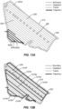
- FIG. 1 illustrates an exemplary work area 100.
- the work area 100 has a boundary or geofence 110.
- a second boundary 120 is inwardly offset from the geofence 110.
- the region inside the second boundary 120 may be the cropped area 130 with many swaths 132.
- the region between the geofence 110 and the second boundary 120 may be referred to herein as the headland 140.
- the geofence 110 may be referred to as the outer boundary of the headland 140.
- the second boundary 120 may be referred to as the inner boundary of the headland 140 or as the headland boundary.
- the offset distance between the geofence 110 and the second boundary 120 may be referred to as the width of the headland 140.
- a headland 140 may have a width that is an integer multiple of the implement width X being used. For instance, in the example illustrated in FIG. 1 , the width of the headland is equal to the implement width X.
- headland guideline may refer to a guidance line 150 inside the headland 140 that may be used as a route for a vehicle to traverse along to cover the headland 140 or transition from one track to a next track (or from one segment of a track to a next segment of the track).
- the guidance line 150 may be offset from the headland boundary 120 by a distance that is equal to one half of the implement width X.
- an area coverage planner can accommodate work areas (e.g., fields) with arbitrary boundary shapes.
- a work area can have a boundary with an irregular shape.
- the boundary can also include convex sections as well as concave sections.
- the work area can include static obstacles within the boundary.
- examples as applied to agricultural vehicles (e.g., tractors) working in fields will be used for illustration purposes. But embodiments of the present invention can be applied to applications other than agricultural applications, such as constructions.
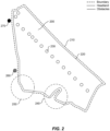
- FIG. 2 shows an exemplary field 200 with a boundary 210.
- the field 200 can have an optional headland guideline 220.
- the boundary 210 can have an irregular shape, and can have convex sections (e.g., the section 250) as well as concave sections (e.g., section 240).
- the field 200 can include some static obstacles 230 (e.g., electrical poles) within its boundary 210.
- an entry point 260 and an exit point 270 can be pre-defined.
- Information of the boundary 210 e.g., geometrical and location information
- information of the obstacles 230 e.g., geometrical and location information
- a first task for the area coverage planner may be to lay down the tracks for a vehicle to traverse in order to cover the entire field 200.
- FIG. 3A shows an exemplary layout of tracks (e.g., swaths) in the field 200 according to some embodiments.
- the tracks 310 can be a series of straight lines that cover the entire field 200.
- the tracks 310 can be advantageously made parallel to each other.
- the spacing between adjacent tracks 310 can be related to the width of an implement attached to the vehicle (e.g., equal to, slightly smaller, or slightly greater than the width of the implement, depending on whether an overlap or a gap in the coverage between adjacent tracks is desired). In this manner, as the vehicle traverses along a given track 310, the implement extends about one half of the track spacing on either side. Thus, as the vehicle completes traversing all the tracks 310 in the field, the entire field 200 can be covered.
- the spacing between adjacent tracks 310 can be specified by a user.
- some tracks 310 can intersect some of the obstacles 230.
- the track 312 intersects the obstacles 230a and 230b.
- the track 312 can be divided into three segments 312a, 312b, and 312c, as illustrated in FIG. 3B.
- FIG. 3B shows the tracks 310 without showing the obstacles 230, so as to show the segments more clearly.
- some tracks 310 can intersect the boundary 210.
- the track 314 intersects the concave section 240 of the boundary 210.
- the track 314 can be divided into two segments 314a and 314b, as illustrated in FIG. 3B .
- the vehicle may need to make a turn. For example, referring to FIG. 3B , to transition from the segment 312a to the segment 312b, the vehicle may need to make a semi-circular turn 320 to get around the obstacle 230a (the obstacle 230a is not shown in FIG. 3B ). Similarly, to transition from the segment 314a to the segment 314b, the vehicle may need to navigate along the curved path 330 (e.g., along the headland guideline 220) so as not to cross the concave section 240 of the boundary 210.
- the vehicle may need to navigate along the curved path 330 (e.g., along the headland guideline 220) so as not to cross the concave section 240 of the boundary 210.
- the vehicle may need to make an end-of-row-turn (e.g., a U-shaped turn along the headland guideline 220). Since the vehicle may need to slow down in order to make a turn, more number of turns can result in a longer total duration of time to traverse all the tracks. Therefore, it can be advantageous to lay down the tracks 310 in a way that minimizes the total number of segments to the extent possible.
- a track that does not intercept any obstacle 230 can be considered as one segment. The number of segments can depend on the offset and the direction of the tracks, as discussed below.
- FIGS. 4A and 4B illustrate two examples of offset for laying down tracks in the field 200.
- the term "offset" refers to the distance 420 of a first track 410 from the boundary 210.
- the value of the offset can be a parameter to be optimized by the area coverage planner. In the example shown in FIG. 4A , the value of the offset 420 is 23 meters. In the example shown in FIG. 4B , the value of the offset 420 is 100 meters.
- FIGS. 5A and 5B illustrate how the value of the offset 420 can affect the total number of segments in a track layout.
- the value of the offset is set to zero (i.e., the first track 410 starts at the boundary 210). Once the first track 410 is laid, the other tracks can be laid spaced apart from the first track 410 with an equal spacing with respect to each other (e.g., equal to the width of an implement attached to the vehicle).
- the track 510 intercepts the row of obstacles 230, and is divided into as many as fifteen segments 512.
- the value of the offset is set to 23 meters. As illustrated, here the tracks lie on either side of the row of obstacles 230. As a result, the track 520 intercepts only two obstacles 230, and is divided into as few as three segments 522.
- the track layout shown in FIG. 5B can be more advantageous than the track layout shown in FIG. 5A as it includes less number of segments.
- the vehicle would make a total of 202 turns (including turns for transitioning from one track to a next track, referred to as end-of-row-turns), travel a total distance of about 18042 meters, over a total duration of time of about 6227 seconds, in order to complete all the tracks to cover the entire field 200.
- end-of-row-turns travel a total distance of about 18042 meters, over a total duration of time of about 6227 seconds, in order to complete all the tracks to cover the entire field 200.
- the vehicle would make only a total of 154 turns (which is 48 turns less than 202 turns), travel a total distance of only 17330 meters (which is 712 meters less than 18042 meters), over a total duration of time of about 5907 seconds (which is 320 seconds less than 6227 seconds).
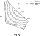
- FIGS. 6A and 6B illustrate two examples of the direction of tracks in the field 200.
- the tracks 610 are perpendicular to the horizontal axis (e.g., aligned with the North-South direction).
- the tracks 620 are tilted at 136 degrees with respect to the horizontal axis.
- FIGS. 7A and 7B illustrate how the direction of tracks can affect the total number of segments in a track layout.
- the tracks 610 are perpendicular to the horizontal axis
- many tracks 610 intercept the obstacles 230, and thus are divided into multiple segments.
- the tracks 620 are tilted at 136 degrees so that the tracks 620 lie on either side of the row of the obstacles 230
- only a few tracks e.g., the tracks 622 and 624
- the track layout shown in FIG. 7A includes a total of 26 tracks
- the track layout shown in FIG. 7B includes only a total of 18 tracks.
- the track layout shown in FIG. 7B can be more advantageous than the track layout shown in FIG. 7A as it includes less number of segments.
- the track layout shown in FIG. 7A would require a total of 208 turns, a total distance of about 18511 meters, and a total duration of time of about 6399 seconds.
- the track layout shown in FIG. 7B would require only 154 turns (which is 54 turns less than 202 turns), a total distance of only about 17330 meters (which is 1181 meters less than 18042 meters), and a total duration of time of only about 5907 seconds (which is 492 seconds less than 6227 seconds).
- a track layout can include curved tracks.
- FIG. 7C illustrate an example.
- the tracks 630 have a slight curvature (e.g., arc-shaped), and are spaced apart from each other by a spacing. Tracks with other gradual curved shapes are also possible.
- a slight curvature e.g., arc-shaped
- an area coverage planner can optimize both the offset and the direction of the tracks in a track layout.
- the area coverage planner can perform a multivariate optimization to obtain an optimal offset and an optimal direction of the tracks based on a heuristic objective.
- the heuristic objective can include one of more of the following: minimum total distance traveled, minimum total duration, minimum number of turns, and maximum coverage. These objectives can be interrelated. For example, minimum total distance and minimum number of turns can help achieve minimum total duration.
- the offset and the direction of the tracks are optimized simultaneously.
- the next task for the area coverage planner is to generate a trajectory for an autonomous vehicle to traverse the tracks to cover the work area.
- FIG. 8 shows an exemplary trajectory 810 for traversing the tracks 620 shown in FIG. 7B (the tracks are overlaid with the trajectory 810).
- An entry point 260 and an exit point 270 can be optionally pre-defined.
- the trajectory 810 can start from the entry point 260, and then continue along a section 220a of the headland guideline 210 onto the first track 620a.
- the trajectory 810 then traverses the tracks sequentially until it completes the last track 620b, and then continues along a section 220b of the headland guideline 210 to reach the exit point 270.
- the trajectory 810 can include a turn along a section of the headland guideline 220 (e.g., the section 220c).
- the trajectory 810 can include a turn along a section of the headland guideline 220 (e.g., the section 220d).
- the trajectory 810 can include a turn around the obstacle 230 (e.g., the turn 820).
- FIGS. 9A and 9B illustrate a concept of route planning according to some embodiments.
- a field 900 with a boundary 910 includes a network of roads (e.g., the roads 930, 932, and 934).
- Each road can have an associated unit cost of traversing that road (e.g., cost per meter).
- each road can be specified to be a bidirectional (e.g., two-way road) or unidirectional (e.g., one-way road).
- the end points of each road e.g., the end point 930a of the road 930
- the cross-road points where two road cross each other e.g., the cross road point 940 where the road 932 and the road 930 cross each other
- traveling off-road e.g., in areas where no road exits
- the task of a route planner may be to find an optimal route from a starting point 960 to a goal point 970 that will incur a minimum cost.
- FIG. 9B shows a possible optimal route 990 that the route planner can generate.
- the optimal route 990 e.g., represented by the thick dashed line
- the optimal route 990 can include a relatively short off-road segment 990a between the starting point 960 and a nearest road 930, and a relatively short off-road segment 990b between the goal point 970 and a nearest road 932.
- the optimal route 990 can include an on-road section that has a shortest total distance traveled. For instance, in the example illustrated in FIG.
- the on-road section can include a first sub-section on the road 930, and a second sub-section on the road 932.
- the total distance of the first sub-section and the second sub-section can be the shortest possible distance.
- transitioning from the road 930 to the road 932 occurs at the node 940 at which the road 930 and the road 932 cross each other.
- FIG. 10 shows how the route-planning concept discussed above can be applied to optimizing an entry route and an exit route according to some embodiments.
- the tracks 620 and the headland guideline 220 form the network of roads.
- the starting point can be the entry point 260, and the goal point 1014.
- the goal point 1014 can be the beginning of the first track 620a.
- An optimal entry route 1010 can include a relatively short off-road segment 1012 between the entry point 260 and a nearest point 1016 on the headland guideline 220, followed by a segment along the headland guideline 220 to the goal point 1014.
- the starting point 1024 can be the end of the last track 620b, and the goal point can be the exit point 270.
- An optimal exit route 1020 can include a segment along the headland guideline 220, followed by a relatively short off-road segment between the exit point 270 and a nearest point 1026 on the headland guideline 220.
- the area coverage planner can convert the route into a traversable trajectory to be used for guiding an autonomous vehicle.
- a traversable trajectory is one that can be executed by the autonomous vehicle given its motion limitations. For example, the autonomous vehicle may not be able to make a sharp turn due to its motion constraints. In a traversable trajectory, sharp corners can be converted into traversable corners.
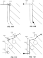
- FIGS. 11A - 11D illustrate the conversion from routes into traversable trajectories according to some embodiments.
- FIG. 11A shows the entry route 1010 (solid line) as shown in FIG. 10 .
- the entry route 1010 includes a sharp corner 1112.
- FIG. 11B shows a traversable trajectory 1120 (dashed line) converted from the entry route 1010.
- the sharp corner 1112 in the entry route is converted into a rounded corner 1122 in the traversable trajectory 1120, so that the autonomous vehicle may be able to execute the turn.
- FIG. 11C shows the exit route 1020 (solid line) as shown in FIG. 10 .
- the exit route 1020 includes three sharp turns 1132, 1134, and 1136.
- FIG. 11D shows a traversable trajectory 1140 (dashed line) converted from the exit route 1020.
- the sharp corners 1132, 1134, and 1136 are converted into rounded corners 1142, 1144, and 1146, respectively, so that the autonomous vehicle may be able to execute the turns.
- the area coverage planner can also generate a velocity profile for the traversable trajectory.
- the velocity profile can specify a speed for the autonomous vehicle at each respective point along the traversable trajectory.
- the velocity profile can specify a work speed for the segments along the tracks, and specify a turn speed along turns.
- the turn speed is usually slower than the work speed.
- the velocity profile can specify transition speeds for the transitions from the work speed to the turn speed, or vice versa. The transition speeds can be determined based on the nominal acceleration of the autonomous vehicle.
- FIGS. 12A - 12C illustrate an exemplary velocity profile for the trajectory 810 shown in FIG. 8 .
- the velocity profile is represented by dots of various sizes, the larger the dots, the slower the speed. As illustrated, the speed is substantially uniform along the segments of the tracks 620 (the uniform dots may appear as continuous lines), and is slower along the turns.
- FIG. 12B shows a close-up view of the velocity profile for the area 1210 shown in FIG. 12A.
- FIG. 12C shows a close-up view of the velocity profile for the area 1220 shown in FIG. 12A .
- the dots are shown in equal time interval along the trajectory. Thus, the dots would appear to be uniformly spaced from each other if the speed is constant, and would appear to be closer to each other if the speed is decreased.
- FIG. 12B includes the velocity profile along two adjacent tracks 620p and 620q.
- the track 620p does not intercept the obstacle 230a, whereas the track 620q intercepts the obstacle 230a.
- the speed along the track 620p is nearly constant (e.g., at work speed), as indicated by the uniform spacing between adjacent dots.
- the trajectory along the track 620q includes a turn in order to get around the obstacle 230a.
- the speed along the track 620q slows down during the turns, as indicated by the reduced spacing between adjacent dots.
- FIG. 12C includes the velocity profile for the end-of-row turn from one track 620r to a next track 620s.
- the trajectory for the turn has a "U" shape, including a section along the headland guideline 220.
- Other types of end-of-row-turns are also possible, e.g., as described in U.S. Patent Application Nos. 16/863,056 and 16/863,049 , the contents of which are incorporated by reference.
- the speed is reduced around the corners of the trajectory when transitioning from the track 620r to the headland guideline 220, and from the headland guideline 220 to the next track 620s.
- the tracks can be traversed according to various strategies.
- FIGS. 13A and 13B illustrate two exemplary strategies.
- the thick black line indicates the trajectory.
- the tracks 620 are traversed sequentially. For example, after completing the first track 620a, the next adjacent track 620b is traversed, followed by the next adjacent track 620c, and so on and so forth, until the last track 620d is completed.
- the tracks 620 are traversed in a "race track" pattern.
- the next track to be traversed is the sixth track 1310b, skipping four tracks in between.
- the trajectory can follow the headland guideline 220 when transitioning from the first track 1310a to the sixth track 1310b.
- the next track to be traversed is the 11th track 13 10c, again skipping four tracks in between.
- the next track to be traversed is the 16th track 1310d, again skipping four tracks in between.
- the next track to be traversed is the last track 1310e (the 18th track). It then repeats the pattern of skipping four tracks by traversing the tracks 1310f, 1310g, and 1310h, in this order.
- the "race track" strategy can have the advantage that the turns from one track to a next track are wider.
- the trajectory can traverse the tracks in other non-sequential patterns.
- the headland 220 in the periphery of the field 200 may not be covered.
- the area coverage planner can include a headland pass in the trajectory.
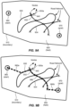
- FIGS. 14A and 14B illustrate two examples. In the example shown in FIG.
- the trajectory 1410 (represented by the thick black line) can start from the entry point 260 onto the headland guideline 220, and then traverse the entire headland guideline 220 before starting to traverse the tracks 620.
- the trajectory 1420 (represented by the thick black line) traverse the tracks 620 first (the tracks are overlaid with the trajectory 1320, and therefore are not visible), and then traverse the entire headland guideline 220 before going to the exit point 270.
- a user can be presented with three options: (i) headland pass on entry, (ii) headland pass on exit, and (iii) no headland pass.
- the three options can be presented to the user on a graphics user interface (GUI). The user can select one of them.
- GUI graphics user interface
- FIG. 15A shows a simplified flowchart illustrating a method 1510 of area coverage planning for an autonomous vehicle according to some embodiments.
- the method 1510 includes, at 1512, receiving information of a boundary of a work area; and at 1514, receiving information of one or more obstacles located within the work area.
- the method 1510 further includes, at 1516, laying a plurality of tracks within the boundary of the work area.
- the plurality of tracks are spaced apart from each other by a spacing.
- Laying the plurality of tracks comprises: based on (i) the information of the boundary of the work area, and (ii) the information of the one or more obstacles, performing a multivariate optimization to: (i) determine an optimal direction of the plurality of tracks, and (ii) an optimal offset for a first track from the boundary, so as to minimize a total distance of the plurality of tracks.
- the method 1510 further includes, at 1518 generating a trajectory that is traversable by the autonomous vehicle to traverse the plurality of tracks.
- FIG. 15A provides a particular method of area coverage planning for an autonomous vehicle according to some embodiments. Other sequences of steps may also be performed according to alternative embodiments. For example, alternative embodiments of the present invention may perform the steps outlined above in a different order. Moreover, the individual steps illustrated in FIG. 15A may include multiple sub-steps that may be performed in various sequences as appropriate to the individual step. Furthermore, additional steps may be added or removed depending on the particular applications.
- One of ordinary skill in the art would recognize many variations, modifications, and alternatives.
- FIG. 15B shows a simplified flowchart illustrating a method 1520 of area coverage planning for an autonomous vehicle according to some embodiments.
- the method 1520 includes, at 1522, receiving information of a boundary of a work area; and at 1524, laying a plurality of tracks within the boundary of the work area.
- the plurality of tracks are spaced apart from each other by a spacing.
- Laying the plurality of tracks comprises: based on the information of the boundary of the work area, performing a multivariate optimization to: (i) determine an optimal direction of the plurality of tracks, and (ii) an optimal offset for a first track from the boundary, so as to minimize a total distance of the plurality of tracks.
- the method 1520 further includes, at 1526 generating a trajectory that is traversable by the autonomous vehicle to traverse the plurality of tracks.
- FIG. 15B provides a particular method of area coverage planning for an autonomous vehicle according to some embodiments. Other sequences of steps may also be performed according to alternative embodiments. For example, alternative embodiments of the present invention may perform the steps outlined above in a different order. Moreover, the individual steps illustrated in FIG. 15B may include multiple sub-steps that may be performed in various sequences as appropriate to the individual step. Furthermore, additional steps may be added or removed depending on the particular applications.
- One of ordinary skill in the art would recognize many variations, modifications, and alternatives.
- an area coverage planner can include replenishment planning during coverage. After a coverage trajectory (e.g., a single traversable trajectory covering the entire work area) has been generated, logistic points along the coverage trajectory at which the autonomous vehicle needs to be replenished can be computed according to a strategy. Provided with the locations of one or more refill stations adjacent to the boundary of the work area, the replenishment planner can generate a replenishment trajectory for each logistic point.
- the replenishment trajectory includes a first part from the logistic point to a refill station, and a second part from the refill station to a resume point.
- FIG. 16 shows a field 200 with several refill stations.
- a first refill station 1610 can be located adjacent the entry point 260
- the second refill station 1620 can be located adjacent the exit point 270
- a third refill station 1630 can be located adjacent the boundary 210 on the other side of the field 200.
- the solid line indicates a trajectory 1690 for an autonomous vehicle to traverse the tracks to cover the field 200, which can be referred herein as a coverage trajectory. While traversing the coverage trajectory 1690, the autonomous vehicle can run out of the material at certain points (e.g., at the point 1640). Thus, the autonomous vehicle may need to go to one of the refill stations 1610, 1620, or 1630 to be replenished with the material, before resuming the coverage trajectory.
- the area coverage planner can first generate the coverage trajectory (e.g., a single traversable trajectory covering the entire field 200 while avoiding obstacles), using the methods discussed above.
- the area coverage planner can compute logistic points along the coverage trajectory where the autonomous vehicle would need to be replenished with the material.
- the area coverage planner can then generate a traversable trajectory from each respective logistic point to a respective refill station, and then from the respective refill station to a corresponding resume point.
- the trajectory from a logistic point to a refill station, and from the refill station to a resume point can be referred to as a replenishment trajectory.
- the logistic points can be computed according to various strategies according to some embodiments.
- One strategy is to compute the logistic points based on threshold.
- a logistic point can be a point at which the remaining load of the material falls below a predetermined threshold. This strategy can be referred to as trigger at threshold.
- the threshold can be a percentage of a nominal full load (e.g., 20% of the nominal full load), or can be an absolute amount of the material (e.g., 100 liters, assuming a nominal full load of 500 liters).
- a logistic point can be computed based on the distance the autonomous vehicle has traveled since the last refill based on the nominal consumption rate.
- the autonomous vehicle stops consuming the material e.g., stop spraying fertilizer or seeds
- the distance traveled during end-of-row-turns can be excluded in the calculation.
- FIG. 17 illustrates the strategy of trigger at threshold according to some embodiments.
- a refill station 1730 is located adjacent to the boundary 1710. Assume that the coverage trajectory 1760 (thin solid line) traverses the tracks sequentially, starting from the entry point 1702. It can be computed that a first logistic point will be reached at the location 1740. When the first logistic point 1740 is reached, the autonomous vehicle will need to go to the refill station 1730 to be replenished with the material. For example, the autonomous vehicle can continue to the end of the track 1742, and then follow the headland guideline 1720 to the refill station 1730 (along the thick grey line).
- the autonomous vehicle can follow the headland guideline 1720 to the track 1742, and then along the track 1742 back to the first logistic point 1740 (along the thick black line).
- the autonomous vehicle can then resume work by traversing along the coverage trajectory 1760 from the first logistic point 1740.
- the logistic point is also the resume point.
- the trajectory from the first logistic point 1740 to the refill station 1730 (along the thick grey line), and from the refill station 1730 back to the first logistic point 1740 (along the thick black line) is referred to as a replenishment trajectory.
- Additional logistic points can be computed in a similar manner, and the associated replenishment trajectories from each logistic point to the refill station 1730 (along the thick grey line) and from the refill station 1730 to the corresponding resume point (along the thick black line) can be determined.
- the autonomous vehicle While the autonomous vehicle is traversing the replenishment trajectory (e.g., along the thick grey line and the thick black line), the autonomous vehicle can stop consuming the material (e.g., stop spraying fertilizer or seeds).
- Another strategy is to compute logistic points at end-of-row according to some embodiments.
- a logistic point is always at the end of a track.
- the replenishment planner can compute a logistic point to be at the end of a track, beyond which the autonomous vehicle may not have enough material to last through the next track.
- FIGS. 18A - 18D illustrate some examples.
- a first logistic point 1840 can be computed to be at the end of the track 1844. After the autonomous vehicle has completed the track 1844, it would not have enough material to last through the next track 1846. Thus, the autonomous vehicle would need to go to one of the refill stations 1820 and 1830 to be replenished with the material.
- the replenishment planner can generate a replenishment trajectory from the logistic point 1840 to a first refill station 1820 (along the thick grey line), and after the refill, from the first refill station 1820 to the beginning of the next track 1846 (along the thick black line). The beginning of the next track 1846 is the resume point 1842.
- a second logistic point 1850 can be computed to be at the end of the track 1854.
- the replenishment planner can generate a replenishment trajectory from the second logistic point 1850 to the second refill station 1830 (along the thick grey line), and after the refill, from the second refill station 1830 to the resume point 1852 at beginning of the next track 1856 (along the thick black line).
- a third logistic point 1860 can be computed to be at the end of the track 1864.
- the replenishment planner can generate a replenishment trajectory from the third logistic point 1860 to the second refill station 1830 (along the thick grey line), and after the refill, from the second refill station 1830 to the resume point 1862 at the beginning of the next track 1866 (along the thick black line).
- FIG. 18D shows all three replenishment trajectories.
- the logistic point is always at the end of a track, and the resume point is always at the beginning of a next track.
- the autonomous vehicle is traversing a replenishment trajectory (e.g., along the thick grey line and the thick black line), the vehicle can stop consuming the material (e.g., stop spraying fertilizer or seeds).
- FIG. 19 shows a simplified flowchart illustrating a method 1900 of area coverage planning with replenishment planning for an autonomous vehicle according to some embodiments.
- the method 1900 includes, at 1902, receiving information of a boundary of the work area; at 1904, receiving location information of one or more refill stations for replenishing the material; and at 1906, receiving information of a current amount of the material left in the autonomous vehicle.
- the method 1900 further includes, at 1908, based on the information of the boundary of the work area, laying a plurality of tracks within the boundary of the work area so as to minimize a total distance of the plurality of tracks.
- the plurality of tracks are spaced apart from each other by a spacing.
- the method 1900 further includes, at 1910, generating a coverage trajectory that is traversable by the autonomous vehicle to traverse the plurality of tracks.
- the method 1900 further includes, at 1912, based on (i) the coverage trajectory, (ii) the location information of the one or more refill stations, (iii) the current amount of the material left in the autonomous vehicle, and (iv) a nominal full amount and a nominal consumption rate of the material by the autonomous vehicle, determining one or more logistic points along the coverage trajectory at which a remaining amount of the material reaches a threshold.
- the method 1900 further includes, at 1914, for each respective logistic point of the one or more logistic points, generating a respective replenishment trajectory for the autonomous vehicle.
- the respective replenishment trajectory includes: a first part from the respective logistic point to a respective refill station of the one of the one or more refill stations for replenishing the autonomous vehicle with the material, and a second part from the respective refill station to the respective logistic point for the autonomous vehicle to resume traversing the coverage trajectory.
- FIG. 19 provides a particular method of area coverage planning with replenishment planning for an autonomous vehicle according to some embodiments. Other sequences of steps may also be performed according to alternative embodiments. For example, alternative embodiments of the present invention may perform the steps outlined above in a different order. Moreover, the individual steps illustrated in FIG. 19 may include multiple sub-steps that may be performed in various sequences as appropriate to the individual step. Furthermore, additional steps may be added or removed depending on the particular applications. One of ordinary skill in the art would recognize many variations, modifications, and alternatives.
- FIG. 20 shows a simplified flowchart illustrating a method 2000 of area coverage planning with replenishment planning for an autonomous vehicle according to some embodiments.
- the method 2000 includes, at 2002, receiving information of a boundary of the work area; at 2004, receiving location information of one or more refill stations for replenishing the material; and at 2006, receiving information of a current amount of the material left in the autonomous vehicle.
- the method 2000 further includes, at 2008, based on the information of the boundary of the work area, laying a plurality of tracks within the boundary of the work area so as to minimize a total distance of the plurality of tracks.
- the plurality of tracks are spaced apart from each other by a spacing.
- the method 2000 further includes, at 2010, generating a coverage trajectory that is traversable by the autonomous vehicle to traverse the plurality of tracks.
- the method 2000 further includes, at 2012, based on (i) the coverage trajectory, (ii) the location information of the one or more refill stations, (iii) the current amount of the material left in the autonomous vehicle, and (iv) a nominal full amount and a nominal consumption rate of the material by the autonomous vehicle, determining one or more logistic points along the coverage trajectory at which the autonomous vehicle needs to be replenished with the material. Each respective logistic point is at an end of a respective track.
- the method 2000 further includes, at 2014, for each respective logistic point of the one or more logistic points, generating a respective replenishment trajectory for the autonomous vehicle.
- the respective replenishment trajectory includes: a first part from the respective logistic point to a respective refill station of the one of the one or more refill stations for replenishing the autonomous vehicle with the material, and a second part from the respective refill station to a beginning of a next track for the autonomous vehicle to resume traversing the coverage trajectory.
- FIG. 20 provides a particular method of area coverage planning with replenishment planning for an autonomous vehicle according to some embodiments. Other sequences of steps may also be performed according to alternative embodiments. For example, alternative embodiments of the present invention may perform the steps outlined above in a different order. Moreover, the individual steps illustrated in FIG. 20 may include multiple sub-steps that may be performed in various sequences as appropriate to the individual step. Furthermore, additional steps may be added or removed depending on the particular applications. One of ordinary skill in the art would recognize many variations, modifications, and alternatives.
- FIG. 21 shows a simplified diagram of a system 2100 for an autonomous vehicle according to some embodiments.
- the system 2100 may include an area coverage planning module 2180, and a user interface 2150.
- the user interface 2150 may also include a display.
- the area coverage planning module 2180 can include one or more computer processors configured to perform area coverage planning according to the embodiments described above.
- the area coverage planning can include laying down the tracks and generating a traversable coverage trajectory for the autonomous vehicle.
- the area coverage planning module 2180 can also perform replenishment planning according to the embodiments described above.
- Replenishment planning can include computing logistic points according to various strategies, and generating replenishment trajectories.
- the coverage trajectory and the replenishment trajectories can be displayed in a display (e.g., the display in the user interface 2150).
- the system 2100 can include a memory 2190.
- the memory 2190 can store information needed for the area coverage planning module 2180, as well as other information.
- the memory 2190 can store information about a work area, such as a boundary (e.g., a geofence) and headland guidelines.
- the memory 2190 can also store information of any static obstacles located within the boundary, the location of an entry point, and the location of an exit point.
- the memory 2190 can also store information of the locations of one or more refill stations.
- the memory 2190 can also store information about the nominal full load of a material that the autonomous vehicle may spray along the coverage trajectory, and the nominal consumption rate of the material, as well as a threshold load for triggering a logistic point.
- the memory 2190 can also store computer-executable instructions to be executed by the computer processors of the area coverage planning module 2180.
- the memory 2190 may comprise a volatile memory random access memory (RAM), or nonvolatile data storage device such as a hard disk drive, flash memory or other optical or magnetic storage device.
- the area coverage planning module 2180 may include its own memory.
- the system 2100 may include a global navigation satellite systems (GNSS) antenna 2120 attached to the autonomous vehicle, and a GNSS receiver 2110 coupled to the GNSS antenna 2120.
- the GNSS receiver 2110 may be configured to determine a current position of the vehicle based on the satellite signals received from GNSS satellites.
- the system 2100 can also include an optional position correction system 2130.
- the position correction system 2130 may include an antenna 2132 and a receiver 2134 for receiving correction data from a reference station or a network of reference stations.
- the position correction system 2130 may include a differential global positioning system (DGPS).
- DGPS differential global positioning system
- the correction data may be used by the GNSS receiver 2110 to determine a more precise position of the vehicle (e.g., to millimeter or sub-millimeter accuracies).
- the GNSS receiver 2110 may be an independent unit separate from the system 2100.
- the system 2100 can include other sensors 2140.
- the other sensors 2140 may include LiDAR sensors for obstacle detection, inertial measurement units or IMUs (e.g., accelerometers and gyroscopes), wheel angle sensors, and the like.
- IMUs inertial measurement units
- wheel angle sensors and the like.
- the various components of the system 2100 may be interconnected with each other via a bus 2102. In some other embodiments, the various components may be connected with each other in other ways.
Landscapes
- Engineering & Computer Science (AREA)
- Radar, Positioning & Navigation (AREA)
- Remote Sensing (AREA)
- Physics & Mathematics (AREA)
- General Physics & Mathematics (AREA)
- Automation & Control Theory (AREA)
- Business, Economics & Management (AREA)
- Aviation & Aerospace Engineering (AREA)
- Human Resources & Organizations (AREA)
- Strategic Management (AREA)
- Economics (AREA)
- Theoretical Computer Science (AREA)
- Tourism & Hospitality (AREA)
- General Business, Economics & Management (AREA)
- Entrepreneurship & Innovation (AREA)
- Marketing (AREA)
- Life Sciences & Earth Sciences (AREA)
- Animal Husbandry (AREA)
- Operations Research (AREA)
- Educational Administration (AREA)
- Game Theory and Decision Science (AREA)
- Development Economics (AREA)
- Agronomy & Crop Science (AREA)
- Quality & Reliability (AREA)
- Marine Sciences & Fisheries (AREA)
- Mining & Mineral Resources (AREA)
- Health & Medical Sciences (AREA)
- General Health & Medical Sciences (AREA)
- Primary Health Care (AREA)
- Control Of Position, Course, Altitude, Or Attitude Of Moving Bodies (AREA)
Claims (10)
- Verfahren zur Flächenabdeckungsplanung mit Auffüllplanung für ein autonomes Fahrzeug, welches Material auf einer Arbeitsfläche (200) verteilt, wobei das Verfahren an einem Computersystem umfasst:Empfangen von Informationen über eine Grenze (210) der Arbeitsfläche (200);Empfangen von Positionsinformationen für eine oder mehrere Nachfüllstationen (1610, 1620, 1630, 1730, 1820, 1830) zum Auffüllen des Materials;Empfangen von Informationen über eine aktuelle Menge des Materials, die in dem autonomen Fahrzeug noch übrig ist;Auslegen mehrerer Bahnen (310) innerhalb der Grenze (210) der Arbeitsfläche (200) auf Grundlage der Informationen über die Grenze (210) der Arbeitsfläche (200), derart, dass eine Gesamtstrecke der mehreren Bahnen (310) minimiert wird, wobei die mehreren Bahnen (310) einen Abstand voneinander aufweisen;Erzeugen einer Abdeckungstrajektorie (1690, 1760), welche von dem autonomen Fahrzeug durchfahrbar ist, um die mehreren Bahnen (310) zu durchfahren;Bestimmen eines oder mehrerer Logistikpunkte (1740, 1750, 1760, 1840, 1850, 1860) entlang der Abdeckungstrajektorie (1690, 1760), an welchen eine verbleibende Menge des Materials einen Schwellenwert erreicht, auf Grundlage (i) der Abdeckungstrajektorie (1690, 1760), (ii) der Positionsinformationen für die eine oder die mehreren Nachfüllstationen (1610, 1620, 1630, 1730, 1820, 1830), (iii) der aktuellen Menge des Materials, die in dem autonomen Fahrzeug noch übrig ist, und (iv) einer Nenn-Füllmenge und einer Nenn-Verbrauchsgeschwindigkeit des Materials durch das autonome Fahrzeug; undErzeugen einer jeweiligen Auffülltrajektorie für das autonome Fahrzeug für jeden entsprechenden Logistikpunkt des einen oder der mehreren Logistikpunkte (1740, 1750, 1760, 1840, 1850, 1860), wobei die jeweilige Auffülltrajektorie umfasst:einen ersten Teil von dem jeweiligen Logistikpunkt bis zu einer jeweiligen Nachfüllstation der einen der einen oder der mehreren Nachfüllstationen (1610, 1620, 1630, 1730, 1820, 1830) zum Auffüllen des autonomen Fahrzeugs mit dem Material; undeinen zweiten Teil von der jeweiligen Nachfüllstation bis zu dem jeweiligen Logistikpunkt für das autonome Fahrzeug zum Wiederaufnehmen des Durchfahrens der Abdeckungstrajektorie (1690, 1760);dadurch gekennzeichnet, dass das Auslegen der mehreren Bahnen (310) umfasst:
Durchführen einer multivariaten Optimierung zum: (i) Bestimmen einer optimalen Richtung der mehreren Bahnen (310) und (ii) eines optimalen Abstands für eine erste Bahn (410) von der Grenze (210), um die Gesamtstrecke der mehreren Bahnen (310) zu minimieren. - Verfahren zur Flächenabdeckungsplanung mit Auffüllplanung für ein autonomes Fahrzeug, welches Material auf einer Arbeitsfläche (200) verteilt, wobei das Verfahren an einem Computersystem umfasst:Empfangen von Informationen über eine Grenze (210) der Arbeitsfläche (200);Empfangen von Positionsinformationen für eine oder mehrere Nachfüllstationen (1610, 1620, 1630, 1730, 1820, 1830) zum Auffüllen des Materials;Empfangen von Informationen über eine aktuelle Menge des Materials, die in dem autonomen Fahrzeug noch übrig ist;Auslegen mehrerer Bahnen (310) innerhalb der Grenze (210) der Arbeitsfläche (200) auf Grundlage der Informationen über die Grenze (210) der Arbeitsfläche (200), derart, dass eine Gesamtstrecke der mehreren Bahnen (310) minimiert wird, wobei die mehreren Bahnen (310) einen Abstand voneinander aufweisen;Erzeugen einer Abdeckungstrajektorie (1690, 1760), welche von dem autonomen Fahrzeug durchfahrbar ist, um die mehreren Bahnen (310) zu durchfahren;Bestimmen eines oder mehrerer Logistikpunkte (1740, 1750, 1760, 1840, 1850, 1860) entlang der Abdeckungstrajektorie (1690, 1760), an welchen das autonome Fahrzeug mit dem Material aufgefüllt werden muss, auf Grundlage (i) der Abdeckungstrajektorie (1690, 1760), (ii) der Positionsinformationen für die eine oder die mehreren Nachfüllstationen (1610, 1620, 1630, 1730, 1820, 1830), (iii) der aktuellen Menge des Materials, die in dem autonomen Fahrzeug noch übrig ist, und (iv) einer Nenn-Füllmenge und einer Nenn-Verbrauchsgeschwindigkeit des Materials durch das autonome Fahrzeug, wobei sich der jeweilige Logistikpunkt an einem Ende einer jeweiligen Bahn (310) befindet; undErzeugen einer jeweiligen Auffülltrajektorie für das autonome Fahrzeug für jeden entsprechenden Logistikpunkt des einen oder der mehreren Logistikpunkte (1740, 1750, 1760, 1840, 1850, 1860), wobei die jeweilige Auffülltrajektorie umfasst:einen ersten Teil von dem jeweiligen Logistikpunkt bis zu einer jeweiligen Nachfüllstation der einen der einen oder der mehreren Nachfüllstationen (1610, 1620, 1630, 1730, 1820, 1830) zum Auffüllen des autonomen Fahrzeugs mit dem Material; undeinen zweiten Teil von der jeweiligen Nachfüllstation bis zu einem Beginn einer nächsten Bahn (310) für das autonome Fahrzeug zum Wiederaufnehmen des Durchfahrens der Abdeckungstrajektorie;dadurch gekennzeichnet, dass das Auslegen der mehreren Bahnen (310) umfasst:
Durchführen einer multivariaten Optimierung zum: (i) Bestimmen einer optimalen Richtung der mehreren Bahnen (310) und (ii) eines optimalen Abstands für eine erste Bahn (410) von der Grenze (210), um die Gesamtstrecke der mehreren Bahnen (310) zu minimieren. - Verfahren nach Anspruch 1 oder 2, wobei die Grenze (210) eine unregelmäßige Form aufweist und mindestens eine Bahn der mehreren Bahnen (310) die Grenze (210) überschneidet, wodurch sie in zwei oder mehrere Segmente unterteil wird.
- Verfahren nach Anspruch 3, wobei die multivariate Optimierung durchgeführt wird, um eine Gesamtzahl an Segmenten in den mehreren Bahnen (310) weiter zu minimieren.
- Verfahren nach Anspruch 1 oder 2, ferner umfassend Empfangen von Informationen über ein oder mehrere Hindernisse (230), die sich innerhalb der Arbeitsfläche (200) befinden, an dem Computersystem, wobei:wenn eine jeweilige Bahn der mehreren Bahnen (310) die Grenze (210) oder mindestens ein Hindernis (230) des einen oder der mehreren Hindernisse (230) überschneidet, die entsprechende Bahn in zwei oder mehr Segmente (312a, 312b, 312c, 512, 522) unterteilt wird; unddie multivariate Optimierung ferner auf Grundlage der Informationen über das eine oder die mehreren Hindernisse (230) durchgeführt wird, um eine Gesamtzahl an Segmente in den mehreren Bahnen (310) zu minimieren.
- Verfahren nach Anspruch 1 oder 2, ferner umfassend Erzeugen eines Geschwindigkeitsprofils für das autonome Fahrzeug entlang der Abdeckungstrajektorie (1690, 1760).
- Verfahren nach Anspruch 1 oder 2, ferner umfassend an dem Computersystem:Empfangen einer Position eines Eintrittspunktes (260) und einer Position eines Austrittspunktes (270);wobei die Abdeckungstrajektorie (1690, 1760) eine Eintrittsroute (1010) von der Position des Eintrittspunktes (260) bis zu einer ersten Bahn und eine Austrittsroute (1020) von einer letzten Bahn bis zu dem Austrittspunkt (270) umfasst.
- Verfahren nach Anspruch 1 oder 2, wobei die Abdeckungstrajektorie (1690, 1760) ferner eine Landzungenpassage entlang einer Landzungen-Führungslinie (220) umfasst.
- Verfahren nach Anspruch 1 oder 2, wobei die Abdeckungstrajektorie (1690, 1760) die mehreren Bahnen (310) nacheinander oder nicht nacheinander durchfährt.
- Verfahren nach Anspruch 1 oder 2, wobei sich der Abstand zwischen benachbarten Bahnen der mehreren Bahnen (310) auf eine Breite eines Werkzeugs bezieht, das an dem autonomen Fahrzeug angebracht ist.
Applications Claiming Priority (1)
| Application Number | Priority Date | Filing Date | Title |
|---|---|---|---|
| US17/328,260 US11874665B2 (en) | 2021-05-24 | 2021-05-24 | Area coverage planner with replenishment planner |
Publications (2)
| Publication Number | Publication Date |
|---|---|
| EP4095644A1 EP4095644A1 (de) | 2022-11-30 |
| EP4095644B1 true EP4095644B1 (de) | 2024-08-07 |
Family
ID=81748930
Family Applications (1)
| Application Number | Title | Priority Date | Filing Date |
|---|---|---|---|
| EP22174233.1A Active EP4095644B1 (de) | 2021-05-24 | 2022-05-19 | Verfahren zur flächenabdeckung mit nachfüllplaner |
Country Status (2)
| Country | Link |
|---|---|
| US (1) | US11874665B2 (de) |
| EP (1) | EP4095644B1 (de) |
Families Citing this family (5)
| Publication number | Priority date | Publication date | Assignee | Title |
|---|---|---|---|---|
| JP7306191B2 (ja) * | 2019-09-26 | 2023-07-11 | コベルコ建機株式会社 | 輸送車位置判定装置 |
| US12065788B2 (en) * | 2021-06-23 | 2024-08-20 | Caterpillar Paving Products Inc. | System and method for marking a boundary while defining an autonomous worksite |
| JP7593901B2 (ja) * | 2021-09-01 | 2024-12-03 | ヤンマーホールディングス株式会社 | 自動走行方法、自動走行システム、及び自動走行プログラム |
| EP4544894A1 (de) * | 2023-10-23 | 2025-04-30 | Deere & Company | Verwendung von abdeckungsgebieten bei der steuerung von operationen einer landwirtschaftlichen maschine |
| CN121313898A (zh) * | 2025-12-08 | 2026-01-13 | 深圳聚瑞云控科技有限公司 | 一种药量补充工单生成方法、系统、设备及存储介质 |
Family Cites Families (24)
| Publication number | Priority date | Publication date | Assignee | Title |
|---|---|---|---|---|
| US6907336B2 (en) * | 2003-03-31 | 2005-06-14 | Deere & Company | Method and system for efficiently traversing an area with a work vehicle |
| US8204654B2 (en) | 2008-03-20 | 2012-06-19 | Deere & Company | System and method for generation of an inner boundary of a work area |
| US8983767B2 (en) | 2012-03-02 | 2015-03-17 | Jaybridge Robotics, Inc. | Computer-implemented method and system for generating swath coverage patterns for polygonal and pseudo-polygonal shaped fields |
| DE102014108536A1 (de) | 2014-06-17 | 2015-12-17 | Claas E-Systems Kgaa Mbh & Co Kg | Verfahren zur Bestimmung von Sollfahrspuren |
| EP2984916B1 (de) | 2014-08-11 | 2022-12-14 | CLAAS E-Systems GmbH | Verfahren zur Planung einer Route einer landwirtschaftlichen Maschine |
| WO2017026080A1 (ja) | 2015-08-13 | 2017-02-16 | ヤンマー株式会社 | 自律走行車の経路設計方法 |
| DE102015115510A1 (de) | 2015-09-15 | 2017-03-16 | Claas Selbstfahrende Erntemaschinen Gmbh | Fahrerassistenzsystem für eine landwirtschaftliche Arbeitsmaschine |
| US10266201B2 (en) | 2015-11-19 | 2019-04-23 | Agjunction Llc | K-turn path controller |
| US11044842B2 (en) * | 2015-12-03 | 2021-06-29 | Mogens Max Sophus Edzard Graf Piessen | Path planning for area coverage |
| CN109310042B (zh) | 2016-09-05 | 2022-07-19 | 株式会社久保田 | 作业车自动行驶系统、行驶路径管理装置、行驶路径生成装置、行驶路径决定装置 |
| JP6674877B2 (ja) | 2016-09-26 | 2020-04-01 | ヤンマー株式会社 | 経路生成システム |
| US11185006B2 (en) * | 2016-09-29 | 2021-11-30 | Agro Intelligence Aps | System and a method for determining a trajectory to be followed by an agricultural work vehicle |
| HUE053663T2 (hu) * | 2016-09-29 | 2021-07-28 | Agro Intelligence Aps | Rendszer és eljárás növények gyomlálásakor követendõ pálya optimalizálására |
| DK179918B1 (en) * | 2016-09-29 | 2019-10-07 | Agro Intelligence Aps | A METHOD FOR DETERMINING PLACEMENT OF NEW OBSTACLES IN AN AGRICULTURAL FIELD |
| EP3316065B1 (de) | 2016-10-26 | 2024-02-14 | Einhell Germany AG | Verfahren zur bestimmung eines pfades |
| US20180364739A1 (en) | 2017-06-19 | 2018-12-20 | Cnh Industrial America Llc | Choreographer system for autonomous off-road vehicles |
| US10729055B2 (en) | 2017-06-19 | 2020-08-04 | Cnh Industrial America Llc | System and method for determining swath connections |
| JP6907873B2 (ja) | 2017-10-11 | 2021-07-21 | 井関農機株式会社 | 作業車両 |
| US20190353483A1 (en) | 2018-05-15 | 2019-11-21 | Deere & Company | Coverage-based system and method of planning a turn path for a vehicle |
| US11224154B2 (en) | 2019-03-19 | 2022-01-18 | Cnh Industrial America Llc | Headland turn planning for a work vehicle |
| US11526180B2 (en) * | 2019-09-30 | 2022-12-13 | Chioccoli Llc | Systems and methods for traversing a three dimensional space |
| US11500390B2 (en) | 2020-04-30 | 2022-11-15 | Trimble Inc. | Multi-segment turns |
| US11579618B2 (en) * | 2020-09-18 | 2023-02-14 | Scythe Robotics, Inc. | Coverage planner |
| US11860635B2 (en) | 2021-05-24 | 2024-01-02 | Trimble Inc. | Area coverage planner |
-
2021
- 2021-05-24 US US17/328,260 patent/US11874665B2/en active Active
-
2022
- 2022-05-19 EP EP22174233.1A patent/EP4095644B1/de active Active
Also Published As
| Publication number | Publication date |
|---|---|
| EP4095644A1 (de) | 2022-11-30 |
| US11874665B2 (en) | 2024-01-16 |
| US20220374020A1 (en) | 2022-11-24 |
Similar Documents
| Publication | Publication Date | Title |
|---|---|---|
| EP4095644B1 (de) | Verfahren zur flächenabdeckung mit nachfüllplaner | |
| EP4099121B1 (de) | Flächenabdeckungsplaner | |
| US20180364739A1 (en) | Choreographer system for autonomous off-road vehicles | |
| US11006564B2 (en) | Path planning system for autonomous off-road vehicles | |
| US11814074B2 (en) | Headland-following turns | |
| Jeon et al. | Design and validation testing of a complete paddy field-coverage path planner for a fully autonomous tillage tractor | |
| KR102523426B1 (ko) | 작업차 자동 주행 시스템, 주행 경로 관리 장치, 주행 경로 생성 장치, 주행 경로 결정 장치 | |
| US10254765B2 (en) | Coordination of vehicle movement in a field | |
| EP1915894B1 (de) | Verfahren und Vorrichtung zur Erzeugung gekrümmter Schwadenmuster für Landwirtschaftsmaschinen. | |
| US7715979B2 (en) | Nudge compensation for curved swath paths | |
| KR20210039452A (ko) | 자동 조타 시스템 및 수확기, 자동 조타 방법, 자동 조타 프로그램, 기록 매체 | |
| US12105511B2 (en) | Autonomous agricultural working machine and method of operation | |
| JP6982116B2 (ja) | 作業車自動走行システム及び走行経路管理装置 | |
| EP4289240B1 (de) | Feldarbeitsfahrzeug und verfahren zur versorgung mit landwirtschaftlichem material | |
| EP3903556B1 (de) | Verfahren zur wegeplanung für mehrsegmentkurven | |
| Plessen | Partial field coverage based on two path planning patterns | |
| JP2022028836A5 (de) | ||
| US11500390B2 (en) | Multi-segment turns | |
| KR20190096954A (ko) | 작업차 자동 주행 시스템 | |
| Soitinaho et al. | Heuristic cooperative coverage path planning for multiple autonomous agricultural field machines performing sequentially dependent tasks of different working widths and turn characteristics | |
| US12284931B2 (en) | Method for control by a supervisor of at least one autonomous agricultural robot comprising geolocation means | |
| Gray | Planning and replanning events for autonomous orchard tractors | |
| CN120406429A (zh) | 农业机械物资补给方法、农业机械及电子设备 | |
| CN121375751A (zh) | 车辆的泊车控制方法、装置及设备 | |
| AU2024219707A1 (en) | Method for determining machine performance during autonomous operation |
Legal Events
| Date | Code | Title | Description |
|---|---|---|---|
| PUAI | Public reference made under article 153(3) epc to a published international application that has entered the european phase |
Free format text: ORIGINAL CODE: 0009012 |
|
| STAA | Information on the status of an ep patent application or granted ep patent |
Free format text: STATUS: THE APPLICATION HAS BEEN PUBLISHED |
|
| AK | Designated contracting states |
Kind code of ref document: A1 Designated state(s): AL AT BE BG CH CY CZ DE DK EE ES FI FR GB GR HR HU IE IS IT LI LT LU LV MC MK MT NL NO PL PT RO RS SE SI SK SM TR |
|
| STAA | Information on the status of an ep patent application or granted ep patent |
Free format text: STATUS: REQUEST FOR EXAMINATION WAS MADE |
|
| 17P | Request for examination filed |
Effective date: 20230524 |
|
| RBV | Designated contracting states (corrected) |
Designated state(s): AL AT BE BG CH CY CZ DE DK EE ES FI FR GB GR HR HU IE IS IT LI LT LU LV MC MK MT NL NO PL PT RO RS SE SI SK SM TR |
|
| STAA | Information on the status of an ep patent application or granted ep patent |
Free format text: STATUS: EXAMINATION IS IN PROGRESS |
|
| 17Q | First examination report despatched |
Effective date: 20230901 |
|
| REG | Reference to a national code |
Free format text: PREVIOUS MAIN CLASS: G05D0001020000 Ipc: G05D0001000000 Ref country code: DE Ref legal event code: R079 Ref document number: 602022005090 Country of ref document: DE |
|
| GRAP | Despatch of communication of intention to grant a patent |
Free format text: ORIGINAL CODE: EPIDOSNIGR1 |
|
| STAA | Information on the status of an ep patent application or granted ep patent |
Free format text: STATUS: GRANT OF PATENT IS INTENDED |
|
| RIC1 | Information provided on ipc code assigned before grant |
Ipc: A01B 69/04 20060101ALI20240318BHEP Ipc: G06Q 50/02 20120101ALI20240318BHEP Ipc: G06Q 10/0631 20230101ALI20240318BHEP Ipc: G01C 21/34 20060101ALI20240318BHEP Ipc: G01C 21/00 20060101ALI20240318BHEP Ipc: A01B 79/00 20060101ALI20240318BHEP Ipc: A01B 1/00 20060101ALI20240318BHEP Ipc: G01C 1/00 20060101ALI20240318BHEP Ipc: G06Q 10/00 20120101ALI20240318BHEP Ipc: G05D 1/00 20060101AFI20240318BHEP |
|
| INTG | Intention to grant announced |
Effective date: 20240415 |
|
| GRAS | Grant fee paid |
Free format text: ORIGINAL CODE: EPIDOSNIGR3 |
|
| GRAA | (expected) grant |
Free format text: ORIGINAL CODE: 0009210 |
|
| STAA | Information on the status of an ep patent application or granted ep patent |
Free format text: STATUS: THE PATENT HAS BEEN GRANTED |
|
| AK | Designated contracting states |
Kind code of ref document: B1 Designated state(s): AL AT BE BG CH CY CZ DE DK EE ES FI FR GB GR HR HU IE IS IT LI LT LU LV MC MK MT NL NO PL PT RO RS SE SI SK SM TR |
|
| REG | Reference to a national code |
Ref country code: GB Ref legal event code: FG4D |
|
| REG | Reference to a national code |
Ref country code: CH Ref legal event code: EP |
|
| REG | Reference to a national code |
Ref country code: IE Ref legal event code: FG4D |
|
| REG | Reference to a national code |
Ref country code: DE Ref legal event code: R096 Ref document number: 602022005090 Country of ref document: DE |
|
| REG | Reference to a national code |
Ref country code: LT Ref legal event code: MG9D |
|
| REG | Reference to a national code |
Ref country code: NL Ref legal event code: MP Effective date: 20240807 |
|
| PG25 | Lapsed in a contracting state [announced via postgrant information from national office to epo] |
Ref country code: NO Free format text: LAPSE BECAUSE OF FAILURE TO SUBMIT A TRANSLATION OF THE DESCRIPTION OR TO PAY THE FEE WITHIN THE PRESCRIBED TIME-LIMIT Effective date: 20241107 |
|
| REG | Reference to a national code |
Ref country code: AT Ref legal event code: MK05 Ref document number: 1711643 Country of ref document: AT Kind code of ref document: T Effective date: 20240807 |
|
| PG25 | Lapsed in a contracting state [announced via postgrant information from national office to epo] |
Ref country code: FI Free format text: LAPSE BECAUSE OF FAILURE TO SUBMIT A TRANSLATION OF THE DESCRIPTION OR TO PAY THE FEE WITHIN THE PRESCRIBED TIME-LIMIT Effective date: 20240807 Ref country code: PT Free format text: LAPSE BECAUSE OF FAILURE TO SUBMIT A TRANSLATION OF THE DESCRIPTION OR TO PAY THE FEE WITHIN THE PRESCRIBED TIME-LIMIT Effective date: 20241209 Ref country code: NL Free format text: LAPSE BECAUSE OF FAILURE TO SUBMIT A TRANSLATION OF THE DESCRIPTION OR TO PAY THE FEE WITHIN THE PRESCRIBED TIME-LIMIT Effective date: 20240807 Ref country code: PL Free format text: LAPSE BECAUSE OF FAILURE TO SUBMIT A TRANSLATION OF THE DESCRIPTION OR TO PAY THE FEE WITHIN THE PRESCRIBED TIME-LIMIT Effective date: 20240807 Ref country code: GR Free format text: LAPSE BECAUSE OF FAILURE TO SUBMIT A TRANSLATION OF THE DESCRIPTION OR TO PAY THE FEE WITHIN THE PRESCRIBED TIME-LIMIT Effective date: 20241108 |
|
| PG25 | Lapsed in a contracting state [announced via postgrant information from national office to epo] |
Ref country code: BG Free format text: LAPSE BECAUSE OF FAILURE TO SUBMIT A TRANSLATION OF THE DESCRIPTION OR TO PAY THE FEE WITHIN THE PRESCRIBED TIME-LIMIT Effective date: 20240807 |
|
| PG25 | Lapsed in a contracting state [announced via postgrant information from national office to epo] |
Ref country code: LV Free format text: LAPSE BECAUSE OF FAILURE TO SUBMIT A TRANSLATION OF THE DESCRIPTION OR TO PAY THE FEE WITHIN THE PRESCRIBED TIME-LIMIT Effective date: 20240807 |
|
| PG25 | Lapsed in a contracting state [announced via postgrant information from national office to epo] |
Ref country code: IS Free format text: LAPSE BECAUSE OF FAILURE TO SUBMIT A TRANSLATION OF THE DESCRIPTION OR TO PAY THE FEE WITHIN THE PRESCRIBED TIME-LIMIT Effective date: 20241207 Ref country code: AT Free format text: LAPSE BECAUSE OF FAILURE TO SUBMIT A TRANSLATION OF THE DESCRIPTION OR TO PAY THE FEE WITHIN THE PRESCRIBED TIME-LIMIT Effective date: 20240807 |
|
| PG25 | Lapsed in a contracting state [announced via postgrant information from national office to epo] |
Ref country code: HR Free format text: LAPSE BECAUSE OF FAILURE TO SUBMIT A TRANSLATION OF THE DESCRIPTION OR TO PAY THE FEE WITHIN THE PRESCRIBED TIME-LIMIT Effective date: 20240807 |
|
| PG25 | Lapsed in a contracting state [announced via postgrant information from national office to epo] |
Ref country code: RS Free format text: LAPSE BECAUSE OF FAILURE TO SUBMIT A TRANSLATION OF THE DESCRIPTION OR TO PAY THE FEE WITHIN THE PRESCRIBED TIME-LIMIT Effective date: 20241107 Ref country code: ES Free format text: LAPSE BECAUSE OF FAILURE TO SUBMIT A TRANSLATION OF THE DESCRIPTION OR TO PAY THE FEE WITHIN THE PRESCRIBED TIME-LIMIT Effective date: 20240807 |
|
| PG25 | Lapsed in a contracting state [announced via postgrant information from national office to epo] |
Ref country code: RS Free format text: LAPSE BECAUSE OF FAILURE TO SUBMIT A TRANSLATION OF THE DESCRIPTION OR TO PAY THE FEE WITHIN THE PRESCRIBED TIME-LIMIT Effective date: 20241107 Ref country code: PT Free format text: LAPSE BECAUSE OF FAILURE TO SUBMIT A TRANSLATION OF THE DESCRIPTION OR TO PAY THE FEE WITHIN THE PRESCRIBED TIME-LIMIT Effective date: 20241209 Ref country code: PL Free format text: LAPSE BECAUSE OF FAILURE TO SUBMIT A TRANSLATION OF THE DESCRIPTION OR TO PAY THE FEE WITHIN THE PRESCRIBED TIME-LIMIT Effective date: 20240807 Ref country code: NO Free format text: LAPSE BECAUSE OF FAILURE TO SUBMIT A TRANSLATION OF THE DESCRIPTION OR TO PAY THE FEE WITHIN THE PRESCRIBED TIME-LIMIT Effective date: 20241107 Ref country code: NL Free format text: LAPSE BECAUSE OF FAILURE TO SUBMIT A TRANSLATION OF THE DESCRIPTION OR TO PAY THE FEE WITHIN THE PRESCRIBED TIME-LIMIT Effective date: 20240807 Ref country code: LV Free format text: LAPSE BECAUSE OF FAILURE TO SUBMIT A TRANSLATION OF THE DESCRIPTION OR TO PAY THE FEE WITHIN THE PRESCRIBED TIME-LIMIT Effective date: 20240807 Ref country code: IS Free format text: LAPSE BECAUSE OF FAILURE TO SUBMIT A TRANSLATION OF THE DESCRIPTION OR TO PAY THE FEE WITHIN THE PRESCRIBED TIME-LIMIT Effective date: 20241207 Ref country code: HR Free format text: LAPSE BECAUSE OF FAILURE TO SUBMIT A TRANSLATION OF THE DESCRIPTION OR TO PAY THE FEE WITHIN THE PRESCRIBED TIME-LIMIT Effective date: 20240807 Ref country code: GR Free format text: LAPSE BECAUSE OF FAILURE TO SUBMIT A TRANSLATION OF THE DESCRIPTION OR TO PAY THE FEE WITHIN THE PRESCRIBED TIME-LIMIT Effective date: 20241108 Ref country code: FI Free format text: LAPSE BECAUSE OF FAILURE TO SUBMIT A TRANSLATION OF THE DESCRIPTION OR TO PAY THE FEE WITHIN THE PRESCRIBED TIME-LIMIT Effective date: 20240807 Ref country code: ES Free format text: LAPSE BECAUSE OF FAILURE TO SUBMIT A TRANSLATION OF THE DESCRIPTION OR TO PAY THE FEE WITHIN THE PRESCRIBED TIME-LIMIT Effective date: 20240807 Ref country code: BG Free format text: LAPSE BECAUSE OF FAILURE TO SUBMIT A TRANSLATION OF THE DESCRIPTION OR TO PAY THE FEE WITHIN THE PRESCRIBED TIME-LIMIT Effective date: 20240807 Ref country code: AT Free format text: LAPSE BECAUSE OF FAILURE TO SUBMIT A TRANSLATION OF THE DESCRIPTION OR TO PAY THE FEE WITHIN THE PRESCRIBED TIME-LIMIT Effective date: 20240807 |
|
| PG25 | Lapsed in a contracting state [announced via postgrant information from national office to epo] |
Ref country code: DK Free format text: LAPSE BECAUSE OF FAILURE TO SUBMIT A TRANSLATION OF THE DESCRIPTION OR TO PAY THE FEE WITHIN THE PRESCRIBED TIME-LIMIT Effective date: 20240807 Ref country code: SM Free format text: LAPSE BECAUSE OF FAILURE TO SUBMIT A TRANSLATION OF THE DESCRIPTION OR TO PAY THE FEE WITHIN THE PRESCRIBED TIME-LIMIT Effective date: 20240807 |
|
| PG25 | Lapsed in a contracting state [announced via postgrant information from national office to epo] |
Ref country code: EE Free format text: LAPSE BECAUSE OF FAILURE TO SUBMIT A TRANSLATION OF THE DESCRIPTION OR TO PAY THE FEE WITHIN THE PRESCRIBED TIME-LIMIT Effective date: 20240807 |
|
| PG25 | Lapsed in a contracting state [announced via postgrant information from national office to epo] |
Ref country code: CZ Free format text: LAPSE BECAUSE OF FAILURE TO SUBMIT A TRANSLATION OF THE DESCRIPTION OR TO PAY THE FEE WITHIN THE PRESCRIBED TIME-LIMIT Effective date: 20240807 |
|
| PG25 | Lapsed in a contracting state [announced via postgrant information from national office to epo] |
Ref country code: SK Free format text: LAPSE BECAUSE OF FAILURE TO SUBMIT A TRANSLATION OF THE DESCRIPTION OR TO PAY THE FEE WITHIN THE PRESCRIBED TIME-LIMIT Effective date: 20240807 |
|
| REG | Reference to a national code |
Ref country code: DE Ref legal event code: R097 Ref document number: 602022005090 Country of ref document: DE |
|
| PLBE | No opposition filed within time limit |
Free format text: ORIGINAL CODE: 0009261 |
|
| STAA | Information on the status of an ep patent application or granted ep patent |
Free format text: STATUS: NO OPPOSITION FILED WITHIN TIME LIMIT |
|
| PGFP | Annual fee paid to national office [announced via postgrant information from national office to epo] |
Ref country code: DE Payment date: 20250528 Year of fee payment: 4 |
|
| 26N | No opposition filed |
Effective date: 20250508 |
|
| PGFP | Annual fee paid to national office [announced via postgrant information from national office to epo] |
Ref country code: FR Payment date: 20250526 Year of fee payment: 4 |
|
| PG25 | Lapsed in a contracting state [announced via postgrant information from national office to epo] |
Ref country code: SE Free format text: LAPSE BECAUSE OF FAILURE TO SUBMIT A TRANSLATION OF THE DESCRIPTION OR TO PAY THE FEE WITHIN THE PRESCRIBED TIME-LIMIT Effective date: 20240807 |
|
| REG | Reference to a national code |
Ref country code: CH Ref legal event code: H13 Free format text: ST27 STATUS EVENT CODE: U-0-0-H10-H13 (AS PROVIDED BY THE NATIONAL OFFICE) Effective date: 20251223 |
|
| PG25 | Lapsed in a contracting state [announced via postgrant information from national office to epo] |
Ref country code: LU Free format text: LAPSE BECAUSE OF NON-PAYMENT OF DUE FEES Effective date: 20250519 |
|
| PG25 | Lapsed in a contracting state [announced via postgrant information from national office to epo] |
Ref country code: CH Free format text: LAPSE BECAUSE OF NON-PAYMENT OF DUE FEES Effective date: 20250531 |
|
| PG25 | Lapsed in a contracting state [announced via postgrant information from national office to epo] |
Ref country code: IT Free format text: LAPSE BECAUSE OF FAILURE TO SUBMIT A TRANSLATION OF THE DESCRIPTION OR TO PAY THE FEE WITHIN THE PRESCRIBED TIME-LIMIT Effective date: 20240807 |
|
| PG25 | Lapsed in a contracting state [announced via postgrant information from national office to epo] |
Ref country code: MC Free format text: LAPSE BECAUSE OF FAILURE TO SUBMIT A TRANSLATION OF THE DESCRIPTION OR TO PAY THE FEE WITHIN THE PRESCRIBED TIME-LIMIT Effective date: 20240807 |