EP4095590A1 - Display device - Google Patents
Display device Download PDFInfo
- Publication number
- EP4095590A1 EP4095590A1 EP22173839.6A EP22173839A EP4095590A1 EP 4095590 A1 EP4095590 A1 EP 4095590A1 EP 22173839 A EP22173839 A EP 22173839A EP 4095590 A1 EP4095590 A1 EP 4095590A1
- Authority
- EP
- European Patent Office
- Prior art keywords
- display
- splitter
- aerial image
- display device
- variable unit
- Prior art date
- Legal status (The legal status is an assumption and is not a legal conclusion. Google has not performed a legal analysis and makes no representation as to the accuracy of the status listed.)
- Granted
Links
Images





Classifications
-
- G—PHYSICS
- G02—OPTICS
- G02B—OPTICAL ELEMENTS, SYSTEMS OR APPARATUS
- G02B30/00—Optical systems or apparatus for producing three-dimensional [3D] effects, e.g. stereoscopic images
- G02B30/20—Optical systems or apparatus for producing three-dimensional [3D] effects, e.g. stereoscopic images by providing first and second parallax images to an observer's left and right eyes
- G02B30/34—Stereoscopes providing a stereoscopic pair of separated images corresponding to parallactically displaced views of the same object, e.g. three-dimensional [3D] slide viewers
- G02B30/35—Stereoscopes providing a stereoscopic pair of separated images corresponding to parallactically displaced views of the same object, e.g. three-dimensional [3D] slide viewers using reflective optical elements in the optical path between the images and the observer
-
- G—PHYSICS
- G02—OPTICS
- G02B—OPTICAL ELEMENTS, SYSTEMS OR APPARATUS
- G02B30/00—Optical systems or apparatus for producing three-dimensional [3D] effects, e.g. stereoscopic images
- G02B30/50—Optical systems or apparatus for producing three-dimensional [3D] effects, e.g. stereoscopic images the image being built up from image elements distributed over a three-dimensional [3D] volume, e.g. voxels
- G02B30/56—Optical systems or apparatus for producing three-dimensional [3D] effects, e.g. stereoscopic images the image being built up from image elements distributed over a three-dimensional [3D] volume, e.g. voxels by projecting aerial or floating images
-
- G—PHYSICS
- G02—OPTICS
- G02B—OPTICAL ELEMENTS, SYSTEMS OR APPARATUS
- G02B27/00—Optical systems or apparatus not provided for by any of the groups G02B1/00 - G02B26/00, G02B30/00
- G02B27/10—Beam splitting or combining systems
- G02B27/106—Beam splitting or combining systems for splitting or combining a plurality of identical beams or images, e.g. image replication
-
- G—PHYSICS
- G02—OPTICS
- G02B—OPTICAL ELEMENTS, SYSTEMS OR APPARATUS
- G02B27/00—Optical systems or apparatus not provided for by any of the groups G02B1/00 - G02B26/00, G02B30/00
- G02B27/0093—Optical systems or apparatus not provided for by any of the groups G02B1/00 - G02B26/00, G02B30/00 with means for monitoring data relating to the user, e.g. head-tracking, eye-tracking
-
- G—PHYSICS
- G02—OPTICS
- G02B—OPTICAL ELEMENTS, SYSTEMS OR APPARATUS
- G02B27/00—Optical systems or apparatus not provided for by any of the groups G02B1/00 - G02B26/00, G02B30/00
- G02B27/10—Beam splitting or combining systems
- G02B27/14—Beam splitting or combining systems operating by reflection only
-
- G—PHYSICS
- G02—OPTICS
- G02B—OPTICAL ELEMENTS, SYSTEMS OR APPARATUS
- G02B27/00—Optical systems or apparatus not provided for by any of the groups G02B1/00 - G02B26/00, G02B30/00
- G02B27/28—Optical systems or apparatus not provided for by any of the groups G02B1/00 - G02B26/00, G02B30/00 for polarising
- G02B27/283—Optical systems or apparatus not provided for by any of the groups G02B1/00 - G02B26/00, G02B30/00 for polarising used for beam splitting or combining
-
- G—PHYSICS
- G02—OPTICS
- G02B—OPTICAL ELEMENTS, SYSTEMS OR APPARATUS
- G02B30/00—Optical systems or apparatus for producing three-dimensional [3D] effects, e.g. stereoscopic images
- G02B30/40—Optical systems or apparatus for producing three-dimensional [3D] effects, e.g. stereoscopic images giving the observer of a single two-dimensional [2D] image a perception of depth
-
- G—PHYSICS
- G02—OPTICS
- G02B—OPTICAL ELEMENTS, SYSTEMS OR APPARATUS
- G02B30/00—Optical systems or apparatus for producing three-dimensional [3D] effects, e.g. stereoscopic images
- G02B30/60—Optical systems or apparatus for producing three-dimensional [3D] effects, e.g. stereoscopic images involving reflecting prisms and mirrors only
-
- H—ELECTRICITY
- H04—ELECTRIC COMMUNICATION TECHNIQUE
- H04N—PICTORIAL COMMUNICATION, e.g. TELEVISION
- H04N9/00—Details of colour television systems
- H04N9/12—Picture reproducers
- H04N9/31—Projection devices for colour picture display, e.g. using electronic spatial light modulators [ESLM]
- H04N9/3141—Constructional details thereof
- H04N9/315—Modulator illumination systems
- H04N9/3152—Modulator illumination systems for shaping the light beam
Definitions
- the present invention relates to a display device that displays an image in the air using retro-reflection.
- Aerial imaging using retro-reflection is known (for example, JP 2017-107165 A , JP 2018-81138 A , JP 2019-66833 A , and JP 2019-101055 A ). Further, JP 2013-190448 A discloses a display device capable of moving a beam-splitter and a display and satisfactorily observing a planar image of an aerial image.
- a movable aerial image (or aerial picture) is important as a function thereof.
- the display device of JP 2013-190448 A controls the aerial image by moving the beam-splitter and the display, but there are no measures against a display main body entering a field of view during observation of the aerial image.
- FIG. 1 is a schematic cross-sectional view illustrating a configuration of a conventional desk-type display device.
- a display device 10 includes a display (light source) 20 having a screen capable of displaying an image, a beam-splitter 30, a retro-reflective member 40, and a table 50 made of transparent glass or the like installed in a housing.
- a part of light emitted from the display 20 is reflected by the beam-splitter 30, reflected light of the light is incident on the concave retro-reflective member 40, incident light of the reflected light is reflected by the retro-reflective member 40 in the same direction as the incident light, and a part of reflected light of the incident light is transmitted through the beam-splitter 30 and the table 50 and reimaged, so that the aerial image 60 is displayed.
- the aerial image 60 is generated at a position symmetrical to the display 20 with respect to the surface of the beam-splitter 30.
- the aerial image 60 that can be observed by a user is limited to a range in which the retro-reflective member 40 can be viewed from a viewpoint U of the user via the beam-splitter 30.
- the display 20 enters the field of view from a viewpoint U of the user, the user observes the aerial image 60 and an image 22 of the display 20 in an overlapping manner, and the floating feeling of the aerial image 60 is impaired.
- An object of the present invention is to provide a display device having a function of preventing an image of a display from entering an aerial image.
- the invention relates to a display device according to the appended claims. Embodiments are disclosed in the dependent claims.
- a display device is capable of displaying an aerial image using retro-reflection, and includes a display capable of displaying an image; a beam-splitter configured to reflect light emitted from the display; a retro-reflective member configured to reflect the light from the beam-splitter in a same direction as incident light; a first variable unit configured to vary an inclination angle of the display; and a second variable unit configured to vary an inclination angle of the beam-splitter.
- the first variable unit includes a mechanism that interlocks with the second variable unit.
- the display device further includes a control unit configured to control the first variable unit and the second variable unit such that the image of the display does not enter a field of view of a user when the aerial image is observed from a vertical direction.
- the control unit calculates a viewpoint of the user, estimates an optimum angle when observing the aerial image on a basis of the calculated viewpoint, and controls the first variable unit and the second variable unit on a basis of the estimated optimum angle.
- the beam-splitter and the display are made movable, a movable range of the aerial image can be expanded, whereby the aerial image having a floating feeling can be observed from eye points of various users.
- the beam-splitter having high angle dependence of the aerial image it is possible to expand the movable range of the aerial image while suppressing movement of the display.
- a display device of embodiments of the present invention displays an aerial image or an aerial picture using retro-reflection in a three-dimensional space without wearing special glasses or the like.
- the drawings to be referred to in the description of the following embodiments include exaggerated display in order to facilitate understanding of the invention, and do not directly represent the shape and scale of an actual product.
- FIG. 2 is a schematic cross-sectional view illustrating a configuration of the display device according to an embodiment of the present invention.
- a display device 100 of the present embodiment includes a display 110 as a light source, a beam-splitter 120, a retro-reflective member 130, and a table 140 disposed on the top of a housing (casing) constituting a desk.
- the display device 100 of the present embodiment can move the beam-splitter 120 and the display 110, thereby changing a position or an angle at which an aerial image 150 is displayed.
- the display 110 includes a screen 112 for displaying an image or a picture, and emits light from the screen 112 at a constant emission angle or radiation angle.
- the display 110 is not particularly limited, and for example, a liquid crystal display, an organic EL display, a projection projector, a light emitting diode, a laser diode, or the like can be used.
- the display 110 is rotatable about an end of the display as a fulcrum such that an inclination angle of the screen 112 changes with respect to a reference plane P of the housing.
- the reference plane P is, for example, a vertical plane.
- a mechanism for changing the inclination angle of the display 110 is not particularly limited, but for example, the display 110 may be rotated by a motor or may be rotated using a link mechanism or the like.
- ⁇ Display an angle formed by the reference plane P and a principal plane (screen 112) of the display 110 is denoted by ⁇ Display.
- the table 140 is disposed on, for example, the top of the desk-type housing.
- the table 140 is a transparent plate-like member made of glass, plastic, or the like, and is fixed such that a principal plane of the table is located at approximately 90 degrees with respect to the reference plane P.
- the beam-splitter 120 is disposed below the table 140.
- the beam-splitter 120 is a translucent optical member that separates incident light into reflected light and transmitted light, and reflects a part of light emitted from the screen 112 of the display 110 toward the retro-reflective member. Note that the beam-splitter 120 may be a half mirror in which an amount of the reflected light is equal to an amount of the transmitted light.
- the beam-splitter 120 is rotatable about an end of the beam-splitter as a fulcrum such that an inclination angle of a principal plane changes with respect to the reference plane P.
- a mechanism for changing an inclination angle of the beam-splitter 120 is not particularly limited, but for example, the beam-splitter 120 may be rotated by a motor or may be rotated using a link mechanism or the like.
- ⁇ BS an angle formed by the principal plane of the table 140 and the principal plane of the beam-splitter 120.
- the retro-reflective member 130 is disposed below the display 110.
- the retro-reflective member 130 is an optical member that reflects light in the same direction as the incident light, and the configuration thereof is not particularly limited but is configured by, for example, a prismatic retro-reflective element such as a triangular pyramid retro-reflective element or a full cube corner retro-reflective element, or a bead retro-reflective element.
- the retro-reflective member 130 is configured as, for example, a concave mirror, and reflects light incident from the beam-splitter 120 toward the beam-splitter 120.
- the aerial image 150 is generated at a position symmetrical to the display 110 with respect to the principal plane of the beam-splitter 120.
- an angle formed by a principal plane of the aerial image 150 and the reference plane P is denoted by ⁇ Aerial
- an angle formed by the principal plane of the aerial image 150 and the principal plane of the display 110 is denoted by ⁇ .
- the aerial image 150 that can be observed by a user is limited to a range in which the retro-reflective member 130 can be viewed from the viewpoint U of the user via the beam-splitter 120. Further, the optimum angle or direction for the user to observe the aerial image 150 is a direction in which the aerial image 150 is viewed from directly above, that is, a direction perpendicular to the principal plane of the aerial image 150.
- the display 110 enters the field of view viewed from this direction of the viewpoint, the image or picture of the display 110 enters the aerial image 150, and the floating feeling of the aerial image 150 is lost.
- an angle ⁇ formed by the aerial image 150 and the display 110 is set to 90 degrees or more.
- the movement of the beam-splitter 120 can make the movement of the aerial image 150 larger than the movement of the display 110 does, and the movement of the ⁇ Display can be suppressed by ⁇ BS ⁇ 2.
- By moving the beam-splitter 120 it is possible to expand the movable range of the aerial image 150 and implement the mathematical expression (1) while minimizing the movement of the display 110. Suppressing the movement of the display 110 also leads to space saving of the housing.
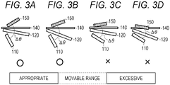
- Figs. 3A to 3D illustrate movable ranges of the aerial image 150 when the display 110 and the beam-splitter 120 are moved.
- Figs. 3A and 3B illustrate the aerial image 150 when the beam-splitter 120 is moved in a state where an inclination angle of the display is made relatively small. In this case, ⁇ is 90 degrees or more, and the aerial image 150 is appropriately movable.
- Figs. 3C and 3D illustrate the aerial image 150 when the beam-splitter 120 is moved in a state where the inclination angle of the display is made larger than that in Figs. 3A and 3B .
- the aerial image 150 is considerably inclined toward the table 140, and ⁇ is less than 90 degrees. In this case, the aerial image 150 is excessively movable.
- FIG. 4A illustrates an example of an angle adjustment mechanism of the present embodiment.
- An angle adjustment mechanism 160 includes an extensible link 170 that connects the display 110 and the beam-splitter 120.
- One end of the link 170 is rotatably and slidably connected in a groove formed along a side of the display 110, and the other end is rotatably and slidably connected in a groove formed along a side of the beam-splitter 120.
- the angle adjustment mechanism 200 rotates both the display 110 and the beam-splitter 120 in conjunction with each other so as to satisfy the relationship shown in the mathematical expression (2), adjusts ⁇ BS and ⁇ Display, and moves the aerial image 150.
- a movable range ( ⁇ Aerial) of the aerial image 150 is assumed to be 0° to 60° as illustrated in the table of Fig. 4E .
- This table illustrates the relationship between the inclination angle ( ⁇ BS) of the beam-splitter 120 and the inclination angle ( ⁇ Display) of the display 110 when ⁇ Aerial is set according to the mathematical expression (2).
- the angle adjustment mechanism 160 may separately rotate or move the beam-splitter 120 and the display 110 by independent mechanisms.
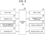
- FIG. 5 is a block diagram illustrating a configuration of a display device of the present embodiment.
- a display device 200 includes an input unit 210 that receives an input from the user, an imaging unit 220, a seat information acquisition unit 230, a storage unit 240, a display unit 250, a beam-splitter drive unit 260, a display drive unit 270, a sound output unit 280, and a control unit 290.
- the display device 200 of the present embodiment is mounted on a vehicle, for example.
- the imaging unit 220 captures a space inside the vehicle and provides captured image data to the control unit 290.
- the seat information acquisition unit 230 acquires information regarding the vehicle. Seat information includes, for example, a seat position of a seat, an inclination angle of a backrest, and the like.
- the storage unit 240 stores various data, application software, and the like necessary for the display device 200. For example, image data to be displayed on the display 110, sound data output from the sound output unit 280, and the like are stored.
- the display unit 250 includes the display 110, the beam-splitter 120, the retro-reflective member 130, the table 140, and the like as illustrated in Fig. 2 .
- the beam-splitter drive unit 260 varies the inclination angle of the beam-splitter 120.
- the beam-splitter drive unit 260 drives a motor connected to the beam-splitter 120 to vary the inclination angle of the beam-splitter 120.
- the display drive unit 270 varies the inclination angle of the display 110.
- the display drive unit 270 drives a motor connected to the display to vary the inclination angle of the display.
- the sound output unit 280 outputs, for example, sound corresponding to an image displayed by the display unit 250.
- the control unit 290 controls the image displayed by the display unit 250 and controls the beam-splitter drive unit 260 and the display drive unit 270.
- control unit 290 estimates an optimum angle of the aerial image when observed from the viewpoint of the user, and controls the beam-splitter drive unit 260 and the display drive unit 270 on the basis of the estimated optimum angle to implement ⁇ ⁇ 90°.
- the control unit 290 analyzes the image data captured by the imaging unit 220 and calculates the viewpoint (three-dimensional coordinate position) of the user.
- the viewpoint (eye point) is a center position of left and right eyes.
- an initially set mounting position (height, angle ( ⁇ Display), and the like) of the display 110 and a mounting position of the beam-splitter 120 are known.
- the control unit 290 estimates the optimum angle ( ⁇ Aerial) of the aerial image 150 for viewing the aerial image 150 in a vertical direction from the calculated viewpoint.
- angles at which the beam-splitter 120 and the display 110 are rotated are calculated on the basis of the estimated optimum angle so as to satisfy the mathematical expressions (1) and (2), and the beam-splitter drive unit 260 and the display drive unit 270 are controlled according to the calculated angles.
- control unit 290 may calculate the viewpoint of the user using the seat information acquired from the seat information acquisition unit 230 and standard body information (for example, a sitting height, a height of the head when the user sits on a seat, and the like) prepared in advance in the storage unit 240.
- standard body information for example, a sitting height, a height of the head when the user sits on a seat, and the like
- the viewpoint of the user is calculated, the optimum angle ( ⁇ Aerial) of the aerial image is estimated from the calculated viewpoint, and the angles at which the beam-splitter 120 and the display 110 are rotated are calculated on the basis of the estimated optimum angle, whereby the user can automatically adjust ⁇ BS and ⁇ Display without any operation. As a result, the user can observe the aerial image having a floating feeling.
- ⁇ BS and ⁇ Display are automatically adjusted.
- the present embodiment is not limited thereto, and for example, the user may input an instruction for adjusting ⁇ BS or the ⁇ Display from the input unit 210.
- the aerial image 150 is generated using the beam-splitter 120 and the retro-reflective member 130
- a polarization beam-splitter may be used instead of the beam-splitter 120, and a ⁇ /4 plate may be arranged on the upper surface side of the retro-reflective member 130.
- the polarization beam-splitter reflects light from the display 110, and the ⁇ /4 plate allows the light reflected by the polarization beam-splitter to enter the plate and transmits the incident light with a phase difference ⁇ /2 (90 degrees).
- the retro-reflective member 130 reflects the light transmitted through the ⁇ /4 plate in the same direction as the incident light.
- the light transmitted through the ⁇ /4 plate has a phase difference ⁇ from the light incident on the ⁇ /4 plate.
- the light incident on the ⁇ /4 plate is linearly polarized light
- the light becomes circularly polarized light (or elliptically polarized light) when passing through the ⁇ /4 plate
- the circularly polarized light becomes circularly polarized light in an opposite direction
- this circularly polarized light in the opposite direction passes through the ⁇ /4 plate
- the circularly polarized light becomes linearly polarized light in a direction 180 degrees different from the original linearly polarized light.
- a target height of an observer is 130 cm to 190 cm.
- 130 cm is an average height of elementary school students, and 190 cm covers the heights of most adults.
- Fig. 6 illustrates eye points of the adult and the elementary school student.
- a method of calculating optimum values of a desk and a chair based on ergonomics is as follows.
- the height of a seat surface of the chair the height ⁇ 0 .25-1
- the height of the desk the height ⁇ 0 .25-1 + the height ⁇ 0 .183-1
- the average height of Japanese adults is about 165 cm.
- the seat height of the chair is 39 cm, and the height of the desk is 68 cm.
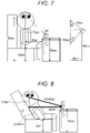
- Fig. 7 is a diagram illustrating a calculation example of the optimum angle ( ⁇ Aerial) of the aerial image from the eye point.
- the optimum angle of the aerial image is calculated by the following equation, where the sitting height of the average adult is 89 cm, the seat height of the chair is 39 cm, the height of the eye point from a ground contact surface of the chair is 118 cm, the height of the desk is 68 cm, and a minimum required distance between the desk and the observer is 45 cm, as illustrated in the drawing.
- ⁇ Aerial cos the eye point ⁇ a horizontal distance of the aerial image / the eye point ⁇ an actual distance of the aerial image
- ⁇ Aerial is 48 degrees when the height of the eye point is 118 cm.
- ⁇ Aerial is 53 degrees in the case where the height of the eye point is 130 cm that is the maximum value, and ⁇ Aerial is 35 degrees in the case where the height of the eye point is 100 cm that is the minimum value.
- ⁇ ⁇ 180° - (20° + 48°) ⁇ 112° of the mathematical expression (1) is obtained, and ⁇ > 90° can be obtained.
- Fig. 8 is a diagram illustrating a calculation example of the optimum angle ( ⁇ Aerial) of the aerial image when the backrest of the seat is inclined.
- the optimum angle of the aerial image is calculated by the following equation, where the sitting height of the average adult is 89 cm, the seat height of the chair is 39 cm, the inclination angle of the backrest is 45°, the desk height is 68 cm, and the minimum required distance between the desk and the observer is 45 cm.
- the optimum angle of the aerial image becomes small, and thus, as the movable range of the aerial image, a range from 0° to 20° is required as illustrated in Fig. 9 .
- the picture of the display 110 does not enter the field of view of the user even if the beam-splitter 120 is not moved.
- the movable range of the aerial image can be expanded as compared with a case where only the display is movable. Further, space saving of the housing can be expected by minimizing the movement of the display. Further, for children to adults with different eye points or users with different physical characteristics, it is possible to observe the aerial image with a floating feeling that the picture of the display does not enter.
Landscapes
- Physics & Mathematics (AREA)
- General Physics & Mathematics (AREA)
- Optics & Photonics (AREA)
- Engineering & Computer Science (AREA)
- Multimedia (AREA)
- Signal Processing (AREA)
- Testing, Inspecting, Measuring Of Stereoscopic Televisions And Televisions (AREA)
- Devices For Indicating Variable Information By Combining Individual Elements (AREA)
Abstract
Description
- The present invention relates to a display device that displays an image in the air using retro-reflection.
- Aerial imaging using retro-reflection (AIRR) is known (for example,
JP 2017-107165 A JP 2018-81138 A JP 2019-66833 A JP 2019-101055 A JP 2013-190448 A - In a case where an AIRR display device is a desk type, a movable aerial image (or aerial picture) is important as a function thereof. By moving the aerial image, it can be expected that a viewing angle at which a user can observe the aerial image is widened, and a physical limitation of the user is greatly improved. The display device of
JP 2013-190448 A - When the aerial image and the display overlap, a picture of the display enters the aerial image, and a floating feeling of the picture, which is a characteristic of the aerial image, is impaired.
Fig. 1 is a schematic cross-sectional view illustrating a configuration of a conventional desk-type display device. Adisplay device 10 includes a display (light source) 20 having a screen capable of displaying an image, a beam-splitter 30, a retro-reflective member 40, and a table 50 made of transparent glass or the like installed in a housing. - A part of light emitted from the
display 20 is reflected by the beam-splitter 30, reflected light of the light is incident on the concave retro-reflective member 40, incident light of the reflected light is reflected by the retro-reflective member 40 in the same direction as the incident light, and a part of reflected light of the incident light is transmitted through the beam-splitter 30 and the table 50 and reimaged, so that theaerial image 60 is displayed. Theaerial image 60 is generated at a position symmetrical to thedisplay 20 with respect to the surface of the beam-splitter 30. Theaerial image 60 that can be observed by a user is limited to a range in which the retro-reflective member 40 can be viewed from a viewpoint U of the user via the beam-splitter 30. - As illustrated in the drawing, when the
display 20 enters the field of view from a viewpoint U of the user, the user observes theaerial image 60 and animage 22 of thedisplay 20 in an overlapping manner, and the floating feeling of theaerial image 60 is impaired. - An object of the present invention is to provide a display device having a function of preventing an image of a display from entering an aerial image.
- The invention relates to a display device according to the appended claims. Embodiments are disclosed in the dependent claims.
- A display device according to an aspect of the present invention is capable of displaying an aerial image using retro-reflection, and includes a display capable of displaying an image; a beam-splitter configured to reflect light emitted from the display; a retro-reflective member configured to reflect the light from the beam-splitter in a same direction as incident light; a first variable unit configured to vary an inclination angle of the display; and a second variable unit configured to vary an inclination angle of the beam-splitter.
- In an embodiment, the first variable unit and the second variable unit satisfy Δθ = 180 - (ΔAerial + ΔDisplay) ≥ 90 degrees, where the inclination angle of the display is denoted by ΔDisplay, an inclination angle of the aerial image generated at a position symmetric to the display with respect to the beam-splitter is denoted by ΔAerial, and an angle formed by the aerial image and the display is denoted by Δθ. In an embodiment, the first variable unit and the second variable unit satisfy ΔAerial = ΔBS × 2 + ΔDisplay, where the inclination angle of the beam-splitter is denoted by ΔBS. In an embodiment, the first variable unit includes a mechanism that interlocks with the second variable unit. In an embodiment, the display device further includes a control unit configured to control the first variable unit and the second variable unit such that the image of the display does not enter a field of view of a user when the aerial image is observed from a vertical direction. In an embodiment, the control unit calculates a viewpoint of the user, estimates an optimum angle when observing the aerial image on a basis of the calculated viewpoint, and controls the first variable unit and the second variable unit on a basis of the estimated optimum angle.
- According to the present invention, since the beam-splitter and the display are made movable, a movable range of the aerial image can be expanded, whereby the aerial image having a floating feeling can be observed from eye points of various users. In particular, by moving the beam-splitter having high angle dependence of the aerial image, it is possible to expand the movable range of the aerial image while suppressing movement of the display.
-
Fig. 1 is a schematic cross-sectional view illustrating a configuration of a conventional display device. -
Fig. 2 is a schematic cross-sectional view of a display device according to an embodiment of the present invention. -
Figs. 3A to 3D are views for describing movement of an aerial image when a beam-splitter and a display of the display device according to the embodiment of the present invention are moved. -
Figs. 4A to 4E are views and a table illustrating a configuration example of an angle adjustment mechanism that connects and moves the beam-splitter and the display of the display device according to the embodiment of the present invention. -
Fig. 5 is a block diagram of a configuration example of an in-vehicle display device according to another embodiment of the present invention. -
Fig. 6 is tables for describing a demonstration example of the display device according to the embodiment of the present invention. -
Fig. 7 is a diagram for describing a demonstration example of the display device according to the embodiment of the present invention. -
Fig. 8 is a diagram for describing a demonstration example of the display device according to the embodiment of the present invention. -
Fig. 9 is a diagram for describing a demonstration example of the display device according to the embodiment of the present invention. - A display device of embodiments of the present invention displays an aerial image or an aerial picture using retro-reflection in a three-dimensional space without wearing special glasses or the like. The drawings to be referred to in the description of the following embodiments include exaggerated display in order to facilitate understanding of the invention, and do not directly represent the shape and scale of an actual product.
- Next, embodiments of the present invention will be described in detail below.
Fig. 2 is a schematic cross-sectional view illustrating a configuration of the display device according to an embodiment of the present invention. Adisplay device 100 of the present embodiment includes adisplay 110 as a light source, a beam-splitter 120, a retro-reflective member 130, and a table 140 disposed on the top of a housing (casing) constituting a desk. Thedisplay device 100 of the present embodiment can move the beam-splitter 120 and thedisplay 110, thereby changing a position or an angle at which anaerial image 150 is displayed. - The
display 110 includes ascreen 112 for displaying an image or a picture, and emits light from thescreen 112 at a constant emission angle or radiation angle. Thedisplay 110 is not particularly limited, and for example, a liquid crystal display, an organic EL display, a projection projector, a light emitting diode, a laser diode, or the like can be used. - The
display 110 is rotatable about an end of the display as a fulcrum such that an inclination angle of thescreen 112 changes with respect to a reference plane P of the housing. The reference plane P is, for example, a vertical plane. A mechanism for changing the inclination angle of thedisplay 110 is not particularly limited, but for example, thedisplay 110 may be rotated by a motor or may be rotated using a link mechanism or the like. Here, an angle formed by the reference plane P and a principal plane (screen 112) of thedisplay 110 is denoted by ΔDisplay. - The table 140 is disposed on, for example, the top of the desk-type housing. The table 140 is a transparent plate-like member made of glass, plastic, or the like, and is fixed such that a principal plane of the table is located at approximately 90 degrees with respect to the reference plane P.
- The beam-
splitter 120 is disposed below the table 140. The beam-splitter 120 is a translucent optical member that separates incident light into reflected light and transmitted light, and reflects a part of light emitted from thescreen 112 of thedisplay 110 toward the retro-reflective member. Note that the beam-splitter 120 may be a half mirror in which an amount of the reflected light is equal to an amount of the transmitted light. - The beam-
splitter 120 is rotatable about an end of the beam-splitter as a fulcrum such that an inclination angle of a principal plane changes with respect to the reference plane P. A mechanism for changing an inclination angle of the beam-splitter 120 is not particularly limited, but for example, the beam-splitter 120 may be rotated by a motor or may be rotated using a link mechanism or the like. Here, an angle formed by the principal plane of the table 140 and the principal plane of the beam-splitter 120 is denoted by ΔBS. - The retro-
reflective member 130 is disposed below thedisplay 110. The retro-reflective member 130 is an optical member that reflects light in the same direction as the incident light, and the configuration thereof is not particularly limited but is configured by, for example, a prismatic retro-reflective element such as a triangular pyramid retro-reflective element or a full cube corner retro-reflective element, or a bead retro-reflective element. The retro-reflective member 130 is configured as, for example, a concave mirror, and reflects light incident from the beam-splitter 120 toward the beam-splitter 120. - The
aerial image 150 is generated at a position symmetrical to thedisplay 110 with respect to the principal plane of the beam-splitter 120. Here, an angle formed by a principal plane of theaerial image 150 and the reference plane P is denoted by ΔAerial, and an angle formed by the principal plane of theaerial image 150 and the principal plane of thedisplay 110 is denoted by Δθ. - The
aerial image 150 that can be observed by a user is limited to a range in which the retro-reflective member 130 can be viewed from the viewpoint U of the user via the beam-splitter 120. Further, the optimum angle or direction for the user to observe theaerial image 150 is a direction in which theaerial image 150 is viewed from directly above, that is, a direction perpendicular to the principal plane of theaerial image 150. When thedisplay 110 enters the field of view viewed from this direction of the viewpoint, the image or picture of thedisplay 110 enters theaerial image 150, and the floating feeling of theaerial image 150 is lost. - In the present embodiment, to prevent the
display 110 from entering the field of view of the user, an angle Δθ formed by theaerial image 150 and thedisplay 110 is set to 90 degrees or more. - The relationship at this time is shown in mathematical expression (1).

- When Δθ is 90 degrees or more, the user cannot view the image on the
screen 112 of thedisplay 110. - ΔDisplay is minimized to satisfy the mathematical expression (1). Since the purpose is to expand a movable range of ΔAerial, it is effective to move the beam-
splitter 120. The relationship among ΔAerial, ΔBS, and ΔDisplay when the beam-splitter 120 is moved is shown in mathematical expression (2).
- As shown in the mathematical expression (2), the movement of the beam-
splitter 120 can make the movement of theaerial image 150 larger than the movement of thedisplay 110 does, and the movement of the ΔDisplay can be suppressed by ΔBS × 2. By moving the beam-splitter 120, it is possible to expand the movable range of theaerial image 150 and implement the mathematical expression (1) while minimizing the movement of thedisplay 110. Suppressing the movement of thedisplay 110 also leads to space saving of the housing. -
Figs. 3A to 3D illustrate movable ranges of theaerial image 150 when thedisplay 110 and the beam-splitter 120 are moved.Figs. 3A and 3B illustrate theaerial image 150 when the beam-splitter 120 is moved in a state where an inclination angle of the display is made relatively small. In this case, Δθ is 90 degrees or more, and theaerial image 150 is appropriately movable.Figs. 3C and 3D illustrate theaerial image 150 when the beam-splitter 120 is moved in a state where the inclination angle of the display is made larger than that inFigs. 3A and 3B . Theaerial image 150 is considerably inclined toward the table 140, and Δθ is less than 90 degrees. In this case, theaerial image 150 is excessively movable. -
Fig. 4A illustrates an example of an angle adjustment mechanism of the present embodiment. Anangle adjustment mechanism 160 includes anextensible link 170 that connects thedisplay 110 and the beam-splitter 120. One end of thelink 170 is rotatably and slidably connected in a groove formed along a side of thedisplay 110, and the other end is rotatably and slidably connected in a groove formed along a side of the beam-splitter 120. Theangle adjustment mechanism 200 rotates both thedisplay 110 and the beam-splitter 120 in conjunction with each other so as to satisfy the relationship shown in the mathematical expression (2), adjusts ΔBS and ΔDisplay, and moves theaerial image 150. - As an example, a movable range (ΔAerial) of the
aerial image 150 is assumed to be 0° to 60° as illustrated in the table ofFig. 4E . This table illustrates the relationship between the inclination angle (ΔBS) of the beam-splitter 120 and the inclination angle (ΔDisplay) of thedisplay 110 when ΔAerial is set according to the mathematical expression (2). Further,Figs. 4A to 4D illustrate examples in which ΔAerial = 0°, ΔAerial = 10°, ΔAerial = 30°, and ΔAerial = 60° are set according to ΔBS and ΔDisplay defined in the table. For example, when ΔAerial is set to 60°, ΔBS = 15° and ΔDisplay = 30° are adjusted. - In these examples, when ΔAerial = 60° illustrated in
Fig. 4D , the condition of Δθ ≥ 90° defined in the mathematical expression (1) is satisfied. That is,
- The inclination angles of ΔBS and ΔDisplay defined in the table of
Fig. 4E are merely examples, and other inclination angles may be used. For example, when ΔAerial is set to 30°, ΔBS = 10° and ΔDisplay = 10° may be set according to the mathematical expression (2), and when ΔAerial is set to 50°, ΔBS = 20° and ΔDisplay = 10° may be set. Further, in the above embodiment, an example in which theangle adjustment mechanism 160 interlocks the beam-splitter 120 and thedisplay 110 has been described but this is an example, and theangle adjustment mechanism 160 may separately rotate or move the beam-splitter 120 and thedisplay 110 by independent mechanisms. - Next, another embodiment of the present embodiment will be described.
Fig. 5 is a block diagram illustrating a configuration of a display device of the present embodiment. Adisplay device 200 includes aninput unit 210 that receives an input from the user, animaging unit 220, a seatinformation acquisition unit 230, astorage unit 240, adisplay unit 250, a beam-splitter drive unit 260, adisplay drive unit 270, asound output unit 280, and acontrol unit 290. - The
display device 200 of the present embodiment is mounted on a vehicle, for example. Theimaging unit 220 captures a space inside the vehicle and provides captured image data to thecontrol unit 290. The seatinformation acquisition unit 230 acquires information regarding the vehicle. Seat information includes, for example, a seat position of a seat, an inclination angle of a backrest, and the like. Thestorage unit 240 stores various data, application software, and the like necessary for thedisplay device 200. For example, image data to be displayed on thedisplay 110, sound data output from thesound output unit 280, and the like are stored. - The
display unit 250 includes thedisplay 110, the beam-splitter 120, the retro-reflective member 130, the table 140, and the like as illustrated inFig. 2 . The beam-splitter drive unit 260 varies the inclination angle of the beam-splitter 120. For example, the beam-splitter drive unit 260 drives a motor connected to the beam-splitter 120 to vary the inclination angle of the beam-splitter 120. Thedisplay drive unit 270 varies the inclination angle of thedisplay 110. For example, thedisplay drive unit 270 drives a motor connected to the display to vary the inclination angle of the display. Thesound output unit 280 outputs, for example, sound corresponding to an image displayed by thedisplay unit 250. Thecontrol unit 290 controls the image displayed by thedisplay unit 250 and controls the beam-splitter drive unit 260 and thedisplay drive unit 270. - In a certain mode, the
control unit 290 estimates an optimum angle of the aerial image when observed from the viewpoint of the user, and controls the beam-splitter drive unit 260 and thedisplay drive unit 270 on the basis of the estimated optimum angle to implement Δθ ≥ 90°. - To estimate the optimum angle of the aerial image, the
control unit 290 analyzes the image data captured by theimaging unit 220 and calculates the viewpoint (three-dimensional coordinate position) of the user. The viewpoint (eye point) is a center position of left and right eyes. Further, an initially set mounting position (height, angle (ΔDisplay), and the like) of thedisplay 110 and a mounting position of the beam-splitter 120 are known. In view of the configuration that theaerial image 150 is generated at the position symmetrical with respect to the principal plane of the beam-splitter, thecontrol unit 290 estimates the optimum angle (ΔAerial) of theaerial image 150 for viewing theaerial image 150 in a vertical direction from the calculated viewpoint. Then, the angles at which the beam-splitter 120 and thedisplay 110 are rotated are calculated on the basis of the estimated optimum angle so as to satisfy the mathematical expressions (1) and (2), and the beam-splitter drive unit 260 and thedisplay drive unit 270 are controlled according to the calculated angles. - For example, when 40° is estimated as the optimum angle (ΔAerial) of the aerial image, the
control unit 290 calculates ΔBS = 10° and ΔDisplay = 20° from the mathematical expression (2) or the table ofFig. 4E , and controls the driving of the beam-splitter drive unit 260 and thedisplay drive unit 270 on the basis of the calculated values. - Further, as another method of calculating the viewpoint of the user, the
control unit 290 may calculate the viewpoint of the user using the seat information acquired from the seatinformation acquisition unit 230 and standard body information (for example, a sitting height, a height of the head when the user sits on a seat, and the like) prepared in advance in thestorage unit 240. - As described above, according to the present embodiment, the viewpoint of the user is calculated, the optimum angle (ΔAerial) of the aerial image is estimated from the calculated viewpoint, and the angles at which the beam-
splitter 120 and thedisplay 110 are rotated are calculated on the basis of the estimated optimum angle, whereby the user can automatically adjust ΔBS and ΔDisplay without any operation. As a result, the user can observe the aerial image having a floating feeling. - In the above embodiment, ΔBS and ΔDisplay are automatically adjusted. However, the present embodiment is not limited thereto, and for example, the user may input an instruction for adjusting ΔBS or the ΔDisplay from the
input unit 210. - In the above embodiment, an example in which the
aerial image 150 is generated using the beam-splitter 120 and the retro-reflective member 130 has been described. However, a polarization beam-splitter may be used instead of the beam-splitter 120, and a λ/4 plate may be arranged on the upper surface side of the retro-reflective member 130. The polarization beam-splitter reflects light from thedisplay 110, and the λ/4 plate allows the light reflected by the polarization beam-splitter to enter the plate and transmits the incident light with a phase difference π/2 (90 degrees). The retro-reflective member 130 reflects the light transmitted through the λ/4 plate in the same direction as the incident light. When the light reflected by the retro-reflective member 130 is transmitted through the λ/4 plate again, the phase difference π/2 is provided. Thus, the light transmitted through the λ/4 plate has a phase difference π from the light incident on the λ/4 plate. For example, in a case where the light incident on the λ/4 plate is linearly polarized light, the light becomes circularly polarized light (or elliptically polarized light) when passing through the λ/4 plate, when the circularly polarized light is retro-reflected an odd number of times by the retro-reflective member 130, the circularly polarized light becomes circularly polarized light in an opposite direction, and when this circularly polarized light in the opposite direction passes through the λ/4 plate, the circularly polarized light becomes linearly polarized light in a direction 180 degrees different from the original linearly polarized light. In this way, when the light transmitted through the λ/4 plate is incident on the polarization beam-splitter, most of the light is transmitted through the polarization beam-splitter, the transmitted light forms an image, and the aerial image is formed. - Next, a specific demonstration example in the display device of the present embodiment will be described. A target height of an observer is 130 cm to 190 cm. 130 cm is an average height of elementary school students, and 190 cm covers the heights of most adults.
Fig. 6 illustrates an average sitting height of the adult and the elementary school student. Further, the eye point (viewpoint) is denoted by the eye point = the sitting height -10 cm.Fig. 6 illustrates eye points of the adult and the elementary school student. - Next, a method of calculating optimum values of a desk and a chair based on ergonomics is as follows.


- For example, the average height of Japanese adults is about 165 cm. In this case, the seat height of the chair is 39 cm, and the height of the desk is 68 cm.
-
Fig. 7 is a diagram illustrating a calculation example of the optimum angle (ΔAerial) of the aerial image from the eye point. The optimum angle of the aerial image is calculated by the following equation, where the sitting height of the average adult is 89 cm, the seat height of the chair is 39 cm, the height of the eye point from a ground contact surface of the chair is 118 cm, the height of the desk is 68 cm, and a minimum required distance between the desk and the observer is 45 cm, as illustrated in the drawing.
- According to this mathematical expression, ΔAerial is 48 degrees when the height of the eye point is 118 cm.
- Incidentally, ΔAerial is 53 degrees in the case where the height of the eye point is 130 cm that is the maximum value, and ΔAerial is 35 degrees in the case where the height of the eye point is 100 cm that is the minimum value.
- In the case where the optimum angle of the aerial image is ΔAerial = 48°, Δθ = 180° - (48° + 48°) = 84° in the mathematical expression (1), and Δθ < 90° is obtained. Here, the beam-
splitter 120 is horizontal (ΔBS = 0°) and the ΔDisplay of thedisplay 110, which is symmetrical with respect to the principal plane of the beam-splitter 120, is 48°. In this state, the picture of thedisplay 110 enters the field of view of the user. - Therefore, in the present embodiment, the table of
Fig. 4E is referred to and ΔAerial = 50 closest to the optimum angle is referred to, and the angle of the beam-splitter 120 is adjusted to ΔBS = 15° and the angle of thedisplay 110 is adjusted to ΔDisplay = 20°. As a result, Δθ ≈ 180° - (20° + 48°) ≈ 112° of the mathematical expression (1) is obtained, and Δθ > 90° can be obtained. -
Fig. 8 is a diagram illustrating a calculation example of the optimum angle (ΔAerial) of the aerial image when the backrest of the seat is inclined. As illustrated in the drawing, the optimum angle of the aerial image is calculated by the following equation, where the sitting height of the average adult is 89 cm, the seat height of the chair is 39 cm, the inclination angle of the backrest is 45°, the desk height is 68 cm, and the minimum required distance between the desk and the observer is 45 cm.
- In the case where the backrest is inclined, the optimum angle of the aerial image becomes small, and thus, as the movable range of the aerial image, a range from 0° to 20° is required as illustrated in
Fig. 9 . In this case, the picture of thedisplay 110 does not enter the field of view of the user even if the beam-splitter 120 is not moved. - As described above, according to the display device of the present embodiment, by moving the beam-
splitter 120 having high angle dependency of ΔAerial, the movable range of the aerial image can be expanded as compared with a case where only the display is movable. Further, space saving of the housing can be expected by minimizing the movement of the display. Further, for children to adults with different eye points or users with different physical characteristics, it is possible to observe the aerial image with a floating feeling that the picture of the display does not enter. - Although the preferred embodiments of the present invention have been described in detail above, the present invention is not limited to the specific embodiments, and various modifications and changes can be made within the scope of the gist of the invention set forth in the claims.
-
- 100
- Display device
- 110
- Display
- 120
- Beam-splitter
- 130
- Retro-reflective member
- 140
- Table
- 150
- Aerial image
- 160
- Angle adjustment mechanism
- 170
- Link
Claims (6)
- A display device (100) capable of displaying an aerial image (150) using retro-reflection, the display device (100) comprising:a display (110) capable of displaying an image;a beam-splitter (120) configured to reflect light emitted from the display (110); anda retro-reflective member (130) configured to reflect the light from the beam-splitter (120) in a same direction as incident light,the display device (100) being characterized bya first variable unit configured to vary an inclination angle of the display (110); anda second variable unit configured to vary an inclination angle of the beam-splitter (120).
- The display device (100) according to claim 1, whereinthe first variable unit and the second variable unit satisfy
 where the inclination angle of the display (110) is denoted by ΔDisplay, an inclination angle of the aerial image (150) generated at a position symmetric to the display (110) with respect to the beam-splitter (120) is denoted by ΔAerial, and an angle formed by the aerial image (150) and the display (110) is denoted by Δθ.
 - The display device (100) according to claim 2, whereinthe first variable unit and the second variable unit satisfy
 where the inclination angle of the beam-splitter (120) is denoted by ΔBS.
 - The display device (100) according to any of claims 1-3, wherein the first variable unit includes a mechanism (160) that interlocks with the second variable unit.
- The display device (100) according to any one of claims 1 to 4, further comprising:
a control unit (290) configured to control the first variable unit and the second variable unit such that the image of the display (110) does not enter a field of view of a user when the aerial image (150) is observed from a vertical direction. - The display device (100) according to claim 5, wherein the control unit (290) is configured to calculate a viewpoint of the user, to estimate an optimum angle when observing the aerial image (150) on a basis of the calculated viewpoint, and to control the first variable unit and the second variable unit on a basis of the estimated optimum angle.
Applications Claiming Priority (1)
| Application Number | Priority Date | Filing Date | Title |
|---|---|---|---|
| JP2021087518A JP7572139B2 (en) | 2021-05-25 | 2021-05-25 | Display device |
Publications (2)
| Publication Number | Publication Date |
|---|---|
| EP4095590A1 true EP4095590A1 (en) | 2022-11-30 |
| EP4095590B1 EP4095590B1 (en) | 2025-02-19 |
Family
ID=81748695
Family Applications (1)
| Application Number | Title | Priority Date | Filing Date |
|---|---|---|---|
| EP22173839.6A Active EP4095590B1 (en) | 2021-05-25 | 2022-05-17 | Display device |
Country Status (4)
| Country | Link |
|---|---|
| US (1) | US12196977B2 (en) |
| EP (1) | EP4095590B1 (en) |
| JP (1) | JP7572139B2 (en) |
| CN (1) | CN115390268A (en) |
Families Citing this family (4)
| Publication number | Priority date | Publication date | Assignee | Title |
|---|---|---|---|---|
| JP2024111912A (en) | 2023-02-07 | 2024-08-20 | アルプスアルパイン株式会社 | Input display device |
| WO2024252907A1 (en) * | 2023-06-08 | 2024-12-12 | マクセル株式会社 | Aerial image display device |
| WO2025187392A1 (en) * | 2024-03-05 | 2025-09-12 | マクセル株式会社 | Aerial floating image display apparatus |
| JP2025158795A (en) | 2024-04-05 | 2025-10-17 | アルプスアルパイン株式会社 | display device |
Citations (7)
| Publication number | Priority date | Publication date | Assignee | Title |
|---|---|---|---|---|
| JP2013190448A (en) | 2010-06-30 | 2013-09-26 | Sharp Corp | Display device |
| JP2017107165A (en) | 2015-12-07 | 2017-06-15 | 国立大学法人宇都宮大学 | Display device and display method of aerial image |
| JP2018031925A (en) * | 2016-08-25 | 2018-03-01 | パナソニックIpマネジメント株式会社 | Aerial display device |
| JP2018081138A (en) | 2016-11-14 | 2018-05-24 | 日本カーバイド工業株式会社 | Image display unit |
| JP2019066833A (en) | 2017-09-29 | 2019-04-25 | 日本カーバイド工業株式会社 | Image display device |
| JP2019101055A (en) | 2017-11-28 | 2019-06-24 | コニカミノルタ株式会社 | Aerial video display device |
| US20190285904A1 (en) * | 2016-05-16 | 2019-09-19 | Samsung Electronics Co., Ltd. | Three-dimensional imaging device and electronic device including same |
Family Cites Families (3)
| Publication number | Priority date | Publication date | Assignee | Title |
|---|---|---|---|---|
| US10302954B2 (en) * | 2015-06-12 | 2019-05-28 | Nippon Carbide Industries Co., Inc. | Image display device |
| WO2017099116A1 (en) | 2015-12-07 | 2017-06-15 | 国立大学法人宇都宮大学 | Display device, and display method for aerial image |
| JP2017146564A (en) * | 2016-02-19 | 2017-08-24 | パナソニックIpマネジメント株式会社 | Spatial display device |
-
2021
- 2021-05-25 JP JP2021087518A patent/JP7572139B2/en active Active
-
2022
- 2022-05-12 US US17/742,713 patent/US12196977B2/en active Active
- 2022-05-17 EP EP22173839.6A patent/EP4095590B1/en active Active
- 2022-05-24 CN CN202210569310.XA patent/CN115390268A/en active Pending
Patent Citations (7)
| Publication number | Priority date | Publication date | Assignee | Title |
|---|---|---|---|---|
| JP2013190448A (en) | 2010-06-30 | 2013-09-26 | Sharp Corp | Display device |
| JP2017107165A (en) | 2015-12-07 | 2017-06-15 | 国立大学法人宇都宮大学 | Display device and display method of aerial image |
| US20190285904A1 (en) * | 2016-05-16 | 2019-09-19 | Samsung Electronics Co., Ltd. | Three-dimensional imaging device and electronic device including same |
| JP2018031925A (en) * | 2016-08-25 | 2018-03-01 | パナソニックIpマネジメント株式会社 | Aerial display device |
| JP2018081138A (en) | 2016-11-14 | 2018-05-24 | 日本カーバイド工業株式会社 | Image display unit |
| JP2019066833A (en) | 2017-09-29 | 2019-04-25 | 日本カーバイド工業株式会社 | Image display device |
| JP2019101055A (en) | 2017-11-28 | 2019-06-24 | コニカミノルタ株式会社 | Aerial video display device |
Also Published As
| Publication number | Publication date |
|---|---|
| EP4095590B1 (en) | 2025-02-19 |
| CN115390268A (en) | 2022-11-25 |
| JP7572139B2 (en) | 2024-10-23 |
| US20220382066A1 (en) | 2022-12-01 |
| US12196977B2 (en) | 2025-01-14 |
| JP2022180814A (en) | 2022-12-07 |
Similar Documents
| Publication | Publication Date | Title |
|---|---|---|
| EP4095590B1 (en) | Display device | |
| US11422377B2 (en) | Display device | |
| US10585338B2 (en) | Display device | |
| JP3976040B2 (en) | Stereoscopic image display device | |
| US10185212B1 (en) | Projection display apparatus including eye tracker | |
| US20180284441A1 (en) | Wide field head mounted display | |
| CN115280218B (en) | High-resolution LCD display | |
| CN115053166B (en) | Folded beam low-angle beam scanner | |
| US20130234930A1 (en) | Scanning mirror laser and projector head-up display glasses | |
| US10914956B1 (en) | Tiled display assemblies for artificial reality headset | |
| NO340256B1 (en) | Projection display device and projection display device | |
| WO2020021773A1 (en) | Virtual image display device | |
| CN114450620A (en) | Low tilt pupil relay for near-eye displays | |
| CN110290377B (en) | Display device, display method, and game machine | |
| KR20180107133A (en) | Multi-stripe laser for laser-based projector displays | |
| US11025871B1 (en) | Driving scanning projector display with pulses shorter than pixel duration | |
| US11137597B2 (en) | Image display apparatus | |
| US20180017800A1 (en) | Virtual image display apparatus | |
| US10908418B1 (en) | Naked eye 3D head-up display device with reflective diffuser sheet | |
| WO2023112197A1 (en) | Aerial image display device | |
| JP2014119687A (en) | Screen device and display device | |
| JP7294643B2 (en) | display device | |
| Kintz | Autostereoscopic properties of spherical panoramic virtual displays | |
| Kishore et al. | Laser scanning 3D display with dynamic exit pupil | |
| WO2017145324A1 (en) | Helmet-mounted display |
Legal Events
| Date | Code | Title | Description |
|---|---|---|---|
| PUAI | Public reference made under article 153(3) epc to a published international application that has entered the european phase |
Free format text: ORIGINAL CODE: 0009012 |
|
| STAA | Information on the status of an ep patent application or granted ep patent |
Free format text: STATUS: THE APPLICATION HAS BEEN PUBLISHED |
|
| AK | Designated contracting states |
Kind code of ref document: A1 Designated state(s): AL AT BE BG CH CY CZ DE DK EE ES FI FR GB GR HR HU IE IS IT LI LT LU LV MC MK MT NL NO PL PT RO RS SE SI SK SM TR |
|
| STAA | Information on the status of an ep patent application or granted ep patent |
Free format text: STATUS: REQUEST FOR EXAMINATION WAS MADE |
|
| 17P | Request for examination filed |
Effective date: 20230523 |
|
| RBV | Designated contracting states (corrected) |
Designated state(s): AL AT BE BG CH CY CZ DE DK EE ES FI FR GB GR HR HU IE IS IT LI LT LU LV MC MK MT NL NO PL PT RO RS SE SI SK SM TR |
|
| GRAP | Despatch of communication of intention to grant a patent |
Free format text: ORIGINAL CODE: EPIDOSNIGR1 |
|
| STAA | Information on the status of an ep patent application or granted ep patent |
Free format text: STATUS: GRANT OF PATENT IS INTENDED |
|
| INTG | Intention to grant announced |
Effective date: 20240923 |
|
| RIC1 | Information provided on ipc code assigned before grant |
Ipc: G02B 30/56 20200101ALI20240913BHEP Ipc: G02B 30/60 20200101ALI20240913BHEP Ipc: H04N 13/346 20180101ALI20240913BHEP Ipc: G02B 30/40 20200101AFI20240913BHEP |
|
| GRAS | Grant fee paid |
Free format text: ORIGINAL CODE: EPIDOSNIGR3 |
|
| GRAA | (expected) grant |
Free format text: ORIGINAL CODE: 0009210 |
|
| STAA | Information on the status of an ep patent application or granted ep patent |
Free format text: STATUS: THE PATENT HAS BEEN GRANTED |
|
| AK | Designated contracting states |
Kind code of ref document: B1 Designated state(s): AL AT BE BG CH CY CZ DE DK EE ES FI FR GB GR HR HU IE IS IT LI LT LU LV MC MK MT NL NO PL PT RO RS SE SI SK SM TR |
|
| P01 | Opt-out of the competence of the unified patent court (upc) registered |
Free format text: CASE NUMBER: APP_2066/2025 Effective date: 20250113 |
|
| REG | Reference to a national code |
Ref country code: GB Ref legal event code: FG4D |
|
| REG | Reference to a national code |
Ref country code: CH Ref legal event code: EP |
|
| REG | Reference to a national code |
Ref country code: IE Ref legal event code: FG4D |
|
| REG | Reference to a national code |
Ref country code: DE Ref legal event code: R096 Ref document number: 602022010687 Country of ref document: DE |
|
| REG | Reference to a national code |
Ref country code: NL Ref legal event code: MP Effective date: 20250219 |
|
| PG25 | Lapsed in a contracting state [announced via postgrant information from national office to epo] |
Ref country code: RS Free format text: LAPSE BECAUSE OF FAILURE TO SUBMIT A TRANSLATION OF THE DESCRIPTION OR TO PAY THE FEE WITHIN THE PRESCRIBED TIME-LIMIT Effective date: 20250519 |
|
| PG25 | Lapsed in a contracting state [announced via postgrant information from national office to epo] |
Ref country code: FI Free format text: LAPSE BECAUSE OF FAILURE TO SUBMIT A TRANSLATION OF THE DESCRIPTION OR TO PAY THE FEE WITHIN THE PRESCRIBED TIME-LIMIT Effective date: 20250219 |
|
| PG25 | Lapsed in a contracting state [announced via postgrant information from national office to epo] |
Ref country code: PL Free format text: LAPSE BECAUSE OF FAILURE TO SUBMIT A TRANSLATION OF THE DESCRIPTION OR TO PAY THE FEE WITHIN THE PRESCRIBED TIME-LIMIT Effective date: 20250219 |
|
| PGFP | Annual fee paid to national office [announced via postgrant information from national office to epo] |
Ref country code: DE Payment date: 20250521 Year of fee payment: 4 |
|
| PG25 | Lapsed in a contracting state [announced via postgrant information from national office to epo] |
Ref country code: ES Free format text: LAPSE BECAUSE OF FAILURE TO SUBMIT A TRANSLATION OF THE DESCRIPTION OR TO PAY THE FEE WITHIN THE PRESCRIBED TIME-LIMIT Effective date: 20250219 |
|
| REG | Reference to a national code |
Ref country code: LT Ref legal event code: MG9D |
|
| PG25 | Lapsed in a contracting state [announced via postgrant information from national office to epo] |
Ref country code: IS Free format text: LAPSE BECAUSE OF FAILURE TO SUBMIT A TRANSLATION OF THE DESCRIPTION OR TO PAY THE FEE WITHIN THE PRESCRIBED TIME-LIMIT Effective date: 20250619 Ref country code: NO Free format text: LAPSE BECAUSE OF FAILURE TO SUBMIT A TRANSLATION OF THE DESCRIPTION OR TO PAY THE FEE WITHIN THE PRESCRIBED TIME-LIMIT Effective date: 20250519 |
|
| PG25 | Lapsed in a contracting state [announced via postgrant information from national office to epo] |
Ref country code: NL Free format text: LAPSE BECAUSE OF FAILURE TO SUBMIT A TRANSLATION OF THE DESCRIPTION OR TO PAY THE FEE WITHIN THE PRESCRIBED TIME-LIMIT Effective date: 20250219 |
|
| PG25 | Lapsed in a contracting state [announced via postgrant information from national office to epo] |
Ref country code: HR Free format text: LAPSE BECAUSE OF FAILURE TO SUBMIT A TRANSLATION OF THE DESCRIPTION OR TO PAY THE FEE WITHIN THE PRESCRIBED TIME-LIMIT Effective date: 20250219 |
|
| PG25 | Lapsed in a contracting state [announced via postgrant information from national office to epo] |
Ref country code: PT Free format text: LAPSE BECAUSE OF FAILURE TO SUBMIT A TRANSLATION OF THE DESCRIPTION OR TO PAY THE FEE WITHIN THE PRESCRIBED TIME-LIMIT Effective date: 20250620 Ref country code: LV Free format text: LAPSE BECAUSE OF FAILURE TO SUBMIT A TRANSLATION OF THE DESCRIPTION OR TO PAY THE FEE WITHIN THE PRESCRIBED TIME-LIMIT Effective date: 20250219 |
|
| PGFP | Annual fee paid to national office [announced via postgrant information from national office to epo] |
Ref country code: FR Payment date: 20250528 Year of fee payment: 4 |
|
| PG25 | Lapsed in a contracting state [announced via postgrant information from national office to epo] |
Ref country code: BG Free format text: LAPSE BECAUSE OF FAILURE TO SUBMIT A TRANSLATION OF THE DESCRIPTION OR TO PAY THE FEE WITHIN THE PRESCRIBED TIME-LIMIT Effective date: 20250219 Ref country code: GR Free format text: LAPSE BECAUSE OF FAILURE TO SUBMIT A TRANSLATION OF THE DESCRIPTION OR TO PAY THE FEE WITHIN THE PRESCRIBED TIME-LIMIT Effective date: 20250520 |
|
| REG | Reference to a national code |
Ref country code: AT Ref legal event code: MK05 Ref document number: 1768820 Country of ref document: AT Kind code of ref document: T Effective date: 20250219 |
|
| PG25 | Lapsed in a contracting state [announced via postgrant information from national office to epo] |
Ref country code: SE Free format text: LAPSE BECAUSE OF FAILURE TO SUBMIT A TRANSLATION OF THE DESCRIPTION OR TO PAY THE FEE WITHIN THE PRESCRIBED TIME-LIMIT Effective date: 20250219 |
|
| PG25 | Lapsed in a contracting state [announced via postgrant information from national office to epo] |
Ref country code: SM Free format text: LAPSE BECAUSE OF FAILURE TO SUBMIT A TRANSLATION OF THE DESCRIPTION OR TO PAY THE FEE WITHIN THE PRESCRIBED TIME-LIMIT Effective date: 20250219 |
|
| PG25 | Lapsed in a contracting state [announced via postgrant information from national office to epo] |
Ref country code: DK Free format text: LAPSE BECAUSE OF FAILURE TO SUBMIT A TRANSLATION OF THE DESCRIPTION OR TO PAY THE FEE WITHIN THE PRESCRIBED TIME-LIMIT Effective date: 20250219 |
|
| PG25 | Lapsed in a contracting state [announced via postgrant information from national office to epo] |
Ref country code: IT Free format text: LAPSE BECAUSE OF FAILURE TO SUBMIT A TRANSLATION OF THE DESCRIPTION OR TO PAY THE FEE WITHIN THE PRESCRIBED TIME-LIMIT Effective date: 20250219 |
|
| PG25 | Lapsed in a contracting state [announced via postgrant information from national office to epo] |
Ref country code: AT Free format text: LAPSE BECAUSE OF FAILURE TO SUBMIT A TRANSLATION OF THE DESCRIPTION OR TO PAY THE FEE WITHIN THE PRESCRIBED TIME-LIMIT Effective date: 20250219 |
|
| PG25 | Lapsed in a contracting state [announced via postgrant information from national office to epo] |
Ref country code: EE Free format text: LAPSE BECAUSE OF FAILURE TO SUBMIT A TRANSLATION OF THE DESCRIPTION OR TO PAY THE FEE WITHIN THE PRESCRIBED TIME-LIMIT Effective date: 20250219 Ref country code: CZ Free format text: LAPSE BECAUSE OF FAILURE TO SUBMIT A TRANSLATION OF THE DESCRIPTION OR TO PAY THE FEE WITHIN THE PRESCRIBED TIME-LIMIT Effective date: 20250219 |
|
| PG25 | Lapsed in a contracting state [announced via postgrant information from national office to epo] |
Ref country code: RO Free format text: LAPSE BECAUSE OF FAILURE TO SUBMIT A TRANSLATION OF THE DESCRIPTION OR TO PAY THE FEE WITHIN THE PRESCRIBED TIME-LIMIT Effective date: 20250219 |
|
| PG25 | Lapsed in a contracting state [announced via postgrant information from national office to epo] |
Ref country code: SK Free format text: LAPSE BECAUSE OF FAILURE TO SUBMIT A TRANSLATION OF THE DESCRIPTION OR TO PAY THE FEE WITHIN THE PRESCRIBED TIME-LIMIT Effective date: 20250219 |
|
| REG | Reference to a national code |
Ref country code: DE Ref legal event code: R097 Ref document number: 602022010687 Country of ref document: DE |
|
| REG | Reference to a national code |
Ref country code: CH Ref legal event code: H13 Free format text: ST27 STATUS EVENT CODE: U-0-0-H10-H13 (AS PROVIDED BY THE NATIONAL OFFICE) Effective date: 20251223 |
|
| PLBE | No opposition filed within time limit |
Free format text: ORIGINAL CODE: 0009261 |
|
| STAA | Information on the status of an ep patent application or granted ep patent |
Free format text: STATUS: NO OPPOSITION FILED WITHIN TIME LIMIT |
|
| PG25 | Lapsed in a contracting state [announced via postgrant information from national office to epo] |
Ref country code: LU Free format text: LAPSE BECAUSE OF NON-PAYMENT OF DUE FEES Effective date: 20250517 |
|
| PG25 | Lapsed in a contracting state [announced via postgrant information from national office to epo] |
Ref country code: CH Free format text: LAPSE BECAUSE OF NON-PAYMENT OF DUE FEES Effective date: 20250531 |
|
| 26N | No opposition filed |
Effective date: 20251120 |
|
| REG | Reference to a national code |
Ref country code: BE Ref legal event code: MM Effective date: 20250531 |
|
| PG25 | Lapsed in a contracting state [announced via postgrant information from national office to epo] |
Ref country code: MC Free format text: LAPSE BECAUSE OF FAILURE TO SUBMIT A TRANSLATION OF THE DESCRIPTION OR TO PAY THE FEE WITHIN THE PRESCRIBED TIME-LIMIT Effective date: 20250219 |
|
| PG25 | Lapsed in a contracting state [announced via postgrant information from national office to epo] |
Ref country code: IE Free format text: LAPSE BECAUSE OF NON-PAYMENT OF DUE FEES Effective date: 20250517 |
|
| PG25 | Lapsed in a contracting state [announced via postgrant information from national office to epo] |
Ref country code: BE Free format text: LAPSE BECAUSE OF NON-PAYMENT OF DUE FEES Effective date: 20250531 |