EP4095467B1 - Shelf assembly and storage cabinet - Google Patents
Shelf assembly and storage cabinet Download PDFInfo
- Publication number
- EP4095467B1 EP4095467B1 EP20916082.9A EP20916082A EP4095467B1 EP 4095467 B1 EP4095467 B1 EP 4095467B1 EP 20916082 A EP20916082 A EP 20916082A EP 4095467 B1 EP4095467 B1 EP 4095467B1
- Authority
- EP
- European Patent Office
- Prior art keywords
- shelf
- shelf assembly
- movement
- plate
- component
- Prior art date
- Legal status (The legal status is an assumption and is not a legal conclusion. Google has not performed a legal analysis and makes no representation as to the accuracy of the status listed.)
- Active
Links
Images




Classifications
-
- F—MECHANICAL ENGINEERING; LIGHTING; HEATING; WEAPONS; BLASTING
- F25—REFRIGERATION OR COOLING; COMBINED HEATING AND REFRIGERATION SYSTEMS; HEAT PUMP SYSTEMS; MANUFACTURE OR STORAGE OF ICE; LIQUEFACTION SOLIDIFICATION OF GASES
- F25D—REFRIGERATORS; COLD ROOMS; ICE-BOXES; COOLING OR FREEZING APPARATUS NOT OTHERWISE PROVIDED FOR
- F25D25/00—Charging, supporting, and discharging the articles to be cooled
- F25D25/02—Charging, supporting, and discharging the articles to be cooled by shelves
-
- F—MECHANICAL ENGINEERING; LIGHTING; HEATING; WEAPONS; BLASTING
- F25—REFRIGERATION OR COOLING; COMBINED HEATING AND REFRIGERATION SYSTEMS; HEAT PUMP SYSTEMS; MANUFACTURE OR STORAGE OF ICE; LIQUEFACTION SOLIDIFICATION OF GASES
- F25D—REFRIGERATORS; COLD ROOMS; ICE-BOXES; COOLING OR FREEZING APPARATUS NOT OTHERWISE PROVIDED FOR
- F25D25/00—Charging, supporting, and discharging the articles to be cooled
- F25D25/02—Charging, supporting, and discharging the articles to be cooled by shelves
- F25D25/024—Slidable shelves
-
- A—HUMAN NECESSITIES
- A47—FURNITURE; DOMESTIC ARTICLES OR APPLIANCES; COFFEE MILLS; SPICE MILLS; SUCTION CLEANERS IN GENERAL
- A47B—TABLES; DESKS; OFFICE FURNITURE; CABINETS; DRAWERS; GENERAL DETAILS OF FURNITURE
- A47B57/00—Cabinets, racks or shelf units, characterised by features for adjusting shelves or partitions
- A47B57/06—Cabinets, racks or shelf units, characterised by features for adjusting shelves or partitions with means for adjusting the height of the shelves
- A47B57/18—Cabinets, racks or shelf units, characterised by features for adjusting shelves or partitions with means for adjusting the height of the shelves consisting of screwbolts as connecting members
-
- A—HUMAN NECESSITIES
- A47—FURNITURE; DOMESTIC ARTICLES OR APPLIANCES; COFFEE MILLS; SPICE MILLS; SUCTION CLEANERS IN GENERAL
- A47B—TABLES; DESKS; OFFICE FURNITURE; CABINETS; DRAWERS; GENERAL DETAILS OF FURNITURE
- A47B57/00—Cabinets, racks or shelf units, characterised by features for adjusting shelves or partitions
- A47B57/06—Cabinets, racks or shelf units, characterised by features for adjusting shelves or partitions with means for adjusting the height of the shelves
-
- A—HUMAN NECESSITIES
- A47—FURNITURE; DOMESTIC ARTICLES OR APPLIANCES; COFFEE MILLS; SPICE MILLS; SUCTION CLEANERS IN GENERAL
- A47B—TABLES; DESKS; OFFICE FURNITURE; CABINETS; DRAWERS; GENERAL DETAILS OF FURNITURE
- A47B96/00—Details of cabinets, racks or shelf units not covered by a single one of groups A47B43/00 - A47B95/00; General details of furniture
- A47B96/02—Shelves
- A47B96/025—Shelves with moving elements, e.g. movable extensions or link elements
-
- A—HUMAN NECESSITIES
- A47—FURNITURE; DOMESTIC ARTICLES OR APPLIANCES; COFFEE MILLS; SPICE MILLS; SUCTION CLEANERS IN GENERAL
- A47F—SPECIAL FURNITURE, FITTINGS, OR ACCESSORIES FOR SHOPS, STOREHOUSES, BARS, RESTAURANTS OR THE LIKE; PAYING COUNTERS
- A47F3/00—Show cases or show cabinets
-
- A—HUMAN NECESSITIES
- A47—FURNITURE; DOMESTIC ARTICLES OR APPLIANCES; COFFEE MILLS; SPICE MILLS; SUCTION CLEANERS IN GENERAL
- A47F—SPECIAL FURNITURE, FITTINGS, OR ACCESSORIES FOR SHOPS, STOREHOUSES, BARS, RESTAURANTS OR THE LIKE; PAYING COUNTERS
- A47F3/00—Show cases or show cabinets
- A47F3/04—Show cases or show cabinets air-conditioned, refrigerated
- A47F3/0482—Details common to both closed and open types
- A47F3/0486—Details common to both closed and open types for charging, displaying or discharging the articles
-
- F—MECHANICAL ENGINEERING; LIGHTING; HEATING; WEAPONS; BLASTING
- F25—REFRIGERATION OR COOLING; COMBINED HEATING AND REFRIGERATION SYSTEMS; HEAT PUMP SYSTEMS; MANUFACTURE OR STORAGE OF ICE; LIQUEFACTION SOLIDIFICATION OF GASES
- F25D—REFRIGERATORS; COLD ROOMS; ICE-BOXES; COOLING OR FREEZING APPARATUS NOT OTHERWISE PROVIDED FOR
- F25D11/00—Self-contained movable devices, e.g. domestic refrigerators
-
- F—MECHANICAL ENGINEERING; LIGHTING; HEATING; WEAPONS; BLASTING
- F25—REFRIGERATION OR COOLING; COMBINED HEATING AND REFRIGERATION SYSTEMS; HEAT PUMP SYSTEMS; MANUFACTURE OR STORAGE OF ICE; LIQUEFACTION SOLIDIFICATION OF GASES
- F25D—REFRIGERATORS; COLD ROOMS; ICE-BOXES; COOLING OR FREEZING APPARATUS NOT OTHERWISE PROVIDED FOR
- F25D25/00—Charging, supporting, and discharging the articles to be cooled
- F25D25/04—Charging, supporting, and discharging the articles to be cooled by conveyors
-
- A—HUMAN NECESSITIES
- A47—FURNITURE; DOMESTIC ARTICLES OR APPLIANCES; COFFEE MILLS; SPICE MILLS; SUCTION CLEANERS IN GENERAL
- A47B—TABLES; DESKS; OFFICE FURNITURE; CABINETS; DRAWERS; GENERAL DETAILS OF FURNITURE
- A47B96/00—Details of cabinets, racks or shelf units not covered by a single one of groups A47B43/00 - A47B95/00; General details of furniture
- A47B96/02—Shelves
- A47B96/027—Cantilever shelves
-
- F—MECHANICAL ENGINEERING; LIGHTING; HEATING; WEAPONS; BLASTING
- F25—REFRIGERATION OR COOLING; COMBINED HEATING AND REFRIGERATION SYSTEMS; HEAT PUMP SYSTEMS; MANUFACTURE OR STORAGE OF ICE; LIQUEFACTION SOLIDIFICATION OF GASES
- F25D—REFRIGERATORS; COLD ROOMS; ICE-BOXES; COOLING OR FREEZING APPARATUS NOT OTHERWISE PROVIDED FOR
- F25D2325/00—Charging, supporting or discharging the articles to be cooled, not provided for in other groups of this subclass
- F25D2325/021—Shelves with several possible configurations
Definitions
- the invention incent-application- relates to the technical field of storage apparatus, in particular to a shelf assembly and a storage cabinet.
- KR 101 878 436 BI discloses an electric mobile rack installed in a logistics warehouse for loading and storing various light and heavy items.
- CN 206 600 978 U discloses a utility model that relates to a storage device, in particular to a shelf.
- CN209931908U discloses a shelf assembly with independently adjustable shelves.
- An objective of the present invention is to solve at least one of the problems existing in the prior art or related art. Therefore, the invention provides a shelf assembly with a simple structure, low cost and a good-looking appearance.
- the shelf assembly according to the invention includes:
- the plurality of shelves can be adjusted independently merely by arranging a set of mounting rods, which not only saves the cost, but also facilitates mounting, and provides good-looking and concise appearance.
- the shelves will not slide down along the mounting rods because of load bearing under the joint constraint of the external threads of the mounting rods and the internal threads of the movement components, which ensures the load-bearing demand of the shelves.
- the shelf assembly further includes:
- the first connecting portion is a bulge formed on a surface of the guide rod, and the second connecting portion is a sliding groove formed on a surface of the sliding block; or, the first connecting portion is a sliding groove formed on the surface of the guide rod, and the second connecting portion is a bulge formed on the surface of the sliding block.
- the sliding groove is a swallowtail groove.
- an inner wall of the sliding groove or an outer wall of the bulge is embedded with a plurality of rolling balls.
- a movement component from among the movement components and a sliding block from among the sliding blocks are both connected to a connecting plate, and the connecting plate is detachably connected to the shelf.
- the connecting plate includes a top plate and a side plate, and a top of the side plate is connected to a side wall of the top plate; the top plate is connected to a top surface of a movement component from among the movement components, the side plate is connected to a side wall of the sliding block, and the side plate is detachably connected to the shelf.
- the shelf is provided with a first inserting plate and a second inserting plate
- the side plate is provided with a first inserting hole for socketing the first inserting plate and a second inserting hole for socketing the second inserting plate
- an end of the first inserting plate distal to the shelf is formed with a limiting portion extending downward, and the limiting portion is hooked on the side plate.
- the movement components and the driving components constitute a screw stepping motor.
- the shelf is provided with control buttons electrically connected to the corresponding driving component.
- the movement component from among the movement components includes a housing and a rotating component provided in the housing, the housing is formed thereon with a through hole extending through a longitudinal direction, the rotating component is rotatably provided in the through hole by a bearing, the rotating component is formed thereon with an internal thread hole extending through the longitudinal direction, and a driving component from among the driving components is configured to drive the rotating component to rotate.
- the driving component from among the driving components includes a handle and a conical gear provided in the housing, an outer wall of the rotating component is opened with a tooth groove meshed with the conical gear, and an end of the handle is inserted into the housing to connect with a rotating shaft of the conical gear.
- the storage cabinet includes a cabinet body and the shelf assembly mentioned above, and the shelf assembly is provided in the cabinet body.
- the storage cabinet is a refrigerator or a retail cabinet.
- the one or more solutions according to the embodiments of the present invention have at least one of the following beneficial effects.
- the driving component directly drives the corresponding movement component to rotate since the mounting rod is fixed.
- the movement component can transform its own rotational motion into linear motion by continuously matching with the external thread of the mounting rod in the process of rotation, thereby driving the shelf connected to it to move along the axial direction of the mounting rod. Therefore, the shelf assembly according to the present application can realize independent adjustment of the plurality of shelves only by arranging a set of mounting rods. In other words, all the shelves can share the same set of mounting rods, thus it is only needed to control the corresponding driving component to drive the movement component to rotate when adjusting the height of the shelves. Therefore, the present application not only saves the cost, but also facilitates mounting, and provides good-looking and concise appearance.
- the shelves will not slide down along the mounting rods because of load bearing under the joint constraint of the external threads of the mounting rods and the internal threads of the movement components, which ensures the load-bearing demand of the shelves.
- an embodiment of the present invention provides a shelf assembly, including a mounting rod 110, a plurality of shelves 100, movement components 120 corresponding to the shelves 100 and driving components corresponding to the movement components 120.
- a peripheral wall of the mounting rod 110 is formed with an external thread along an axis direction.
- Each of the movement components 120 is connected to the corresponding shelf 110, and formed with an internal thread hole matching the external thread of the mounting rod 110.
- the driving component is connected to the movement component 120 and configured to drive the movement component 120 to rotate.
- the driving component directly drives the corresponding movement component 120 to rotate since the mounting rod 110 is fixed in the shelf assembly.
- the movement component 120 can transform its own rotational motion into linear motion by continuously matching with the external thread of the mounting rod 110 in the process of rotation, thereby driving the shelf 100 connected to it to move along the axial direction of the mounting rod 110. Therefore, the shelf assembly in the present invention can realize independent adjustment of the plurality of shelves 100 merely by arranging a set of mounting rods 110. In other words, all the shelves 100 can share the same set of mounting rods 110, thus it is only needed to control the corresponding driving component to drive the movement component 120 to rotate when adjusting the height of the shelves 100. Therefore, the present application not only saves the cost, but also facilitates mounting, and provides good-looking and concise appearance.
- the shelves 100 will not slide down along the mounting rods 110 because of the load bearing under the joint constraint of the external threads of the mounting rods 110 and the internal threads of the movement components 120.
- the shelf assembly further includes a guide rod 130 and sliding blocks 140.
- the guide rod 130 is arranged in parallel with the mounting rod 110, where the guide rod 130 is formed with a first connecting portion along its height direction; one side of the slide bock 140 is formed with a second connecting portion slidably matched with the first connecting portion, and the other side of the sliding block 140 is connected with the shelf 100. It can be seen from the above that the movement components 120, the sliding blocks 140 and the shelves 100 move synchronously. When the movement components 120 move, the sliding blocks 140 and the shelves 100 also move together with them.
- the sliding groove 141 can be a swallowtail groove, at which point the bulge 132 is a swallowtail structure matching the swallowtail groove.
- an inner wall of the sliding groove 141 or an outer wall of the bulge 132 is embedded with a plurality of rolling balls 170.
- the inner wall of the sliding groove 141 or the outer wall of the bulge 132 is provided with dimples corresponding to the rolling balls 170 one-to-one, and one part of the rolling ball 170 is embedded in the dimple, and the other part of the rolling ball 170 protrudes out of the dimple. Therefore, during the sliding process of the sliding block 140, the rolling balls 170 continuously rotate under the action of friction.
- the movement component 120 and the sliding block 140 are both connected to a connecting plate 160.
- the connecting plate 160 can be welded on the shelf 100, or detachably connected to the shelf 100.
- the connecting plate 160 includes a top plate 161 and a side plate 162, and a top of the side plate 162 is connected to a side wall of the top plate 162; the top plate 161 is connected to a top surface of the movement component 120, the side plate 162 is connected to a side wall of the sliding block 140, and the side plate 162 is detachably connected to the shelf 100.
- the shelf 100 is provided with a first inserting plate 103 and a second inserting plate 104
- the side plate 162 is provided with a first inserting hole 1621 for socketing the first inserting plate 103 and a second inserting hole 1622 for socketing the second inserting plate 104
- an end of the first inserting plate 103 distal to the shelf 100 is formed with a limiting portion 1031 extending downward, and the limiting portion 1031 is hooked on the side plate 162.
- the top plate 161 can be connected to the top surface of the movement component 120 through screws, that is, the top plate 161 can be provided with a plurality of first through holes, and the top of the movement component 120 can be provided with first thread holes corresponding to the first through holes.
- the side plate 162 can also be connected to the side wall of the sliding block 140 through screws, that is, the side plate 162 can be provided with a plurality of second through holes, and the top surface of the sliding block 140 can be provided with second thread holes corresponding to the second through holes.
- the top plate 161 is provided with an avoidance gap 1611 corresponding to the mounting rod 110, so that the mounting rod 110 passes through the top plate 161 through the avoidance gap 1611 when the top plate 161 is mounted on the top of the movement component 120.
- the driving component can be automatic or manual. Specifically, it is as follows.
- the shelf 100 is provided with control buttons electrically connected to the driving component.
- the control buttons include an up button 101 and a down button 102. Therefore, the user only needs to press the up button 101 when the shelf 100 needs to be raised, and the driving component will drive the shelf 100 to move up by a specified distance along the mounting rod 110 every time the up button 101 is pressed. Similarly, the user only needs to press the down button 102 when the shelf 100 needs to be lowered. The driving component will drive the shelf 100 to move down by a specified distance along the mounting rod 110 every time the down button 102 is pressed.
- the shelf assembly By providing control buttons on the shelves 100, the shelf assembly according to the embodiment of the present application not only facilitates a user to control the movement of the shelves 100, but also enable the user to adjust without diverting their sight during the whole process compared with the control buttons provided on other components. That is, the user does not need to quickly divert their sight to observe the movement of the shelves 100 after operating the control button.
- the specified distance of the driving component moving along the mounting rod 110 is usually very small every time the up button 101 or the down button 102 is pressed, thus the user needs to press the up button 101 or the down button 102 multiple times when the shelf 100 needs to move a large distance.
- the control button further includes a setting button, which is electrically connected to the driving component, and the side wall of the shelf 100 is further provided with a display screen electrically connected to the setting button at this time, where the setting button is configured to set the specified distance of the driving component moving along the mounting rod 110 when the up button 101 or the down button 102 is pressed; the display screen is configured to display the specified distance. Therefore, the user can set the specified distance for a single movement of the driving component according to the distance that shelf 100 needs to move.
- control button can also be provided on the front side of the shelf 100, where the "front side" of the shelf 100 is based on the mounting direction of the shelf 100, and the side of the shelf 100 facing the cabinet door is the front side, and the side facing away the cabinet door is the rear side after the shelves 100 is mounted in a cabinet body 180.
- the moving component 120 includes a housing and a rotating component provided in the housing, the driving component includes a handle and a conical gear provided in the housing; the housing is provided thereon with a through hole extending through the longitudinal direction, the rotating component is rotatably provided in the through hole by a bearing, the rotating component is provided thereon with an internal thread hole through the longitudinal direction, the outer wall of the rotating component is provided with a tooth groove meshed with the conical gear, and an end of the handle is inserted into the housing to connect with a rotating shaft of the conical gear. Therefore, the user only needs to rotate the handle clockwise when the shelf 100 needs to be raised.
- the handle Since the handle is connected to the rotating shaft of the conical gear, and the conical gear is meshed with the groove of the rotating component, the handle, the conical gear and the rotating component move synchronously. Therefore, when the user rotates the handle, the conical gear rotates together with it, thereby driving the rotating component to rotate simultaneously. Since the rotating component matches with the thread of the mounting rod 110 through its internal thread hole, during the rotation process of the rotating component, as the internal thread of the rotating component constantly matches with the external thread of the mounting rods 110 located above the shelves 100, the rotational motion of the rotating component is transformed into a linear motion, that is, the rotating component drives the shelves 100 to move upwards through the housing at this time. Conversely, the user only needs to rotate the handle counterclockwise when the shelves 100 needs to be lowered. It should be noted that, the direction of the movement component 120 moving along the mounting rod 110 when rotating the handle clockwise or counterclockwise can be set by setting the rotating direction of the external thread on the mounting rod 110.
- an embodiment of the present invention further provides a storage cabinet, which includes a cabinet body 180 and the shelf assembly mentioned above, and the shelf assembly is provided in the cabinet body 180.
- the storage cabinet can be, but not limited to, a refrigerator or a retail cabinet.
- the structure and principle of the shelf assembly in this embodiment are the same as those in the above embodiments, and will not be described in detail in this embodiment.
- the shelf assembly in the present invention can realize independent adjustment of the plurality of shelves 100 only by using a set of mounting rods 110, which not only saves the cost, but also facilitates mounting, and provides good-looking and concise appearance.
- the shelves 100 will not slide down along the mounting rods 110 because of load bearing under the joint constraint of the external threads of the mounting rods 110 and the internal threads of the movement components 120, which ensures the load-bearing demand of the shelves.
- the back plate of the refrigerator is provided with two parallel mounting rods 110, each mounting rod 110 is equipped with a guide rod 130, the end of the mounting rod 110 and the end of the corresponding guide rod 130 are fixed on the back plate of the refrigerator through a mounting seat 150, the movement components 120 and the sliding blocks 140 are connected to back sides of the corresponding shelves 100 through the connecting plates 160.
- the guide rod 130 is provided with a plurality of mounting holes 131 at intervals along the height direction thereof, and the back plate of the refrigerator is provided with thread holes corresponding to the mounting holes 131 one-to-one.
- the guide rod 130 and the mounting rod 110 can be fixed on the back plate of the refrigerator through the mounting seat 150 first, and then screws are screwed into the guide rod 130. Specifically, one end of each screw is passed through the mounting hole 131 and screwed into the corresponding thread hole, so that the guide rod 130 can be firmly fixed on the inner wall of the refrigerator to prevent it from being skewed during use.
- the mounting rod 110 and the guide rod 130 can also be fixed on the left and right sides of the inner wall of the refrigerator in addition to being fixed on the back plate of the refrigerator. Besides, the number of mounting rod 110 and guide rod 130 can be two or more.
Landscapes
- Engineering & Computer Science (AREA)
- Physics & Mathematics (AREA)
- Thermal Sciences (AREA)
- Chemical & Material Sciences (AREA)
- Combustion & Propulsion (AREA)
- Mechanical Engineering (AREA)
- General Engineering & Computer Science (AREA)
- Assembled Shelves (AREA)
Description
- The invention incent-application- relates to the technical field of storage apparatus, in particular to a shelf assembly and a storage cabinet.
- At present, in order to adapt to items with different specifications, some high-end refrigerators are provided with lifting racks to adjust the height of shelves. However, in order to realize the independent adjustment of each shelf, the inner wall of the refrigerator needs to be provided with a set of lifting racks for each shelf, which not only increases the cost, but also creates a high installation difficulty in limited space of the refrigerator and affects the aesthetics.
KR 101 878 436 BI CN 206 600 978 U discloses a utility model that relates to a storage device, in particular to a shelf.CN209931908U discloses a shelf assembly with independently adjustable shelves. - An objective of the present invention is to solve at least one of the problems existing in the prior art or related art. Therefore, the invention provides a shelf assembly with a simple structure, low cost and a good-looking appearance.
- The present application further provides a storage cabinet.
- In a first aspect, the shelf assembly according to the invention includes:
- a plurality of shelves;
- a mounting rod, a peripheral wall of which is formed with an external thread along an axis direction;
- movement components corresponding to the shelves, where each of the movement components is connected to the corresponding shelf and formed with an internal thread hole matching with the external thread of the mounting rod; and
- driving components corresponding to the movement components, where each of the driving components is connected to the movement component and configured to drive the movement component to rotate.
- According to the shelf assembly provided by the embodiments of the invention, the plurality of shelves can be adjusted independently merely by arranging a set of mounting rods, which not only saves the cost, but also facilitates mounting, and provides good-looking and concise appearance. In addition, either in the process of adjusting the height of the shelves or when the shelves are fixed, the shelves will not slide down along the mounting rods because of load bearing under the joint constraint of the external threads of the mounting rods and the internal threads of the movement components, which ensures the load-bearing demand of the shelves.
- According to the invention, the shelf assembly further includes:
- a guide rod, provided in parallel with the mounting rod; where the guide rod is formed with a first connecting portion along a height direction; and
- sliding blocks, where one side of each sliding block is formed with a second connecting portion slidably matched with the first connecting portion, and the other side thereof is connected with the shelf.
- According to an embodiment of the invention, the first connecting portion is a bulge formed on a surface of the guide rod, and the second connecting portion is a sliding groove formed on a surface of the sliding block; or, the first connecting portion is a sliding groove formed on the surface of the guide rod, and the second connecting portion is a bulge formed on the surface of the sliding block.
- According to an embodiment of the invention, the sliding groove is a swallowtail groove.
- According to an embodiment of the invention, an inner wall of the sliding groove or an outer wall of the bulge is embedded with a plurality of rolling balls.
- According to the invention, a movement component from among the movement components and a sliding block from among the sliding blocks are both connected to a connecting plate, and the connecting plate is detachably connected to the shelf.
- According to an embodiment of the invention, the connecting plate includes a top plate and a side plate, and a top of the side plate is connected to a side wall of the top plate; the top plate is connected to a top surface of a movement component from among the movement components, the side plate is connected to a side wall of the sliding block, and the side plate is detachably connected to the shelf.
- According to an embodiment of the invention, the shelf is provided with a first inserting plate and a second inserting plate, the side plate is provided with a first inserting hole for socketing the first inserting plate and a second inserting hole for socketing the second inserting plate, an end of the first inserting plate distal to the shelf is formed with a limiting portion extending downward, and the limiting portion is hooked on the side plate.
- According to an embodiment of the invention, the movement components and the driving components constitute a screw stepping motor.
- According to an embodiment of the invention, the shelf is provided with control buttons electrically connected to the corresponding driving component.
- According to an embodiment of the invention, the movement component from among the movement components includes a housing and a rotating component provided in the housing, the housing is formed thereon with a through hole extending through a longitudinal direction, the rotating component is rotatably provided in the through hole by a bearing, the rotating component is formed thereon with an internal thread hole extending through the longitudinal direction, and a driving component from among the driving components is configured to drive the rotating component to rotate.
- According to an embodiment of the invention, the driving component from among the driving components includes a handle and a conical gear provided in the housing, an outer wall of the rotating component is opened with a tooth groove meshed with the conical gear, and an end of the handle is inserted into the housing to connect with a rotating shaft of the conical gear.
- In a second aspect, the storage cabinet according to the embodiments of the invention, includes a cabinet body and the shelf assembly mentioned above, and the shelf assembly is provided in the cabinet body.
- According to an embodiment of the invention, the storage cabinet is a refrigerator or a retail cabinet.
- The one or more solutions according to the embodiments of the present invention have at least one of the following beneficial effects.
- In the present invention, the driving component directly drives the corresponding movement component to rotate since the mounting rod is fixed. The movement component can transform its own rotational motion into linear motion by continuously matching with the external thread of the mounting rod in the process of rotation, thereby driving the shelf connected to it to move along the axial direction of the mounting rod. Therefore, the shelf assembly according to the present application can realize independent adjustment of the plurality of shelves only by arranging a set of mounting rods. In other words, all the shelves can share the same set of mounting rods, thus it is only needed to control the corresponding driving component to drive the movement component to rotate when adjusting the height of the shelves. Therefore, the present application not only saves the cost, but also facilitates mounting, and provides good-looking and concise appearance. In addition, since the mounting rods and the movement components are connected through thread, either in the process of adjusting the height of the shelves or when the shelves are fixed, the shelves will not slide down along the mounting rods because of load bearing under the joint constraint of the external threads of the mounting rods and the internal threads of the movement components, which ensures the load-bearing demand of the shelves.
- Additional aspects and advantages of the present invention are set forth, in part, from the following description, and the part will become clear from the following description, or is learned by practice of the present application.
- To more clearly illustrate the embodiments of the invention or prior art, accompanying drawings used in the description of the embodiments or the prior art are briefly introduced below. It should be noted that, the drawings in the following description only show some embodiments of the invention. For those of ordinary skill in the art, other drawings may also be obtained according to these drawings without creative effort.
-
FIG. 1 is a perspective view of a shelf assembly from an angle according to an embodiment of the present invention; -
FIG. 2 is a perspective view of a shelf assembly from another angle according to an embodiment of the present invention; -
FIG. 3 is an exploded view of a shelf assembly according to an embodiment of the present invention; -
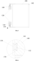
FIG. 4 is a side view of a shelf assembly according to an embodiment of the present invention; -
FIG. 5 is a sectional view ofFIG. 4 at A-A; -
FIG. 6 is an enlargement view ofFIG. 5 at B; -
FIG. 7 is an enlargement view ofFIG. 3 at C; -
FIG. 8 is a structural diagram of a connecting plate according to an embodiment of the present invention; and -
FIG. 9 is a perspective view of a storage cabinet according to an embodiment of the present invention. - Reference numerals:
- 100: shelf; 101: up button; 102: down button; 103: first inserting plate;
- 1031: limiting portion; 104: second inserting plate; 110: mounting rod; 120: movement component;
- 130: guide rod; 131: mounting hole; 132: bulge; 140: sliding block; 141: sliding groove;
- 150: mounting seat; 160: connecting plate; 161: top plate; 1611: avoidance gap;
- 162: side plate; 1621: first inserting hole; 1622: second inserting hole; 170: rolling ball;
- 180: cabinet body.
- Referring to
FIG. 1 to FIG. 8 , an embodiment of the present invention provides a shelf assembly, including amounting rod 110, a plurality ofshelves 100,movement components 120 corresponding to theshelves 100 and driving components corresponding to themovement components 120. A peripheral wall of themounting rod 110 is formed with an external thread along an axis direction. Each of themovement components 120 is connected to thecorresponding shelf 110, and formed with an internal thread hole matching the external thread of the mountingrod 110. The driving component is connected to themovement component 120 and configured to drive themovement component 120 to rotate. - The driving component directly drives the
corresponding movement component 120 to rotate since the mountingrod 110 is fixed in the shelf assembly. Themovement component 120 can transform its own rotational motion into linear motion by continuously matching with the external thread of the mountingrod 110 in the process of rotation, thereby driving theshelf 100 connected to it to move along the axial direction of the mountingrod 110. Therefore, the shelf assembly in the present invention can realize independent adjustment of the plurality ofshelves 100 merely by arranging a set of mountingrods 110. In other words, all theshelves 100 can share the same set of mountingrods 110, thus it is only needed to control the corresponding driving component to drive themovement component 120 to rotate when adjusting the height of theshelves 100. Therefore, the present application not only saves the cost, but also facilitates mounting, and provides good-looking and concise appearance. In addition, since the mountingrods 110 and themovement component 120 are connected through thread, either in the process of adjusting the height of theshelves 100 or when theshelves 100 are fixed, theshelves 100 will not slide down along the mountingrods 110 because of the load bearing under the joint constraint of the external threads of the mountingrods 110 and the internal threads of themovement components 120. - As shown in
FIG.3 , the shelf assembly further includes aguide rod 130 and slidingblocks 140. Theguide rod 130 is arranged in parallel with the mountingrod 110, where theguide rod 130 is formed with a first connecting portion along its height direction; one side of theslide bock 140 is formed with a second connecting portion slidably matched with the first connecting portion, and the other side of the slidingblock 140 is connected with theshelf 100. It can be seen from the above that themovement components 120, the slidingblocks 140 and theshelves 100 move synchronously. When themovement components 120 move, the slidingblocks 140 and theshelves 100 also move together with them. - It should be noted that there are many modes to realize sliding connection between the
guide rod 130 and the slidingblock 140, for example: - mode 1: the first connecting portion is a
bulge 132 formed on a surface of theguide rod 130, and the second connecting portion is a slidinggroove 141 formed on a surface of the slidingblock 140; and - mode 2: the first connecting portion is a sliding groove formed on the surface of the guide rod, and the second connecting portion is a bulge formed on the surface of the sliding block.
- In order to prevent the
bulge 132 from separating from the slidinggroove 141 during the sliding process of the slidingblock 140, the slidinggroove 141 can be a swallowtail groove, at which point thebulge 132 is a swallowtail structure matching the swallowtail groove. In addition, in order to reduce the resistance in the sliding process of the slidingblock 140, an inner wall of the slidinggroove 141 or an outer wall of thebulge 132 is embedded with a plurality of rollingballs 170. In other words, the inner wall of the slidinggroove 141 or the outer wall of thebulge 132 is provided with dimples corresponding to the rollingballs 170 one-to-one, and one part of the rollingball 170 is embedded in the dimple, and the other part of the rollingball 170 protrudes out of the dimple. Therefore, during the sliding process of the slidingblock 140, the rollingballs 170 continuously rotate under the action of friction. - In addition, in order to facilitate installation, the
movement component 120 and the slidingblock 140 are both connected to a connectingplate 160. Where the connectingplate 160 can be welded on theshelf 100, or detachably connected to theshelf 100. For example, as shown inFIG. 3 , the connectingplate 160 includes atop plate 161 and aside plate 162, and a top of theside plate 162 is connected to a side wall of thetop plate 162; thetop plate 161 is connected to a top surface of themovement component 120, theside plate 162 is connected to a side wall of the slidingblock 140, and theside plate 162 is detachably connected to theshelf 100. - Specifically, as shown in
FIG. 7 to FIG. 8 , theshelf 100 is provided with a first insertingplate 103 and a second insertingplate 104, theside plate 162 is provided with a first insertinghole 1621 for socketing the first insertingplate 103 and a second insertinghole 1622 for socketing the second insertingplate 104, an end of the first insertingplate 103 distal to theshelf 100 is formed with a limitingportion 1031 extending downward, and the limitingportion 1031 is hooked on theside plate 162. - The
top plate 161 can be connected to the top surface of themovement component 120 through screws, that is, thetop plate 161 can be provided with a plurality of first through holes, and the top of themovement component 120 can be provided with first thread holes corresponding to the first through holes. Theside plate 162 can also be connected to the side wall of the slidingblock 140 through screws, that is, theside plate 162 can be provided with a plurality of second through holes, and the top surface of the slidingblock 140 can be provided with second thread holes corresponding to the second through holes. - Further, the
top plate 161 is provided with anavoidance gap 1611 corresponding to the mountingrod 110, so that the mountingrod 110 passes through thetop plate 161 through theavoidance gap 1611 when thetop plate 161 is mounted on the top of themovement component 120. - The driving component can be automatic or manual. Specifically, it is as follows.
- 1. automatic. At this time, the driving component is an electric device. For example, as shown in
FIG. 3 , the driving component and themovement component 120 constitute a screw stepping motor. It should be noted that since the screw stepping motor belongs to the prior art, its specific structure and working principle will not be described here. - Further, in order to facilitate the user's operation, the
shelf 100 is provided with control buttons electrically connected to the driving component. For example, the control buttons include an upbutton 101 and adown button 102. Therefore, the user only needs to press the upbutton 101 when theshelf 100 needs to be raised, and the driving component will drive theshelf 100 to move up by a specified distance along the mountingrod 110 every time the upbutton 101 is pressed. Similarly, the user only needs to press thedown button 102 when theshelf 100 needs to be lowered. The driving component will drive theshelf 100 to move down by a specified distance along the mountingrod 110 every time thedown button 102 is pressed. By providing control buttons on theshelves 100, the shelf assembly according to the embodiment of the present application not only facilitates a user to control the movement of theshelves 100, but also enable the user to adjust without diverting their sight during the whole process compared with the control buttons provided on other components. That is, the user does not need to quickly divert their sight to observe the movement of theshelves 100 after operating the control button. - In addition, in order to ensure the accuracy of adjustment, the specified distance of the driving component moving along the mounting
rod 110 is usually very small every time the upbutton 101 or thedown button 102 is pressed, thus the user needs to press the upbutton 101 or thedown button 102 multiple times when theshelf 100 needs to move a large distance. Therefore, in order to improve the user experience and reduce the times of pressing theup button 101 or thedown button 102, the control button further includes a setting button, which is electrically connected to the driving component, and the side wall of theshelf 100 is further provided with a display screen electrically connected to the setting button at this time, where the setting button is configured to set the specified distance of the driving component moving along the mountingrod 110 when the upbutton 101 or thedown button 102 is pressed; the display screen is configured to display the specified distance. Therefore, the user can set the specified distance for a single movement of the driving component according to the distance thatshelf 100 needs to move. In order to facilitate the user's operation, the control button can also be provided on the front side of theshelf 100, where the "front side" of theshelf 100 is based on the mounting direction of theshelf 100, and the side of theshelf 100 facing the cabinet door is the front side, and the side facing away the cabinet door is the rear side after theshelves 100 is mounted in acabinet body 180. - 2. manual. At this time, the moving
component 120 includes a housing and a rotating component provided in the housing, the driving component includes a handle and a conical gear provided in the housing; the housing is provided thereon with a through hole extending through the longitudinal direction, the rotating component is rotatably provided in the through hole by a bearing, the rotating component is provided thereon with an internal thread hole through the longitudinal direction, the outer wall of the rotating component is provided with a tooth groove meshed with the conical gear, and an end of the handle is inserted into the housing to connect with a rotating shaft of the conical gear. Therefore, the user only needs to rotate the handle clockwise when theshelf 100 needs to be raised. Since the handle is connected to the rotating shaft of the conical gear, and the conical gear is meshed with the groove of the rotating component, the handle, the conical gear and the rotating component move synchronously. Therefore, when the user rotates the handle, the conical gear rotates together with it, thereby driving the rotating component to rotate simultaneously. Since the rotating component matches with the thread of the mountingrod 110 through its internal thread hole, during the rotation process of the rotating component, as the internal thread of the rotating component constantly matches with the external thread of the mountingrods 110 located above theshelves 100, the rotational motion of the rotating component is transformed into a linear motion, that is, the rotating component drives theshelves 100 to move upwards through the housing at this time. Conversely, the user only needs to rotate the handle counterclockwise when theshelves 100 needs to be lowered. It should be noted that, the direction of themovement component 120 moving along the mountingrod 110 when rotating the handle clockwise or counterclockwise can be set by setting the rotating direction of the external thread on the mountingrod 110. - Referring to
FIG. 9 , an embodiment of the present invention further provides a storage cabinet, which includes acabinet body 180 and the shelf assembly mentioned above, and the shelf assembly is provided in thecabinet body 180. Where the storage cabinet can be, but not limited to, a refrigerator or a retail cabinet. The structure and principle of the shelf assembly in this embodiment are the same as those in the above embodiments, and will not be described in detail in this embodiment. - The shelf assembly in the present invention can realize independent adjustment of the plurality of
shelves 100 only by using a set of mountingrods 110, which not only saves the cost, but also facilitates mounting, and provides good-looking and concise appearance. In addition, either in the process of adjusting the height of theshelves 100 or when theshelves 100 are fixed, theshelves 100 will not slide down along the mountingrods 110 because of load bearing under the joint constraint of the external threads of the mountingrods 110 and the internal threads of themovement components 120, which ensures the load-bearing demand of the shelves. - Taking a refrigerator as an example, the back plate of the refrigerator is provided with two parallel mounting
rods 110, each mountingrod 110 is equipped with aguide rod 130, the end of the mountingrod 110 and the end of thecorresponding guide rod 130 are fixed on the back plate of the refrigerator through a mountingseat 150, themovement components 120 and the slidingblocks 140 are connected to back sides of the correspondingshelves 100 through the connectingplates 160. In order to improve the stability of theguide rod 130, theguide rod 130 is provided with a plurality of mountingholes 131 at intervals along the height direction thereof, and the back plate of the refrigerator is provided with thread holes corresponding to the mountingholes 131 one-to-one. Therefore, during installation, theguide rod 130 and the mountingrod 110 can be fixed on the back plate of the refrigerator through the mountingseat 150 first, and then screws are screwed into theguide rod 130. Specifically, one end of each screw is passed through the mountinghole 131 and screwed into the corresponding thread hole, so that theguide rod 130 can be firmly fixed on the inner wall of the refrigerator to prevent it from being skewed during use. - The mounting
rod 110 and theguide rod 130 can also be fixed on the left and right sides of the inner wall of the refrigerator in addition to being fixed on the back plate of the refrigerator. Besides, the number of mountingrod 110 and guiderod 130 can be two or more.
Claims (12)
- A shelf assembly, comprising:a plurality of shelves (100);a mounting rod (110), a peripheral wall of which is formed with an external thread along an axis direction;movement components (120) corresponding to the shelves (100), wherein each of the movement components (120) is connected to a corresponding shelf (100) and formed with an internal thread hole matching the external thread of the mounting rod (110);driving components corresponding to the movement components (120), wherein each of the driving components is connected to the movement component (120) and configured to drive the movement component (120) to rotate;a guide rod (130), provided in parallel with the mounting rod (110), wherein the guide rod (130) is formed with a first connecting portion along a height direction;sliding blocks (140), wherein one side of each sliding block (140) is formed with a second connecting portion slidably matched with the first connecting portion, and another side of each sliding block (140) is connected with the shelf (100);characterised in thata movement component (120) from among the movement components (120) and a sliding block (140) from among the sliding blocks (140) are both connected to a connecting plate (160), and the connecting plate (160) is detachably connected to the shelf (100).
- The shelf assembly according to claim 1, wherein the first connecting portion is a bulge (132) formed on a surface of the guide rod (130), and the second connecting portion is a sliding groove (141) formed on a surface of the sliding block (140); or, the first connecting portion is a sliding groove (141) formed on the surface of the guide rod (130), and the second connecting portion is a bulge (132) formed on the surface of the sliding block (140).
- The shelf assembly according to claim 2, wherein the sliding groove (141) is a swallowtail groove.
- The shelf assembly according to claim 2, wherein an inner wall of the sliding groove (141) or an outer wall of the bulge (132) is embedded with a plurality of rolling balls (170).
- The shelf assembly according to claim 1, wherein the connecting plate (160) comprises a top plate (161) and a side plate (162), and a top of the side plate (162) is connected to a side wall of the top plate (161); the top plate (161) is connected to a top surface of a movement component (120) from among the movement components (120), the side plate (162) is connected to a side wall of the sliding block (140), and the side plate (162) is detachably connected to the shelf (100).
- The shelf assembly according to claim 5, wherein the shelf (100) is provided with a first inserting plate (103) and a second inserting plate (104) , the side plate (162) is provided with a first inserting hole (1621) for socketing the first inserting plate (103) and a second inserting hole (1622) for socketing the second inserting plate (104), an end of the first inserting plate (103) distal to the shelf (100) is formed with a limiting portion (1031) extending downward, and the limiting portion (1031) is hooked on the side plate (162).
- The shelf assembly according to any one of claims 1 to 6, wherein the movement components (120) and the driving components constitute a screw stepping motor.
- The shelf assembly according to any one of claims 1 to 6, wherein the shelf (100) is provided with control buttons electrically connected to the driving components.
- The shelf assembly according to any one of claims 1 to 6, wherein the movement component (120) from among the movement components (120) comprises a housing and a rotating component provided in the housing, the housing is formed thereon with a through hole extending through a longitudinal direction, the rotating component is rotatably provided in the through hole by a bearing, the rotating component is formed thereon with an internal thread hole extending through the longitudinal direction, and a driving component from among the driving components is configured to drive the rotating component to rotate.
- The shelf assembly according to claim 9, wherein the driving component from among the driving components comprises a handle and a conical gear provided in the housing, an outer wall of the rotating component is provided with a tooth groove meshed with the conical gear, and an end of the handle is inserted into the housing to connect with a rotating shaft of the conical gear.
- A storage cabinet, comprising a cabinet body (180) and the shelf assembly according to any one of claims 1 to 10, wherein the shelf assembly is provided in the cabinet body.
- The storage cabinet according to claim 11, wherein the storage cabinet (180) is a refrigerator or a retail cabinet.
Applications Claiming Priority (2)
| Application Number | Priority Date | Filing Date | Title |
|---|---|---|---|
| CN202010065228.4A CN111174524B (en) | 2020-01-20 | 2020-01-20 | Shelving Components and Storage Cabinets |
| PCT/CN2020/129752 WO2021147495A1 (en) | 2020-01-20 | 2020-11-18 | Shelf assembly and storage cabinet |
Publications (3)
| Publication Number | Publication Date |
|---|---|
| EP4095467A1 EP4095467A1 (en) | 2022-11-30 |
| EP4095467A4 EP4095467A4 (en) | 2024-01-17 |
| EP4095467B1 true EP4095467B1 (en) | 2025-03-12 |
Family
ID=70651241
Family Applications (1)
| Application Number | Title | Priority Date | Filing Date |
|---|---|---|---|
| EP20916082.9A Active EP4095467B1 (en) | 2020-01-20 | 2020-11-18 | Shelf assembly and storage cabinet |
Country Status (5)
| Country | Link |
|---|---|
| US (1) | US12171331B2 (en) |
| EP (1) | EP4095467B1 (en) |
| KR (1) | KR102882377B1 (en) |
| CN (1) | CN111174524B (en) |
| WO (1) | WO2021147495A1 (en) |
Families Citing this family (7)
| Publication number | Priority date | Publication date | Assignee | Title |
|---|---|---|---|---|
| CN111174524B (en) * | 2020-01-20 | 2021-08-31 | 合肥华凌股份有限公司 | Shelving Components and Storage Cabinets |
| CN111578575A (en) * | 2020-05-20 | 2020-08-25 | 长虹美菱股份有限公司 | Lifting device for refrigerator partition frame |
| CN113995242B (en) * | 2021-11-12 | 2023-10-27 | 江西讯森智能科技有限公司 | An intelligent automatic layer selection cabinet for confidential files |
| USD1129942S1 (en) * | 2022-04-11 | 2026-06-16 | Icf S.P.A. | Storage assembly |
| CN115213864B (en) * | 2022-07-10 | 2024-11-01 | 广州盈福精密科技有限公司 | Workbench convenient to adjust for numerical control machine tool |
| CN116534477A (en) * | 2023-04-06 | 2023-08-04 | 埃驰汽车零部件(天津)有限公司 | High-level goods shelf and use method |
| CN116481254B (en) * | 2023-04-23 | 2025-09-26 | 长虹美菱股份有限公司 | Refrigerator shelf lifting device and refrigerator |
Citations (1)
| Publication number | Priority date | Publication date | Assignee | Title |
|---|---|---|---|---|
| CN209931908U (en) * | 2019-03-08 | 2020-01-14 | 西安阿尔斯通永济电气设备有限公司 | Goods shelf with interlayer lifting device |
Family Cites Families (37)
| Publication number | Priority date | Publication date | Assignee | Title |
|---|---|---|---|---|
| US1969957A (en) * | 1930-05-03 | 1934-08-14 | Frank M Zimmerman | Shelving |
| GB1099351A (en) * | 1964-03-24 | 1968-01-17 | Southborough Group Ltd | Improvements in or relating to extension slides for drawers or the like |
| JPH07298963A (en) * | 1994-05-10 | 1995-11-14 | Fuji Electric Co Ltd | Showcase product display shelves |
| KR0122001Y1 (en) * | 1995-04-20 | 1998-08-17 | 김광호 | Shelf lift of refrigerator |
| KR19990074425A (en) * | 1998-03-11 | 1999-10-05 | 윤종용 | Rack lift of refrigerator |
| CN2356562Y (en) * | 1998-12-09 | 2000-01-05 | 卓家良 | Automatic lifting corner cabinet |
| JP4111038B2 (en) * | 2000-03-27 | 2008-07-02 | 三菱電機株式会社 | refrigerator |
| JP3648138B2 (en) * | 2000-03-27 | 2005-05-18 | 三菱電機株式会社 | refrigerator |
| JP2004173959A (en) | 2002-11-27 | 2004-06-24 | Sun Wave Ind Co Ltd | Article storage shelf |
| US7306303B2 (en) * | 2003-06-30 | 2007-12-11 | General Electric Company | Methods and apparatus for refrigerator compartment |
| DE102005043356A1 (en) * | 2005-09-12 | 2007-03-15 | BSH Bosch und Siemens Hausgeräte GmbH | Refrigeration unit with height-adjustable refrigerated goods carrier with safety shutdown |
| DE102005057148A1 (en) * | 2005-11-30 | 2007-06-06 | BSH Bosch und Siemens Hausgeräte GmbH | Kitchen appliance with height-adjustable shelf |
| JP4853131B2 (en) * | 2005-12-19 | 2012-01-11 | 富士電機株式会社 | Showcase |
| WO2008062991A1 (en) * | 2006-11-20 | 2008-05-29 | Lg Electronics Inc. | Height adjusting apparatus of shelf for refrigerator |
| KR101573532B1 (en) * | 2008-12-08 | 2015-12-01 | 엘지전자 주식회사 | Height adjusters for refrigerators and refrigerators |
| US8267493B2 (en) * | 2009-01-15 | 2012-09-18 | Lg Electronics Inc. | Refrigerator |
| KR20100085252A (en) * | 2009-01-20 | 2010-07-29 | 주식회사 대우일렉트로닉스 | Height adjustment device for refrigerator shelf |
| DE102009000845A1 (en) * | 2009-02-13 | 2010-08-19 | BSH Bosch und Siemens Hausgeräte GmbH | Refrigeration unit with height-adjustable refrigerated goods storage |
| KR101704810B1 (en) * | 2009-05-06 | 2017-02-08 | 엘지전자 주식회사 | Refrigerator whit height adjustable shelf and control method thereof |
| ES2525321T3 (en) * | 2009-12-30 | 2014-12-22 | Arçelik Anonim Sirketi | Cooling device |
| CN206056105U (en) | 2016-08-26 | 2017-03-29 | 青岛海尔股份有限公司 | A kind of height-adjustable shelf assembly and the refrigerator with which |
| CN106168431B (en) | 2016-08-26 | 2018-12-14 | 青岛海尔股份有限公司 | A kind of height-adjustable shelf assembly and the refrigerator with it |
| CN106568291A (en) * | 2016-11-10 | 2017-04-19 | 青岛海尔股份有限公司 | Lifting synchronization system of refrigerator rack |
| KR101878436B1 (en) * | 2016-12-22 | 2018-07-13 | 주식회사 한국랙스 | Electric mobile rack |
| CN206600978U (en) * | 2017-02-08 | 2017-10-31 | 青岛海尔股份有限公司 | Rack |
| CN208274396U (en) | 2017-08-25 | 2018-12-25 | 湖北天佑环保设备有限公司 | A kind of instruction case convenient to use |
| US10694843B2 (en) * | 2017-09-12 | 2020-06-30 | Haier Us Appliance Solutions, Inc. | Adjustable shelving assembly for a refrigerator appliance |
| CN108088165A (en) * | 2017-12-06 | 2018-05-29 | 青岛彭大电器有限公司 | A kind of automatic lifting laminated frame device and a kind of refrigerator |
| CN209377079U (en) | 2018-08-02 | 2019-09-13 | 鹤壁市人民医院 | A kind of medical magazine |
| CN108996098B (en) * | 2018-08-23 | 2020-06-02 | 重庆金鼎仓储设备有限公司 | Goods shelf with fixing structure for logistics |
| CN109855379A (en) * | 2019-03-22 | 2019-06-07 | 合肥华凌股份有限公司 | Lifting Shelves and Refrigeration Equipment |
| CN112444042B (en) * | 2019-08-30 | 2024-09-24 | 海信冰箱有限公司 | Refrigerator with lifting shelves |
| US11125491B2 (en) * | 2019-09-23 | 2021-09-21 | Haier Us Appliance Solutions, Inc. | Adjustable shelf assembly for an appliance |
| CN111174524B (en) | 2020-01-20 | 2021-08-31 | 合肥华凌股份有限公司 | Shelving Components and Storage Cabinets |
| CN111351303A (en) * | 2020-03-06 | 2020-06-30 | 合肥华凌股份有限公司 | Shelf lifts and refrigeration equipment for refrigeration equipment |
| CN111664649A (en) * | 2020-06-18 | 2020-09-15 | 长虹美菱股份有限公司 | A refrigerator shelf automatic lifting device |
| CN218279200U (en) * | 2022-05-11 | 2023-01-13 | 南通荣彦物流设备制造有限公司 | Roller goods shelf for logistics distribution center |
-
2020
- 2020-01-20 CN CN202010065228.4A patent/CN111174524B/en active Active
- 2020-11-18 KR KR1020227027715A patent/KR102882377B1/en active Active
- 2020-11-18 EP EP20916082.9A patent/EP4095467B1/en active Active
- 2020-11-18 WO PCT/CN2020/129752 patent/WO2021147495A1/en not_active Ceased
- 2020-11-18 US US17/793,582 patent/US12171331B2/en active Active
Patent Citations (1)
| Publication number | Priority date | Publication date | Assignee | Title |
|---|---|---|---|---|
| CN209931908U (en) * | 2019-03-08 | 2020-01-14 | 西安阿尔斯通永济电气设备有限公司 | Goods shelf with interlayer lifting device |
Also Published As
| Publication number | Publication date |
|---|---|
| KR20220119172A (en) | 2022-08-26 |
| KR102882377B1 (en) | 2025-11-07 |
| CN111174524B (en) | 2021-08-31 |
| US20230047342A1 (en) | 2023-02-16 |
| EP4095467A1 (en) | 2022-11-30 |
| US12171331B2 (en) | 2024-12-24 |
| CN111174524A (en) | 2020-05-19 |
| EP4095467A4 (en) | 2024-01-17 |
| WO2021147495A1 (en) | 2021-07-29 |
Similar Documents
| Publication | Publication Date | Title |
|---|---|---|
| US12171331B2 (en) | Shelf assembly and storage cabinet | |
| US8529001B2 (en) | Refrigerator with height-adjustable shelf for refrigerated goods | |
| KR102100192B1 (en) | Refrigerator | |
| KR102309146B1 (en) | drawer and refrigerator with drawer | |
| KR102867823B1 (en) | Shelving units and storage cabinets | |
| KR20200137353A (en) | An apparatus for moving up and down a shelf and refrigerator including the same | |
| EP4202332A1 (en) | Adjustable shelf device and refrigerator having same | |
| KR200468206Y1 (en) | Refrigerator having shelf assembly | |
| CN209712060U (en) | It is easily assembled the lifting cabinet of cabinet body | |
| JP2026506976A (en) | Translation-rotation fittings and furniture or household appliances | |
| KR20140097798A (en) | Shelf assembly and refrigerator including the same | |
| CN210036017U (en) | Automatic drawer | |
| CN212130247U (en) | Damper hinge | |
| KR19990054661A (en) | Refrigerator | |
| CN224201423U (en) | Adjusting assembly and display device | |
| CN219109104U (en) | Interactive informationized intelligent display cabinet | |
| CN218571783U (en) | Linear motion mechanism, linear motion assembly, drawer assembly and storage cabinet | |
| CN222486850U (en) | A multi-angle display device for industrial robots | |
| CN214760100U (en) | Baffle reinforcing apparatus that audit material filing cabinet used for accounting | |
| JPH0445386A (en) | Shelf device in refrigerator | |
| JPH03175281A (en) | Shelf device of refrigerator | |
| CN117918668A (en) | Display cabinet shelf convenient for tallying and display cabinet | |
| CN112901034A (en) | Solid wood cabinet door capable of being disassembled and assembled and replaced by modules | |
| KR20090011416A (en) | Displacement device for display | |
| JPH03175279A (en) | Shelf device of refrigerator |
Legal Events
| Date | Code | Title | Description |
|---|---|---|---|
| STAA | Information on the status of an ep patent application or granted ep patent |
Free format text: STATUS: THE INTERNATIONAL PUBLICATION HAS BEEN MADE |
|
| PUAI | Public reference made under article 153(3) epc to a published international application that has entered the european phase |
Free format text: ORIGINAL CODE: 0009012 |
|
| STAA | Information on the status of an ep patent application or granted ep patent |
Free format text: STATUS: REQUEST FOR EXAMINATION WAS MADE |
|
| 17P | Request for examination filed |
Effective date: 20220819 |
|
| AK | Designated contracting states |
Kind code of ref document: A1 Designated state(s): AL AT BE BG CH CY CZ DE DK EE ES FI FR GB GR HR HU IE IS IT LI LT LU LV MC MK MT NL NO PL PT RO RS SE SI SK SM TR |
|
| DAV | Request for validation of the european patent (deleted) | ||
| DAX | Request for extension of the european patent (deleted) | ||
| A4 | Supplementary search report drawn up and despatched |
Effective date: 20231219 |
|
| RIC1 | Information provided on ipc code assigned before grant |
Ipc: A47B 57/06 20060101ALI20231213BHEP Ipc: B65G 1/02 20060101ALI20231213BHEP Ipc: A47B 96/02 20060101ALI20231213BHEP Ipc: F25D 11/00 20060101ALI20231213BHEP Ipc: F25D 25/02 20060101AFI20231213BHEP |
|
| GRAP | Despatch of communication of intention to grant a patent |
Free format text: ORIGINAL CODE: EPIDOSNIGR1 |
|
| STAA | Information on the status of an ep patent application or granted ep patent |
Free format text: STATUS: GRANT OF PATENT IS INTENDED |
|
| RIC1 | Information provided on ipc code assigned before grant |
Ipc: A47B 57/06 20060101ALI20240930BHEP Ipc: B65G 1/02 20060101ALI20240930BHEP Ipc: A47B 96/02 20060101ALI20240930BHEP Ipc: F25D 11/00 20060101ALI20240930BHEP Ipc: F25D 25/02 20060101AFI20240930BHEP |
|
| INTG | Intention to grant announced |
Effective date: 20241011 |
|
| GRAS | Grant fee paid |
Free format text: ORIGINAL CODE: EPIDOSNIGR3 |
|
| GRAA | (expected) grant |
Free format text: ORIGINAL CODE: 0009210 |
|
| STAA | Information on the status of an ep patent application or granted ep patent |
Free format text: STATUS: THE PATENT HAS BEEN GRANTED |
|
| AK | Designated contracting states |
Kind code of ref document: B1 Designated state(s): AL AT BE BG CH CY CZ DE DK EE ES FI FR GB GR HR HU IE IS IT LI LT LU LV MC MK MT NL NO PL PT RO RS SE SI SK SM TR |
|
| REG | Reference to a national code |
Ref country code: GB Ref legal event code: FG4D |
|
| REG | Reference to a national code |
Ref country code: CH Ref legal event code: EP |
|
| REG | Reference to a national code |
Ref country code: DE Ref legal event code: R096 Ref document number: 602020047769 Country of ref document: DE |
|
| REG | Reference to a national code |
Ref country code: IE Ref legal event code: FG4D |
|
| PG25 | Lapsed in a contracting state [announced via postgrant information from national office to epo] |
Ref country code: RS Free format text: LAPSE BECAUSE OF FAILURE TO SUBMIT A TRANSLATION OF THE DESCRIPTION OR TO PAY THE FEE WITHIN THE PRESCRIBED TIME-LIMIT Effective date: 20250612 |
|
| PG25 | Lapsed in a contracting state [announced via postgrant information from national office to epo] |
Ref country code: FI Free format text: LAPSE BECAUSE OF FAILURE TO SUBMIT A TRANSLATION OF THE DESCRIPTION OR TO PAY THE FEE WITHIN THE PRESCRIBED TIME-LIMIT Effective date: 20250312 |
|
| PG25 | Lapsed in a contracting state [announced via postgrant information from national office to epo] |
Ref country code: ES Free format text: LAPSE BECAUSE OF FAILURE TO SUBMIT A TRANSLATION OF THE DESCRIPTION OR TO PAY THE FEE WITHIN THE PRESCRIBED TIME-LIMIT Effective date: 20250312 |
|
| REG | Reference to a national code |
Ref country code: LT Ref legal event code: MG9D |
|
| PG25 | Lapsed in a contracting state [announced via postgrant information from national office to epo] |
Ref country code: NO Free format text: LAPSE BECAUSE OF FAILURE TO SUBMIT A TRANSLATION OF THE DESCRIPTION OR TO PAY THE FEE WITHIN THE PRESCRIBED TIME-LIMIT Effective date: 20250612 |
|
| PG25 | Lapsed in a contracting state [announced via postgrant information from national office to epo] |
Ref country code: HR Free format text: LAPSE BECAUSE OF FAILURE TO SUBMIT A TRANSLATION OF THE DESCRIPTION OR TO PAY THE FEE WITHIN THE PRESCRIBED TIME-LIMIT Effective date: 20250312 |
|
| REG | Reference to a national code |
Ref country code: NL Ref legal event code: MP Effective date: 20250312 |
|
| PG25 | Lapsed in a contracting state [announced via postgrant information from national office to epo] |
Ref country code: LV Free format text: LAPSE BECAUSE OF FAILURE TO SUBMIT A TRANSLATION OF THE DESCRIPTION OR TO PAY THE FEE WITHIN THE PRESCRIBED TIME-LIMIT Effective date: 20250312 |
|
| PG25 | Lapsed in a contracting state [announced via postgrant information from national office to epo] |
Ref country code: GR Free format text: LAPSE BECAUSE OF FAILURE TO SUBMIT A TRANSLATION OF THE DESCRIPTION OR TO PAY THE FEE WITHIN THE PRESCRIBED TIME-LIMIT Effective date: 20250613 Ref country code: BG Free format text: LAPSE BECAUSE OF FAILURE TO SUBMIT A TRANSLATION OF THE DESCRIPTION OR TO PAY THE FEE WITHIN THE PRESCRIBED TIME-LIMIT Effective date: 20250312 |
|
| REG | Reference to a national code |
Ref country code: AT Ref legal event code: MK05 Ref document number: 1775301 Country of ref document: AT Kind code of ref document: T Effective date: 20250312 |
|
| PG25 | Lapsed in a contracting state [announced via postgrant information from national office to epo] |
Ref country code: NL Free format text: LAPSE BECAUSE OF FAILURE TO SUBMIT A TRANSLATION OF THE DESCRIPTION OR TO PAY THE FEE WITHIN THE PRESCRIBED TIME-LIMIT Effective date: 20250312 |
|
| PG25 | Lapsed in a contracting state [announced via postgrant information from national office to epo] |
Ref country code: SE Free format text: LAPSE BECAUSE OF FAILURE TO SUBMIT A TRANSLATION OF THE DESCRIPTION OR TO PAY THE FEE WITHIN THE PRESCRIBED TIME-LIMIT Effective date: 20250312 |
|
| PG25 | Lapsed in a contracting state [announced via postgrant information from national office to epo] |
Ref country code: SM Free format text: LAPSE BECAUSE OF FAILURE TO SUBMIT A TRANSLATION OF THE DESCRIPTION OR TO PAY THE FEE WITHIN THE PRESCRIBED TIME-LIMIT Effective date: 20250312 |
|
| PG25 | Lapsed in a contracting state [announced via postgrant information from national office to epo] |
Ref country code: PT Free format text: LAPSE BECAUSE OF FAILURE TO SUBMIT A TRANSLATION OF THE DESCRIPTION OR TO PAY THE FEE WITHIN THE PRESCRIBED TIME-LIMIT Effective date: 20250714 |
|
| PG25 | Lapsed in a contracting state [announced via postgrant information from national office to epo] |
Ref country code: PL Free format text: LAPSE BECAUSE OF FAILURE TO SUBMIT A TRANSLATION OF THE DESCRIPTION OR TO PAY THE FEE WITHIN THE PRESCRIBED TIME-LIMIT Effective date: 20250312 Ref country code: IT Free format text: LAPSE BECAUSE OF FAILURE TO SUBMIT A TRANSLATION OF THE DESCRIPTION OR TO PAY THE FEE WITHIN THE PRESCRIBED TIME-LIMIT Effective date: 20250312 |
|
| PG25 | Lapsed in a contracting state [announced via postgrant information from national office to epo] |
Ref country code: AT Free format text: LAPSE BECAUSE OF FAILURE TO SUBMIT A TRANSLATION OF THE DESCRIPTION OR TO PAY THE FEE WITHIN THE PRESCRIBED TIME-LIMIT Effective date: 20250312 |
|
| PG25 | Lapsed in a contracting state [announced via postgrant information from national office to epo] |
Ref country code: EE Free format text: LAPSE BECAUSE OF FAILURE TO SUBMIT A TRANSLATION OF THE DESCRIPTION OR TO PAY THE FEE WITHIN THE PRESCRIBED TIME-LIMIT Effective date: 20250312 Ref country code: CZ Free format text: LAPSE BECAUSE OF FAILURE TO SUBMIT A TRANSLATION OF THE DESCRIPTION OR TO PAY THE FEE WITHIN THE PRESCRIBED TIME-LIMIT Effective date: 20250312 |
|
| PG25 | Lapsed in a contracting state [announced via postgrant information from national office to epo] |
Ref country code: RO Free format text: LAPSE BECAUSE OF FAILURE TO SUBMIT A TRANSLATION OF THE DESCRIPTION OR TO PAY THE FEE WITHIN THE PRESCRIBED TIME-LIMIT Effective date: 20250312 |
|
| PG25 | Lapsed in a contracting state [announced via postgrant information from national office to epo] |
Ref country code: SK Free format text: LAPSE BECAUSE OF FAILURE TO SUBMIT A TRANSLATION OF THE DESCRIPTION OR TO PAY THE FEE WITHIN THE PRESCRIBED TIME-LIMIT Effective date: 20250312 |
|
| PG25 | Lapsed in a contracting state [announced via postgrant information from national office to epo] |
Ref country code: IS Free format text: LAPSE BECAUSE OF FAILURE TO SUBMIT A TRANSLATION OF THE DESCRIPTION OR TO PAY THE FEE WITHIN THE PRESCRIBED TIME-LIMIT Effective date: 20250712 |
|
| REG | Reference to a national code |
Ref country code: DE Ref legal event code: R097 Ref document number: 602020047769 Country of ref document: DE |
|
| PGFP | Annual fee paid to national office [announced via postgrant information from national office to epo] |
Ref country code: DE Payment date: 20251124 Year of fee payment: 6 |
|
| PGFP | Annual fee paid to national office [announced via postgrant information from national office to epo] |
Ref country code: GB Payment date: 20251126 Year of fee payment: 6 |
|
| PG25 | Lapsed in a contracting state [announced via postgrant information from national office to epo] |
Ref country code: DK Free format text: LAPSE BECAUSE OF FAILURE TO SUBMIT A TRANSLATION OF THE DESCRIPTION OR TO PAY THE FEE WITHIN THE PRESCRIBED TIME-LIMIT Effective date: 20250312 |
|
| PGFP | Annual fee paid to national office [announced via postgrant information from national office to epo] |
Ref country code: FR Payment date: 20251126 Year of fee payment: 6 |
|
| PLBE | No opposition filed within time limit |
Free format text: ORIGINAL CODE: 0009261 |
|
| STAA | Information on the status of an ep patent application or granted ep patent |
Free format text: STATUS: NO OPPOSITION FILED WITHIN TIME LIMIT |
|
| REG | Reference to a national code |
Ref country code: CH Ref legal event code: L10 Free format text: ST27 STATUS EVENT CODE: U-0-0-L10-L00 (AS PROVIDED BY THE NATIONAL OFFICE) Effective date: 20260121 |
|
| 26N | No opposition filed |
Effective date: 20251215 |
|
| REG | Reference to a national code |
Ref country code: CH Ref legal event code: H13 Free format text: ST27 STATUS EVENT CODE: U-0-0-H10-H13 (AS PROVIDED BY THE NATIONAL OFFICE) Effective date: 20260623 |
|
| PG25 | Lapsed in a contracting state [announced via postgrant information from national office to epo] |
Ref country code: LT Free format text: LAPSE BECAUSE OF FAILURE TO SUBMIT A TRANSLATION OF THE DESCRIPTION OR TO PAY THE FEE WITHIN THE PRESCRIBED TIME-LIMIT Effective date: 20250312 |
|
| PG25 | Lapsed in a contracting state [announced via postgrant information from national office to epo] |
Ref country code: MC Free format text: LAPSE BECAUSE OF FAILURE TO SUBMIT A TRANSLATION OF THE DESCRIPTION OR TO PAY THE FEE WITHIN THE PRESCRIBED TIME-LIMIT Effective date: 20250312 |
|
| PG25 | Lapsed in a contracting state [announced via postgrant information from national office to epo] |
Ref country code: CH Free format text: LAPSE BECAUSE OF NON-PAYMENT OF DUE FEES Effective date: 20251130 Ref country code: LU Free format text: LAPSE BECAUSE OF NON-PAYMENT OF DUE FEES Effective date: 20251118 |