EP4095449B1 - Ein verfahren, system und computerprogrammprodukt zur steuerung einer hlk-anlage - Google Patents
Ein verfahren, system und computerprogrammprodukt zur steuerung einer hlk-anlage Download PDFInfo
- Publication number
- EP4095449B1 EP4095449B1 EP22200387.3A EP22200387A EP4095449B1 EP 4095449 B1 EP4095449 B1 EP 4095449B1 EP 22200387 A EP22200387 A EP 22200387A EP 4095449 B1 EP4095449 B1 EP 4095449B1
- Authority
- EP
- European Patent Office
- Prior art keywords
- zone
- maxres
- zones
- fluid
- network
- Prior art date
- Legal status (The legal status is an assumption and is not a legal conclusion. Google has not performed a legal analysis and makes no representation as to the accuracy of the status listed.)
- Active
Links
Images


Classifications
-
- F—MECHANICAL ENGINEERING; LIGHTING; HEATING; WEAPONS; BLASTING
- F24—HEATING; RANGES; VENTILATING
- F24F—AIR-CONDITIONING; AIR-HUMIDIFICATION; VENTILATION; USE OF AIR CURRENTS FOR SCREENING
- F24F11/00—Control or safety arrangements
- F24F11/70—Control systems characterised by their outputs; Constructional details thereof
- F24F11/72—Control systems characterised by their outputs; Constructional details thereof for controlling the supply of treated air, e.g. its pressure
- F24F11/74—Control systems characterised by their outputs; Constructional details thereof for controlling the supply of treated air, e.g. its pressure for controlling air flow rate or air velocity
- F24F11/75—Control systems characterised by their outputs; Constructional details thereof for controlling the supply of treated air, e.g. its pressure for controlling air flow rate or air velocity for maintaining constant air flow rate or air velocity
-
- F—MECHANICAL ENGINEERING; LIGHTING; HEATING; WEAPONS; BLASTING
- F24—HEATING; RANGES; VENTILATING
- F24F—AIR-CONDITIONING; AIR-HUMIDIFICATION; VENTILATION; USE OF AIR CURRENTS FOR SCREENING
- F24F3/00—Air-conditioning systems in which conditioned primary air is supplied from one or more central stations to distributing units in the rooms or spaces where it may receive secondary treatment; Apparatus specially designed for such systems
- F24F3/06—Air-conditioning systems in which conditioned primary air is supplied from one or more central stations to distributing units in the rooms or spaces where it may receive secondary treatment; Apparatus specially designed for such systems characterised by the arrangements for the supply of heat-exchange fluid for the subsequent treatment of primary air in the room units
-
- F—MECHANICAL ENGINEERING; LIGHTING; HEATING; WEAPONS; BLASTING
- F24—HEATING; RANGES; VENTILATING
- F24D—DOMESTIC- OR SPACE-HEATING SYSTEMS, e.g. CENTRAL HEATING SYSTEMS; DOMESTIC HOT-WATER SUPPLY SYSTEMS; ELEMENTS OR COMPONENTS THEREFOR
- F24D19/00—Details
- F24D19/10—Arrangement or mounting of control or safety devices
- F24D19/1006—Arrangement or mounting of control or safety devices for water heating systems
- F24D19/1009—Arrangement or mounting of control or safety devices for water heating systems for central heating
- F24D19/1015—Arrangement or mounting of control or safety devices for water heating systems for central heating using a valve or valves
- F24D19/1036—Having differential pressure measurement facilities
-
- F—MECHANICAL ENGINEERING; LIGHTING; HEATING; WEAPONS; BLASTING
- F24—HEATING; RANGES; VENTILATING
- F24F—AIR-CONDITIONING; AIR-HUMIDIFICATION; VENTILATION; USE OF AIR CURRENTS FOR SCREENING
- F24F11/00—Control or safety arrangements
- F24F11/30—Control or safety arrangements for purposes related to the operation of the system, e.g. for safety or monitoring
- F24F11/49—Control or safety arrangements for purposes related to the operation of the system, e.g. for safety or monitoring ensuring correct operation, e.g. by trial operation or configuration checks
-
- F—MECHANICAL ENGINEERING; LIGHTING; HEATING; WEAPONS; BLASTING
- F24—HEATING; RANGES; VENTILATING
- F24F—AIR-CONDITIONING; AIR-HUMIDIFICATION; VENTILATION; USE OF AIR CURRENTS FOR SCREENING
- F24F11/00—Control or safety arrangements
- F24F11/50—Control or safety arrangements characterised by user interfaces or communication
- F24F11/54—Control or safety arrangements characterised by user interfaces or communication using one central controller connected to several sub-controllers
-
- F—MECHANICAL ENGINEERING; LIGHTING; HEATING; WEAPONS; BLASTING
- F24—HEATING; RANGES; VENTILATING
- F24F—AIR-CONDITIONING; AIR-HUMIDIFICATION; VENTILATION; USE OF AIR CURRENTS FOR SCREENING
- F24F11/00—Control or safety arrangements
- F24F11/62—Control or safety arrangements characterised by the type of control or by internal processing, e.g. using fuzzy logic, adaptive control or estimation of values
- F24F11/63—Electronic processing
- F24F11/64—Electronic processing using pre-stored data
-
- F—MECHANICAL ENGINEERING; LIGHTING; HEATING; WEAPONS; BLASTING
- F24—HEATING; RANGES; VENTILATING
- F24F—AIR-CONDITIONING; AIR-HUMIDIFICATION; VENTILATION; USE OF AIR CURRENTS FOR SCREENING
- F24F11/00—Control or safety arrangements
- F24F11/70—Control systems characterised by their outputs; Constructional details thereof
- F24F11/80—Control systems characterised by their outputs; Constructional details thereof for controlling the temperature of the supplied air
- F24F11/83—Control systems characterised by their outputs; Constructional details thereof for controlling the temperature of the supplied air by controlling the supply of heat-exchange fluids to heat-exchangers
- F24F11/84—Control systems characterised by their outputs; Constructional details thereof for controlling the temperature of the supplied air by controlling the supply of heat-exchange fluids to heat-exchangers using valves
-
- F—MECHANICAL ENGINEERING; LIGHTING; HEATING; WEAPONS; BLASTING
- F24—HEATING; RANGES; VENTILATING
- F24F—AIR-CONDITIONING; AIR-HUMIDIFICATION; VENTILATION; USE OF AIR CURRENTS FOR SCREENING
- F24F11/00—Control or safety arrangements
- F24F11/89—Arrangement or mounting of control or safety devices
-
- F—MECHANICAL ENGINEERING; LIGHTING; HEATING; WEAPONS; BLASTING
- F24—HEATING; RANGES; VENTILATING
- F24F—AIR-CONDITIONING; AIR-HUMIDIFICATION; VENTILATION; USE OF AIR CURRENTS FOR SCREENING
- F24F5/00—Air-conditioning systems or apparatus not covered by F24F1/00 or F24F3/00, e.g. using solar heat or combined with household units such as an oven or water heater
- F24F5/0003—Exclusively-fluid systems
-
- F—MECHANICAL ENGINEERING; LIGHTING; HEATING; WEAPONS; BLASTING
- F24—HEATING; RANGES; VENTILATING
- F24D—DOMESTIC- OR SPACE-HEATING SYSTEMS, e.g. CENTRAL HEATING SYSTEMS; DOMESTIC HOT-WATER SUPPLY SYSTEMS; ELEMENTS OR COMPONENTS THEREFOR
- F24D2220/00—Components of central heating installations excluding heat sources
- F24D2220/02—Fluid distribution means
- F24D2220/0264—Hydraulic balancing valves
-
- F—MECHANICAL ENGINEERING; LIGHTING; HEATING; WEAPONS; BLASTING
- F24—HEATING; RANGES; VENTILATING
- F24F—AIR-CONDITIONING; AIR-HUMIDIFICATION; VENTILATION; USE OF AIR CURRENTS FOR SCREENING
- F24F2110/00—Control inputs relating to air properties
- F24F2110/40—Pressure, e.g. wind pressure
-
- F—MECHANICAL ENGINEERING; LIGHTING; HEATING; WEAPONS; BLASTING
- F24—HEATING; RANGES; VENTILATING
- F24F—AIR-CONDITIONING; AIR-HUMIDIFICATION; VENTILATION; USE OF AIR CURRENTS FOR SCREENING
- F24F2140/00—Control inputs relating to system states
- F24F2140/10—Pressure
- F24F2140/12—Heat-exchange fluid pressure
-
- F—MECHANICAL ENGINEERING; LIGHTING; HEATING; WEAPONS; BLASTING
- F24—HEATING; RANGES; VENTILATING
- F24F—AIR-CONDITIONING; AIR-HUMIDIFICATION; VENTILATION; USE OF AIR CURRENTS FOR SCREENING
- F24F2221/00—Details or features not otherwise provided for
- F24F2221/50—HVAC for high buildings, e.g. thermal or pressure differences
Definitions
- the present invention relates to a method of controlling a Heating, Ventilating and Air Conditioning HVAC system comprising a fluid transportation network having one or more network sections, each comprising a plurality of parallel zones accommodating a thermal energy exchanger.
- the present invention further relates to a Heating, Ventilating and Air Conditioning HVAC system comprising a fluid transportation network having one or more network sections, each comprising a plurality of parallel zones accommodating a thermal energy exchanger.
- the present invention further relates to a computer program product for a controller of an HVAC system.
- HVAC systems typically comprise a fluid transportation network comprising thermal energy exchanger(s) arranged such as to be able to transfer thermal energy to / extract thermal energy from the environment to be controlled (referred to hereafter as controlled environment) by means of a fluid circulating in said fluid transportation network,
- controlled environment thermal energy exchanger(s) arranged such as to be able to transfer thermal energy to / extract thermal energy from the environment to be controlled (referred to hereafter as controlled environment) by means of a fluid circulating in said fluid transportation network
- the energy exchange or the power transfer is adjusted by regulating the amount of energy delivered to/ extracted from the thermal energy exchanger to heat or cool a room in a building, or by regulating the amount of energy delivered to a chiller for cooling purposes.
- the fluid transport through the fluid transportation circuit of the HVAC system is driven by one or more pumps or fans, the flow is typically regulated by varying the orifice (opening) or position of valves.
- thermal energy exchanger(s) are connected to the fluid transportation network via one or more flow regulating devices such as valves and dampers.
- HVAC actuators are mechanically controlled by HVAC field devices, in particular actuators, including motorized HVAC actuators coupled to the regulating device(s).
- HVAC actuators typically comprise an electric motor, drivingly coupled (through gears and/or other mechanical coupling), to the actuated part, i.e. the regulating device.
- HVAC actuators are electrically controlled by HVAC controllers, in particular an electronic circuit thereof.
- various sensors are used to measure environmental variables such as humidity, temperature, CO 2 or dust particle levels.
- HVAC sensors are used to determine operational parameters of various elements of an HVAC system, such as an actuated position of an actuated part, the operational state of an HVAC actuator.
- Fluid transport networks often comprise one or more network sections, each network section being connected to a fluid transportation circuit through respective supply line(s) and return line(s), each network section comprising a plurality of parallel zones each comprising a consumer, , such as a thermal energy exchanger.
- a consumer such as a thermal energy exchanger.
- the consumers typically have different designs, meaning that they have different geometries of its flow chambers- and have different and/or varying flow volumes and/or throughput.
- the consumers are each configured with a compensation- or balancing organ, for example a flow regulating device, particularly a valve (for liquids) or a damper (for gaseous fluids), which can regulate the flow rate through the respective consumer at different valve/damper opening positions.
- a compensation- or balancing organ for example a flow regulating device, particularly a valve (for liquids) or a damper (for gaseous fluids), which can regulate the flow rate through the respective consumer at different valve/damper opening positions.
- a common requirement to be met for each of the parallel zones within a network section of a fluid transportation network is the fluid pressure being maintained within a specified differential pressure range.
- the specified differential pressure range to be maintained is defined by an operational range of the regulating device(s), the thermal energy consumer and/or any other element within the respective parallel zone, in particular an optimal operational range.
- pressure invariant regulating valves have a specific pressure range within which they are capable of maintaining a specified flowrate irrespective of the fluid pressure.
- the fluid pressure in a parallel zone comprising such a pressure invariant regulating valve is to be maintained within the specific pressure range within which they are capable of maintaining a specified flowrate irrespective of the fluid pressure
- various components of a fluid transportation network have specific operational pressure ranges, or optimal operational pressure ranges, these ranges being determined such as to avoid the turbulences leading to excessive noise and/or wear, such as turbulences due to cavitation of the fluid
- pressure regulating device(s) of a plurality of zones and/or of a network section are controlled based on a differential pressure measured between supply and return line of the network section.
- WO 2014/165497 A1 discloses an air conditioning system comprising a plurality of parallel branches, whereby a first pressure sensor and a second pressure sensor are arranged for measuring the pressure at the branch inlet and the pressure at the branch outlet, respectively, a controller being configured to control a pump such as to regulate a pressure differential (between the pressures as measured by the first pressure sensor and the second pressure sensor).
- a controller being configured to control a pump such as to regulate a pressure differential (between the pressures as measured by the first pressure sensor and the second pressure sensor).
- measuring a differential pressure between supply and return line of the network section is not sufficient for ensuring that the pressure in each zone of the network section is maintained at a specified differential pressure range (value).
- a separate pressure sensor is placed in each of the parallel zones of a network section to ensure that the differential pressure is maintained within a specified differential pressure range in each of the parallel zones.
- DE 10 2010 022763 A1 discloses a method of automatic hydraulic equalization in a fluid-flow system, the system comprising a plurality of parallel zones, a pair of pressure sensors being arranged at supply lines and return lines of each of the parallel zones to measure a differential pressure within each of the plurality of parallel zones, whereby a computer 14 controls a pump speed so that in each case the worst zone is still supplied with sufficient differential pressure.
- a fluid transportation network comprises one or more network sections, each network section being connected to a fluid transportation circuit through respective supply line(s) and return line(s), each network section comprising a plurality of parallel zones.
- one or more of the parallel zones comprise a thermal energy consumer, such as a thermal energy exchanger.
- each fluid transportation circuit comprises a fluid flow generator such as a pump for liquid fluids (such as water) or a fan for gaseous fluids (such as air).
- a pressure regulating device is arranged in the supply lines and/or respective return lines of each of the network sections.
- the pressure regulating device comprises a control valve or a control damper for regulating the pressure in the supply lines and/or respective return lines by varying an opening of an orifice.
- the pressure regulating device comprises or is connectable to a fluid flow generator, such as a pump or fan, the pressure regulating device being configured to regulate the pressure by adjustment of a power level of the pump or a fan speed of the fan.
- flow regulating devices are arranged in the zones of the network sections.
- pressure-invariant regulating device(s) are arranged in one or more of the zones, configured to implement the respective zones as pressure independent branches of the respective network section.
- a remote differential pressure of the fluid in a first zone of the plurality of zones of each of the network sections is measured using a pressure sensor, such as a differential pressure sensor, configured and arranged to measure a difference in fluid pressure at two different points of the fluid transportation network.
- a pressure sensor such as a differential pressure sensor
- the term "differential pressure” refers to a pressure difference (such as a pressure drop) between two distinct locations of the fluid transportation network, such as pressure difference between the supply line and return line of a network section or a pressure difference between the zone supply line and zone return line of a zone.
- the pressure regulating device(s) of each of the network sections are then controlled, by a controller, to maintain the measured remote differential pressure within a specified differential pressure range, such as by generating control signals for an actuator drivingly connected to the pressure regulating device(s) to regulate an opening of an orifice for the passage of the fluid.
- the pressure regulating device(s) are controlled to reach, respectively maintain a specified differential pressure setpoint.
- the specified differential pressure range is defined - according to embodiments - in accordance with device specifications of the flow regulating device(s).
- the specified differential pressure range is defined in accordance with specific operational pressure ranges/ setpoints, or optimal operational pressure ranges/setpoints determined such as to avoid turbulences leading to excessive noise and/or wear of the flow regulating devices, such as turbulences due to cavitation of the fluid.
- the pressure sensor for the measurement of the remote differential pressure is purposively arranged in a specific zone in order to allow operation of each of the parallel zones within the specified differential pressure range
- the fluid resistance of the respective network section leading to the flow regulating device of the respective zone is referred to, including the fluid resistance of the respective supply line(s).
- the fluid resistance of a zone further encompasses the fluid resistance of the respective network section leading from the flow regulating device of the respective zone, including the fluid resistance of the respective return line(s).
- the fluid resistance of a zone further encompasses the fluid resistance of a thermal energy exchanger arranged in the respective zone.
- the pressure sensor for measurement of the remote differential pressure is arranged in a first zone (of the plurality of parallel zones) having a highest fluid resistance amongst the plurality of zones within the respective network section of the one or more network sections.
- the zone with highest fluid resistance is located the furthest away (in the direction of fluid flow) from the fluid supply line of the respective network section.
- the first zone with the highest fluid resistance amongst the plurality of zones may be determined based on the fluid resistance of each of the plurality of zones within the respective network section.
- the fluid resistance of the zones within the respective network section are determined mathematically based on geometries of the respective zones and/or of the respective supply and/or return line(s).
- the fluid resistance of the zones within the respective network section are determined by setting one or more of the flow regulating devices arranged in one or more of the zones to their respective fully open setting and measuring a zone pressure in each of the plurality of zones for determining the first zone with highest fluid resistance amongst the plurality of zones within the respective network section.
- the fluid resistance of the zones within the respective network section are determined by successively closing flow regulating devices in all but one selected zone of the plurality of parallel zones of the network sections to determine the fluid pressure in the selected zone. By repeating the process of closing off fluid flow in every zone except the selected zone, the fluid pressure measured at any point (in the respective network section) successively provides an indication of the relative fluid resistance between the plurality of zones, allowing one to determine the zone with the highest fluid resistance
- an additional pressure sensor is arranged for the measurement of the differential pressure between the supply line and the return line of the network section(s).
- the additional pressure sensor is arranged in the proximity of the pressure regulating device of the respective network section.
- Such an embodiment is advantageous as it allows operation of each of the parallel zones within the specified differential pressure range without having to arrange a pressure sensor in each of the zones and, in addition, ensure that a maximum differential pressure is not exceeded in any of the parallel zones, based on the principle that limiting the differential pressure to a maximum value inadvertently leads to a differential pressure in any other zone of the respective network section equal to or lower than the differential pressure measured between the supply line and the return line of the network section(s).
- the term highest with respect to fluid resistance is to be interpreted as an absolute highest value including with a specific margin of error.
- the term highest with respect to fluid resistance is to be interpreted to further encompass values of fluid resistance above a specific threshold resistance.
- the pressure sensor(s) for the measurement of a pressure within one or more of the plurality of zones is arranged such as to measure a differential pressure between a zone supply line and a zone return line of the respective zone.
- the pressure sensor(s) for the measurement of a pressure within one or more of the plurality of zones is arranged to measure a differential pressure over the flow regulating device in the respective zone, in particular by arranging probes of the pressure sensor(s) in the proximity of an input port and an output port of the flow regulating device.
- Such embodiments are advantageous as it allows defining the specified differential pressure range as essentially equal to an operational differential pressure of the respective flow regulating device, a value which is for example part of the manufacturer's specifications of a flow regulating device.
- the object of ensuring a minimum fluid flow in the supply line(s) of a network section is addressed by arranging a bypass flow regulating device at a location of highest fluid resistance within each network section; and controlling, by the controller, the bypass flow regulating device such as to maintain the section flow rate above a minimum flow rate, in particular by fully opening the bypass flow regulating device.
- This object is addressed by measuring section flow rate(s) in the supply line(s) or respective return line(s) of one or more network sections; and controlling, by the controller, the flow regulating device in the first zone - having a highest fluid resistance amongst the plurality of zones - such as to maintain the section flow rate above a minimum flow range.
- the object of ensuring a minimum fluid flow throughout all zones is addressed based on the principle that by ensuring a minimum flow rate in the first zone of highest fluid resistance, it is inadvertently ensured that the flow rate in any other zone is also above the minimum flow rate.
- the object of ensuring a minimum fluid flow throughout all zones is addressed by arranging a bypass flow regulating device at a location of highestfluid resistance within each network section; and controlling, by the controller, the bypass flow regulating device such as to maintain the section flow rate above a minimum flow rate, in particular by fully opening the bypass flow regulating device.
- the bypass flow regulating device such as to maintain the section flow rate above a minimum flow rate, in particular by fully opening the bypass flow regulating device.
- This object is addressed, according to an embodiment, by compensating the specified differential pressure range by a pressure compensation value if a current position posi of the flow regulating device in the first zone is below a minimum opening threshold.
- the pressure compensation value is determined based on an estimated differential pressure in a second zone having a second highest fluid resistance (after the first zone) amongst the plurality of zones within the respective network section.
- the minimum flow rate is adjusted in accordance with a fluid temperature measured at the respective supply line(s) and/or return line(s) of each network section
- a currently most open position and/or currently least open position amongst the current positions of the flow regulating devices of each of the zones are determined. Based thereon, the power level of the fluid flow generator(s) is reduced if the currently most open position is below a lower opening limit. In other words, if even the currently most open flow regulating device of any zone is closed (or closed beyond a lower opening limit), then the power level of the fluid flow generator(s) is reduced.
- the power level of the fluid flow generator(s) is increased if the currently least open position exceeds an upper opening limit. In other words, if even the currently least open flow regulating device of any zone is fully open (or open beyond an upper opening limit), then this is indication of a demand for higherfluid flow and hence the power level of the fluid flow generator(s) is increased.
- This object is addressed, according to further embodiments, by arranging zone flow rate sensors in each of the zones of the network sections for measuring an actual flow rate through the respective zone. Based thereon, current positions of the flow regulating device(s) arranged in zone(s) where the actual flow rate is below a flow rate threshold are disregarded from determining the currently most open position. In other words, zone(s) are disregarded where the flow rate is actually determined not by the current positions of the flow regulating device but by other factors, such as the zone being otherwise (at least partially) closed-off.
- the power level of the fluid flow generator(s) would be erroneously increased under a false assumption that the fluid pressure is insufficient despite the most open position. Instead, the fluid pressure would actually be sufficient if the zone with the most open position would not be closed-off. As long as the zone with the currently most open position is closed-off, an increase of the power level of the fluid flow generator(s) would have no effect.
- a zone it is an object of further embodiments to allow a zone to be alternatively coupled to two fluid transportation circuits, such as a first fluid transportation circuit for supplying thermal energy (heating) or to a second fluid transportation circuit for extracting thermal energy (cooling).
- a first fluid transportation circuit for supplying thermal energy (heating) or to a second fluid transportation circuit for extracting thermal energy (cooling).
- the flow regulating device(s) comprise six-way valve(s) configured to couple a respective zone alternatively to a first fluid transportation circuit for heating or to a second fluid transportation circuit for cooling, and to regulate the flow of fluid from the first or second fluid transportation circuit, respectively, through the zone.
- the six-way valve(s) each comprise a first fluid input port, a second fluid input port, a fluid output port, a fluid return input port, a first fluid return output port and a second fluid return output port.
- the first fluid input port and the first fluid return output port are connectable to a supply line respectively a return line of a first fluid transportation circuit while the second fluid input port and the second fluid return output port are connectable to a second supply line respectively a second return line of a second transportation circuit.
- an HVAC system comprising a fluid transportation network having one or more network sections, each network section being connected to a fluid transportation circuit through respective supply line(s) and return line(s), each network section comprising a plurality of parallel zones; a flow regulating device arranged in each of the zones of the network sections; a pressure regulating device arranged in the supply lines and/or respective return lines of each of the network sections; and a controller, wherein the controller of the HVAC system is configured to control the pressure regulating device(s) of each network section(s) to maintain the measured remote differential pressure within a specified differential pressure range
- the HVAC system further comprises section flow sensor(s) arranged for measuring section flow rate(s) in the supply line(s) or respective return line(s) of one or more of the network sections, wherein the controller is further configured to control the flow regulating device(s) in the first zone(s) - having a highest fluid resistance amongst the plurality of zones - such as to maintain the section flow rate(s) above a minimum flow rate.
- the HVAC system further comprises section flow sensor(s) arranged for measuring a section flow rate in the supply lines or respective return lines of each of the network sections and further comprises a bypass flow regulating device arranged at a location of highest fluid resistance within the respective network section.
- the controller is further configured to control the bypass flow regulating device such as to maintain the section flow rate above a minimum flow rate.
- a first zone is labeled by its index Z 1 as well as Z maxRes due to the fact that it is the zone with the highest fluid resistance.
- FIGS 1 , 2 , 4 , 6 , 9 and 10 each show highly schematic block diagrams of embodiments of an HVAC system 1 according to the present disclosure.
- a fluid transportation network 100 e.g. a hydraulic or hydronic network, either comprises a single network section F (in figures 1 , 2 , 4 and 6 ) or a plurality of network sections F a-z (in figure 9 ).
- Each network section F, F a-z in turn comprises a plurality of parallel zones Z 1-n respectively Z a-z,1-n .
- a controller 20 is communicatively coupled to sensors and actuated devices within the HVAC system 1 in order to gain measured values and control actuated devices, i.e.
- the controller 20 may be a separate device, a plurality of devices and/or implemented in one or more HVAC field devices of the HVAC system 1, such as in the flow regulating device(s) PI 1-n , PI a-z.1-n ,pressure regulating device(s) PR, PR a-z , and/or pressure sensor SP, SP a-z , SP H , SP C , section flow sensor(s) SF, SF a-z .
- sensors within the HVAC system 1 can comprise pressure sensors SP, SP a-z , SP H , SPc (in all block diagrams) and flow sensors SF, SF a-z (in figures 4 and 9 ), and actuated devices can comprise pressure regulating devices PR, PR a-z , (in all block diagrams), flow regulating devices PI 1-n , PI a-z,1-n (in all block diagrams), a fluid flow generator P (in all block diagrams) such as a pump or fan and bypass flow regulating devices PI Bypass , PI Bypass, a-z (in figure 6 ).
- FIGS. 1 and 2 show a network section F connected to a fluid transportation circuit C through a supply line LS and a return line LR.
- a pressure regulating device PR is arranged in the return line LR of the network section F. While not shown in the figures, alternatively or additionally, the pressure regulating device PR might also be arranged in the supply line LS.
- the pressure regulating device PR comprises a control valve for regulating the pressure in the return line LR by varying an opening of an orifice.
- valves of the pressure regulating device PR are actuated by an actuator, typically comprising an electric motor drivingly connected to a shaft of a valve element for adjusting a position.
- the pressure regulating device PR is connectable to a fluid flow generator P (a pump in case of a liquid fluid), the pressure regulating device PR being configured to regulate the pressure by adjustment of a power level of the pump.
- the network section F comprises a plurality of parallel zones Z 1-n .
- each of the zones Z 1-n is connected to the supply line LS and the return line LR via the zone supply line ZLS 1-n respectively the zone return line ZLR 1-n and comprises one or more thermal energy exchangers 80 1-n , e.g. heat exchangers for heating the zone Z 1-n or chillers for cooling the zone Z 1-n .
- thermal energy exchangers 80 1-n e.g. heat exchangers for heating the zone Z 1-n or chillers for cooling the zone Z 1-n .
- flow regulating devices PI 1-n are arranged in the zones Z 1-n .
- the flow regulating devices PI 1-n comprise flow regulating valves configured to regulate the fluid flow by varying an opening of an orifice. While not shown in the figures, the valves of the flow regulating devices PI 1-n are actuated by an actuator, typically comprising an electric motor drivingly connected to a shaft of a valve element for adjusting a valve position of the flow regulating device.
- an actuator typically comprising an electric motor drivingly connected to a shaft of a valve element for adjusting a valve position of the flow regulating device.
- the pressure sensor(s) SP for the measurement of a pressure within the respective zone is arranged to measure a differential pressure between the zone supply line ZLS 1-n and the zone return line ZLR 1-n of the respective zone Z 1-n..
- the pressure sensor SP for measurement of the remote differential pressure dp Rem is arranged in the first zone Z maxRes , the first zone Z maxRes having a highest fluid resistance amongst the plurality of zones Z 1-n within the respective network section F.
- the zone with the highest fluid resistance amongst the plurality of zones Z 1-n is the first zone Z maxRes situated the furthest downstream from the supply line LS of the respective network section F. Nevertheless, the zone with the highest fluid resistance may be located elsewhere, depending on the geometry of the network section F.
- a pressure regulating device PR, PR a-z is arranged in the supply lines LS, LS a-z and/or respective return lines LR, LR a-z of each of the network sections F, F a-z .
- the pressure regulating device PR, PR a-z comprises a control valve or a control damper for regulating the pressure in the supply lines LS, LS a-z and/or respective return lines LR, LR a-z by varying an opening of an orifice.
- the pressure regulating device PR, PR a-z comprises or is connectable to a fluid flow generator P, such as a pump or fan, the pressure regulating device PR, PR a-z being configured to regulate the pressure by adjustment of a pumping power of the pump or a fan speed of the fan.
- a fluid flow generator P such as a pump or fan
- flow regulating devices PI 1-n , PI a-z.1-n are arranged in the zones Z 1-n , Z a-z.1-n of the network sections F, F a-z configured and arranged to regulate the flow of a fluid through the respective zones Z 1-n , Z a-z.1-n .
- a step S30 the fluid resistance of all zones Z 1-n , Z a-z.1-n are determined, either mathematically based on geometries of the respective zones Z 1-n , Z a-z.1-n and/or by setting the flow regulating devices PI 1-n , PI a-z.1-n to their respective fully open setting and measuring a zone pressure in each of the plurality of zones Z 1-n , Z a-z.1-n and/or by successively closing flow regulating devices PI 1-n , PI a-z.1-n in all but one selected zone Z 1-n , Z a-z.1-n to determine the fluid pressure in the selected zone.
- the pressure sensor SP, SP a-z , SP H , SPc is arranged - in the first zone Z 1 - downstream from the thermal energy exchanger 80, 80 a-z,1 to measure a differential pressure over the flow regulating device PI 1 , P a-z,1 (as described in figure 1 ) or arranged to measure a differential pressure between the zone supply line ZLS 1-n , ZLS 1-n,a-z and the zone return line ZLR 1-n , ZLR 1-n,a-z (as described in figure 2 ) of the respective zone Z 1-n , Z 1-n, a-z.
- the pressure regulating device PR, PR a-z is then controlled, by the controller 20, to maintain the measured remote differential pressure dp Rem , dp Rem.a-z within a specified differential pressure range, in particular above a specified minimum pressure, typically such as to reach or maintain specified differential pressure setpoint within the specified differential pressure range.
- FIG. 4 shows a highly schematic block diagram of a further embodiment of an HVAC system 1 according to the present disclosure, further comprising a section flow sensor SF arranged in the return line LR of the network section F. It might also be arranged in the supply line LS or in both the supply line LS and the return line LR.
- a section flow sensor SF arranged in the return line LR of the network section F. It might also be arranged in the supply line LS or in both the supply line LS and the return line LR.
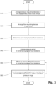
- FIG. 5 shows a flowchart depicting steps of a further embodiment of a method of controlling an HVAC system 1 comprising a fluid transportation network 100 according to the present disclosure.
- a section flow rate ⁇ S a-z is measured in using a section flow sensor SF, SF a-z arranged in the supply line LS, LS a-z and/or the return line LR, LR a-z of the network section F, F a-z .
- the flow regulating device PI 1 , PI 1.a-z in the first zone Z 1 Z maxRes , Z maxRes.a-z of highest fluid resistance amongst the plurality of zones Z 1-n , Z 1-n, a-z is controlled - such as to maintain the section flow rate(s) ⁇ S a-z above a minimum flow rate.
- FIG. 6 shows a highly schematic block diagram of a further embodiment of an HVAC system 1 according to the present disclosure, further comprising a bypass flow regulating device PI Bypass at a location of highest fluid resistance within each network section F.
- the bypass flow regulating device PI Bypass is arranged at a location of highest fluid resistance within the network section F, even higher than the fluid resistance in any one of the flow regulated zone Z 1-n (i.e. zones comprising a flow regulating device PI 1-n ).
- the controller 20 controls the bypass flow regulating device PI Bypass such as to maintain the section flow rate ⁇ S a-z above a minimum flow rate.
- the bypass flow regulating device PI Bypass is opened in order to ensure a minimum section flow rate ⁇ S a-z despite the flow regulating devices PI 1-n of the zones Z 1-n being closed.
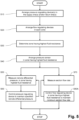
- FIG. 7 shows a flowchart depicting steps of a further embodiment of a method of controlling an HVAC system 1 comprising a fluid transportation network 100 according to the present disclosure.
- the bypass flow regulating device PI Bypass , PI Bypass, a-z is controlled such as to maintain the section flow rate ⁇ S a-z above a minimum flow rate, thereby ensuring that each zone Z 1-n , Z 1-n , a-z operates in the specified differential pressure range and at the same time it ensured that a minimum flow of fluid flows through the network section F, F a-z .
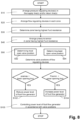
- Figure 8 shows a flowchart depicting steps of a further embodiment of a method of controlling an HVAC system 1 comprising a fluid transportation network 100 according to the present disclosure.
- figure 8 further comprises steps for operating a fluid flow generator P of the fluid transportation circuit(s) C, C a-z efficiently.
- current valve (or damper) positions pos 1-n of the flow regulating device PI 1-n , PI a-z,1-n of each of the zones Z 1-n , Z 1-n, a-z is determined, the current positions pos 1-n being indicative of opening of the respective flow regulating device PI 1-n , PI a-z,1-n .
- a currently most open position pos max amongst the positions pos 1-n of all of the flow regulating devices PI 1-n of each of the zones Z 1-n is determined.
- a currently least open position pos min amongst the current positions pos 1-n of all of the flow regulating devices PI 1-n of each of the zones Z 1-n is determined.
- a power level of fluid flow generator(s) P - such as a pumping power of a pump of the fluid transportation circuit C, C a-z - is controlled in accordance with the current positions pos 1-n .
- the power level of the fluid flow generator(s) P, P a-z is reduced if the currently most open position pos max is below a lower opening limit.
- the power level of the fluid flow generator(s) P is increased if the currently least open position pos min exceeds an upper opening limit.
- FIG. 9 shows a highly schematic block diagram of a further embodiment of an HVAC system 1 according to the present disclosure.
- the fluid transportation network 100 of the embodiment shown in figure 9 comprises a plurality of network sections F a-z each connected to a fluid transportation circuit C a-z through a supply line LS a-z and a return line LR a-z .
- Each network section F a-z comprises a plurality of parallel zones Z a-z.1-n .
- Each of the zones Z a-z.1-n comprises one or more thermal energy exchangers 80 a-z,1-n , e.g. heat exchangers for heating the zone Z a-z.1-n or chillers for cooling the zone Z a-z.1-n .
- pressure regulating devices PR a-z are arranged in the return lines LR a-z of each network section F a-z
- flow regulating devices PI a-z.1-n are arranged in the zones Z a-z.1-n .
- the HVAC system 1 further comprises pressure sensors SP a-z configured and arranged for measurement of the remote differential pressures dp Rem , a-z in the first zones Z maxRes , a-z , the first zones Z maxRes , a-z each having a highest fluid resistance amongst the plurality of zones Z a-z.1-n within the respective network section F a-z . Furthermore, section flow sensors SF a-z are arranged in the return lines LR a-z of each network section F a-z .
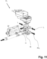
- FIGS 10A and 10B show highly schematic block diagrams of further embodiments of an HVAC system 1 according to the present disclosure, comprising a plurality of fluid transportation circuits C H , Cc within one network section F.
- the flow regulating device(s) PI 1-n comprises a six-way valve(s).
- the first fluid transportation circuit C H is depicted with double lines
- the second fluid transportation circuit Cc is depicted with single lines.
- the zone supply and return lines ZLS n and ZLR n are depticted in single lines as well, but are part of both of the alternative fluid transportation circtuits C H , C C .
- the six-way valve(s) are provided in addition to the flow regulating valves of the flow regulating devices PI 1-n , which are configured and controlled for regulating the flow rate ⁇ 1-n of the fluid.
- the six-way valve(s) are provided as flow regulating devices PI 1-n , the six-way valves being configured to both regulate the flow rate ⁇ 1-n of the fluid and to alternatively couple the zone Z 1-n to the first fluid transportation circuit C H or to the second fluid transportation circuit Cc.
- a pressure sensor SP H is arranged for measurement of the remote differential pressure dp Rem , dp Rem.a-z over the first zone Z maxRes , Z maxRes,a-z when connected to the first fluid transportation circuit C H and a second pressure sensor SPc is arranged for measurement of the remote differential pressure dp Rem , dp Rem.a-z over the first zone Z maxRes , Z maxRes,a-z when connected to the second fluid transportation circuit C C .
- the six-way valves PI 1-n each comprise a first fluid input port I 1 , a second fluid input port I 2 , a fluid output port O, a fluid return input port RI, a first fluid return output port RO 1 and a second fluid return output port RO 2 .
- the first fluid input port I 1 and the first fluid return output port RO 1 are fluidically connected to a supply line LS H respectively a return line LR H of the (first) fluid transportation circuit C H
- the second fluid input port I 2 and the second fluid return output port ROz are fluidically connected to a second supply line LSc respectively a second return line LRc of the second transportation circuit Cc.
- the fluid output port O and the fluid return input port RI are fluidically connected with the heat exchanger 80 1-n .
- fluid transportation network 100 network sections (of fluid transportation network) F, F a-z fluid transportation circuit C, C a-z ,C H , Cc supply line (of fluid transportation circuit) LS, LS a-z return line(of fluid transportation circuit) LR, LR a-z parallel zones (of network section(s)) Z 1-n , Z a-z.1-n zone supply line ZLS 1-n , ZLS a-z.1-n zone return line ZLR 1-n , ZLR a-z.1-n first zone (with highest fluid resistance) Z maxRes , Z maxRes , a-z thermal energy exchanger 80 1-n , 80a-z,1-n flow regulating device PI 1-n , PI a-z.1-n pressure regulating device PR, PR a-z remote differential pressure dp Rem , dp Rem.a-z controller 20 pressure sensor SP, SP a-z , SP H , SPc section flow sensor SF, SF a-z fluid
Landscapes
- Engineering & Computer Science (AREA)
- Mechanical Engineering (AREA)
- General Engineering & Computer Science (AREA)
- Chemical & Material Sciences (AREA)
- Combustion & Propulsion (AREA)
- Physics & Mathematics (AREA)
- Signal Processing (AREA)
- Fluid Mechanics (AREA)
- Mathematical Physics (AREA)
- Thermal Sciences (AREA)
- Fuzzy Systems (AREA)
- Life Sciences & Earth Sciences (AREA)
- Sustainable Development (AREA)
- Human Computer Interaction (AREA)
- Control Of Fluid Pressure (AREA)
- Air Conditioning Control Device (AREA)
- Flow Control (AREA)
- Feedback Control In General (AREA)
Claims (18)
- Verfahren zur Kontrolle eines Heizung, Lüftung und Klimatisierung HLK-Systems (1), das ein Fluidtransportnetzwerk (100) umfasst, das einen oder mehrere Netzwerkabschnitte (F, Fa-z) umfasst, wobei jeder Netzwerkabschnitt (F, Fa-z) über diejeweilige(n) Versorgungsleitung(en) (LS, LSa-z) und Rücklaufleitung(en) (LR, LRa-z) mit einem Fluidtransportkreislauf (C, Ca-z) verbunden ist, wobei jeder Netzwerkabschnitt (F, Fa-z) mehrere parallele Zonen (Z1-n , Za-z.1-n) umfasst, wobei das Verfahren umfasst:- Anordnung einer Druckregulierungsvorrichtung (PR, PRa-z) in der/den Versorgungsleitung(en) (LS, LSa-z) und/oder der/den jeweiligen Rücklaufleitung(en) (LR, LRa-z) des/der Netzwerkabschnitte(s) (F, Fa-z);- Anordnung von Durchflussregelungsvorrichtungen (PI1-n, PIa-z.1-n) in den Zonen (Z1-n , Za-z.1-n) der Netzwerkabschnitte (Fa-z);- Anordnen eines Drucksensors (SP, SPa-z, SPH, SPc) zur Messung eines Ferndifferenzdrucks dpRem , dpRem.a-z in einer ersten Zone (ZmaxRes, ZmaxRes,a-z ), wobei die erste Zone (ZmaxRes, ZmaxRes,a-z ) einen höchsten Fluidwiderstand unter der Vielzahl von Zonen (Z1-n , Za-z.1-n) innerhalb des jeweiligen Netzwerkabschnitts (F, Fa-z) des einen oder der mehreren Netzwerkabschnitte (F, Fa-z) aufweist;- Messung des Ferndifferenzdrucks dpRem, dpRem,a-z des Fluids in der ersten Zone (ZmaxRes, ZmaxRes, a-z), und- Steuern der Druckregulierungsvorrichtung(en) (PR, PRa-z) eines jeden Netzwerkabschnitts (F, Fa-z) zur Kontrolle, um den gemessenen Ferndifferenzdruck dpRem , dpRem, a-z innerhalb eines bestimmten Differenzdruckbereichs zu halten
- Das Verfahren nach Anspruch 1, bei dem eine oder mehrere der Durchflussregelungsvorrichtungen (PI1-n, PIa-z.1-n) druckinvariante Regelungsvorrichtung(en) (PI1-n , PIa-z.1-n) sind, die so konfiguriert sind, dass sie die jeweiligen Zonen (Z1-n , Za-z.1-n) als druckunabhängige Zweige des jeweiligen Netzwerkabschnitts (F, Fa-z) realisieren.
- Das Verfahren nach Anspruch 2, das ferner umfasst:- Bestimmen eines Fluidwiderstandes jeder einer Vielzahl von Zonen (Z1-n, Za.z.1-n) innerhalb des jeweiligen Netzwerkabschnitts (F, Fa-z); und- Bestimmen der ersten Zone (ZmaxRes, ZmaxRes,a-z) mit dem höchsten Fluidwiderstand unter der Mehrzahl von Zonen (Z1-n, Za-z,1-n) innerhalb des jeweiligen Netzwerkabschnitts (F, Fa-z ) basierend auf dem Fluidwiderstand jeder der Vielzahl von Zonen (Z1-n , Za-z,1-n).
- Das Verfahren nach Anspruch 3, wobei das Bestimmen eines Fluidwiderstandes jeder der Vielzahl von Zonen (Z1-n , Za-z.1-n) eines oder mehrere von folgendem umfasst:- Berechnen des Fluidwiderstandes der Zonen (Z1-n , Za-z.1-n) mathematisch basierend auf deren Geometrie;- Einstellen einer oder mehrerer Durchflussregelungsvorrichtungen (PI1-n, PIa-z.1-n), die in einer oder mehreren der Zonen (Z1-n , Za-z.1-n) angeordnet sind, auf ihre jeweilige vollständig geöffnete Einstellung und Messen eines Zonendrucks dp1-n in jeder der Mehrzahl von Zonen (Z1-n , Za-z.1-n), um die erste Zone (ZmaxRes, ZmaxRes,a-z) mit dem höchsten Fluidwiderstand unter der Mehrzahl von Zonen (Z1-n, Za-z.1-n) innerhalb des jeweiligen Netzwerkabschnitts (F, Fa-z) zu bestimmen; und/oder- sukzessives Schließen der Durchflussregelungsvorrichtungen (PI1-n , PIa-z.1-n) in allen ausser einer ausgewählten Zone Zselect der Vielzahl paralleler Zonen (Z1-n, Za-z.1-n) der Netzwerkabschnitte (Fa-z), um einen Fluiddruck in der ausgewählten Zone Zselect zu bestimmen
- Das Verfahren nach einem der Ansprüche 1 bis 4, wobei das Anordnen von Drucksensor(en) (SP, SPa-z, SPH, SPc) zur Messung des Ferndifferenzdrucks dpRem, dpRem.a-z in der ersten Zone (ZmaxRes, ZmaxRes.a-z) das Anordnen des/der Drucksensors/en (SP, SPa-z, SPH, SPC) zum Messen eines Differenzdrucks zwischen einer Versorgungsleitung (ZLS1, ZLSa-z.1) und einer Rücklaufleitung (ZLR1, ZLRa-z.1) der ersten Zone (ZmaxRes, ZmaxRes.a-z) umfasst.
- Das Verfahren nach einem der Ansprüche 1 bis 5, wobei das Anordnen von Drucksensor(en) (SP, SPa-z, SPH , SPc) zur Messung des Ferndifferenzdrucks dpRem , dpRem.a-z in der ersten Zone (ZmaxRes, ZmaxRes.a-z) umfasst, das Anordnen des Drucksensors/der Drucksensoren (SP, SPa-z, SPH, SPC) zum Messen eines Differenzdrucks über der Durchflussregelungsvorrichtung (PI1 , PIa-z.1 ) in der ersten Zone (ZmaxRes, ZmaxRes.a-z).
- Das Verfahren nach einem der Ansprüche 1 bis 6, das ferner umfasst:- Messung der Abschnittsdurchflussrate(n) ΦSa-z unter Verwendung von Abschnittsdurchflusssensoren (SF, SFa-z), die in der/den Versorgungsleitung(en) (LS, LSa-z) oder der jeweiligen Rücklaufleitung(en) (LR, LRa-z) eines oder mehrerer Netzwerkabschnitte (F, Fa-z) angeordnet sind; und- Steuern, durch die Steuereinheit (20) der Durchflussregelungsvorrichtung(en) (PI1, PIa-z,1) in der/den ersten Zone(n) (ZmaxRes, ZmaxRes,a-z) - die mit dem höchsten Fluidwiderstand unter den mehreren Zonen (Z1-n , Za-z.1-n) - so dass die Abschnittsdurchflussrate(n) ΦSa-z über einer Mindestdurchflussrate gehalten wird
- Das Verfahren nach einem der Ansprüche 1 bis 7, das ferner umfasst:- Messen einer Abschnittsdurchflussrate ΦSa-z in den Versorgungsleitungen (LS, LSa-z) oder jeweiligen Rücklaufleitungen (LR, LRa-z) jedes der Netzwerkabschnitte (F, Fa-z) unter Verwendung von Abschnittsdurchflusssensor(en) (SF, SFa-z), die in der Versorgungsleitung (LS, LSa-z) und/oder der/den Rücklaufleitung(en) (LR, LRa-z) jedes der Netzwerkabschnitte (F, Fa-z) angeordnet sind;- Anordnen einer Umleit-Durchflussregelungsvorrichtung (PIBypass) an einer Stelle mit dem höchsten Fluidwiderstand innerhalb des jeweiligen Netzwerkabschnitts (F, Fa-z); und- Steuern, durch die Steuereinheit (20) der Umleit-Durchflussregelungsvorrichtung (PIBypass), so dass die Abschnittsdurchflussrate ΦSa-z oberhalb einer Mindestdurchflussrate gehalten wird
- Das Verfahren nach Anspruch 7 oder 8, das ferner umfasst:- Messen einer Fluidtemperatur an der/den jeweiligen Versorgungsleitung(en) (LS, LSa-z) und/oder Rücklaufleitung(en) (LR, LRa-z) eines jeden Netzwerkabschnitts (F, Fa-z); und- Einstellen der Mindestdurchflussrate in Übereinstimmung mit der gemessenen Fluidtemperatur
- Das Verfahren nach einem der Ansprüche 5 bis 9, ferner umfassend, den bestimmten Differenzdruckbereich durch einen Druckausgleichswert zu kompensieren, falls eine aktuelle Position posi der Durchflussregelungsvorrichtung (PI1, PIa-z.1) in der ersten Zone (ZmaxRes, ZmaxRes,a-z) unterhalb eines Mindestöffnungsschwellenwertes liegt.
- Das Verfahren nach Anspruch 10 ferner umfassend das Bestimmen des Druckausgleichswertes basierend auf einem geschätzten Differenzdruck in einer zweiten Zone (Z2, Za-z.2) mit dem zweithöchsten Fluidwiderstand unter den mehreren Zonen (Z1-n, Za-z.1-n) innerhalb des jeweiligen Netzwerkabschnitts (F, Fa-z).
- Das Verfahren nach einem der Ansprüche 1 bis 11, das ferner umfasst:- Bestimmen aktueller Positionen pos1-n der Durchflussregelungsvorrichtung (PI1-n, PIa-z.1-n) jeder der Zonen (Z1-n, Za-z.1-n), wobei die aktuellen Positionen pos1-n eine Indikation für das Öffnen der jeweiligen Durchflussregelungsvorrichtung (PI1-n, PIa-z.1-n) zu einem bestimmten Zeitpunkt sind;- Steuern, durch die Steuereinheit (20) eines Leistungsniveaus des/der Fluiddurchflusserzeuger(s) wie einer Pumpleistung der Pumpe(n) (P, Pa-z) des Fluidtransportkreislaufs (C, Ca-z) in Übereinstimmung mit den aktuellen Positionen pos1-n.
- Das Verfahren nach Anspruch 12, das ferner umfasst:- Bestimmen einer aktuell am meisten geöffneten Position posmax und/oder einer aktuell am wenigsten geöffneten Position posmin unter den Positionen pos1-n der Durchflussregelungsvorrichtungen (PI1-n, PIa-z.1-n) jeder der Zonen (Z1-n, Za-z.1-n);- Verringern des Leistungsniveaus des/der Fluiddurchflusserzeuger(s) (P, Pa-z), wenn die am weitesten geöffnete Position posmax unterhalb einer unteren Öffnungsgrenze liegt und/oder Erhöhen des Leistungsniveaus des/der Fluiddurchflusserzeuger(s) (P, Pa-z), wenn die aktuell am wenigsten geöffnete Position posmin eine obere Öffnungsgrenze überschreitet
- Das Verfahren nach Anspruch 13, das ferner umfasst:- Anordnen von Zonendurchflussratensensoren in jeder der Zonen (Z1-n, Za-z.1-n) der Netzwerkabschnitte (Fa-z);- Messen einer tatsächlichen Durchflussrate Φ1-n, Φa-z.1-n durch die jeweilige Zone (Z1-n, Za-z.1-n) mit Hilfe der Zonendurchflussratensensoren;- Nichtberücksichtigen der in Zone(n) (Z1-n, Za-z.1-n) angeordneten Durchflussregelungsvorrichtung(en) (PI1-n, PIa-z.1-n), bei denen die tatsächliche Durchflussrate Φ1-n ,Φa-z.1-n unterhalb eines Durchflussratenschwellenwerts liegt, bei der Bestimmung der aktuell am weitesten geöffneten Position posmax der Positionen pos1-n.
- Das Verfahren nach einem der Ansprüche 1 bis 14, bei dem eine oder mehrere der Durchflussregelungsvorrichtung(en) (PI1-n, PIa-z.1-n) als Sechs-Wege-Ventil(e) ausgeführt sind, das/die so konfiguriert ist/sind, dass es/sie jede Zone (Z1-n, Za-z.1-n) alternativ an einen ersten Fluidtransportkreislauf (CH) oder an einen zweiten Fluidtransportkreislauf (Cc) koppelt/koppeln.
- Ein Heizung, Lüftung und Klimatisierung HLK (1) System, das Folgendes umfasst:- ein Fluidtransportnetzwerk (100) mit einem oder mehreren Netzwerkabschnitten (F, Fa-z), wobei jeder Netzwerkabschnitt (F, Fa-z) über die jeweilige(n) Versorgungsleitung(en) (LS, La-z) und Rücklaufleitung(en) (LR, LRa-z) mit einem Fluidtransportkreislauf (C, Ca-z) verbunden ist, wobei jeder Netzwerkabschnitt (F, Fa-z) eine Vielzahl von parallelen Zonen (Z1-n , Za-z.1-n) umfasst;- eine Durchflussregelungsvorrichtung (PI1-n, PIa-z.1-n), die in jeder der Zonen (Z1-n, Za-z.1-n) der Netzwerkabschnitte (F, Fa-z) angeordnet ist;- eine Druckregulierungsvorrichtung (PR, PRa-z), die in den Versorgungsleitungen (LS, LSa-z) und/oder den jeweiligen Rücklaufleitungen (LR, LRa-z) jedes der Netzwerkabschnitte (F, Fa-z) angeordnet ist;- einen Drucksensor (SP, SPa-z, SPH, SPc) zur Messung eines Ferndifferenzdrucks dpRem, dpRem.a-z, der in einer ersten Zone (ZmaxRes, ZmaxRes,a-z) angeordnet ist, wobei die erste Zone (ZmaxRes, ZmaxRes,a-z) einen höchsten Fluidwiderstand unter den mehreren Zonen (Z1-n , Za-z.1-n) innerhalb des jeweiligen Netzwerkabschnitts (F, Fa-z) des einen oder der mehreren Netzwerkabschnitte (F, Fa-z) hat, und- eine Steuereinheit (20),wobei die Steuereinheit (20) des HLK-Systems (1) so konfiguriert ist, dass sie die Druckregulierungsvorrichtung(en) (PR, PRa-z) jedes Netzwerkabschnitts (F, Fa-z) so steuert, dass der von dem Drucksensor (SP, SPa-z, SPH, SPc) gemessene Ferndifferenzdruck dpRem, dpRema-z in der ersten Zone (ZmaxRes, ZmaxRes,a-z) innerhalb eines bestimmten Differenzdruckbereichs gehalten wird
- Das HLK-System (1) nach Anspruch 16, das ferner Abschnittsdurchflusssensoren (SF, SFa-z) umfasst, die zum Messen der Abschnittsdurchflussrate(n) ΦSa-z in der/den Versorgungsleitung(en) (LS, LSa-z) oder der jeweiligen Rücklaufleitung(en) (LR, LRa-z) eines oder mehrerer der Netzwerkabschnitte (F, Fa-z) angeordnet sind,
wobei die Steuereinheit (20) ferner zum Steuern der Durchflussregelungsvorrichtung(en) (PI1, PIa-z,1) in der/den ersten Zone(n) (ZmaxRes, ZmaxRes,a-z) - mit dem höchsten Fluidwiderstand unter den mehreren Zonen (Z1-n , Za-z.1-n) - konfiguriert ist, um die Abschnittsdurchflussrate(n) ΦSa-z über einer Mindestdurchflussrate zu halten. - Das HLK-System (1) nach Anspruch 16 oder 17, das ferner umfasst:- Durchflusssensor(en) (SF, SFa-z), der/die zur Messung einer Abschnittsdurchflussrate ΦSa-z in den Versorgungsleitungen (LS, LSa-z) oder jeweiligen Rücklaufleitungen (LR, LRa-z) jedes der Netzwerkabschnitte (F, Fa-z) angeordnet ist/sind; und- eine Umleit-Durchflussregelungsvorrichtung (PIBypass), die an einer Stelle mit dem höchsten Fluidwiderstand innerhalb des jeweiligen Netzwerkabschnitts (F, Fa-z) angeordnet ist,wobei die Steuereinheit (20) ferner konfiguriert ist, um die Umleit-Durchflussregelungsvorrichtung (PIBypass) so zu steuern, dass die Abschnittsdurchflussrate ΦSa-z über einer Mindestdurchflussrate gehalten wird.
Applications Claiming Priority (1)
| Application Number | Priority Date | Filing Date | Title |
|---|---|---|---|
| CH9342022 | 2022-08-08 |
Publications (3)
| Publication Number | Publication Date |
|---|---|
| EP4095449A2 EP4095449A2 (de) | 2022-11-30 |
| EP4095449A3 EP4095449A3 (de) | 2023-05-31 |
| EP4095449B1 true EP4095449B1 (de) | 2024-07-31 |
Family
ID=82850545
Family Applications (1)
| Application Number | Title | Priority Date | Filing Date |
|---|---|---|---|
| EP22200387.3A Active EP4095449B1 (de) | 2022-08-08 | 2022-10-07 | Ein verfahren, system und computerprogrammprodukt zur steuerung einer hlk-anlage |
Country Status (3)
| Country | Link |
|---|---|
| US (1) | US20240044543A1 (de) |
| EP (1) | EP4095449B1 (de) |
| CN (1) | CN117537461A (de) |
Families Citing this family (1)
| Publication number | Priority date | Publication date | Assignee | Title |
|---|---|---|---|---|
| WO2025202083A1 (en) * | 2024-03-28 | 2025-10-02 | Belimo Holding Ag | A hvac field device, hvac system, method of operating an hvac field device and a computer program product for regulating a differential pressure of a network section of a fluid transportation network |
Family Cites Families (2)
| Publication number | Priority date | Publication date | Assignee | Title |
|---|---|---|---|---|
| DE102010022763A1 (de) * | 2010-06-05 | 2011-12-08 | Oventrop Gmbh & Co. Kg | Verfahren zum automatischen hydraulischen Abgleich in fluidführenden Anlagen |
| CN104089328B (zh) * | 2013-04-01 | 2018-10-12 | 开利公司 | 空调系统以及对空调系统进行控制的方法 |
-
2022
- 2022-10-07 EP EP22200387.3A patent/EP4095449B1/de active Active
-
2023
- 2023-06-16 US US18/336,291 patent/US20240044543A1/en active Pending
- 2023-08-03 CN CN202310970449.XA patent/CN117537461A/zh active Pending
Also Published As
| Publication number | Publication date |
|---|---|
| EP4095449A2 (de) | 2022-11-30 |
| US20240044543A1 (en) | 2024-02-08 |
| EP4095449A3 (de) | 2023-05-31 |
| CN117537461A (zh) | 2024-02-09 |
Similar Documents
| Publication | Publication Date | Title |
|---|---|---|
| TWI760351B (zh) | 用於建築物以運作與改造hvac配置的方法及主控制器 | |
| Taylor | Increasing efficiency with VAV system static pressure setpoint reset | |
| DK1754004T3 (en) | Cooling and / or heating device | |
| US20120193066A1 (en) | Fan coil air conditioning system, a fan coil unit, and a method of controlling a fan coil air conditioning syst | |
| JP5869394B2 (ja) | 熱媒体配管システム | |
| EP4095449B1 (de) | Ein verfahren, system und computerprogrammprodukt zur steuerung einer hlk-anlage | |
| EP3475623A1 (de) | Verfahren und vorrichtung zur kontrolle eines flüssigkeitstransportnetzes | |
| WO2018095609A2 (en) | Hydronic system and method for operating such hydronic system | |
| EP3525060B1 (de) | Flusssteuerungsmodul und verfahren zur steuerung des flusses in einem hydronischen system | |
| EP3407153B1 (de) | Steuerung eines druckreglers an grenzwerten | |
| EP4413303B1 (de) | Flüssigkeitstransportnetz und verfahren | |
| WO2018011621A1 (en) | Method for improving operational efficiency of a cooling system through retrofitting a building with a master controller | |
| DK181986B1 (en) | Method to control a heating system | |
| EP4327031B1 (de) | Hlk sensor gerät | |
| CN112049806A (zh) | 输送装置,方法以及系统 | |
| Bhatia | HVAC chilled water distribution schemes | |
| JP4884707B2 (ja) | 流体搬送システムの制御装置 | |
| WO2011132198A2 (en) | Heating, ventilation, air-conditioning system and method to operate such system | |
| Rasmussen et al. | Heating, ventilating, and air-conditioning control systems | |
| Taylor | Changeover Controls & Coils. | |
| Zheng et al. | Supply air temperature control using a VFD Pump | |
| Rose | Reducing the pressure of the climate change levy | |
| Turner et al. | The Chilled Water and Hot Water Building Differential Pressure Setpoint Calculation-Chilled Water and Hot Water Pump Speed Control |
Legal Events
| Date | Code | Title | Description |
|---|---|---|---|
| PUAI | Public reference made under article 153(3) epc to a published international application that has entered the european phase |
Free format text: ORIGINAL CODE: 0009012 |
|
| STAA | Information on the status of an ep patent application or granted ep patent |
Free format text: STATUS: THE APPLICATION HAS BEEN PUBLISHED |
|
| AK | Designated contracting states |
Kind code of ref document: A2 Designated state(s): AL AT BE BG CH CY CZ DE DK EE ES FI FR GB GR HR HU IE IS IT LI LT LU LV MC ME MK MT NL NO PL PT RO RS SE SI SK SM TR |
|
| REG | Reference to a national code |
Ref country code: DE Ref legal event code: R079 Free format text: PREVIOUS MAIN CLASS: F24F0003060000 Ipc: F24F0140120000 Ref country code: DE Ref legal event code: R079 Ref document number: 602022004959 Country of ref document: DE Free format text: PREVIOUS MAIN CLASS: F24F0003060000 Ipc: F24F0140120000 |
|
| PUAL | Search report despatched |
Free format text: ORIGINAL CODE: 0009013 |
|
| AK | Designated contracting states |
Kind code of ref document: A3 Designated state(s): AL AT BE BG CH CY CZ DE DK EE ES FI FR GB GR HR HU IE IS IT LI LT LU LV MC ME MK MT NL NO PL PT RO RS SE SI SK SM TR |
|
| RIC1 | Information provided on ipc code assigned before grant |
Ipc: F24D 19/10 20060101ALI20230424BHEP Ipc: F24F 11/89 20180101ALI20230424BHEP Ipc: F24F 11/64 20180101ALI20230424BHEP Ipc: F24F 11/49 20180101ALI20230424BHEP Ipc: F24F 5/00 20060101ALI20230424BHEP Ipc: F24F 3/06 20060101ALI20230424BHEP Ipc: F24F 11/85 20180101ALI20230424BHEP Ipc: F24F 11/84 20180101ALI20230424BHEP Ipc: F24F 11/83 20180101ALI20230424BHEP Ipc: F24F 140/12 20180101AFI20230424BHEP |
|
| STAA | Information on the status of an ep patent application or granted ep patent |
Free format text: STATUS: REQUEST FOR EXAMINATION WAS MADE |
|
| 17P | Request for examination filed |
Effective date: 20230911 |
|
| RBV | Designated contracting states (corrected) |
Designated state(s): AL AT BE BG CH CY CZ DE DK EE ES FI FR GB GR HR HU IE IS IT LI LT LU LV MC ME MK MT NL NO PL PT RO RS SE SI SK SM TR |
|
| GRAP | Despatch of communication of intention to grant a patent |
Free format text: ORIGINAL CODE: EPIDOSNIGR1 |
|
| STAA | Information on the status of an ep patent application or granted ep patent |
Free format text: STATUS: GRANT OF PATENT IS INTENDED |
|
| RIC1 | Information provided on ipc code assigned before grant |
Ipc: F24D 19/10 20060101ALI20240409BHEP Ipc: F24F 11/89 20180101ALI20240409BHEP Ipc: F24F 11/64 20180101ALI20240409BHEP Ipc: F24F 11/49 20180101ALI20240409BHEP Ipc: F24F 5/00 20060101ALI20240409BHEP Ipc: F24F 3/06 20060101ALI20240409BHEP Ipc: F24F 11/85 20180101ALI20240409BHEP Ipc: F24F 11/84 20180101ALI20240409BHEP Ipc: F24F 11/83 20180101ALI20240409BHEP Ipc: F24F 140/12 20180101AFI20240409BHEP |
|
| GRAJ | Information related to disapproval of communication of intention to grant by the applicant or resumption of examination proceedings by the epo deleted |
Free format text: ORIGINAL CODE: EPIDOSDIGR1 |
|
| STAA | Information on the status of an ep patent application or granted ep patent |
Free format text: STATUS: REQUEST FOR EXAMINATION WAS MADE |
|
| INTG | Intention to grant announced |
Effective date: 20240424 |
|
| GRAP | Despatch of communication of intention to grant a patent |
Free format text: ORIGINAL CODE: EPIDOSNIGR1 |
|
| STAA | Information on the status of an ep patent application or granted ep patent |
Free format text: STATUS: GRANT OF PATENT IS INTENDED |
|
| GRAS | Grant fee paid |
Free format text: ORIGINAL CODE: EPIDOSNIGR3 |
|
| INTC | Intention to grant announced (deleted) | ||
| GRAA | (expected) grant |
Free format text: ORIGINAL CODE: 0009210 |
|
| STAA | Information on the status of an ep patent application or granted ep patent |
Free format text: STATUS: THE PATENT HAS BEEN GRANTED |
|
| INTG | Intention to grant announced |
Effective date: 20240619 |
|
| AK | Designated contracting states |
Kind code of ref document: B1 Designated state(s): AL AT BE BG CH CY CZ DE DK EE ES FI FR GB GR HR HU IE IS IT LI LT LU LV MC ME MK MT NL NO PL PT RO RS SE SI SK SM TR |
|
| REG | Reference to a national code |
Ref country code: CH Ref legal event code: EP Ref country code: GB Ref legal event code: FG4D |
|
| REG | Reference to a national code |
Ref country code: DE Ref legal event code: R096 Ref document number: 602022004959 Country of ref document: DE |
|
| P01 | Opt-out of the competence of the unified patent court (upc) registered |
Free format text: CASE NUMBER: APP_40966/2024 Effective date: 20240710 |
|
| REG | Reference to a national code |
Ref country code: IE Ref legal event code: FG4D |
|
| REG | Reference to a national code |
Ref country code: LT Ref legal event code: MG9D |
|
| REG | Reference to a national code |
Ref country code: NL Ref legal event code: MP Effective date: 20240731 |
|
| PG25 | Lapsed in a contracting state [announced via postgrant information from national office to epo] |
Ref country code: PT Free format text: LAPSE BECAUSE OF FAILURE TO SUBMIT A TRANSLATION OF THE DESCRIPTION OR TO PAY THE FEE WITHIN THE PRESCRIBED TIME-LIMIT Effective date: 20241202 |
|
| REG | Reference to a national code |
Ref country code: AT Ref legal event code: MK05 Ref document number: 1708789 Country of ref document: AT Kind code of ref document: T Effective date: 20240731 |
|
| PG25 | Lapsed in a contracting state [announced via postgrant information from national office to epo] |
Ref country code: PT Free format text: LAPSE BECAUSE OF FAILURE TO SUBMIT A TRANSLATION OF THE DESCRIPTION OR TO PAY THE FEE WITHIN THE PRESCRIBED TIME-LIMIT Effective date: 20241202 |
|
| PG25 | Lapsed in a contracting state [announced via postgrant information from national office to epo] |
Ref country code: NO Free format text: LAPSE BECAUSE OF FAILURE TO SUBMIT A TRANSLATION OF THE DESCRIPTION OR TO PAY THE FEE WITHIN THE PRESCRIBED TIME-LIMIT Effective date: 20241031 |
|
| PG25 | Lapsed in a contracting state [announced via postgrant information from national office to epo] |
Ref country code: GR Free format text: LAPSE BECAUSE OF FAILURE TO SUBMIT A TRANSLATION OF THE DESCRIPTION OR TO PAY THE FEE WITHIN THE PRESCRIBED TIME-LIMIT Effective date: 20241101 Ref country code: NL Free format text: LAPSE BECAUSE OF FAILURE TO SUBMIT A TRANSLATION OF THE DESCRIPTION OR TO PAY THE FEE WITHIN THE PRESCRIBED TIME-LIMIT Effective date: 20240731 Ref country code: FI Free format text: LAPSE BECAUSE OF FAILURE TO SUBMIT A TRANSLATION OF THE DESCRIPTION OR TO PAY THE FEE WITHIN THE PRESCRIBED TIME-LIMIT Effective date: 20240731 Ref country code: PL Free format text: LAPSE BECAUSE OF FAILURE TO SUBMIT A TRANSLATION OF THE DESCRIPTION OR TO PAY THE FEE WITHIN THE PRESCRIBED TIME-LIMIT Effective date: 20240731 |
|
| PG25 | Lapsed in a contracting state [announced via postgrant information from national office to epo] |
Ref country code: BG Free format text: LAPSE BECAUSE OF FAILURE TO SUBMIT A TRANSLATION OF THE DESCRIPTION OR TO PAY THE FEE WITHIN THE PRESCRIBED TIME-LIMIT Effective date: 20240731 |
|
| PG25 | Lapsed in a contracting state [announced via postgrant information from national office to epo] |
Ref country code: LV Free format text: LAPSE BECAUSE OF FAILURE TO SUBMIT A TRANSLATION OF THE DESCRIPTION OR TO PAY THE FEE WITHIN THE PRESCRIBED TIME-LIMIT Effective date: 20240731 |
|
| PG25 | Lapsed in a contracting state [announced via postgrant information from national office to epo] |
Ref country code: IS Free format text: LAPSE BECAUSE OF FAILURE TO SUBMIT A TRANSLATION OF THE DESCRIPTION OR TO PAY THE FEE WITHIN THE PRESCRIBED TIME-LIMIT Effective date: 20241130 Ref country code: AT Free format text: LAPSE BECAUSE OF FAILURE TO SUBMIT A TRANSLATION OF THE DESCRIPTION OR TO PAY THE FEE WITHIN THE PRESCRIBED TIME-LIMIT Effective date: 20240731 |
|
| PG25 | Lapsed in a contracting state [announced via postgrant information from national office to epo] |
Ref country code: HR Free format text: LAPSE BECAUSE OF FAILURE TO SUBMIT A TRANSLATION OF THE DESCRIPTION OR TO PAY THE FEE WITHIN THE PRESCRIBED TIME-LIMIT Effective date: 20240731 |
|
| PG25 | Lapsed in a contracting state [announced via postgrant information from national office to epo] |
Ref country code: ES Free format text: LAPSE BECAUSE OF FAILURE TO SUBMIT A TRANSLATION OF THE DESCRIPTION OR TO PAY THE FEE WITHIN THE PRESCRIBED TIME-LIMIT Effective date: 20240731 Ref country code: RS Free format text: LAPSE BECAUSE OF FAILURE TO SUBMIT A TRANSLATION OF THE DESCRIPTION OR TO PAY THE FEE WITHIN THE PRESCRIBED TIME-LIMIT Effective date: 20241031 |
|
| PG25 | Lapsed in a contracting state [announced via postgrant information from national office to epo] |
Ref country code: RS Free format text: LAPSE BECAUSE OF FAILURE TO SUBMIT A TRANSLATION OF THE DESCRIPTION OR TO PAY THE FEE WITHIN THE PRESCRIBED TIME-LIMIT Effective date: 20241031 Ref country code: PL Free format text: LAPSE BECAUSE OF FAILURE TO SUBMIT A TRANSLATION OF THE DESCRIPTION OR TO PAY THE FEE WITHIN THE PRESCRIBED TIME-LIMIT Effective date: 20240731 Ref country code: NO Free format text: LAPSE BECAUSE OF FAILURE TO SUBMIT A TRANSLATION OF THE DESCRIPTION OR TO PAY THE FEE WITHIN THE PRESCRIBED TIME-LIMIT Effective date: 20241031 Ref country code: NL Free format text: LAPSE BECAUSE OF FAILURE TO SUBMIT A TRANSLATION OF THE DESCRIPTION OR TO PAY THE FEE WITHIN THE PRESCRIBED TIME-LIMIT Effective date: 20240731 Ref country code: LV Free format text: LAPSE BECAUSE OF FAILURE TO SUBMIT A TRANSLATION OF THE DESCRIPTION OR TO PAY THE FEE WITHIN THE PRESCRIBED TIME-LIMIT Effective date: 20240731 Ref country code: IS Free format text: LAPSE BECAUSE OF FAILURE TO SUBMIT A TRANSLATION OF THE DESCRIPTION OR TO PAY THE FEE WITHIN THE PRESCRIBED TIME-LIMIT Effective date: 20241130 Ref country code: HR Free format text: LAPSE BECAUSE OF FAILURE TO SUBMIT A TRANSLATION OF THE DESCRIPTION OR TO PAY THE FEE WITHIN THE PRESCRIBED TIME-LIMIT Effective date: 20240731 Ref country code: GR Free format text: LAPSE BECAUSE OF FAILURE TO SUBMIT A TRANSLATION OF THE DESCRIPTION OR TO PAY THE FEE WITHIN THE PRESCRIBED TIME-LIMIT Effective date: 20241101 Ref country code: FI Free format text: LAPSE BECAUSE OF FAILURE TO SUBMIT A TRANSLATION OF THE DESCRIPTION OR TO PAY THE FEE WITHIN THE PRESCRIBED TIME-LIMIT Effective date: 20240731 Ref country code: ES Free format text: LAPSE BECAUSE OF FAILURE TO SUBMIT A TRANSLATION OF THE DESCRIPTION OR TO PAY THE FEE WITHIN THE PRESCRIBED TIME-LIMIT Effective date: 20240731 Ref country code: BG Free format text: LAPSE BECAUSE OF FAILURE TO SUBMIT A TRANSLATION OF THE DESCRIPTION OR TO PAY THE FEE WITHIN THE PRESCRIBED TIME-LIMIT Effective date: 20240731 Ref country code: AT Free format text: LAPSE BECAUSE OF FAILURE TO SUBMIT A TRANSLATION OF THE DESCRIPTION OR TO PAY THE FEE WITHIN THE PRESCRIBED TIME-LIMIT Effective date: 20240731 |
|
| PG25 | Lapsed in a contracting state [announced via postgrant information from national office to epo] |
Ref country code: RO Free format text: LAPSE BECAUSE OF FAILURE TO SUBMIT A TRANSLATION OF THE DESCRIPTION OR TO PAY THE FEE WITHIN THE PRESCRIBED TIME-LIMIT Effective date: 20240731 Ref country code: DK Free format text: LAPSE BECAUSE OF FAILURE TO SUBMIT A TRANSLATION OF THE DESCRIPTION OR TO PAY THE FEE WITHIN THE PRESCRIBED TIME-LIMIT Effective date: 20240731 Ref country code: SM Free format text: LAPSE BECAUSE OF FAILURE TO SUBMIT A TRANSLATION OF THE DESCRIPTION OR TO PAY THE FEE WITHIN THE PRESCRIBED TIME-LIMIT Effective date: 20240731 |
|
| PG25 | Lapsed in a contracting state [announced via postgrant information from national office to epo] |
Ref country code: EE Free format text: LAPSE BECAUSE OF FAILURE TO SUBMIT A TRANSLATION OF THE DESCRIPTION OR TO PAY THE FEE WITHIN THE PRESCRIBED TIME-LIMIT Effective date: 20240731 |
|
| PG25 | Lapsed in a contracting state [announced via postgrant information from national office to epo] |
Ref country code: CZ Free format text: LAPSE BECAUSE OF FAILURE TO SUBMIT A TRANSLATION OF THE DESCRIPTION OR TO PAY THE FEE WITHIN THE PRESCRIBED TIME-LIMIT Effective date: 20240731 |
|
| PG25 | Lapsed in a contracting state [announced via postgrant information from national office to epo] |
Ref country code: SK Free format text: LAPSE BECAUSE OF FAILURE TO SUBMIT A TRANSLATION OF THE DESCRIPTION OR TO PAY THE FEE WITHIN THE PRESCRIBED TIME-LIMIT Effective date: 20240731 Ref country code: IT Free format text: LAPSE BECAUSE OF FAILURE TO SUBMIT A TRANSLATION OF THE DESCRIPTION OR TO PAY THE FEE WITHIN THE PRESCRIBED TIME-LIMIT Effective date: 20240731 |
|
| REG | Reference to a national code |
Ref country code: DE Ref legal event code: R097 Ref document number: 602022004959 Country of ref document: DE |
|
| PLBE | No opposition filed within time limit |
Free format text: ORIGINAL CODE: 0009261 |
|
| STAA | Information on the status of an ep patent application or granted ep patent |
Free format text: STATUS: NO OPPOSITION FILED WITHIN TIME LIMIT |
|
| PG25 | Lapsed in a contracting state [announced via postgrant information from national office to epo] |
Ref country code: MC Free format text: LAPSE BECAUSE OF FAILURE TO SUBMIT A TRANSLATION OF THE DESCRIPTION OR TO PAY THE FEE WITHIN THE PRESCRIBED TIME-LIMIT Effective date: 20240731 |
|
| 26N | No opposition filed |
Effective date: 20250501 |
|
| PG25 | Lapsed in a contracting state [announced via postgrant information from national office to epo] |
Ref country code: BE Free format text: LAPSE BECAUSE OF NON-PAYMENT OF DUE FEES Effective date: 20241031 Ref country code: LU Free format text: LAPSE BECAUSE OF NON-PAYMENT OF DUE FEES Effective date: 20241007 |
|
| PG25 | Lapsed in a contracting state [announced via postgrant information from national office to epo] |
Ref country code: FR Free format text: LAPSE BECAUSE OF NON-PAYMENT OF DUE FEES Effective date: 20241031 |
|
| REG | Reference to a national code |
Ref country code: BE Ref legal event code: MM Effective date: 20241031 |
|
| PG25 | Lapsed in a contracting state [announced via postgrant information from national office to epo] |
Ref country code: SE Free format text: LAPSE BECAUSE OF FAILURE TO SUBMIT A TRANSLATION OF THE DESCRIPTION OR TO PAY THE FEE WITHIN THE PRESCRIBED TIME-LIMIT Effective date: 20240731 |
|
| PG25 | Lapsed in a contracting state [announced via postgrant information from national office to epo] |
Ref country code: IE Free format text: LAPSE BECAUSE OF NON-PAYMENT OF DUE FEES Effective date: 20241007 |
|
| PGFP | Annual fee paid to national office [announced via postgrant information from national office to epo] |
Ref country code: DE Payment date: 20251020 Year of fee payment: 4 |
|
| PG25 | Lapsed in a contracting state [announced via postgrant information from national office to epo] |
Ref country code: CY Free format text: LAPSE BECAUSE OF FAILURE TO SUBMIT A TRANSLATION OF THE DESCRIPTION OR TO PAY THE FEE WITHIN THE PRESCRIBED TIME-LIMIT; INVALID AB INITIO Effective date: 20221007 |
|
| PG25 | Lapsed in a contracting state [announced via postgrant information from national office to epo] |
Ref country code: HU Free format text: LAPSE BECAUSE OF FAILURE TO SUBMIT A TRANSLATION OF THE DESCRIPTION OR TO PAY THE FEE WITHIN THE PRESCRIBED TIME-LIMIT; INVALID AB INITIO Effective date: 20221007 |